

Fuji Electric ZPA, ZPB, ZPG Instruction Manual

Instruction Manual
INFRARED GAS
ANALYZER
COMMUNICATION
FUNCTIONS (MODBUS)
TYPE: ZPA, ZPB, ZPG
INZ-TN5A1190-E

CONTENTS
1. COMMUNICATION FUNCTIONS ............................................................................................1
1.1 General................................................................................................................................................1
2. SPECIFICATIONS .......................................................................................................................2
2.1 Communication specifications............................................................................................................2
3. CONNECTION.............................................................................................................................3
3.1 Terminal allocation .............................................................................................................................3
3.2 Wiring .................................................................................................................................................4
4. SETTING OF COMMUNICATION CONDITION .....................................................................6
4.1 Set items..............................................................................................................................................6
4.2 Setting operation .................................................................................................................................6
5. MODBUS COMMUNICATION PROTOCOL............................................................................7
5.1 General................................................................................................................................................7
5.2 Composition of message .....................................................................................................................8
5.3 Response of slave station ..................................................................................................................10
5.4 Function code.................................................................................................................................... 11
5.5 Calculation of error check code (CRC-16) .......................................................................................12
5.6 Transmission control procedure........................................................................................................14
6. DETAILS OF MESSAGE ..........................................................................................................16
6.1 Read-out of word data [Function code:03H] ..................................................................................16
6.2 Read-out of read only word data [Function code:04H] .....................................................................18
6.3 Write-in of word data (1 word) [Function code:06H]........................................................................20
6.4 Write-in of continuous word data [Function code:10H] .................................................................21
7. ADDRESS MAP AND DATA FORMAT .................................................................................23
7.1 Data format .......................................................................................................................................23
7.2 Address map .....................................................................................................................................25
7.3 Supplement to address map ..............................................................................................................38
8. TROUBLESHOOTING..............................................................................................................39
INZ-TN5A1190-E i
1. COMMUNICATION FUNCTIONS
1.1 General
• This instrument provides a communication function through RS-485 interface, which allows data transmit to
or receive from the host computer and other devices.
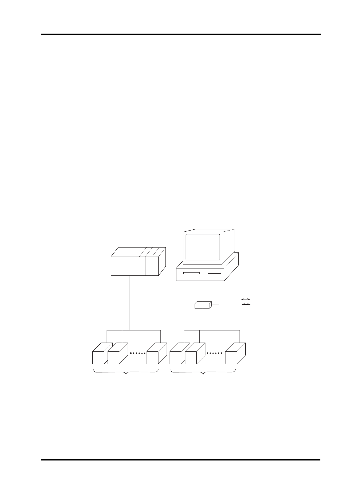
• The communication system is comprised of a master station and slave stations. Up to 31 of slave station
(present instrument) can be connected per master station (host computer, programmable controller, graphic
display panel, etc.) through RS-485 interface.
• Because the master station can communicate with only one slave station at a time, the destination can be
identified by the "Station No" set for each slave station.
• In order that the master station and the slave station can communicate, the format of the transmit/receive data
must coincide. In this instrument, the format of the communication data is determined by the MODBUS
protocol.
[RS-232 RS-485 converter] (recommended article)
Type: KS-485 (non-isolated type)/SYSTEM SACOM Corp.
Type: SI-30FA (isolated type)/SEKISUI ELECTRONICS Co., Ltd.
[USB RS-485 converter] (recommended article)
Type: USB-485I/SYSTEM SACOM Corp.
Programable controller
RS-232C or USB
RS-485
USB RS-485
RS-232C RS-485
Converter
RS-485
Analyzer Analyzer
Fig. 1 Example of connection with host system
INZ-TN5A1190-E 1

2. SPECIFICATIONS
2.1 Communication specifications
RS-485 interface
Item Specification
Electrical specification Based on EIA RS-485
Transmission system 2-wire, semi-duplicate
Synchronizing system Start-stop synchronous system
Connection format 1 : N
Maximum connectable units 31 units
Transmission distance 500m max. (total extension distance)
Transmission speed 38400bps
Data format
Transmission code HEX value (MODBUS RTU mode)
Error detection CRC-16
Isolation Isolation from internal circuit
Data length 8 bits
Stop bit 1 bit
Parity None
X flow control None
Functional isolation between signal line and ground
2 INZ-TN5A1190-E
3. CONNECTION
WARNING
Do not turn on the power supply until all wiring have been completed to avoid electric shock
and malfunctions.
3.1 Terminal allocation
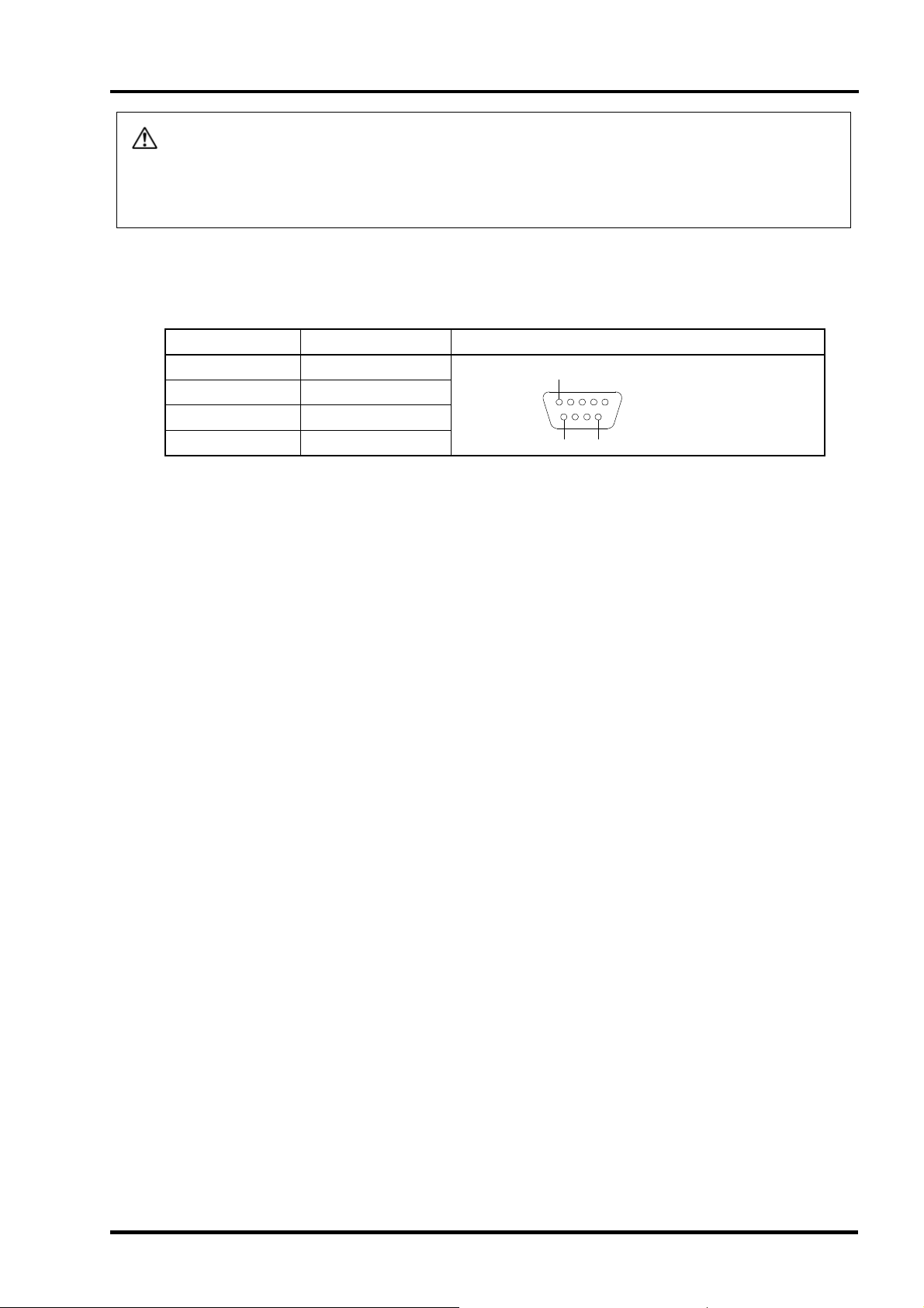
RS-485 interface (RS-485 connector at the rear panel)
Pin No. Signal name Pin connection
1 Signal ground
2 RTxD+
3
Others NC
RTx D−
5
1
9-pin D-Sub
9
6
(female)
INZ-TN5A1190-E 3
3.2 Wiring
RS-485 interface
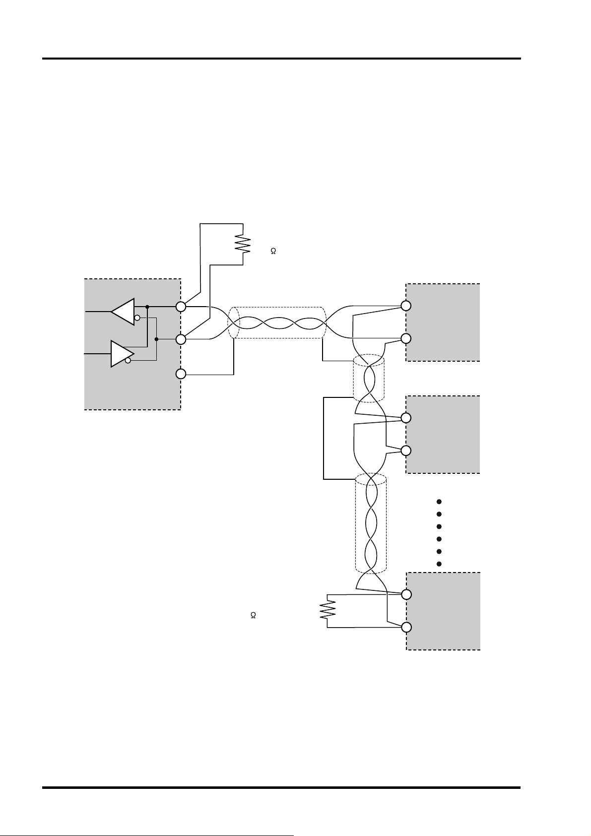
• Please use a shielded twist pair cable. (Recommended cable: KPEV-SB (made by The Furukawa Electric Co., Ltd.))
• The maximum cable length should be 500m. One master and up to thirty-one micro controllers (slaves) can be
connected per circuit.
• Terminate both ends of the circuit with a terminating resistance of 100Ω (1/2W or more).
• Ground the shielded cable once towards the master side.
Terminating resistance
100 (1/2W)
Master
RS-485 interface
or
RS-485 side of
RS-232C to RS-485 conver ter
(USB)
+
–
SG
Shielded twist pair cable
RT x D
RT x D
Slave
+
–
Analyzer
+
–
Analyzer
+
Terminating resistance
100 (1/2W)
• SG does not have to be connected, but it can be used as an effective countermeasure against communication errors
due to noise.
4 INZ-TN5A1190-E
–
Analyzer
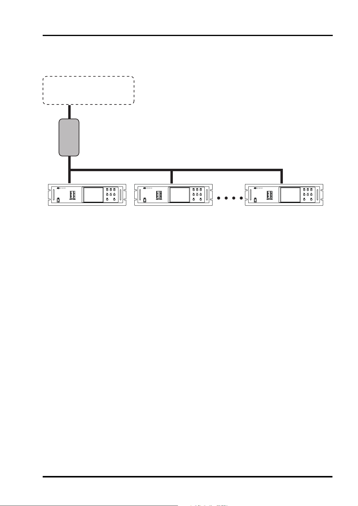
• When using the micro controller in an area where the imposed noise level is expected to exceed 500V, we recommend
using a noise filter on the master side as seen in the figure below.
[Noise filter] (recommended): RSHN-2003 (made by TDK Corporation)
Programmable controller
or
Personal computer
+ RS-232C to RS-485 converter
Noise filter
RS-485
Analyzer
• If there are problems with EMC during communication, the noise level can be reduced by using a communication
cable with a ferrite core.
Ferrite core (recommended): ZCAT series (made by TDK Corporation)
MSFC series (made by Morimiya Electric Co., Ltd.)
INZ-TN5A1190-E 5

4. SETTING OF COMMUNICATION CONDITION
In order that the master station and instrument can correctly communicate, following settings are required.
• All communication condition settings of the master station are the same as those of instruments.
• All instruments connected on a line are set to "Station Nos. (STno)" which are different from each other. (Any
"Station No." is not shared by more than one instrument.)
4.1 Set items
The parameters to be set are shown in the following table. Set them by operating the front panel keys.
Item
Transmission speed 38400bps Fixed (can not be changed)
Data length 8 bits Fixed (can not be changed)
Stop bit 1 bit Fixed (can not be changed)
Parity setting None Fixed (can not be changed)
Station No. 1
Value at
delivery
Setting range Remarks
0 to 31
(0:communication function stop)
Set the same
communication
condition to the master
station and all slave
stations.
Set a different value to
each station.
4.2 Setting operation
Set the station No. on the analyzer maintenance mode display (see the instruction manual).
6 INZ-TN5A1190-E

5. MODBUS COMMUNICATION PROTOCOL
5.1 General
The communication system by the MODBUS protocol is that the communication is always started from the
master station and a slave station responds to the received message.
Transmission procedures is as shown below.
1) The master station sends a command message to a slave station.
2) The slave station checks that the station No. in the received message matches with the own station No.
or not.
3) If matched, the slave station executes the command and sends back the response message.
4) If mismatched, the slave station leaves the command message and wait for the next command message.
a) In case when the station No. in the received command message matches with the own slave station
No.
Master to slave
Slave to master
Command message
Response message
Data on
the line
b) In case when the station No. in the received command message mismatches with the own slave
station No.
Master to slave
Slave to master
Command message
(Not respond)
Data on
the line
The master station can individually communicate with any one of slave stations connected on the same line
upon setting the station No. in the command message.
INZ-TN5A1190-E 7

5.2 Composition of message
Command message and response message consist of 4 fields ; Station No., Function code, Data and Error
check code. And these are send in this order.
Function code (1 byte)
Error check code (CRC-16) (2 bytes)
Fig. 5-1 Composition of message
In the following, each field is explained.
(1) Station No.
Station No. (1 byte)
Data (2 to 133 bytes)
Station No. is the number specifying a slave station. Only a slave station that corresponds to a value to
which "Station No." is set on the analyzer maintenance mode display executes a command.
(2) Function code
This is a code to designate the function executed at a slave station.
For details, refer to section 5.4.
(3) Data
Data are the data required for executing function codes. The composition of data varies with function
codes. For details, refer to chapter 6.
A register number is assigned to each data in the analyzer. For reading/writing the data by
communication, designate the register number.
Note that the register number transmitted on message is expressed as its relative address.
The relative address is calculated by the following expression.
Relative address
The lower 4 digits of the
=
Register number
– 1
For example, when the resister number designated by a function code is 40003,
Relative address = (lower 4 digits of 40003) – 1
= 0002
is used on the message.
8 INZ-TN5A1190-E

(4) Error check code
This is the code to detect message errors (change in bit) in the signal transmission.
On the MODUBUS protocol (RTU mode), CRC-16 (Cycric Redundancy Check) is applied.
For CRC calculation method, refer to section 5.5.
INZ-TN5A1190-E 9

5.3 Response of slave station
(1) Response for normal command
To a relevant message, the slave station creates and sends back a response message which corresponds
to the command message. The composition of message in this case is the same as in section 5.2.
Contents of the data field depend on the function code. For details, refer to Chapter 6.
(2) Response for abnormal command
If contents of a command message have an abnormality (for example, non-actual function code is
designated) other than transmission error, the slave station does not execute that command but creates
and sends back a response message at error detection.
The composition of response message at error detection is as shown in Fig. 5-2 The value used for
function code field is function code of command message plus 80
Table 5-1 gives error codes.
Function code + 80H
Error check(CRC-16)
Station No.
Error code
.
H
Fig. 5-2 Response message at error detection
Tabl e 5-1 Error code
Error code Contents Description
01H Illegal function Non-actual function code is designated.
Check for the function code.
02H Illegal data address
03H Illegal data value
A relative address of a resister number to which the
designated function code can not be used.
Because the designation of number is too much, the
area where resister numbers do not exist is
designated.
(3) No response
Under any of the following items, the slave station takes no action of the command message and sends
back no response.
・ A station number transmitted in the command message differs from the station number specified to
the slave station.
・ A error check code is not matched, or a transmission error (parity error, etc.) is detected.
・ The time interval between the composition data of the message becomes longer than the time
corresponding to 24 bits. (Refer to section 5.6 Transmission control procedure)
10 INZ-TN5A1190-E
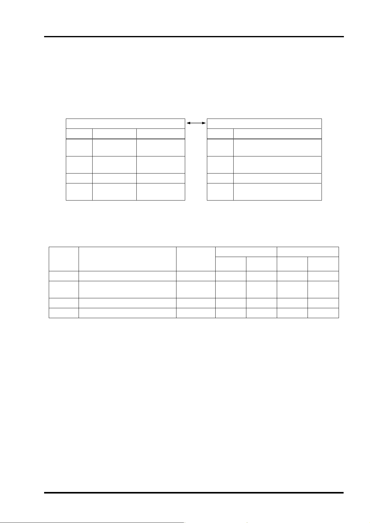
5.4 Function code
According to MODBUS protocol, register numbers are assigned by function codes.
Each function code acts on specific register number.
This correspondence is shown in Table 5-2, and the message length by function is shown in Table 5-3.
Table 5-2 Correspondence between function codes and objective address
Function code Resister No.
No. Function Object No. Contents
03H
04H
06H Write-in Holding register 4xxxx Read-out/write-in word data
10H
Read-out
(continuously)
Read-out
(continuously)
Write-in
(continuously)
Holding register 4xxxx Read-out/write-in word data
Input register 3xxxx Read-out word data
Holding register 4xxxx Read-out/write-in word data
Table 5-3 Function code and message length
Function
code
Contents
Number of
designatable
03H Read-out of word data 64 words
04H
Read-out of word data
64 words
data
Command message Response message
Minimum Maximum Minimum Maximum
8 8 7 133
8 8 7 133
[Unit : byte]
(read-out only)
06H Write-in of word data 1 word 8 8 8 8
10H Write-in of continuous word data 64 words
11 137 8 8
INZ-TN5A1190-E 11
 Loading...