

Page 1
Instruction Manual
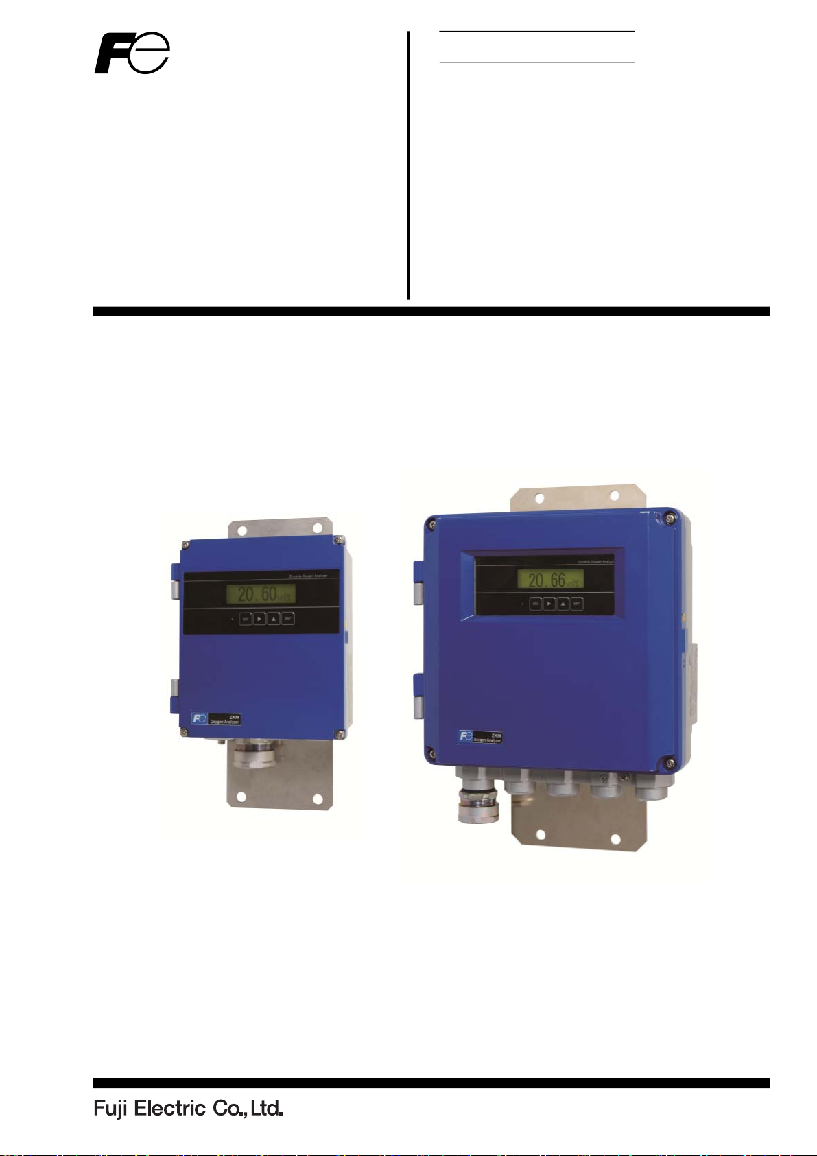
ZIRCONIA OXYGEN
ANALYZER CONVERTER
Type: ZKMA, ZKMB
INZ-TN2ZKMA-E
Page 2

PREFACE
We are grateful for your purchase of Fuji Direct Insertion Type Zirconia Oxygen Analyzer Converter (ZKM).
First read this instruction manual carefully until an adequate understanding is acquired, and
then proceed to installation, operation and maintenance of the converter. Improper handling
may result in accidents or injury.
The specifications of this converter will be changed without prior notice for further product
improvement.
Modification of this converter is strictly prohibited unless a written approval is obtained
from the manufacturer. Fuji will not bear any responsibility for a trouble caused by such a
modification.
This instruction manual shall be stored by the person who actually uses the converter.
After reading through the manual, be sure to keep it near at hand for future reference.
This product falls within category 9 (Monitoring and control instruments including indus-
trial monitoring and control instruments) of Annex 1 of EU RoHS directive (2011/65/EU).
Please do not use it for consumer use.
This instruction manual should be delivered to the end user without fail.
Manufacturer: Fuji Electric Co., Ltd.
Type: Described in the nameplate put on the main body
Date of manufacture: Described in the nameplate put on the main body
Product nationality: Japan
Related instruction manual
Direct insertion type zirconia oxygen analyzer detector (Type: ZFK8) ·········· INZ-TN5ZFK8-E
Issued in October 2015
It is prohibited to transfer part or all of this manual without Fuji
Notice
Electric’s permission in written format.
Description in this manual is subject to change without prior no-
tice.
Fuji Electric Co., Ltd. 2015
INZ-TN2ZKMA-E
- i -
Page 3
SAFETY PRECAUTIONS
First of all, read this “SAFETY PRECAUTIONS” carefully, and then use in the correct way.
Installation, transportation, wiring, use, maintenance of this product shall be carried out by suitably trained
personnel.
First-time users should operate the instrument under the supervision of a fully competent person in the
operation.
Be sure to observe the instructions shown below, because they describe important information on safety.
Those safety precautions are ranked in 3 levels, “DANGER”, “CAUTION” and “PROHIBITION”.
If operation is incorrect, a dangerous situation may occur, resulting in
DANGER
CAUTION
PROHIBITION
death or serious injuries.
If handled wrongly, a dangerous situation may occur, and medium trouble or slight injury may be caused and only property damage may be
caused.
Items which must not be done are noted.
The items noted under “
All the items are important and must be fully observed.
DANGER
CAUTION
CAUTION
Caution on installation and transportation
” may also result in serious trouble depending on circumstances.
This unit is not explosion-proof type. Do not use it in an atmosphere
of explosive gases. Otherwise serious accidents such as explosion or
fire may result.
This unit should be installed in a place which conforms to the condi-
tions noted in the instruction manual. Otherwise, it may cause electric
shocks, fire, failure or malfunction of the unit.
During installation work, care should be taken to keep the unit free
from entry of cable chips or other foreign objects. Otherwise, it may
cause fire, failure or malfunction of the unit.
For installation, observe the rule on it given in the instruction manual
and select a place where the weight of converter can be endured. Installation at an unsuited place may cause turnover or fall and there is a
risk of injury.
Be sure to wear gloves when handling the unit.
Bare hands may invite an injury.
Before transport, fix the door so that it will not open. Otherwise, the
door may be separated and fall to cause an injury.
- ii -
INZ-TN2ZKMA-E
Page 4
Cautions on wiring
Be sure to turn off all the power before performing wiring. Otherwise
CAUTION
DANGER
CAUTION
electric shock may result.
Be sure to perform class D grounding work.
Otherwise, electric shock or failure may result.
Select a proper wiring material that satisfies the ratings of the instru-
ment. Otherwise, electric shock or fire may result.
Connect power source of correct rating. Connection of a power source
of incorrect rating may lead to a risk of fire.
Cautions on use
If unusual smell or sound has been produced, immediately stop the
instrument. Any discharge produced may cause a fire.
Leaving the converter unused for a long time or restarting it after dis-
use requires procedures different from normal operation or suspension
procedures. Be sure to follow the instructions in each instruction manual. Otherwise, intended performance may not be achieved, or accidents or injury may result.
Do not operate the converter for a long time with its door left open.
Otherwise, dust, foreign matter, etc. may stick on internal walls, thereby causing failure.
PROHIBITION
CAUTION
CAUTION
wise, failure, electric shock or injury may result.
Caution on maintenance and inspection
Before maintenance and check, be sure to turn off the main power
supply and wait until the detector is cooled adequately. Otherwise,
you may suffer a burn.
Before removing the detector from the flue for maintenance and
check, make sure the furnace is stopped. Otherwise, you may suffer a
burn.
Before working, take off a wrist watch, finger ring or the like metallic
accessories. And never touch the instrument with a wet hand. Otherwise, you will have electric shocks.
If the fuse is blown, eliminate the cause, and then replace it with the
one of the same capacity and type as before. Otherwise, it may cause
electric shocks or failure.
Others
If the cause of a failure cannot be identified by referring to the instruc-
tion manual, be sure to contact your dealer or Fuji’s technician in
charge of adjustment. Disassembling the instrument carelessly may
result in electric shock or injury.
Do not use a replacement part other than specified by the instrument
maker. Otherwise, adequate performance will not be provided. Besides, an accident or failure may be caused.
Replacement parts such as a maintenance part should be disposed of
as incombustibles.
Do not touch the input/output terminals with metal or finger. Other-
INZ-TN2ZKMA-E
- iii -
Page 5

WARRANTY AND MAINTENANCE
1. Scope of application
To use this equipment, the following conditions must be met:
the use of the equipment incurs no risk of a serious accident even if a failure or malfunction occurs on the
equipment, and
in case of product failure or malfunction, safety measures such as redundant design, prevention of mal-
function, fail safe system, foolproof mechanism are provided outside of the equipment.
Be sure to use this instrument under the conditions or environment mentioned in this instruction manual.
Please consult us for specifications for the following applications:
Radiation-related facilities, systems related to charging or settlement, or other usages which
may have large impact on lives, bodies, property, or other rights or interests.
2. Operating conditions and environment
Refer to “Caution on Safety”.
3. Precautions and prohibitions
Refer to “Caution on Safety”.
4. Warranty
4-1. Period of warranty
1) Warranty period for this product including accessories is one year after delivery.
2) Warranty period for the parts repaired by our service providers is six months after the completion of repair.
4-2. Scope of warranty
1) If any failure or malfunction attributable to Fuji Electric occurs in the period of warranty, we shall pro-
vide the product after repairing or replacing the faulty part for free of charge at the place of purchase or
delivery.
The warranty does not apply to failure or malfunctions resulting from:
a) inappropriate conditions, environment, handling or usage that is not instructed in a catalog, instruction
book or user's manual, or overuse of the product
b) other devices not manufactured by Fuji Electric
c) improper use, or an alteration or repair that is not performed by Fuji Electric
d) inappropriate maintenance or replacement of expendable parts listed in the instruction book or the
catalog
e) damages incurred during transportation or fall after purchase
f) any reason that Fuji Electric is not responsible for, including a disaster or natural disaster such as
earthquake, thunder, storm and flood damage, or inevitable accident such as abnormal voltage.
- iv -
INZ-TN2ZKMA-E
Page 6
2) Regardless of the time period of the occurrence, Fuji Electric is not liable for the damage caused by the
factors Fuji Electric is not responsible for, opportunity loss of the purchaser caused by malfunction of Fu-
ji Electric product, passive damages, damage caused due to special situations regardless of whether it was
foreseeable or not, and secondary damage, accident compensation, damage to products that were not
manufactured by Fuji Electric, and compensation towards other operations.
5. Failure diagnosis
Regardless of the time period of the occurrence, if any failure occurs, the purchaser shall perform a primary
failure diagnosis. However, at the purchaser's request, Fuji Electric shall provide the diagnosis service for a
fee. In such a case, the purchaser shall be charged for the service.
6. Service life
This product, excluding limited-life parts and consumable parts, is designed for a service life of 10 years un-
der a general condition (average ambient temperature of 30°C).
The service life may be shortened depending on operating conditions and environment. To ensure the service
life, it is important to perform planned maintenance of the product including limited-life parts and consuma-
ble parts.
7. Maintenance plan
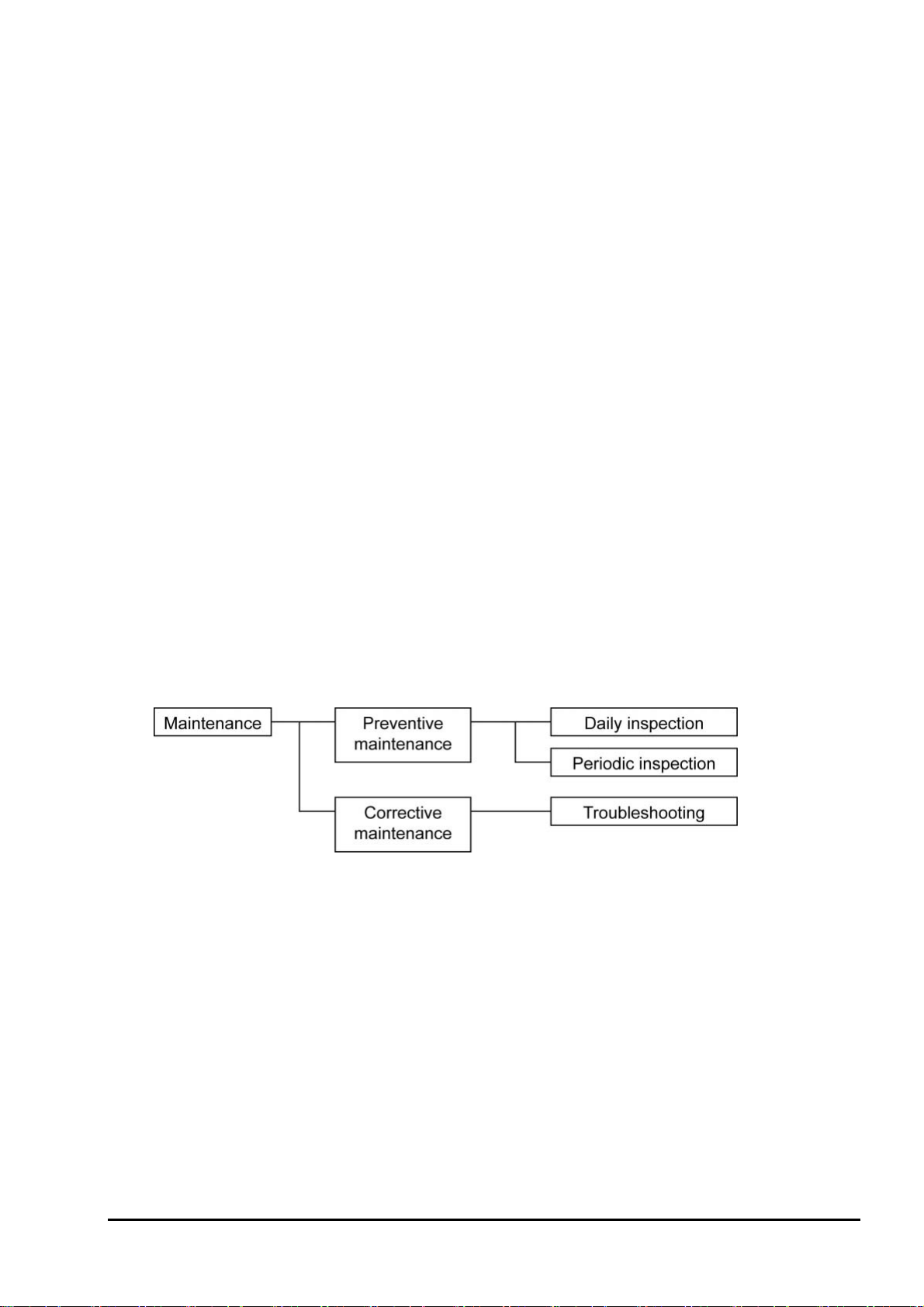
Maintenance can be divided into “preventive maintenance” and “corrective maintenance”. Preventive
maintenance can further classified into “daily inspection” and “periodic inspection”. Preventive maintenance
is achieved through systematic implementation of "daily inspection" and "periodic inspection".
(1) Daily inspection
Be sure to perform daily inspection prior to operation to check for any problem in daily operation. For the
specific items of daily inspection, refer to Chapter 9, “MAINTENANCE AND CHECK”.
(2) Periodic inspection
Periodic inspection is to replace limited-life parts before their service lives are over, thus preventing failure.
Inspection interval: 6 months to 12 months. If you are using the instrument under harsh environment, we
recommend you to shorten the inspection interval. For the specific items of periodic inspection, refer to
Chapter 9, “MAINTENANCE AND CHECK”.
(3) Corrective maintenance
Corrective maintenance is a measure to be taken after a trouble has occurred. Refer to 9.5 “Troubleshooting”.
If the measures mentioned in this instruction manual do not solve the problem, please contact our sales office
or service office.
INZ-TN2ZKMA-E
- v -
Page 7

8. Limited-life parts and consumable parts
This product contains the following limited-life parts and consumable parts which may affect the service life
of the product itself.
(1) LCD
Design life: approx. five years for continuous use
Symptoms of LCD screen's end-of-life: deterioration of display, backlight failure, etc.
Factors which affect LCD's life: temperature. The life is shortened by half when the temperature rises
by 10°C. (Arrhenius' law)
Replacement: Estimate the lifetime of LCD according to your operating environment, and have the
LCD replaced at appropriate time.
(2) Aluminum electrolytic capacitors
Design life: 5 years under general working conditions (annual average of ambient temperature: 30°C)
Symptoms when a capacitor loses its capacity: deterioration of power quality, malfunction
Factors which affect capacitor life: temperature. The life is shortened by half when the temperature
rises by 10°C. (Arrhenius' law)
Replacement: Estimate the lifetime of capacitor according to your operating environment, and have
the capacitor replaced or overhauled at appropriate time, at least once in 10 years.
Do not use capacitors beyond its lifetime. Otherwise, electrolyte leakage or depletion may cause odor, smoke,
or fire. Please contact Fuji Electric or its service providers when an overhaul is required.
9. Spare parts and accessories
Refer to “Checking of contents of the package” or Chapter 9, “MAINTENANCE AND CHECK” for details.
10. Period for repair and provision of spare parts after product discontinuation (maintenance period)
The discontinued models (products) can be repaired for five years from the date of discontinuation. Also,
most spare parts used for repair are provided for five years from the date of discontinuation. However, some
electric parts may not be obtained due to their short life cycle. In this case, repair or provision of spare parts
may be difficult even in the above period.
Please contact Fuji Electric or its service providers for further information.
- vi -
INZ-TN2ZKMA-E
Page 8

Contents
PREFACE ..........................................................................................................................................................i
SAFETY PRECAUTIONS ............................................................................................................................. ii
WARRANTY AND MAINTENANCE ...........................................................................................................iv
CHECKING OF CONTENTS OF THE PACKAGE .................................................................................... x
STORAGE CONDITIONS .............................................................................................................................. x
1. GENERAL .................................................................................................................................................... 1
1.1 Direct insertion type zirconia oxygen analyzer ........................................................................................ 1
2. OPERATING PARTS AND THEIR FUNCTIONS ................................................................................... 2
2.1 Outline Drawing ....................................................................................................................................... 2
2.2 Terminal block .......................................................................................................................................... 3
2.3 Didplay and operation panel ..................................................................................................................... 3
2.4 Internal constitution .................................................................................................................................. 4
3. INSTALLATION .......................................................................................................................................... 5
3.1 Installation site .......................................................................................................................................... 5
3.2 How to install the converter ...................................................................................................................... 6
3.2.1 Mounting on panel (ZKMA) ............................................................................................................. 6
3.2.2 Pipe mounting (ZKMA) ..................................................................................................................... 6
3.2.3 Mounting on panel (ZKMB) ............................................................................................................. 7
3.2.4 Pipe mounting (ZKMB) .................................................................................................................... 7
4. WIRING AND PIPING ................................................................................................................................ 8
4.1 Before wiring ............................................................................................................................................ 8
4.2 Wiring to terminals ................................................................................................................................... 9
4.2.1 Wiring to power supply and detector ................................................................................................. 9
4.2.2 Cable gland and input and output lines ............................................................................................ 10
4.2.3 Allocation of the terminal block ....................................................................................................... 11
4.3 Wiring and piping diagram ..................................................................................................................... 12
4.4 Handling of standard gas (An article on separate order) ........................................................................ 16
5. OPERATION .............................................................................................................................................. 17
5.1 Preparation for operation ........................................................................................................................ 17
5.2 Key operation flow diagram (outline) .................................................................................................... 19
5.3 Initial parameter value table ................................................................................................................... 23
5.3.1 Parameters related to measurement .................................................................................................. 23
5.3.2 Parameters related to calibration ...................................................................................................... 23
5.3.3 Parameters related to blowdown (displayed if the option is provided) ............................................ 24
5.3.4 Parameters related to maintenance ................................................................................................... 24
5.3.5 Other parameters .............................................................................................................................. 25
6. OPERATION START AND STOP .......................................................................................................... 27
6.1 Operation start ........................................................................................................................................ 27
6.2 Operation stop ......................................................................................................................................... 27
6.3 Actions during operation ......................................................................................................................... 28
6.4 Check the contents of display ................................................................................................................. 29
6.4.1 Check of state information ............................................................................................................... 29
6.4.2 Checking the error information ........................................................................................................ 30
6.4.3 Checking the alarm information ....................................................................................................... 30
6.5 Oxygen detector standard output voltage ............................................................................................... 31
INZ-TN2ZKMA-E
- vii -
Page 9

7. CALIBRATION ......................................................................................................................................... 32
7.1 Preparation ............................................................................................................................................. 32
7.2 Manual calibration ................................................................................................................................. 33
7.3 Auto calibration (option) ........................................................................................................................ 35
7.4 Remote calibration ................................................................................................................................. 37
7.5 All calibration (option) ........................................................................................................................... 39
8. BLOWDOWN (OPTION)......................................................................................................................... 40
8.1 Preparation for blowdown ...................................................................................................................... 40
8.2 Manual blowdown.................................................................................................................................. 40
8.3 Automatic blowdown ............................................................................................................................. 41
8.4 Remote blowdown ................................................................................................................................. 43
9. MAINTENANCE AND CHECK .............................................................................................................. 45
9.1 Checking ................................................................................................................................................ 45
9.2 Spare parts .............................................................................................................................................. 45
9.3 Replacement of fuse ............................................................................................................................... 46
9.4 Adjustment of monitor contrast .............................................................................................................. 47
9.5 Troubleshooting ..................................................................................................................................... 48
10. SETTING AND OPERATING OF PARAMETER ............................................................................... 50
10.1 Measured menu .................................................................................................................................... 50
10.1.1 Display range setting screen .......................................................................................................... 50
10.1.2 Decimal point position setting screen ............................................................................................ 51
10.1.3 Full scale setting screen ................................................................................................................. 52
10.1.4 Setting screen for calculation time of maximum and minimum values appears ........................... 53
10.2 Calibration menu .................................................................................................................................. 54
10.2.1 Automatic calibration setting (option) ........................................................................................... 54
10.2.2 Date and time for starting automatic calibration (option) ............................................................. 55
10.2.3 Cycle time setting of automatic calibration (option) ..................................................................... 56
10.2.4 Performing all calibration (option) ................................................................................................ 57
10.2.5 Performing a manual span calibration ........................................................................................... 58
10.2.6 Performing a manual zero calibration ........................................................................................... 59
10.2.7 Calibration gas setting ................................................................................................................... 60
10.2.8 Calibration waiting setting (option) ............................................................................................... 61
10.2.9 Calibration error clear ................................................................................................................... 62
10.2.10 Operation setting screen of calibration range .............................................................................. 63
10.3 Blowdown menu (option) .................................................................................................................... 64
10.3.1 Automatic blowdown setting ......................................................................................................... 64
10.3.2 Date and time setting of automatic blowdown .............................................................................. 65
10.3.3 Automatic blowdown cycle setting ............................................................................................... 66
10.3.4 Procedure for setting blowdown time ............................................................................................ 67
10.3.5 Perfoming manual blowdown ........................................................................................................ 68
10.4 Maintenance menu ............................................................................................................................... 69
10.4.1 Error log display ............................................................................................................................ 69
10.4.2 Clearing error logs ......................................................................................................................... 71
10.4.3 Alarm log display .......................................................................................................................... 72
10.4.4 Clearing alarm logs ....................................................................................................................... 73
10.4.5 Performing a manual sensor check ................................................................................................ 74
10.4.6 Maintenance mode setting ............................................................................................................ 75
10.4.7 Password setting ............................................................................................................................ 76
10.4.8 PID auto tuning ............................................................................................................................. 77
10.5 Parameter menu ................................................................................................................................... 78
10.5.1 Current date and time setting ......................................................................................................... 78
10.5.2 Contact input setting ...................................................................................................................... 79
10.5.3 Selection of alarm contact output .................................................................................................. 80
10.5.4 High limit setting of oxygen concentration ................................................................................... 81
- viii -
INZ-TN2ZKMA-E
Page 10

10.5.5 Lower limit setting of oxygen concentration ................................................................................. 82
10.5.6 HH limit setting of oxygen concentration ...................................................................................... 83
10.5.7 LL limit setting of oxygen concentration ....................................................................................... 84
10.5.8 Hysteresis Setting ........................................................................................................................... 85
10.5.9 Hold treatment setting (maintenance hold) ................................................................................... 87
10.5.10 Hold value setting (maintenance hold) ........................................................................................ 88
10.5.11 Setting of hold setting value (maintenance hold) ........................................................................ 89
10.5.12 Setting of measurement recovery time (maintenance hold) ........................................................ 90
10.5.13 Hold treatment setting (error hold).............................................................................................. 91
10.5.14 Hold value setting (error hold) ..................................................................................................... 92
10.5.15 Setting of hold setting value (error hold) .................................................................................... 93
10.5.16 Setting of key lock ....................................................................................................................... 94
10.5.17 Setting of automatic OFF time ..................................................................................................... 95
10.5.18 Station number setting .................................................................................................................. 96
10.5.19 Adjustment screen for analog output 0% ..................................................................................... 97
10.5.20 Adjustment screen for analog output 100% ................................................................................. 98
10.5.21 Fuel coefficient setting (option) ................................................................................................... 99
10.6 Factory menu ...................................................................................................................................... 100
10.6.1 Password setting screen ................................................................................................................ 100
11. SPECIFICATIONS ................................................................................................................................ 101
11.1 Specifications ...................................................................................................................................... 101
11.2 Code symbols ...................................................................................................................................... 104
INZ-TN2ZKMA-E
- ix -
Page 11

CHECKING OF CONTENTS OF THE PACKAGE
Check that all of the following are contained in the delivered package.
(1) Zirconia Oxygen Analyzer Converter main unit 1 unit
(2) Accessories 1 set (Refer to the table below.)
Table 1 Standard accessories
No. Item Q'ty Remarks
1 Fuse 2 250 V T 2.5 A
2 Ferrite core 1 For power cable
3 Instruction manual 1
Instruction manual (RS485
4
communication or HART
communication)
5 Mounting bracket 1 set
Japanse, English, or Chinese (depends on the specification)
When you specified RS485 communication or HART
1
communication.
Language: Japanse, English, or Chinese (as specified)
For panel mount version: M8 sems screw (stainless
steel), 4 pcs
For pipe mount version: U bolt (stainless steel ), 2 pcs
: M8 nut, washer (stainless steel) 4 pcs
: support 2 pcs
STORAGE CONDITIONS
Store the unit in a location that meets the following conditions:
(1) Vibration, dust, dirt, and humidity are minimal.
(2) A place not subjected to radiated heat from a heating furnace, etc.
(3) The atmosphere is non-corrosive.
(4) The ambient temperature is within the range from -30°C through 70°C (no condenstaion) and the
ambient humidity is 95%RH or lower.
- x -
INZ-TN2ZKMA-E
Page 12

1. GENERAL
This manual describes the installation, operation, and the maintenance of the zirconia oxygen analyzer converter. Read it carefully before using the converter. For the detector, flow guide tube and ejector used with
the converter, refer to relevant instruction manuals.
1.1 Direct insertion type zirconia oxygen analyzer
The direct insertion type zirconia oxygen analyzer consists of a direct insertion type zirconia detector (type
ZFK) and converter (type ZKM).
The analyzer intended for the measurement of oxygen concentration in exhaust gas is used for combustion
control.
Caution
Power voltage for the converter must conform to that for the detector to be connected. Don’t use any
power voltage different from the power specifications of the detector. Otherwise it may result in damage
to the detector.
100/120V AC50/60Hz for ZFK8R1
200/240V AC50/60Hz for ZFK8R3
Operating environment
1) Operating temperature: -20 to 55°C
2) Operating humidity: 95%RH or less, non condensing
3) Power voltage: 100 to 120V AC 50/60Hz or 200 to 240V AC 50/60Hz
4) Pollution degree: 2
5) Installation category: II
6) Altitude: up to 2000m
INZ-TN2ZKMA-E
- 1 -
Page 13
2. OPERATING PARTS AND THEIR FUNCTIONS
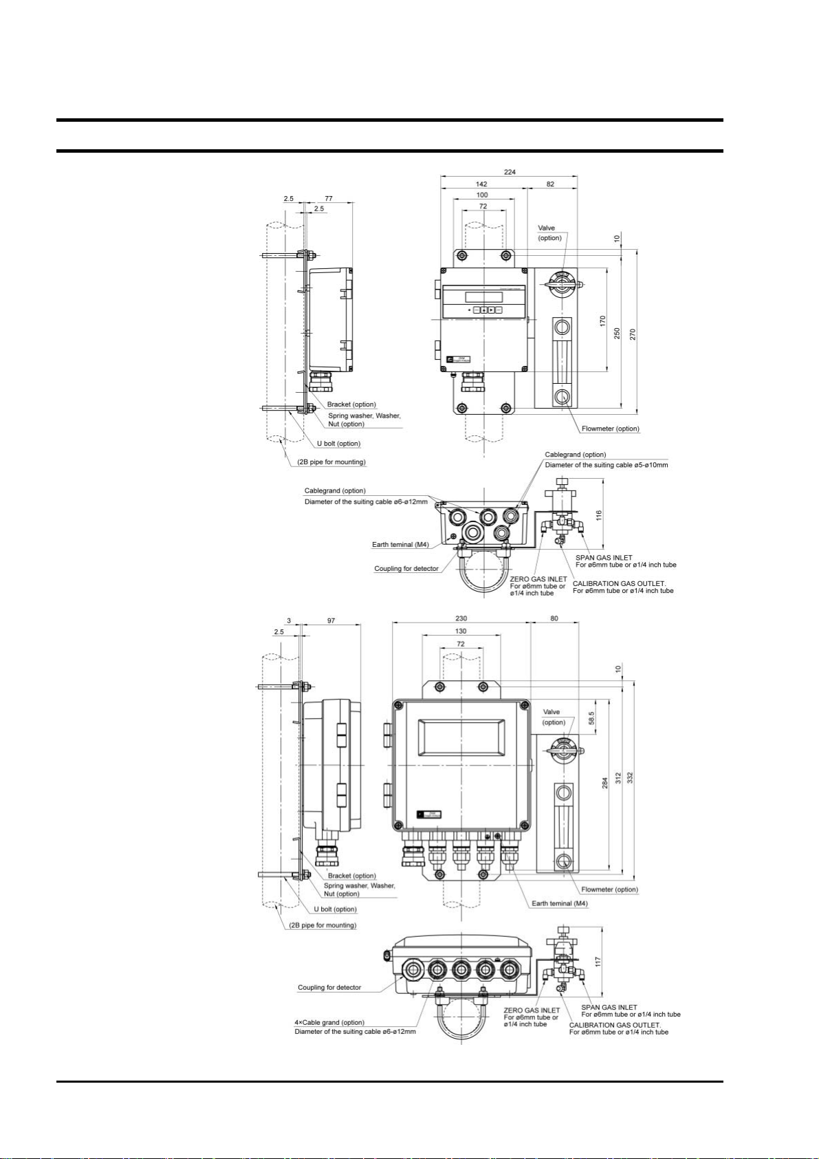
2.1 Outline Drawing
(1) ZKMA
(2) ZKMB
- 2 -
INZ-TN2ZKMA-E
Page 14
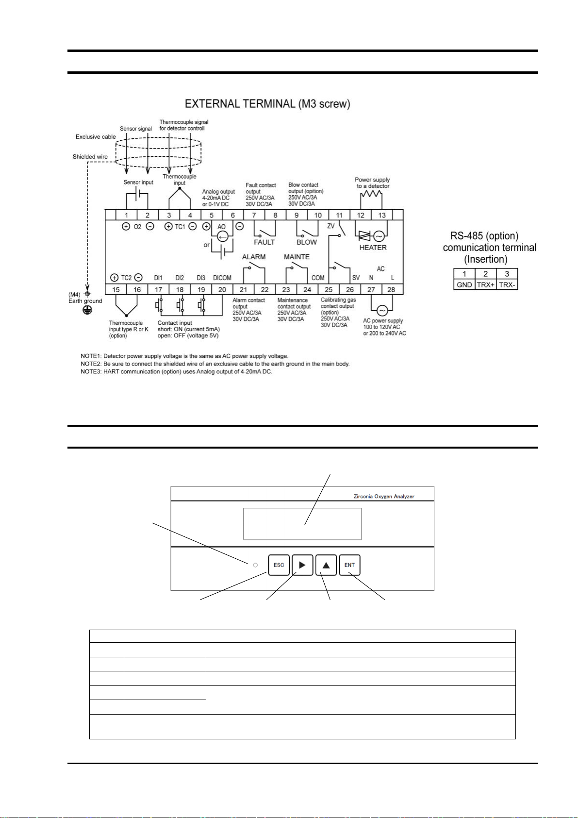
2.2 Terminal block
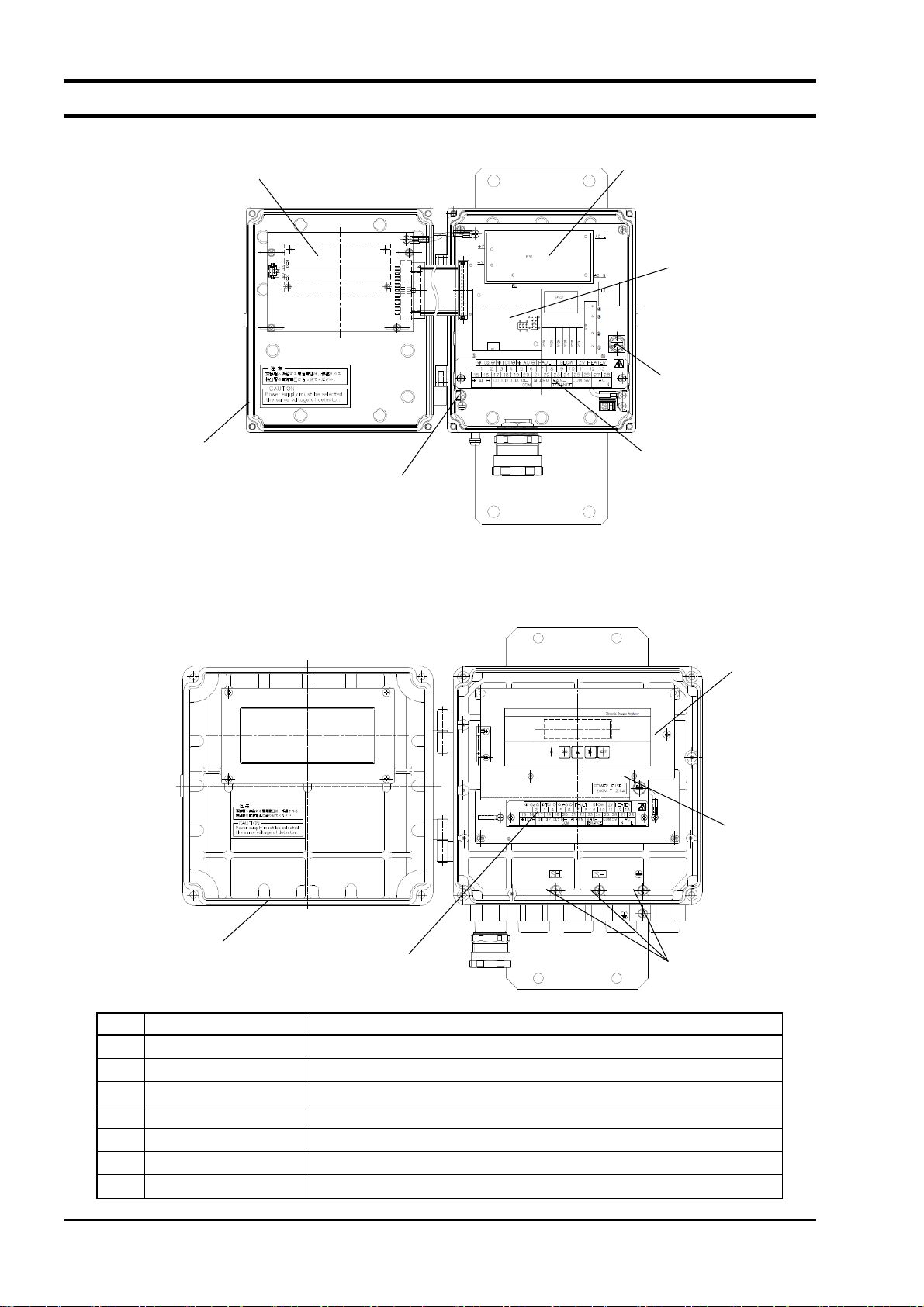
2.3 Didplay and operation panel
LED
①
ESC key
⑥
⑤
Digit key
No. Name Description
Display unit
①
LED Lights during power supply.
②
ESC key Used to return to the previous screen or exit the setting.
③
Digit key
④
Up key
⑤
ENT key Used to determine the setting values or to start calibration or
⑥
Displays the concentration value and setting values.
Used to change the setting values.
other operations.
④
Display
①
Up key
ENT key
③
INZ-TN2ZKMA-E
- 3 -
Page 15
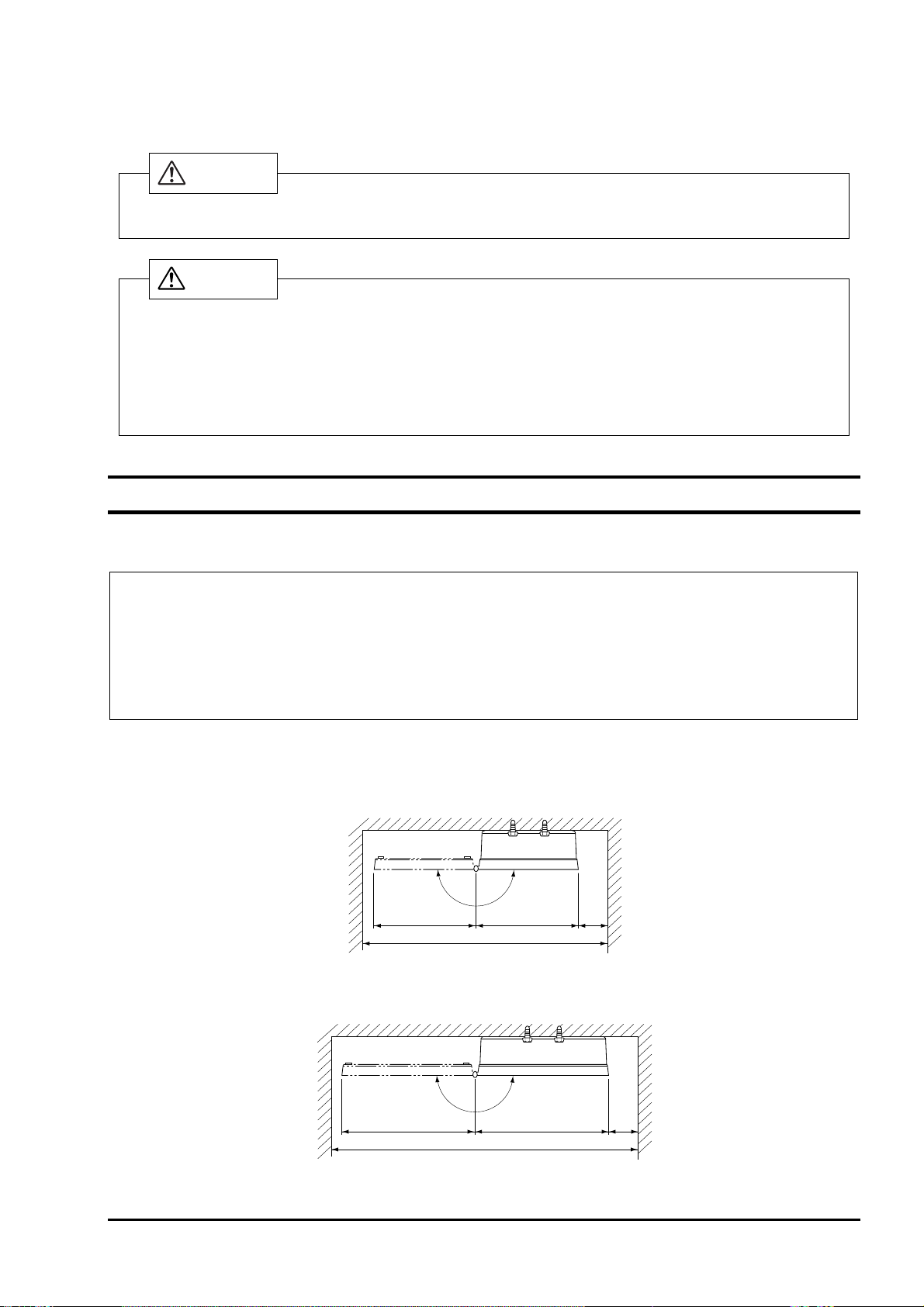
2.4 Internal constitution
(1) ZKMA
I/O board
CPU board
②
①
Communication
③
board (optional)
Fuse
⑦
Packing
④
Earth terminal
⑥
⑤
Terminal block
(2) ZKMB
You can see the CPU board, the I/O board, and the communication board (optional) if you remove the M3
screw and open the inner cover.
Packing
⑦
No. Name Description
CPU board The liquid crystal display and the memory circuit are installed.
①
I/O board The input/output circuit and the power circuit are installed.
②
Communication board RS485 communication board or HART communication board is installed.
③
Fuse Protects the CPU board and the I/O board from over-current.
④
Terminal block
⑤
Earth terminal Used as frame gland (FG).
⑥
Case packing Protects electrical components from water and dust.
⑦
Terminal block
⑤
Terminals for power cable, detector cable, and input/output cables.
Earth terminal
⑥
M3 screw
Fuse
④
- 4 -
INZ-TN2ZKMA-E
Page 16
3. INSTALLATION
DANGER
This unit is not explosion-proof type. Do not use it in an atmosphere of explosive gases. Otherwise
serious accidents such as explosion or fire may result.
For installation, observe the rule on it given in the instruction manual and select a place where the
weight of converter can be endured. Installation at an unsuited place may cause turnover or fall and
there is a risk of injury.
Before transport, fix the door so that it will not open. Otherwise, the casing may be separated and fall
to cause an injury.
During installation work, care should be taken to keep the unit free from entry of cable chips or other
foreign objects. Otherwise, it may cause fire, failure or malfunction.
CAUTION
3.1 Installation site
Install the converter in a place that satisfies the following conditions.
(1) Space for periodic inspection and wiring work is available.
(2) Vibration, dust, dirt, and humidity are minimal.
(3) A place not subjected to radiated heat from a heating furnace, etc.
(4) The atmosphere is non-corrosive.
(5) Away from electrical devices that may cause noise trouble (such as motor and transformer), and
equipment that may cause electromagnetic or electrostatic induction trouble.
(6) A place where ambient temperature and humidity are -20 to +55°C and 95%RH or less.
Secure at least 100 mm of space between the converter and nearby wall. Also secure a space of opening the
front cover for maintenance.
Secure a cable wiring space under the case.
E
P
O
400 or more
N
147147
100
or
more
Unit: mm
Top view of mounting (ZKMA)
INZ-TN2ZKMA-E
N
E
P
O
240
580 or more
240
Top view of mounting (ZKMB)
- 5 -
100
or
more
Unit: mm
Page 17
3.2 How to install the converter
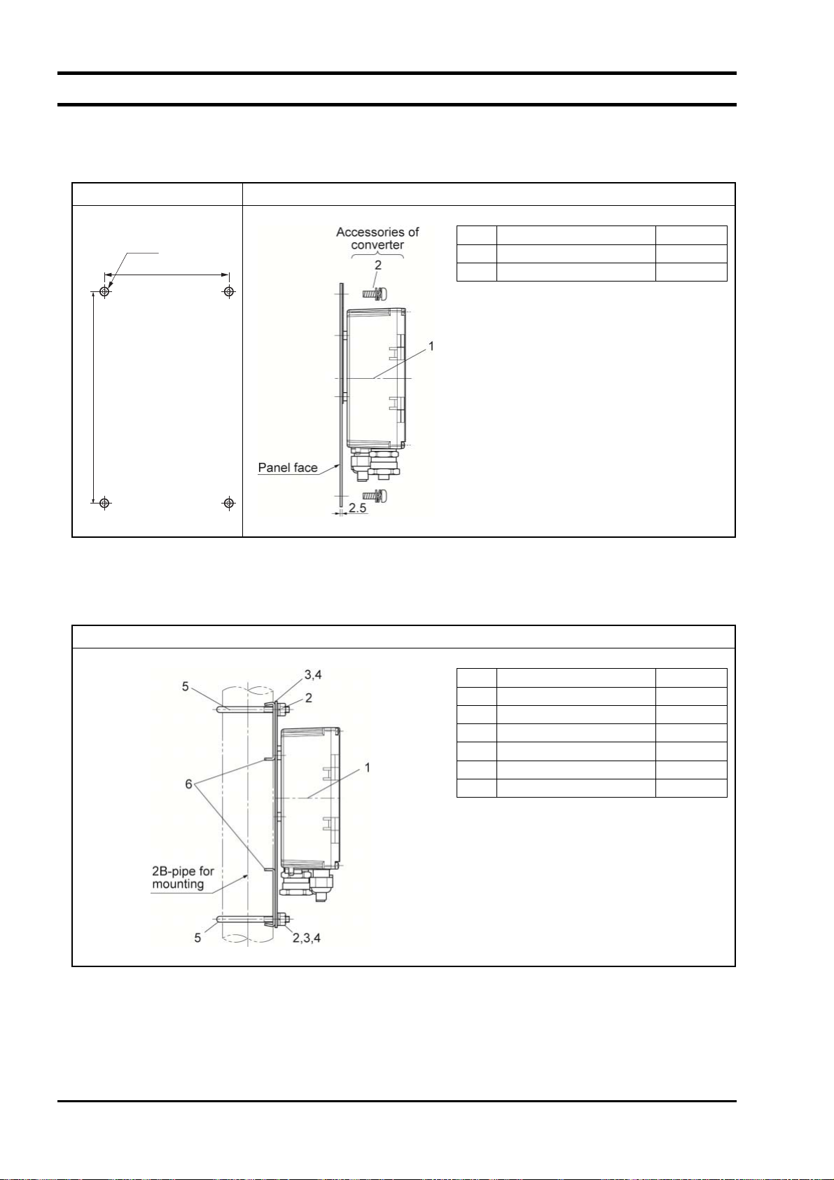
3.2.1 Mounting on panel (ZKMA)
Mounting dimensions Installation
4-M8
72
250
No. Name Quantity
Code Standard tightening torque
Unit: mm
1 Converter 1
2 Sems screw (M8×12) 4
M8
12.5 [N・m]
3.2.2 Pipe mounting (ZKMA)
Installation
No. Name Quantity
1 Converter 1
2 Hexagon nut (M8) 4
3 Spring washer (M8) 4
4 Plain washer (M8) 4
5 U bolt (M8) 2
6 Support panel 2
Code Standard tightening torque
M8
12.5 [N・m]
- 6 -
INZ-TN2ZKMA-E
Page 18
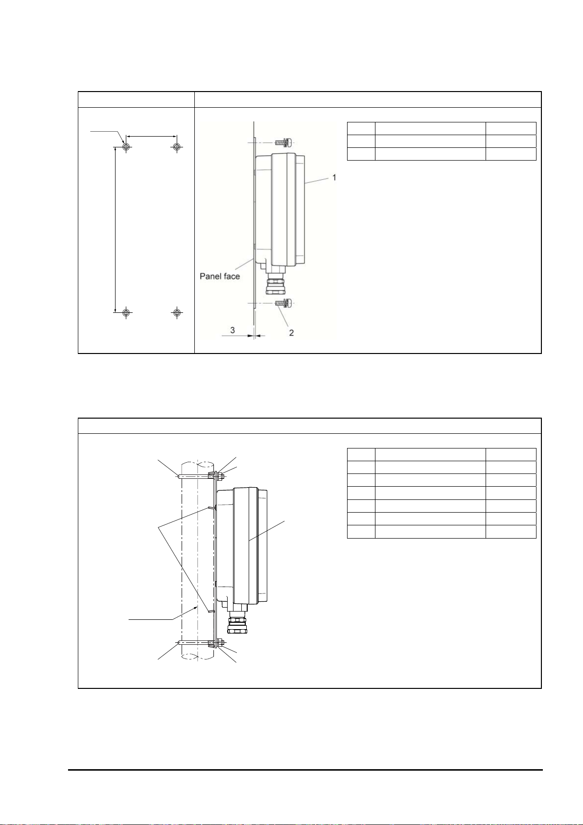
3.2.3 Mounting on panel (ZKMB)
Mounting dimensions Installation
No. Name Quantity
4-M8
72
Code Standard tightening torque
312
Unit: mm
1 Converter 1
2 Sems screw (M8×12) 4
M8
12.5 [N・m]
3.2.4 Pipe mounting (ZKMB)
5
6
Pipe for
mounting
5
3,4
2
2
3,4
Installation
1
No. Name Quantity
1 Converter 1
2 Hexagon nut (M8) 4
3 Spring washer (M8) 4
4 Plain washer (M8) 4
5 U bolt (M8) 2
6 Support panel 2
Code Standard tightening torque
M8
12.5 [N・m]
INZ-TN2ZKMA-E
- 7 -
Page 19
4. WIRING AND PIPING
: Wiring work must be carried out with all power supplies turned off. Otherwise electric
CAUTION
shock may result.
: Be sure to ground the Converter. (Class D grounding)
4.1 Before wiring
(1) Power voltage for the converter must conform to that for the detector to be connected.
(2) Power supply wiring
Use 1.25sq 600V vinyl insulated cable (JISC3307) or equivalent as power supply cable.
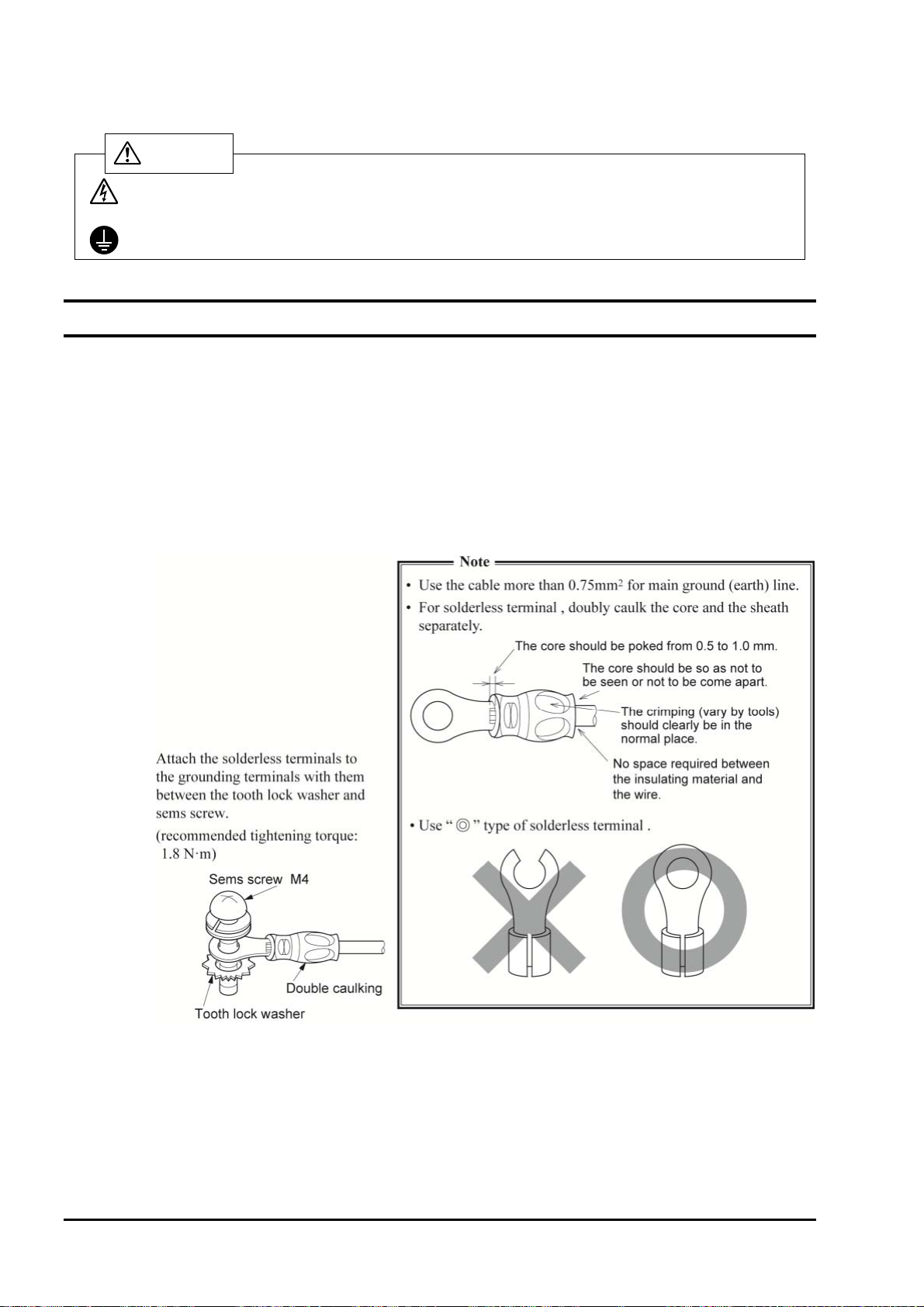
Use the main ground wire longer than the L1 and L2 lines.
Fix the part of the AC cable sheath that is more inner than the cord bushing by 3 mm or more.
Use a solderless terminal for the end of the AC cable. For the main ground wire, use the solderless
terminal whose core wire and sheath are caulked separately (double caulking).
Connect the ground wire to the following:
M4 screw / round terminal of the main ground wire / tooth lock washer / casing
(3) Provide adequate protection of the exclusive cable (6 cores in total), which connects the detector to
converter, using wire protection tube, etc. Separate these cables from the power cable (noise prevention).
(4) Keep the wire for output signals as far as possible (more than 30cm) from the power line and heavy
current lines to prevent induced noise. Also, wherever possible use a shielded cable and earth one
point of the shield.
Note) For connection of the lines to the external terminals, use of ring crimp solderless terminal
with insulation sleeve is recommended.
- 8 -
INZ-TN2ZKMA-E
Page 20
4.2 Wiring to terminals
4.2.1 Wiring to power supply and detector
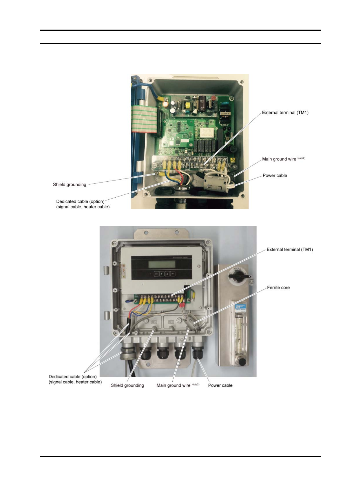
(1) <ZKMA>
(2) <ZKMB>
Note 1: Fix the exclusive cable (O
that its sheath is 10 mm or less.
When attaching the nut, turn it by hand until it does not move and then tighten it with a spanner
by about 1/4 turn.
Note 2: Wire a protective earth to earth terminal of above figure. (Class D, grounding resistance: 100Ω
or less)
Note 3: Wind the power cable around the ferrite core twice.
INZ-TN2ZKMA-E
sensor input / O2 sensor thermocouple input) with the cable gland so
2
- 9 -
Page 21
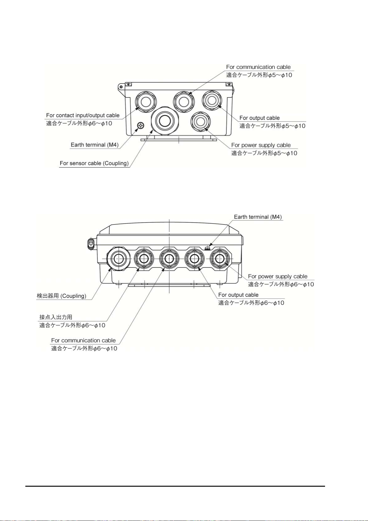
4.2.2 Cable gland and input and output lines
(1) <ZKMA>
(2) <ZKMB>
- 10 -
INZ-TN2ZKMA-E
Page 22
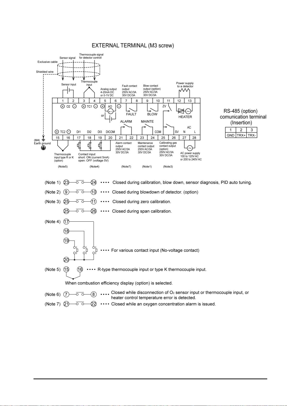
4.2.3 Allocation of the terminal block
INZ-TN2ZKMA-E
- 11 -
Page 23
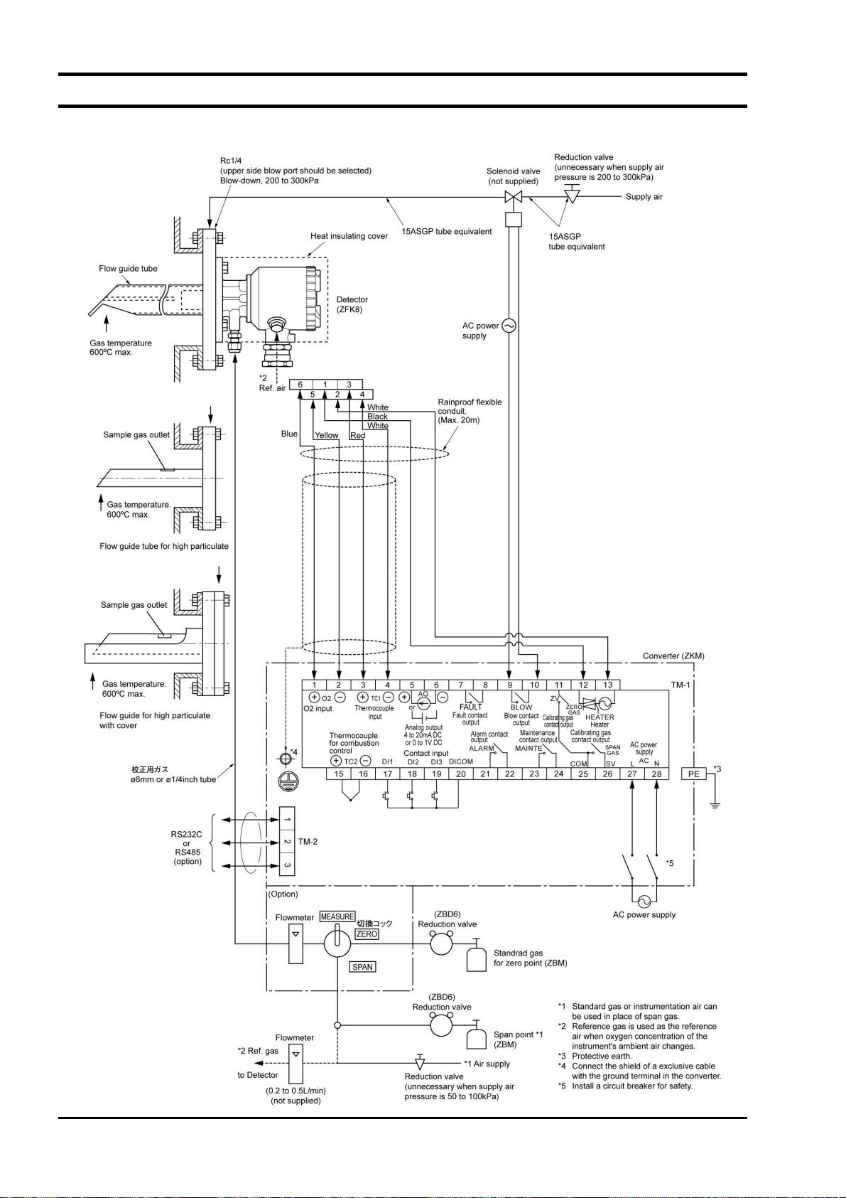
4.3 Wiring and piping diagram
4.3.1.1 Flow guide tube system
- 12 -
INZ-TN2ZKMA-E
Page 24
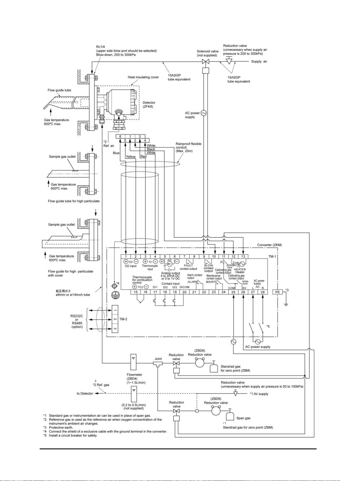
4.3.1.2 Flow guide tube system (with valve)
INZ-TN2ZKMA-E
- 13 -
Page 25
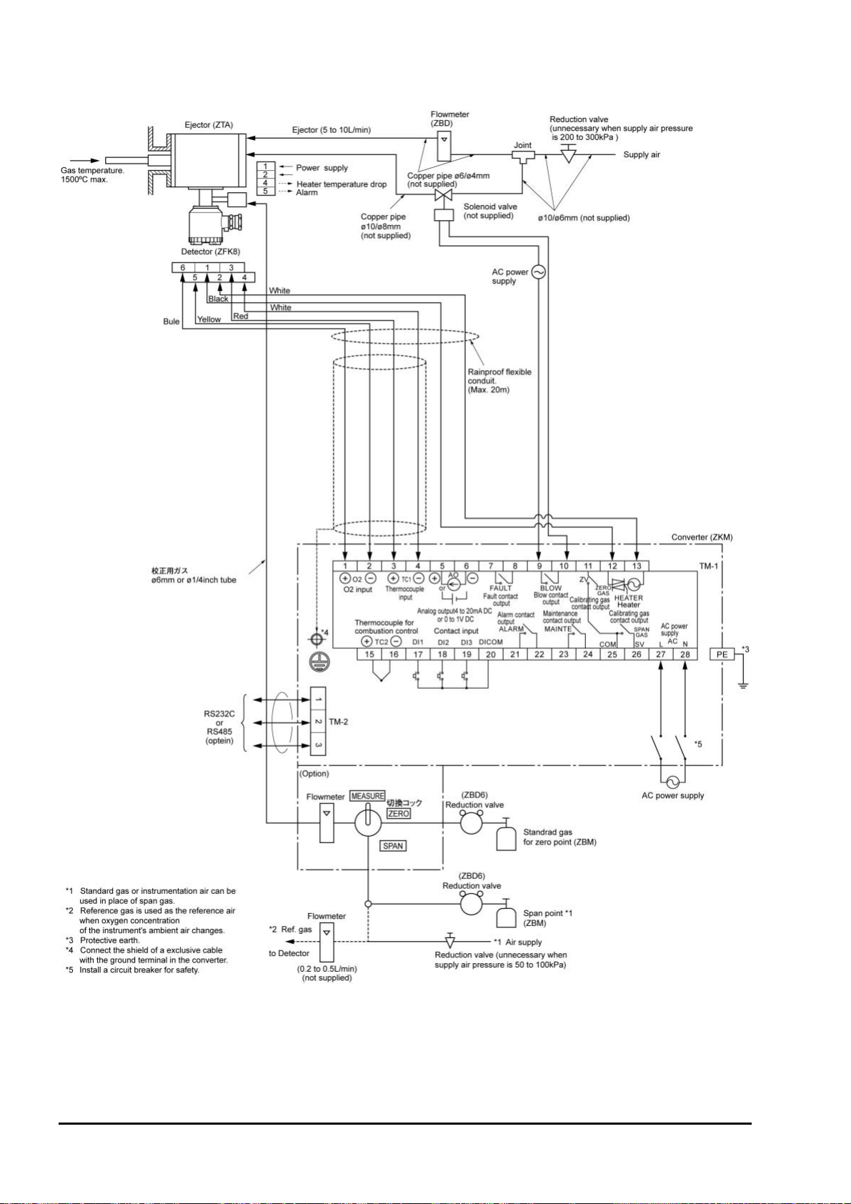
4.3.1.3 Ejector system
- 14 -
INZ-TN2ZKMA-E
Page 26
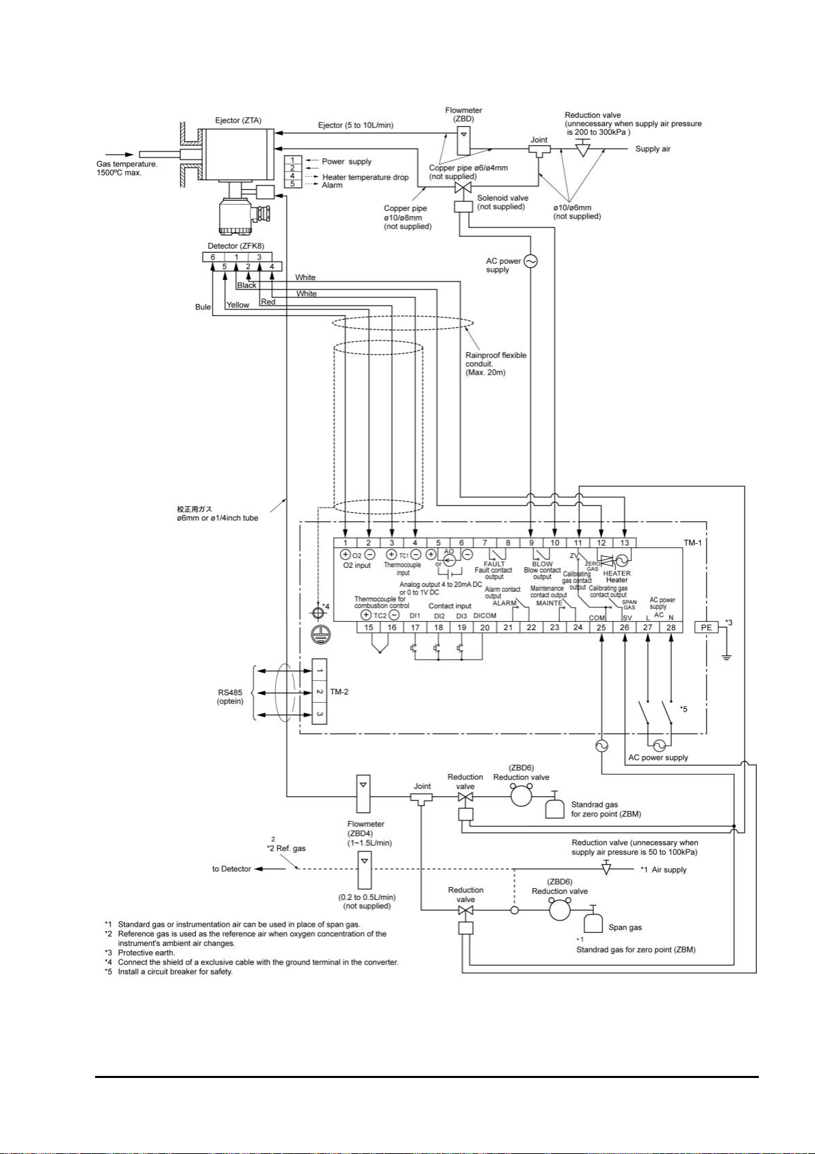
4.3.1.4 Ejector system (with valve)
INZ-TN2ZKMA-E
- 15 -
Page 27
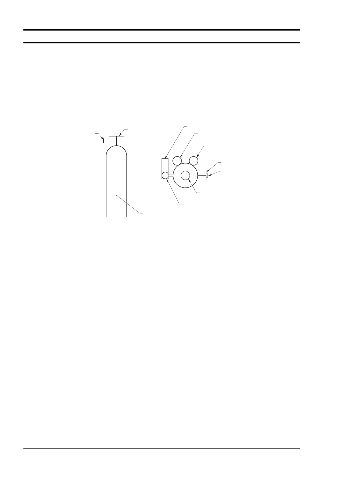
4.4 Handling of standard gas (An article on separate order)
4.4.1.1 Operation
(1) Make sure the handle is closed on the high pressure gas container, then detach the cap nut.
(2) Attach the high pressure gas container using the cap nut with packing of the pressure reduction valve.
(3) Make sure the secondary pressure adjusting valve is turned fully counterclockwise (pressure not ap-
plied) and the outlet needle is turned fully clockwise (closed), then open the handle.
(4) Turn the secondary pressure adjusting valve clockwise and set to the normal value of 20 to 30 kPa,
then open the outlet needle slowly to allow the gas to flow.
Pressure reduction valve
(WR11FS)
Fow rater
Secondary
pressure meter
Primary pressure
meter
Cap nut
Handle
Cap nut
Packing
Secondary pressure
adjusting valve
Outlet needle
High pressure
gas container
4.4.1.2 Piping
(1) The gas outlet of the pressure reduction valve is of Rc 1/4 (internal thread).
Prepare the joint and tube (such as 6/ 4 teflon tube).
4.4.1.3 Caution
(1) Fasten securely, so there is no gas leakage from the pressure reduction valve connection or from
threaded part of the joint.
(2) Store high pressure gas containers in a place protected from direct sunlight and rain.
(3) After use, be sure to close the handle.
- 16 -
INZ-TN2ZKMA-E
Page 28
5. OPERATION
5.1 Preparation for operation
Preparation can be performed after installation or on the bench.
(1) Wiring check (Refer to “4.2”, “4.3”)
(2) Confirmation of the power supply specifications (Please check the main power supply and the
power supply voltage specification of the detector.)
(3) Power ON.
The analyzer turns on when the power is supplied. (Refer to “2.4”)
OXYGEN ANALYZER
VER . YY/MM
WARM-UP
HEATER 234 °C
The message shown left appears on the LCD screen.
After about 6 seconds, the display is automatically switched to the
warming-up screen.
(4) Warm-up
Warm-up takes 10 minutes or less. Then the analyzer starts temperature control for the detector
ZFK.
Note 1: If the temperature control completes within 10 minutes, the analyzer stops warm-up to
start operation. When you first use the analyzer, proceed to the step 5 “PID auto tuning”.
Note 2: Even if the temperature control does not complete within 10 minutes, the analyzer stops
warm-up to start operation, however, for 7 minutes after the warm-up stoped, the analyzer
cannot detect the error of the heater temperature nor display it. (Carry out the step 5 “PID
auto tuning” during this period.)
(5) PID auto tuning
When you first use the analyzer, perform the PID auto tuning within 7 minutes after the stop of
warm-up, in the state that the the detector ZFK is connected. Refer to Chapter 10 for the
procedures of the PID auto tuning. When the PID auto tuning is finished, the analyzer perform
warm-up again to check if tempertature control is possible, and then starts operation.
(6) Parameter setting
Move to each Menu with reference to the paragraph “5.2 Key operation flow diagram (outline)”,
and set a necessary parameter. Refer to the paragraph “5.3 Initial parameter value table”.
If you need to change a parameter, refer to the “Chapter 10”.
(7) Calibration
At the first operation, perform manual calibration after warm-up using a calibration gas.
Refer to “chapter 7” for calibration procedures.
INZ-TN2ZKMA-E
- 17 -
Page 29

(8) Auto calibration (option)
Automatic calibration may be performed at specified time intervals.
Refer to “7.3” for automatic calibration settings.
(9) Blowdown (option)
A flow guide tube blowdown feature prevents the flow guide tube from clogging due to dust in
the gas stream.
Refer to “chapter 8” for operation procedures.
Operation
- 18 -
INZ-TN2ZKMA-E
Page 30
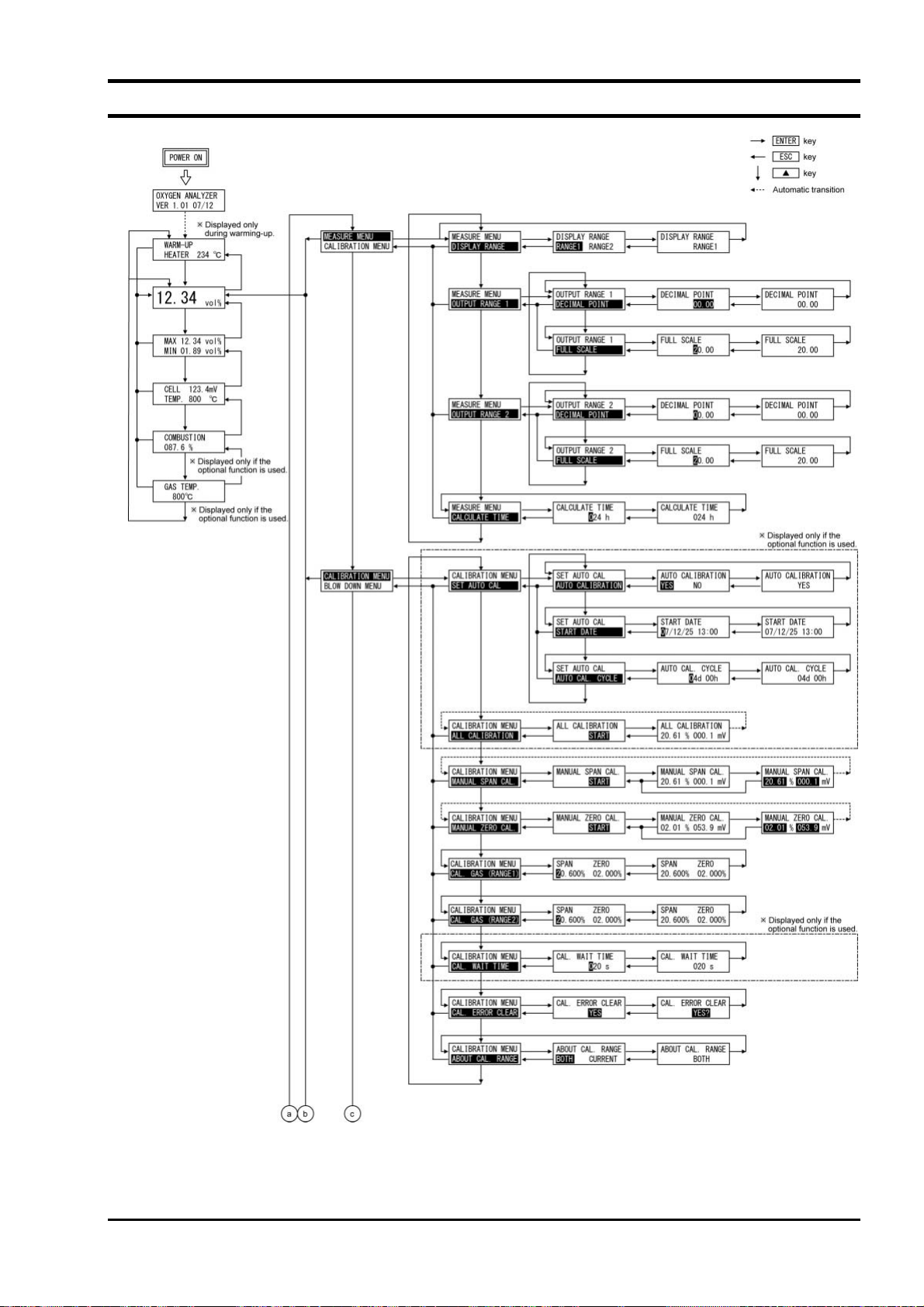
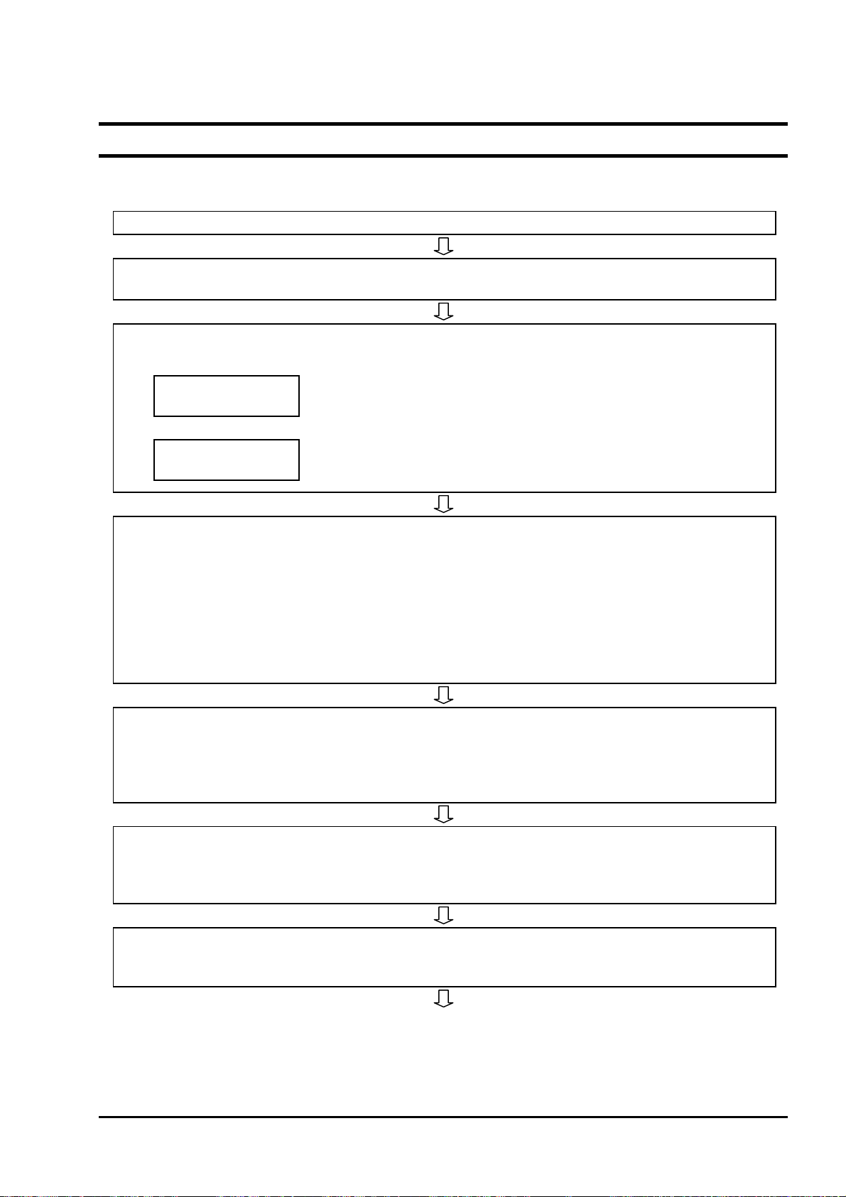
5.2 Key operation flow diagram (outline)
INZ-TN2ZKMA-E
- 19 -
Page 31

- 20 -
INZ-TN2ZKMA-E
Page 32

INZ-TN2ZKMA-E
- 21 -
Page 33

- 22 -
INZ-TN2ZKMA-E
Page 34
5.3 Initial parameter value table
5.3.1 Parameters related to measurement
Parameter setting Displayed message Range Initial value
Display range
DISPLAY RANGE
RANGE1 RANGE2
Range1 or Range2 Range-1 10.1.1
Reference
paragraph
Decimal point position
Range1
Range2
Full scale
Range1
Range2
Calculation time of maximum and minimum values
DECIMAL POINT
00.00
FULL SCALE
25.00
CALCULATE TIME
024 h
[00.00]
[0.000]
2 to 50 in 1 vol% steps 25.00 vol% 10.1.3
0 to 240 hour in 1-hour
steps
[00.00] 10.1.2
24 hour 10.1.4
5.3.2 Parameters related to calibration
Parameter setting Displayed message Range Initial value
Auto calibration function
(Displayed if the option is
provided.)
Date and time for starting
automatic calibration
(Displayed if the option is
provided.)
Automatic calibration
cycle time
(Displayed if the option is
provided.)
Calibration gas concentration-1
calibration gas concentration-2
Calibration wait time
AUTO CALIBRATION
YES NO
START DATE
99/01/01 00:00
AUTO CAL. CYCLE
07d 00h
SPAN ZERO
20.600% 01.000%
CAL. WAIT TIME
020 s
YES or NO
Date and time in the future in the calendar
00d 00h to 99d23h
(h: 00 to 23)
Span:
00.010 to 50.000 vol%
Zero:
00.010 to 25.000 vol%
in 0.001 vol% steps
10 to 999 sec.
in 1 sec. steps
Invalid
(Auto calibration
function: Invalid)
99/01/01 00:00 10.2.2
07d 00h 10.2.3
Span:
20.600 vol%
Zero:
01.000 vol%
300 sec. 10.2.8
Reference
paragraph
10.2.1
10.2.7
Calibration range setting
INZ-TN2ZKMA-E
ABBOUT CAL. RANGE
BOTH CURRENT
Set calibration range
Current or both range
- 23 -
BOTH 10.2.10
Page 35

5.3.3 Parameters related to blowdown (displayed if the option is provided)
Parameter setting Displayed message Range Initial value
Automatic blowdown
function
BLOW DOWN
YES NO
YES or NO
NO
(The automatic
blowdown function is invalid.)
Date and time for starting
automatic blowdown
START DATE
99/01/01 00:00
Date and time in the future in the calendar
99/01/01 00:00 10.3.2
Automatic blowdown
cycle time
AUTO BLOW CYCLE
24h 00m
00h 00m to 99h 59m
(m: 00 to 59)
24h 00m 10.3.3
Blowdown time
BLOW DOWN TIME
030 s
0 to 999 sec. in 1 sec.
steps
30 sec. 10.3.4
Reference
paragraph
10.3.1
5.3.4 Parameters related to maintenance
Parameter setting Displayed message Range Initial value
Maintenance mode
Password
MAINTENANCE MODE
YES NO
NEW PASSWORD
0123
YES or NO NO 10.4.6
0000 to 9999 0000 10.4.7
Reference
paragraph
- 24 -
INZ-TN2ZKMA-E
Page 36

5.3.5 Other parameters
Parameter setting Displayed message Range Initial value
Current date and time
Contact inputs 1 to 3
Alarm contact output
Upper limit of oxygen
concentration
Range-1
Range-2
Lower limit of oxygen
concentration
Range-1
Range-2
Upper 2 limit of oxygen
concentration
Range-1
Range-2
Lower 2 limit of oxygen
concentration
Range-1
Range-2
Hysteresis
(Oxygen concentration
alarm)
Range-1
Range-2
Analog output hold function
Maintenance hold
Output value of analog
output hold
Maintenance hold
Setting the value of analog output hold
Maintenance hold
Error hold
Error hold
Error hold
DATE SET
00/00/01 00:00
DI 1
NONE
DO ALARM SET
ALARM NONE
HIGH ALARM
50.000 vol%
LOW ALARM
00.020 vol%
H-HIGH ALARM
55.000 vol%
L-LOW ALARM
00.010 vol%
HYSTERESIS
10 %
OUTPUT HOLD
YES NO
OUTPUT SELECT
0%
HOLD VALUE
000 %
Date and time in the calendar
DI1 to DI3
[NONE]
[BLOW DOWN ON]
[HEATER OFF]
[PROHIBIT CAL.]
[REMOTE CAL.]
[REMOTE HOLD]
[CALCULATE REST]
[OUTPUT RANGE]
[ALARM NONE]
[HIGH ALARM]
[LOW ALARM]
[H-HIGH ALARM]
[L-LOW ALARM]
[H/L ALARM]
[HH/LL ALARM]
0.001 to 55.000 vol% in
0.001 vol% steps
0.001 to 55.000 vol% in
0.001 vol% steps
0.001 to 55.000 vol% in
0.001 vol% steps
0.001 to 55.000 vol% in
0.001 vol% steps
0 to 20 % in 1 % steps 10 % 10.5.8
YES or NO
[0 %] (4 mA/0V)
[100 %] (20 mA/1V)
[Last output value]
[Setting value]
0 to 100 % in 1 % steps 0 %
(14/01/01/ 00:00) 10.5.1
DI1
[NONE]
DI2
[NONE]
DI3
[NONE]
[ALARM NONE] 10.5.3
50.000 vol% 10.5.4
00.020 vol% 10.5.5
55.000 vol% 10.5.6
00.010 vol% 10.5.7
NO
(Analog output
hold function is
invalid.)
[0 %](4 mA/0V)
Reference
paragraph
10.5.2
10.5.9
10.5.13
10.5.10
10.5.14
10.5.11
10.5.15
INZ-TN2ZKMA-E
- 25 -
Page 37

Parameter setting Displayed message Range Initial value
Measurement recovery
time
Key lock function
MEAS. WAIT TIME
010 s
KEY LOCK
YES NO
0 to 300 sec. in 1 sec.
steps
YES or NO
10 sec. 10.5.12
No
(Key lock function is invalid.)
Automatic OFF time
BACKLIGHT TIME
10 m
0 to 99
in 1-minute steps
10 minutes 10.5.17
Station No.
STATION NO
01
0 to 99 01 10.5.18
FUEL COEFFICIENT
FUEL COEFF.
0.70
0.00 to 1.99 0.70 10.5.21
Reference
paragraph
10.5.16
- 26 -
INZ-TN2ZKMA-E
Page 38

6. OPERATION START AND STOP
6.1 Operation start
After correct wiring and piping has been completed, turn on the converter to start measurement.
Note: 10 min. of warm-up time is necessary after power ON.
Caution of before starting operation
(1) Furnace operation should be started after an elapsed time of 10 minutes from the point of turn-
ing ”ON” the power supply of this unit
(2) When a detector is to be installed in a furnace already in operation, take care to blow out harmful
gas from the furnace and then install the fully warmed up detector quickly.
(3) Control of detector temperature may get unstable depending on the ambient temperature, power
supply voltage, and other conditions. In such a case (especially when you first use the analyzer),
perform PID auto-tuning after the stop of warm-up (Refer to 10.4.8 PID auto tuning).
6.2 Operation stop
6.2.1.1 When a process (furnace etc.) is to be shutdown for a short time i.e. a week
or so
It is strongly recommended to keep the detector in operation to avoid possible deterioration of platinum electrodes in the detector and detector break-down due to repetition of power ON-OFF in a moisture absorption
state.
In case of the detector with an ejector (option), shutdown the air source.
6.2.1.2 When a process (furnace etc.) is to be shutdown for a long time
Turn OFF the power switch of the instrument after gas in the furnace has been replaced completely by ambient air.
INZ-TN2ZKMA-E
- 27 -
Page 39

6.3 Actions during operation
While the instrument is operating, the following displays can be changed.
- 28 -
INZ-TN2ZKMA-E
Page 40
6.4 Check the contents of display
The condition of the unit is displayed on the left of the LCD with three letters. The maximum of three items
are displayed on one display. If there are four or more items, “▼” is displayed at the bottom of the screen.
Scroll the screen with the
The unit displays the following three pieces of information:
(1) Condition information (“6.4.1”), (2) Error information (“6.4.2”), (3) Alarm information (“6.4.3”)
key to display the fourth and subsequent items.
6.4.1 Check of state information
Display
message
WUP Warm-up Appears during warm-up
CAL Auto calibration Appears during auto calibration
S Span calibration
Z Zero calibration
SCK Sensor check Displayed during sensor check.
SRC Sensor recovery Displayed during sensor recovery.
BLW Automatic blowdown Displayed during automatic blowdown.
RIC Rich mode
KYL Key Lock Displayed during key lock
RHO Remote heater is off. Displayed while remote heater is off.
RCP Remote calibration is prohibited. Displayed while remote calibration is prohibited.
RAH Remote analog output hold Displayed during remote analog output hold.
RCL Remote calibration Displayed during remote calibration.
RBL Remote blowdown Displayed during remote blowdown.
OVR Over range Displayed when an input is out of the range.
State Remarks
Displayed together with “CAL” or “RIC” during span
calibration.
Displayed together with “CAL” or “RIC” during zero
calibration.
Combustion efficiency option
Displayed when electromotive force is 200mV but no
more than 260mV
INZ-TN2ZKMA-E
- 29 -
Page 41

6.4.2 Checking the error information
Display
message
Er1 Fault of heater temperature
Er2 Disconnection detection
Er3 Sensor error Appears when the A/D value is saturated.
Er4 Span calibration error
Er5 Zero calibration error
State Remarks
Appears when control temperature of the heater exceeds
the set range.
The heater control is stopped.
Appears when disconnection is detected at the sensor, or
thermocouples for temperature control.
The heater control is stopped.
Appears when the span calibration is abnormal.
(The calibration gas is unstable. / The calibration factor
setting is inappropriate.)
Appears when the zero calibration is abnormal.
(The calibration gas is unstable. / The calibration factor
setting is inappropriate.)
6.4.3 Checking the alarm information
Display
message
ALM Oxygen concentration error
H High limit error Appears together with ALM.
L Lower limit error Appears together with ALM.
HH HH limit error Appears together with ALM.
LL LL limit error Appears together with ALM.
You can select one of the following seven alarms to output to the alarm contact (Contact No. 21 and 22 of the
external terminal blocks) when an oxygen concentration error occurs.
(1) [Not used] : No alarm is output to the contact output.
(2) [High limit alarm] : Alarm contact is output when an high limit alarm occurs.
(3) [Lower limit alarm] : Alarm contact is output when a lower limit alarm occurs.
(4) [HH limit alarm] : Alarm contact is output when an HH limit alarm occurs.
(5) [LL limit alarm] : Alarm contact is output when a LL limit alarm occurs.
(6) [High/lower limit alarm] : Alarm contact is output when an high or lower limit alarm occurs.
(7) [HH / LL limit alarm] : Alarm contact is output when an HH or LL limit alarm occurs.
State Remarks
Appears when the oxygen concentration exceeds any of
specified HH / High / Lower / LL limit values.
(Refer to “10.5.4” to “10.5.8”)
- 30 -
INZ-TN2ZKMA-E
Page 42

6.5 Oxygen detector standard output voltage
O2 concentration
(%)
0.01 176.38 5.0 32.73 25.0 -4.475
0.1 123.15 10.0 16.71 30.0 -8.689
0.5 85.95 15.0 7.333 40.0 -15.34
1.0 69.93 20.0 0.683 50.0 -20.50
1.5 60.56 20.6 0 – –
2.0 53.91 21.0 -0.445 – –
Output value
(mV)
O2 concentration
(%)
Output value
(mV)
O2 concentration
(%)
Output value
(mV)
INZ-TN2ZKMA-E
- 31 -
Page 43

7. CALIBRATION
In order to maintain good accuracy, proper calibration using standard gas is necessary. The following 4
methods of calibration are provided.
(1) Manual calibration (“7.2”), (2) Auto calibration (option) (“7.3”),
(3) Remote calibration (“7.4”), (4) All calibration (option) (“7.5”)
7.1 Preparation
Check of piping and wiring
Perform wiring and piping correctly referring to Item “4.3”. At this time, the main valve of standard
gas should be left open. Since high pressure is present at piping connections, use cap nut joints and take
special care with regard to air-tightness. Calibration gas flow should be 1.5 ± 0.5 L/min.
Setting of calibration gas concentration
Referring to “10.2.7 Calibration gas setting” set the oxygen concentration in standard gas cylinder to
be used.
Setting of calibration range
Set the range for calibration according to “10.2.10 Operation setting screen of calibration range.”
- 32 -
INZ-TN2ZKMA-E
Page 44

7.2 Manual calibration
Description
Span/zero is calibrated once by key operation.
Calibration must be made in the order of span and zero.
Perform calibration after a calibration gas is supplied to the detector and the output signal of the de-
tector becomes stable.
If the unit does not have an auto calibration function, the operator shall perform open and close opera-
tions, or adjust the flow rate of calibration gas.
During calibration, if the analog output hold function (maintenance hold) is enabled, the analog output
signal is held at the set value. Even after the calibration, the hold is maintained during the set time as a
measurement recovery time.
Procedure
Operation
(example)
Executes span calibration and zero calibration.
Key operation Description
(1)
(2)
(3) Oxygen concentration value and cell electromotive force are
(4)
(5) After the calibration is completed, the display returns to the
Press the key to perform manual span calibration.
Press the key to determine the span calibration factor.
Display the screen on the right in accordance with the key operation summary and press the key, the manual span
calibration screen appears.
If supplying calibration gas manually (without the autocalibration function)
The operator shall open the span gas valve manually and adjust
the flow rate to 1.5 ± 0.5 L/min.
In the case of unit with the auto calibration function, an external solenoid valve can be driven by using the contact output
signal from the terminal block.
displayed.
Wait until the oxygen concentration is stabilized.
During the process, the oxygen concentration value and cell
electromotive force are highlighted.
screen on the right.
Displayed message
(LCD)
CALIBRATION MENU
MANUAL SPAN CAL.
MANUAL SPAN CAL.
START
MANUAL SPAN CAL.
20.61 % 000.1 mV
MANUAL SPAN CAL.
20.61 % 000.1 mV
CALIBRATION MENU
MANUAL SPAN CAL.
(6) If the operator opened the span gas valve manually, close the
valve.
(7)
Display the screen on the right in accordance with the key operation summary and press the
calibration screen appears.
key, the manual zero
INZ-TN2ZKMA-E
- 33 -
CALIBRATION MENU
MANUAL ZERO CAL.
Page 45

(8)
(9) Oxygen concentration value and cell electromotive force are
(10)
(11) After the calibration is completed, the display returns to the
(12) If the operator open the zero gas valve manually, close the
Press the key to perform manual zero calibration.
If supplying calibration gas manually (without the autocalibration function)
The operator shall open the span gas valve manually and adjust
the flow rate to 1.5 ± 0.5 L/min.
In the case of unit with the auto calibration function, an external solenoid valve can be driven by using the contact output
signal from the terminal block.
displayed.
Wait until the oxygen concentration is stabilized.
Press the key to determine the zero calibration factor.
During the process, the oxygen concentration value and cell
electromotive force are highlighted.
screen on the right.
valve.
How to cancel
MANUAL ZERO CAL.
START
MANUAL ZERO CAL.
2.01 % 053.9 mV
MANUAL ZERO CAL.
2.01 % 053.9 mV
CALIBRATION MENU
MANUAL ZERO CAL.
Press the
After the cancellation, be sure to close the valves of span gas and zero gas.
key to cancel the operation.
- 34 -
INZ-TN2ZKMA-E
Page 46

7.3 Auto calibration (option)
Description
Calibration is performed at time intervals set in advance.
The solenoid valve is driven by contact signal to feed the standard gas for automatic calibration with
span gas and zero gas.
“CAL” is displayed on the left of the measurement screen during automatic calibration.
If the output signal hold is set, the output signal is held to the set value during calibration.
After the calibration, the hold is maintained until the time set in the measurement recovery time elapses.
For automatic calibration, it is necessary to set “10.2.2 Date and time for starting automatic calibra-
tion (option)”, “10.2.3 Cycle time setting of automatic calibration (option)”, “10.2.7 Calibration
gas setting”, “10.2.8 Calibration waiting setting (option)”, and “10.5.12 Setting of measurement recovery time (maintenance hold)”.
Refer to Sections “4.2” and “4.3” for the wiring of solenoid valves.
Procedure
Operation
(example)
Key operation Description
(1)
(2)
(3)
(4)
INZ-TN2ZKMA-E
Setting the automatic calibration so that it is performed every four days from 13:00,
2015/02/25
Display the screen on the right in accordance with the key op-
Press the key.
Press the key to set the value.
eration summary and press the key.
The auto calibration valid/invalid setting screen appears.
Use the
Press the
key to select the auto calibration valid (YES).
key to set the value.
- 35 -
Displayed message
(LCD)
CALIBRATION MENU
SET AUTO CAL
SET AUTO CAL
AUTO CALIBRATION
AUTO CALIBRATION
YES NO
AUTO CALIBRATION
YES
Page 47

(5) The screen on the right appears.
(6)
(7)
(8)
(9) The screen on the right appears.
(10)
Press the key.
Press the
the
The date and time for starting automatic calibration screen ap-
pears.
Use the
date and time.
(Set the date and time of the future.)
Press the
Press the
the
The cycle time setting of automatic calibration screen appears.
key.
and key to set the auto calibration starting
key.
key to display the screen on the right and press
key to set the value.
key to display the screen on the right and press
SET AUTO CAL
AUTO CALIBRATION
SET AUTO CAL
START DATE
START DATE
15/02/25 13:00
START DATE
15/02/25 13:00
SET AUTO CAL
START DATE
SET AUTO CAL
AUTO CAL. CYCLE
(11)
(12)
(13) The display returns to the screen on the right.
Press the key.
Use the
time.
Press the
and key to set the auto calibration cycle
key to set the value.
How to cancel
Press the
key to cancel the operation.
Note
Automatic calibration is not performed under the following conditions.
Warm-up is being performed.
Contact of “Prohibition of calibration” is being input.
Contact of “Heater off” is being input.
AUTO CAL. CYCLE
04d 00h
AUTO CAL. CYCLE
04d 00h
SET AUTO CAL
AUTO CAL. CYCLE
- 36 -
INZ-TN2ZKMA-E
Page 48

7.4 Remote calibration
This function is available only for the version with auto-calibration.
You can perform all calibration by the contact input of the external terminal block.
To perform remote calibration, install piping and wiring for the standard gas cylinder and the solenoid valve
according to Section 4.
(1) Set one of the contact inputs DI 1 to 3 to “Remote calibration” in accordance with the following op-
eration procedure.
(2) Close the contact set to the “Remote contact” for one second or more (depending on the settings of
(17) to (19) and (20) of the terminal block).
(3) Remote calibration is started. “RCL” is displayed on the left of the display panel, which disappears
when the calibration is completed.
DI1 DI3DI2 DI COM
17 18 19 20
You can arbitrarily set the contact input functions.
You can arbitrarily set the contact inputs (17), (18), (19) and (20) of the external terminal block (see “10.5.2
Contact input setting”).
Piping and wiring for the standard gas cylinder and the solenoid valve shall be installed.
Description
You can perform all calibration by the contact input using this function.
The solenoid valve is driven by contact signal from the terminal block to feed the standard gas for
automatic calibration with span gas and zero gas.
Refer to Sections “4.2” and “4.3” for the wiring of solenoid valves.
Procedure
Operation
(example)
Key operation Description
(1)
(2)
Executes remote calibration.
Display the screen on the right in accordance with the key operation summary and press the key.
The contact input setting screen appears.
Press the
Press the
key several times and select one of DI 1 to DI 3.
key.
Displayed message
(LCD)
PARAMETER MENU
DIGITAL INPUT
DIGITAL INPUT
DI
(3)
(4)
INZ-TN2ZKMA-E
Press the key.
Contact is set.
Press the
Press the
key several times and select “REMOTE CAL.”.
key to set the value.
DI 1
NONE
DI 1
REMOTE CAL.
- 37 -
Page 49

(5)
Press the key.
DI 1
REMOTE CAL.
(6)
(7) Close the contact set to the “REMOTE CAL.”
The screen on the right appears.
Press the key several times and return to the measurement screen.
Remote calibration is performed.
How to cancel
Press the
key to cancel the operation.
Note
Automatic calibration is not performed under the following conditions.
Warm-up is being performed.
Contact of “Remote blow” is being input.
Contact of “Prohibition of calibration” is being input.
Contact of “Heater off” is being input.
DIGITAL INPUT
DI 1
12.34
Vol%
- 38 -
INZ-TN2ZKMA-E
Page 50

7.5 All calibration (option)
Description
Perform sensor maintenance [sensor check (setting), sensor recovery (setting)], span and zero calibra-
tion once for each sequentially by key operation.
Actuate the solenoid valve attached to the exterior by the contact signal from the terminal block and
supply standard gases sequentially. Span and zero gas calibration are automatically performed.
If the output signal hold is set, the output signal is held to the set value during calibration. After the
calibration, the hold is maintained until the time set in the measurement waiting time elapses.
To perform sensor maintenance (sensor check, sensor recovery) during calibration, “10.4.5 Perform-
ing a manual sensor check” are required.
Note that the sensor recovery is performed if it is determined to be required by the sensor check.
Refer to Sections “4.2” and “4.3” for the wiring of solenoid valves.
Procedure
Operation
(example)
Executes all calibration.
Key operation Description
(1)
(2)
(3) The value of the concentration of oxygen and the cell electro-
(4) After the all calibration is completed, the display returns to the
Press the key to perform all calibration.
Display the screen on the right in accordance with the key operation summary and press the key, the all calibration
performing screen appears.
motive force are displayed while executing the all calibration.
screen on the right.
How to cancle
Press the
key to cancel the operation.
Displayed message
(LCD)
CALIBRATION MENU
ALL CALIBRATION
ALL CALIBRATION
START
ALL CALIBRATION
20.61 % 000.1 mV
CALIBRATION MENU
ALL CALIBRATION
INZ-TN2ZKMA-E
- 39 -
Page 51

N
N
N
N
8. BLOWDOWN (OPTION)
In order to prevent the flow guide tube from clogging with dust contained in gas being measured, dust deposits in the flow guide tube is removed by blowing compressed air such as instrumentation air, etc. Use the
blowdown function by one of the following three methods.
(1) Manual blowdown (“8.2”), (2) Automatic blowdown (“8.3”),
(3) Remote blowdown (“8.4”)
8.1 Preparation for blowdown
Wiring/piping check
Perform wiring and piping correctly referring to Item. “4.3”. Since high pressure is applied to the piping,
be sure to use blind-nut type joints at connections. Special care should be taken with regard to airtightness.
Setting of blowdown time
Referring to “10.3.4 Procedure for setting blowdown time”, set blowdown time.
8.2 Manual blowdown
Description
You can perform blowdown operation once by key operation using this function.
Procedure
Operation
(example)
Key operation Description
(1)
(2)
(3) While executing, the screen on the right appears.
(4) After the calibration is completed, the display returns to the
Press the key to perform manual blowdown.
Performing manual blowdown
Display the screen on the right in accordance with the key operation summary and press the key, the manual blowdown
performing screen enters.
screen on the right.
Displayed message
(LCD)
BLOW DOWN MENU
MANUAL BLOW DOW
MANUAL BLOW DOW
ENTRY
MANUAL BLOW DOW
11.11 vol%
BLOW DOWN MENU
MANUAL BLOW DOW
How to cancel
Press the
key to cancel the operation.
- 40 -
INZ-TN2ZKMA-E
Page 52

A
8.3 Automatic blowdown
Description
Blowdown operation is performed at time intervals set in advance.
Using contact signal from the terminal block, drive the solenoid valve and remove dust by blowing
instrumentation air, etc. into the flow guide tube with blowdown nozzle.
“BLW” is displayed on the left of the measurement screen during automatic blowdown.
If the output signal hold is set, the output signal is held to the set value before start of blowdown dur-
ing blowdown. After the calibration, the hold is maintained until the time set in the measurement waiting time elapses.
To perform automatic blowdown, “10.3.2 Date and time setting of automatic blowdown” and
“10.3.3 Automatic blowdown cycle setting” and “10.3.4 Procedure for setting blowdown time” are
required.
Automatic blowdown
Blowdown contact
nalog output signal
Contact output for maintenance
starting date
Closed Closed
Hold Hold
Automatic blowdown
interval
Hold
prolong
Procedure
Operation
(example)
Key operation Description
(1)
(2)
(3)
(4)
(5) The screen on the right appears.
Press the key.
Press the key.
Setting the blowdown so that it is performed for 30 seconds every 24 hours from 13:00,
08/02/25
Display the screen on the right in accordance with the key operation summary and press the key.
The auto blowdown valid/invalid setting screen appears.
Use the
Press the
key to select the auto blowdown valid (YES).
key to set the value.
Displayed message
(LCD)
BLOW DOWN MENU
SET AUTO BLOW
SET AUTO BLOW
AUTO BLOW
BLOW DOWN
YES NO
BLOW DOWN
YES
SET AUTO BLOW
AUTO BLOW
(6)
Press the
the
The date and time setting of automatic blowdown screen ap-
pears.
key to display the screen on the right and press
key.
SET AUTO BLOW
START DATE
INZ-TN2ZKMA-E
- 41 -
Page 53

(7)
(8)
Press the key.
Use the
and key to set the auto blowdown starting
date and time.
(Set the date and time of the future.)
Press the
key to set the value.
(9) The screen on the right appears.
(10)
Press the
the
key to display the screen on the right and press
key.
The auto setting blowdown interval screen appears.
(11)
(12)
Use the
Press the
and key to set the auto blowdown interval.
key to set the value.
Press the key.
START DATE
15/02/25 13:00
START DATE
15/02/25 13:00
SET AUTO BLOW
START DATE
SET AUTO BLOW
AUTO BLOW CYCLE
AUTO BLOW CYCLE
24h 00m
AUTO BLOW CYCLE
24h 00m
(13) The screen on the right appears.
(14)
Press the
the
key to display the screen on the right and press
key.
The setting blowdown time screen appears.
(15)
(16)
Press the key.
Use the
and key to set the blowdown time.
(Common with the manual blowdown.)
Press the
key to set the value.
(17) The display returns to the screen on the right.
How to cancel
Press the
key to cancel the operation.
SET AUTO BLOW
AUTO BLOW CYCLE
SET AUTO BLOW
BLOW DOWN TIME
BLOW DOWN TIME
030 S
BLOW DOWN TIME
030 S
SET AUTO BLOW
BLOW DOWN TIME
- 42 -
INZ-TN2ZKMA-E
Page 54

8.4 Remote blowdown
You can perform blowdown by the contact input of the external terminal block.
To perform remote blowdown, install piping and wiring for the supply air and the solenoid valve according
to Section 4.
(1) Set one of the contact inputs DI 1 to 3 to “Blowdown ON” in accordance with the following opera-
tion procedure.
(2) Close the contact set to the “Blowdown ON” for one second or more (depending on the settings of
(17) to (19) and (20) of the terminal block).
(3) Blowdown is started. “RBL” is displayed on the left of the display panel, which disappears when the
blowdown is completed. Blowdown continues for the time you set in “10.3.4 Procedure for setting
blowdown time”.
DI1 DI3DI2 DI COM
17 18 19 20
You can arbitrarily set the contact input functions.
You can arbitrarily set the contact inputs (17) to (19) and (20) of the terminal block (see “10.5.2 Contact
input setting”).
Piping and wiring for the supply air and the solenoid valve shall be installed.
Description
You can perform blowdown by the contact input using this function.
Actuate the solenoid valve attached to the exterior by the contact signal from the terminal block and
flow supply air sequentially. Blowdown is automatically performed.
Refer to Sections “4.2” and “4.3” for the wiring of solenoid valves.
Procedure
Operation
(example)
Key operation Description
(1)
(2)
Performing remote blowdown
Display the screen on the right in accordance with the key operation summary and press the key.
The contact input setting screen appears.
Press the
Press the
key several times and select one of DI 1 to DI 3.
key.
Displayed message
(LCD)
PARAMETER MENU
DIGITAL INPUT
DIGITAL INPUT
DI 1
(3)
(4)
INZ-TN2ZKMA-E
Press the key.
Contact is set.
Press the
ON”.
Press the
key several times and select “BLOW DOWN
key to set the value.
- 43 -
DI 1
NONE
DI 1
BLOW DOWN ON
Page 55

(5)
Press the key.
DI 1
BLOW DOWN ON
(6)
(7)
How to cancel
Press the
The screen on the right appears.
Press the key several times and return to the measurement
screen.
Close the contact set to the “Blowdown ON.”
Blowdown is performed.
key to cancel the operation.
DIGITAL INPUT
DI 1
12.34
Vol%
- 44 -
INZ-TN2ZKMA-E
Page 56

9. MAINTENANCE AND CHECK
9.1 Checking
Please regularly check the instrument and carry out maintenance work to use it always in good condition.
Check especially the following items. Perform maintenance and check every year or two.
Items to be checked Action
Zero and span calibration Perform calibration every week.
Calibration gas pressure Replace calibration gas cylinder when the primary
pressure becomes around 1 MPa.
Check for loose cable gland Check if the screw is tightened.
Daily inspection
Case packing If there are any cracks on the surface of packing,
Key sheet If damaged, replace it with new one.
Packing of cable gland If there is any cracks in the packings inside cable
Periodic inspection
If the screw is loose, tighten it.
replace it with new one.
glands, replace the packing with new one. Pay
attention to the exposed surface of packing if
there are any cracks.
9.2 Spare parts
No. Name Part number Q'ty Remarks
LCD module
1
assembly
I/O board
2
4
5
7
Case packing
Case packing
Key sheet
Packing
Packing
O-rings
3-1
3-2
6-1
6-2
Note 1: With regard to No.1 and No.2, refer to "Warranty and maintenance" in this instruction manual.
Note 2: Consult us for the replacement. Disassembly may result in an electric shock or personal injury.
*ZZPZKM2-TK4K9805C1
*ZZPZKM2-TQ502655C1
*ZZPZKM2-TK4K9807P3
*ZZPZKM2-TK7H7465P1
*ZZPZKM2-TQ402693P1
*ZZPZKM2-TQ502593P3
*ZZPZKM2-TK7M6120P1
*ZZPZKM2-TK7M6120P2
*ZZPZKM2-TK4K9799P13
1 set Includes LCD
1 set Includes electrolytic capacitor.
To order this part, type code written
on the specification nameplate is required.
1 For ZKMA
1 For ZKMB
1
1 set For the cable gland used to connect
the detector.
2 Small packing for the cable gland (op-
tional) for ZKMA
2 Large packing for the cable gland (op-
tional) for ZKMA
4 These are the parts used for the case
fixing screw for ZKMB.
INZ-TN2ZKMA-E
- 45 -
Page 57

9.3 Replacement of fuse
If a fuse blows, turn off the power, and replace the fuse after investigating the cause.
Open the front door and you can see the a fuse on the case.
To replace the fuse, insert a flathead screwdriver or coin into the fuse cap and turn it to the left while pressing
it in order to remove the cap and replace the fuse.
Put the cap on the fuse and turn it to the right to fix it.
For heater: ø5×20 mm 2.5 A (Example: 0213, 2.5 A, manufactured by Littelfuse)
Note: Use time-lag fuses.
- 46 -
INZ-TN2ZKMA-E
Page 58

9.4 Adjustment of monitor contrast
You can adjust the monitor contrast to improve the readability.
VR1
Open the cover, and you can see the volume
knob (VR1) on the CPU board. Turn the
knob with a flathead screwdriver to adjust
the contrast.
ZKMA
ZKMB
VR1
INZ-TN2ZKMA-E
- 47 -
Page 59

9.5 Troubleshooting
Phenomena Probable causes Checking methods (normal value) Remedy
No display Converter fuse blown out Check the fuse and supply voltage speci-
fication.
Indication does
not change or
slow response
Temperature
alarm continues for more
than 10 min.
after power
switched ON
Automatic
calibration is
not possible
Zero and/or
span alarm
Indication too
high or too low
Unstable readings
Filter and/or flow guide tube
clogged
Sensor deterioration Change over between zero and span gas
Decrease in flow velocity of
exhaust gas
Break of wiring
Wrong wiring
Source voltage is too low.
Break of thermocouples Break check Replace sensor
Blown heater fuse Cable check of fuse Replace fuse
Break in detector heater Check heater resistance
Difference between calibration
gas concentration and its setting
Wrong parameters setting Check automatic calibration intervals.
The calibration is prohibited in
the contact input of the external
terminal block.
The heater is set to off at the
contact input of the external
terminal block.
Difference between calibration
gas concentration and its setting
or misconnection between zero
and span gas
Loose flange and its surroundings Deteriorated O-rings
Detector is faulty. Check for gas leaks at calibration gas
Abnormal detector temperature Refer to check items for detector tem-
Indication difference between
dry and wet base measurement
The power supply voltage is too
high or too low.
Visual check of filter and flow guide
tube for contamination or clogging.
Check for loosen and gas leaks at piping
connections and mounting place of detector.
and check if 5 minutes or longer is needed for 90% response.
Check response to process gas after
shutting down calibration gas.
Move the direction (mounting position)
of “arrow” of the flow guide slightly.
Cable check of wiring
Wiring check
Check of supply voltage specification
50 to 55Ω for 115V, 200 to 250Ω for
220V (Excluding wiring resistance)
Check the set value for calibration gas
concentration.
Check if the calibration is not prohibited
in the contact input of the external terminal block.
Check if the heater is set to off at the
contact input of the external terminal
block.
Check the set value for calibration gas
concentration.
Check piping.
Check for gas leaks in detector and
mounting part of flow guide tube flange.
Check for leaks from the outside.
inlet.
Check sensor voltage (mV) for higher or
lower than other detector when flowing
zero gas. (See “6.5 Oxygen detector
standard output voltage”)
perature alarm described above.
Oxygen concentration is higher in dry
base.
Check that the supplied voltage is as
specified.
Replace fuse Check
Power supply voltage
Clean or replace filter
Tighten pipe connections
Replace sensor
Increase process gas
Flow into the flow
guide tube.
Replacement
Correct wiring
Check power supply
Replace sensor
Set proper value (Refer to “10.2.7”)
Set proper parame-
ters
Set proper parame-
ters
Correct wiring
Set proper parame-
ters
Correct wiring
Set proper value
Correct wiring
Tighten mounting
screws
Replace sensor
Seal
Tighten connectors
Replace sensor
Replace sensor
Normal
Auto-tuning
- 48 -
INZ-TN2ZKMA-E
Page 60

Phenomena Probable causes Checking methods (normal value) Remedy
Disconnection
detection error
Range cannot
be switched.
Break of thermocouples
Break of sensor
Wrong wiring
“Range setting” is set in the
contact input setting.
Cable check of wiring
Wiring check
Check if “Range setting” is set in the
contact input setting.
Replace the defec-
tive parts.
Correct wiring
Turn on/off the
power supply.
Cancel “Range setting” in the contact
input setting.
INZ-TN2ZKMA-E
- 49 -
Page 61

10. SETTING AND OPERATING OF PARAMETER
10.1 Measured menu
10.1.1 Display range setting screen
Description
You can set the display range of oxygen concentration value using this function.
Settable range: Select one of the following
(1) “Range 1”: Displayed in the range set in the range setting 1.
(2) “Range 2”: Displayed in the range set in the range setting 2.
Procedure
Operation
(example)
Setting the display range to “Range 1”
Key operation Description
(1)
(2)
(3)
(4) When it is fixed, the display returns to the screen on the right.
Press the key.
Display the screen on the right in accordance with the key operation summary and press the key.
The display range setting screen appears.
Use the
Press the
key to select the range-1.
key to set the value.
Displayed message
MEASURE MENU
DISPLAY RANGE
DISPLAY RANGE
RANGE1 RANGE2
DISPLAY RANGE
RANGE1
MEASURE MENU
DISPLAY RANGE
Note
If “Range setting” is set in the contact input setting, you cannot change the display range on this
screen.
(LCD)
- 50 -
INZ-TN2ZKMA-E
Page 62

10.1.2 Decimal point position setting screen
Description
You can set the decimal point position of full scale for oxygen concentration display using this func-
tion.
Settable range: Select one of the following.
(1) “00.00”: Displayed with two-digit integer and two decimal places.
(2) “0.000”: Displayed with one-digit integer and three decimal places.
Procedure
Operation
(example)
Setting the display of two-digit integer and two decimal places (Range 1)
Key operation Description
(1)
(2)
(3)
(4)
(5) When it is fixed, the display returns to the screen on the right.
Press the key.
Press the key.
Display the screen on the right in accordance with the key operation summary and press the key.
The decimal point position setting screen appears.
Use the
mal places.
Press the
key to select the two-digit integer and two deci-
key to set the value.
Note
Displayed message
(LCD)
MEASURE MENU
OUTPUT RANGE
RANGE 1
DECIMAL POINT
DECIMAL POINT
00.00
DECIMAL POINT
00.00
RANGE 1
DECIMAL POINT
If changing “0.000” to “00.00,” “25.00” is set as the full scale value.
If changing “00.00” to “0.000,” “5.000” is set as the full scale value.
INZ-TN2ZKMA-E
- 51 -
Page 63

10.1.3 Full scale setting screen
Description
You can set the full scale value for display of oxygen concentration value using this function.
Settable range: If the decimal point position is set to “00.00”: 02.00 to 50.00 vol%
If the decimal point position is set to “0.000”: 2.000 to 9.000 vol%
Procedure
Operation
(example)
Setting the full scale value to 20.00% (Range-1)
Key operation Description
(1)
(2)
(3)
(4)
(5) The display returns to the screen on the right.
Press the key.
Display the screen on the right in accordance with the key operation summary and press the key.
Press the
the
The full scale setting screen appears.
Use the
Press the
key to display the screen on the right and press
key.
and key to set the full scale value.
key to set the value.
Displayed message
(LCD)
MEASURE MENU
OUTPUT RANGE
RANGE 1
FULL SCALE
FULL SCALE
20.00
FULL SCALE
20.00
RANGE 1
FULL SCALE
- 52 -
INZ-TN2ZKMA-E
Page 64

10.1.4 Setting screen for calculation time of maximum and minimum values appears
Description
You can set the calculation time of maximum and minimum values of oxygen concentration value
using this function.
Settable range: 0 to 240h
Procedure
Operation
(example)
Setting the calculation time of maximum and minimum values to 24 hours
Key operation Description
(1)
(2)
(3)
(4) When it is fixed, the display returns to the screen on the right.
Press the key.
Display the screen on the right in accordance with the key operation summary and press the key.
The setting screen for calculation time of maximum and mini-
mum values appears.
Use the
imum and minimum values.
Press the
and key to set the calculation time of max-
key to set the value.
Displayed message
(LCD)
MEASURE MENU
CALCULATE TIME
CALCULATE TIME
024 h
CALCULATE TIME
024 h
MEASURE MENU
CALCULATE TIME
INZ-TN2ZKMA-E
- 53 -
Page 65

10.2 Calibration menu
10.2.1 Automatic calibration setting (option)
Description
You can set the automatic calibration to valid or invalid using this function.
If changing the automatic calibration setting from valid to invalid during automatic calibration or re-
mote calibration, the calibration is forcibly canceled.
Procedure
Operation
(example)
Setting the automatic calibration to valid
Key operation Description
(1)
(2)
(3)
(4)
(5) The display returns to the screen on the right.
Press the key.
Press the key.
Display the screen on the right in accordance with the key operation summary and press the key.
The auto calibration valid/invalid setting screen appears.
Use the
Press the
key to select the auto calibration valid (YES).
key to set the value.
Note
Displayed message
(LCD)
CALIBRATION MENU
SET AUTO CAL
SET AUTO CAL
AUTO CALIBRATION
AUTO CALIBRATION
YES NO
AUTO CALIBRATION
YES
SET AUTO CAL
AUTO CALIBRATION
If the time for automatic calibration comes during manual treatments (calibration, blowdown, or sen-
sor check) or remote treatments (calibration, blowdown, or heater off), the treatment being performed
is prioritized and the automatic calibration starts after the treatment is completed.
If the time for automatic calibration comes at the same time with automatic blowdown, the automatic
blowdown starts first and the automatic calibration starts after the automatic blowdown is completed.
If “Prohibition of calibration” is set in the contact input setting and the contact input is on, automatic
calibration is not performed.
If disconnection is detected (O
sensor input, O2 sensor thermocouple input, or thermocouple input
2
(combustion control: option)), or a heater temperature error or A/D saturation error occurs, automatic
calibration is not performed.
Automatic calibration is not available during warm-up operation.
- 54 -
INZ-TN2ZKMA-E
Page 66

10.2.2 Date and time for starting automatic calibration (option)
Description
You can set the date and time for starting automatic calibration using this function.
Automatic calibration is performed in a specified cycle from a specified date and time.
If it is invalid, the automatic calibration does not start at a specified date and time.
Settable range: date and time in the future in the calendar
Procedure
Operation
(example)
Setting the automatic calibration so that it is performed from 13:00, 2015/02/25
Key operation Description
(1)
(2)
(3)
(4)
(5) The display returns to the screen on the right.
Press the key.
Display the screen on the right in accordance with the key operation summary and press the key.
Press the
the
The auto calibration starting date and time setting screen ap-
pears.
Use the
date and time.
Press the
key to display the screen on the right and press
key.
and key to set the auto calibration starting
key to set the value.
Note
Displayed message
(LCD)
CALIBRATION MENU
SET AUTO CAL
SET AUTO CAL
START DATE
START DATE
15/01/01 00:00
START DATE
15/02/25 13:00
SET AUTO CAL
START DATE
You cannot change the setting value during automatic calibration or remote calibration.
Check that “Current date and time setting” in the parameter menu is properly set.
INZ-TN2ZKMA-E
- 55 -
Page 67

10.2.3 Cycle time setting of automatic calibration (option)
Description
You can set the automatic calibration cycle using this function.
The cycle starts from a specified date and time for automatic calibration.
Settable range: 00d 00h to 99d 23h (h: 00 to 23)
Procedure
Operation
(example)
Setting the automatic calibration so that it is performed every four days
Key operation Description
(1)
(2)
(3)
(4)
(5) The display returns to the screen on the right.
Press the key.
Display the screen on the right in accordance with the key operation summary and press the key.
Press the
the
The cycle time setting of automatic calibration appears.
Use the
date and time.
Press the
key to display the screen on the right and press
key.
and key to set the auto calibration starting
key to set the value.
Note
Displayed message
(LCD)
CALIBRATION MENU
SET AUTO CAL
SET AUTO CAL
AUTO CAL. CYCLE
AUTO CAL. CYCLE
04 d 00 h
AUTO CAL. CYCLE
04 d 00 h
SET AUTO CAL
AUTO CAL. CYCLE
You cannot change the setting value during automatic calibration or remote calibration.
- 56 -
INZ-TN2ZKMA-E
Page 68

10.2.4 Performing all calibration (option)
Description
You can perform all calibration on the screen using this function.
Zero calibration is automatically performed after the span calibration.
You cannot perform “All calibration” during warming-up operation.
Procedure
Operation
(example)
Performing all calibration on the screen
Key operation Description
(1)
(2)
(3) Oxygen concentration value and cell electromotive force are
(4) After the all calibration is completed, the display returns to
Press the key to perform all calibration.
Display the screen on the right in accordance with the key
operation summary and press the key, the all calibration performing screen appears.
displayed during all calibration.
the screen on the right.
How to cancel
Press the
key to cancel the operation.
Displayed message
(LCD)
CALIBRATION MENU
ALL CALIBRATION
ALL CALIBRATION
START
ALL CALIBRATION
20.61 % 000.1 mV
CALIBRATION MENU
ALL CALIBRATION
INZ-TN2ZKMA-E
- 57 -
Page 69

10.2.5 Performing a manual span calibration
Description
Before starting span calibration, the operator shall supply span gas to the detector and check that the
display is stabilized.
You cannot perform manual span calibration during warming-up operation.
Procedure
Operation
(example)
Performing span calibration on the screen
Key operation Description
(1)
(2)
(3) Oxygen concentration value and cell electromotive force are
(4)
Press the key to perform manual span calibration.
Press the key to determine the span calibration factor.
Display the screen on the right in accordance with the key operation summary and press the key, the manual span
calibration screen appears.
If supplying calibration gas manually (without the autocalibration function)
The operator shall open the span gas valve manually and adjust
the flow rate to 1.5 ± 0.5 L/min.
If your detector has the auto-calibration function, you can activate the external solenoid valve using the contact output signal
at the terminal block.
displayed.
Wait until the oxygen concentration is stabilized.
During the process, the oxygen concentration value and cell
electromotive force are highlighted.
Displayed message
(LCD)
CALIBRATION MENU
MANUAL SPAN CAL.
MANUAL SPAN CAL.
START
MANUAL SPAN CAL.
20.61 % 000.1 mV
MANUAL SPAN CAL.
20.61 % 000.1 mV
(5) After the calibration is completed, the display returns to the
screen on the right.
(6) If the operator opened the span gas valve manually, close the
valve.
How to cancel
Press the
After the cancellation, be sure to close the valves of span gas.
key to cancel the operation.
CALIBRATION MENU
MANUAL SPAN CAL.
- 58 -
INZ-TN2ZKMA-E
Page 70

10.2.6 Performing a manual zero calibration
Description
Before starting zero calibration, the operator shall supply zero gas to the detector and check that the
display is stabilized.
You cannot perform manual zero calibration during warming-up operation.
Procedure
Operation
(example)
Performing zero calibration on the screen
Key operation Description
(1)
(2)
(3) Oxygen concentration value and cell electromotive force are
(4)
(5) After the calibration is completed, the display returns to the
Press the key to perform manual zero calibration.
Press the key to determine the zero calibration factor.
Display the screen on the right in accordance with the key operation summary and press the key, the manual zero
calibration screen appears.
If supplying calibration gas manually (without the autocalibration function)
The operator shall open the zero gas valve manually and adjust
the flow rate to 1.5 ± 0.5 L/min.
If your detector has the auto-calibration function, you can activate the external solenoid valve using the contact output signal
at the terminal block.
displayed.
Wait until the oxygen concentration is stabilized.
During the process, the oxygen concentration value and cell
electromotive force are highlighted.
screen on the right.
Displayed message
(LCD)
CALIBRATION MENU
MANUAL ZERO CAL.
MANUAL ZERO CAL.
START
MANUAL ZERO CAL.
2.01 % 053.9 mV
MANUAL ZERO CAL.
2.01 % 053.9 mV
CALIBRATION MENU
MANUAL ZERO CAL.
(6) The operator shall close the zero gas valve manually.
How to cancel
Press the
After the cancellation, be sure to close the valves of zero gas.
key to cancel the operation.
INZ-TN2ZKMA-E
- 59 -
Page 71

10.2.7 Calibration gas setting
Description
Set calibration gas concentration (span/zero calibration gas concentrations).
Use the calibration gas concentration 1 for the range 1, and the calibration gas concentration 2 for the
range 2.
Use normal air (atmosphere) as a span calibration gas and set its concentration to 20.600% O
Settable range: Span calibration gas 00.010 to 50.000 %O
Zero calibration gas 00.010 to 25.000 %O2/N2
Procedure
Operation
(example)
Setting the span/zero calibration gas concentrations (Range 1)
2/N2
2/N2
.
Key operation Description
(1)
(2) The set content is displayed now.
(3)
(4)
(5) The display returns to the screen on the right.
Display the screen on the right in accordance with the key operation summary and press the key.
Use the
centrations.
Press the
The set content is displayed.
Press the key.
and key to change the calibration gas con-
key to set the value.
Note
Displayed message
(LCD)
CALIBRATION MENU
CAL. GAS (RANGE 1)
SPAN ZERO
20.600% 02.000%
SPAN ZERO
20.600% 02.000%
SPAN ZERO
20.600% 02.000%
CALIBRATION MENU
CAL. GAS (RANGE 1)
You cannot change the setting value during automatic calibration or remote calibration.
Set with span calibration gas concentrations ≥ zero calibration gas concentrations.
- 60 -
INZ-TN2ZKMA-E
Page 72

10.2.8 Calibration waiting setting (option)
Description
Set the waiting time from supply of calibration gas to start of calibration.
(Set the time so that the calibration gas becomes stable before the calibration.)
Settable range: 10 to 999sec.
Procedure
Operation
(example)
Setting the waiting time before the start of calibration to 20 seconds
Key operation Description
(1)
(2)
(3)
(4) The display returns to the screen on the right.
Press the key.
Display the screen on the right in accordance with the key
operation summary and press the key.
The currently set content is displayed.
Use the
Press the
and key to change the wait time.
key to set the value.
Note
You cannot change the setting value during automatic calibration or remote calibration.
Displayed message
(LCD)
CALIBRATION MENU
CAL. WAIT TIME
CAL. WAIT TIME
020 S
CAL. WAIT TIME
020 S
CALIBRATION MENU
CAL. WAIT TIME
INZ-TN2ZKMA-E
- 61 -
Page 73

10.2.9 Calibration error clear
Description
You can clear the errors occurred during calibration using this function.
If an error occurs during calibration, an error display (Er4, Er5) and abnormal contact output (close)
continues until the next calibration is properly completed.
Clear the error display on the measurement screen and open the abnormal contact output.
Error log information is not cleared.
Procedure
Operation
(example)
Clearing a calibration error
Key operation Description
(1)
(2)
(3)
(4) The display returns to the screen on the right.
Press the key.
Press the key.
Display the screen on the right in accordance with the key operation summary and press the key.
The calibration error clear screen appears.
(The calibration error is not cleared yet.)
(Calibration error cleared.)
Displayed message
(LCD)
CALIBRATION MENU
CAL. ERROR CLEAR
CAL. ERROR CLEAR
YES
CAL. ERROR CLEAR
YES?
CALIBRATION MENU
CAL. ERROR CLEAR
- 62 -
INZ-TN2ZKMA-E
Page 74

10.2.10 Operation setting screen of calibration range
Description
During calibration, you can select single or common range for the calibration factor using this func-
tion.
Settable range: Select one of the following.
(1) “Range interlock”: Performs calibration of the range that is currently displayed
and sets the calibration factors of the other ranges to the same
value as above.
(2) “Display range”: Performs calibration of the range that is currently displayed.
Procedure
Operation
(example)
Setting the calibration range to range interlock
Key operation Description
(1)
(2)
(3)
(4) When it is fixed, the display returns to the screen on the right.
Press the key.
Display the screen on the right in accordance with the key operation summary and press the key.
The operation setting screen of calibration range appears.
Use the
Press the
key to select the range interlock.
key to set the value.
Displayed message
(LCD)
CALIBRATION MENU
CURRENT
ABOUT CAL. RANGE
BOTH CURRENT
ABOUT CAL. RANG
BOTH
CALIBRATION MENU
CURRENT
INZ-TN2ZKMA-E
- 63 -
Page 75

10.3 Blowdown menu (option)
10.3.1 Automatic blowdown setting
Description
You can set the automatic blowdown to valid or invalid using this function.
If changing the automatic blowdown setting from valid to invalid during automatic blowdown, the
blowdown is forcibly canceled.
Procedure
Operation
(example)
Setting the automatic blowdown to valid
Key operation Description
(1)
(2)
(3)
(4)
(5) The display returns to the screen on the right.
Press the key.
Press the key.
Display the screen on the right in accordance with the key operation summary and press the key.
The auto blowdown valid/invalid setting screen appears.
Use the
Press the
key to select the auto blowdown valid (YES).
key to set the value.
Note
Displayed message
(LCD)
BLOW DOWN MENU
SET AUTO BLOW
SET AUTO BLOW
BLOW DOWN
BLOW DOWN
YES NO
BLOW DOWN
YES
SET AUTO BLOW
BLOW DOWN
If the time for automatic calibration comes during manual treatments (calibration, blowdown, sensor
check, or sensor recovery) or remote treatments (calibration, blowdown, or heater off), the treatment
being performed is prioritized and the automatic calibration starts after the treatment is completed.
If the time for automatic blowdown comes at the same time with automatic calibration, the automatic
blowdown starts first.
If disconnection is detected (O
sensor input, O2 sensor thermocouple input, or thermocouple input
2
(combustion control: option)), or heater temperature error or A/D saturation error occurs, automatic
calibration is not performed.
- 64 -
INZ-TN2ZKMA-E
Page 76

10.3.2 Date and time setting of automatic blowdown
Description
You can set the date and time for starting automatic blowdown using this function.
Automatic blowdown is performed in a specified cycle from a specified date and time.
If it is invalid, automatic blowdown does not start at a specified date and time.
Settable range: date and time in the future in the calendar
Procedure
Operation
(example)
Setting the date and time for starting automatic blowdown to 13:00, 2015/02/25
Key operation Description
(1)
(2)
(3)
(4)
(5) The display returns to the screen on the right.
Press the key.
Press the key.
Display the screen on the right in accordance with the key operation summary and press the key.
The date and time setting of automatic blowdown screen appears.
Use the
starting date and time screen.
Press the
and key to set the automatic blowdown
key to set the value.
Note
Displayed message
(LCD)
BLOW DOWN MENU
SET AUTO BLOW
SET AUTO BLOW
START DATE
START DATE
15/02/25 13:00
START DATE
15/02/25 13:00
SET AUTO BLOW
START DATE
You cannot change the setting value during automatic blowdown or remote blowdown.
Check that “Current date and time setting” in the parameter menu is properly set.
INZ-TN2ZKMA-E
- 65 -
Page 77

10.3.3 Automatic blowdown cycle setting
Description
You can set the automatic blowdown cycle using this function.
The cycle starts from a specified date and time for automatic blowdown.
Settable range: 00h 00m to 99h 59m (m: 00 to 59)
Procedure
Operation
(example)
Setting automatic blowdown cycle to 24 hours.
Key operation Description
(1)
(2)
(3)
(4)
(5) The display returns to the screen on the right.
Press the key.
Display the screen on the right in accordance with the key operation summary and press the key.
Press the
the
The auto blowdown cycle setting screen appears.
Use the
Press the
key to display the screen on the right and press
key.
and key to select the auto blowdown cycle.
key to set the value.
Note
Displayed message
(LCD)
BLOW DOWN MENU
SET AUTO BLOW
SET AUTO BLOW
AUTO BLOW CYCLE
AUTO BLOW CYCLE
24 h 00 m
AUTO BLOW CYCLE
24 h 00 m
SET AUTO BLOW
AUTO BLOW CYCLE
You cannot change the setting value during automatic blowdown or remote blowdown.
Set the blowdown cycle value larger than the blowdown time.
- 66 -
INZ-TN2ZKMA-E
Page 78

10.3.4 Procedure for setting blowdown time
Description
You can set the blowdown time using this function (common with manual blow down).
Settable range: 0 to 999 sec.
Procedure
Operation
(example)
Setting blowdown time to 30 seconds.
Key operation Description
(1)
(2)
(3)
(4)
(5) The display returns to the screen on the right.
Press the key.
Display the screen on the right in accordance with the key operation summary and press the key.
Press the
the
The procedure for setting blowdown time screen appears.
Use the
Press the
key to display the screen on the right and press
key.
and key to set the blowdown time.
key to set the value.
Note
Displayed message
(LCD)
BLOW DOWN MENU
SET AUTO BLOW
SET AUTO BLOW
BLOW DOWN TIME
BLOW DOWN TIME
030 s
BLOW DOWN TIME
030 s
SET AUTO BLOW
BLOW DOWN TIME
You cannot change the setting value during automatic blowdown or remote blowdown.
Set the blowdown cycle value smaller than the blowdown time.
INZ-TN2ZKMA-E
- 67 -
Page 79

N
N
N
N
10.3.5 Perfoming manual blowdown
Description
You can perform blowdown on the screen using this function.
If you perform remote control (calibration, blowdown, turning off the heater) during manual blow-
down, remote control is prioritized and manual blowdown is stopped.
Procedure
Operation
(example)
Performing blowdown on the screen
Key operation Description
(1)
(2)
(3) Oxygen concentration value is displayed during manual blow-
(4) After the calibration is completed, the display returns to the
Press the key to perform manual blowdown.
Display the screen on the right in accordance with the key operation summary and press the key, the manual blowdown
performing screen appears.
down.
screen on the right.
How to cancel
Press the
key to cancel the operation.
Displayed message
(LCD)
BLOW DOWN MENU
MANUAL BLOW DOW
MANUAL BLOW DOW
START
MANUAL BLOW DOW
11.11 vol%
BLOW DOWN MENU
MANUAL BLOW DOW
- 68 -
INZ-TN2ZKMA-E
Page 80

10.4 Maintenance menu
10.4.1 Error log display
Description
You can display an error log on the screen using this function.
A latest piece of error information is displayed first.
The maximum of 12 pieces of error information are saved.
Press the
The latest piece of error information is displayed next to the oldest piece of error information.
The oldest piece of error information is overwritten by a new one.
Procedure
Operation
(example)
key to display the older pieces of error information.
Displaying an error log on the screen
Key operation Description
(1)
(2)
(3)
(4)
(5)
(6)
Use the key to select the error log screen.
Press the key, the latest error log appears.
Press the key to display the previous piece of error log
Press the key, the display returns to the screen on the
Press the key again to return to the screen on the right.
Display the screen on the right in accordance with the key operation summary and press the key.
information.
right.
Displayed message
(LCD)
MAINTE MENU
ERROR LOG
ERROR LOG
DISP CLEAR
YY/MM/DD HH:MM
YY/MM/DD HH:MM
ERROR LOG
DISP CLEAR
MAINTE MENU
ERROR LOG
INZ-TN2ZKMA-E
- 69 -
Page 81

Error logs
Display message Status
Sensorline Error
TC-line Error
Sub temp. Error
Warm-up Error
Cell temp. Error
Span gas Error
Zero gas Error
Span cal. Error
Zero cal. Error
Sensor Error,
A/D data Error
Sensor line disconnection of the zirconia oxygen sensor was detected.
Temperature control line disconnection of the zirconia oxygen sensor was detected.
Line disconnection of the thermocouple for combustion control was detected.
Warm-up was not completed within the warm-up monitoring time (45 minutes).
Warm-up is properly completed if the heater temperature of the zirconia oxygen sen-
sor becomes the control temperature (800°C) ± 1°C and stable for one minute.
Heater temperature exceeds the specified range (800°C ± 70°C)
The concentration of the calibration span gas being supplied is not stable.
(In a discrimination treatment of stability, the error of ± 0.2% or more compared to the
value in the previous treatment continues.)
The concentration of the calibration zero gas being supplied is not stable.
(In a discrimination treatment of stability, the error of ± 0.2% or more compared to the
value in the previous treatment continues.)
Span calibration failed. (Calibration factor could not be determined.)
Zero calibration failed. (Calibration factor could not be determined.)
An error was detected in the A/D conversion of oxygen concentration value of the zirconia oxygen sensor. (260 mV or more, –50 mV or less)
- 70 -
INZ-TN2ZKMA-E
Page 82

10.4.2 Clearing error logs
Description
You can clear all error logs saved using this function.
Procedure
Operation
(example)
Clearing all error logs saved
Key operation Description
(1)
(2)
(3)
(4)
(5) After the processing is completed, the display changes to the
(6)
Use the key to select the error log clear screen.
Press the key to clearing error logs.
The screen is displayed again to check. Press the key to
Press the key again to return to the screen on the right.
Display the screen on the right in accordance with the key operation summary and press the key.
(However, it has not been deleted yet.)
clear all the error logs.
menu screen.
Displayed message
(LCD)
MAINTE MENU
ERROR LOG
ERROR LOG
DISP CLEAR
CLEAR ERROR LOG
YES
CLEAR ERROR LOG
YES?
ERROR LOG
DISP CLEAR
MAINTE MENU
ERROR LOG
INZ-TN2ZKMA-E
- 71 -
Page 83

10.4.3 Alarm log display
Description
You can display alarm logs on the screen using this function.
A latest piece of alarm information is displayed first.
The maximum of 12 pieces of alarm information are saved.
Press the
The latest piece of alarm information is displayed next to the oldest piece of alarm information.
The oldest piece of alarm information is overwritten by a new one.
Procedure
Operation
(example)
key to display the older pieces of alarm information.
Displaying alarm logs on the screen
Key operation Description
(1)
(2)
(3)
(4)
(5)
(6)
Use the key to select the alarm log display screen.
Press the key, the latest alarm log appears.
Press the key to display the previous piece of alarm log
Press the key, the display returns to the screen on the
Press the key again to return to the screen on the right.
Display the screen on the right in accordance with the key operation summary and press the key.
information.
right.
Displayed message
(LCD)
MAINTE MENU
ALARM LOG
ALARM LOG
DISP CLEAR
YY/MM/DD HH:MM
YY/MM/DD HH:MM
ALARM LOG
DISP CLEAR
MAINTE MENU
ALARM LOG
Alarm logs
Display message Status
High alarm
Low alarm
Hi-High alarm
Low-Low alarm
Oxygen concentration value exceeded a specified upper limit.
Oxygen concentration value exceeded a specified lower limit.
Oxygen concentration value exceeded a specified Hi-High limit.
Oxygen concentration value exceeded a specified Low-Low limit.
- 72 -
INZ-TN2ZKMA-E
Page 84

10.4.4 Clearing alarm logs
Description
You can clear all alarm logs using this function.
Procedure
Operation
(example)
Clearing all alarm logs saved
Key operation Description
(1)
(2)
(3)
(4)
(5) After the processing is completed, the display changes to the
(6)
Use the key to select the alarm log clear screen.
Press the key to perform clearing alarm logs.
The screen is displayed again to check. Press the key to
Press the key again to return to the screen on the right.
Display the screen on the right in accordance with the key operation summary and press the key.
(However, it has not been deleted yet.)
clear all the alarm logs.
menu screen.
Displayed message
(LCD)
MAINTE MENU
ALARM LOG
ALARM LOG
DISP CLEAR
CLEAR ALARM LOG
YES
CLEAR ALARM LOG
YES?
ALARM LOG
DISP CLEAR
MAINTE MENU
ALARM LOG
INZ-TN2ZKMA-E
- 73 -
Page 85

10.4.5 Performing a manual sensor check
Description
Manually supply atmospheric air or air from cylinder to the detector in order to measure the electro-
motive force of the sensor.
Proce-
dure
Operation
(example)
Key operation Description Displayed message
Performing a sensor check on the screen
(1)
(2) Supplying atmospheric air or air from cylinder manually (1.5 ±
(3)
(4)
(5) When the check is completed, manually stop supplying air to
Press the key to perform sensor check.
Press the key to return to the screen on the right.
Display the screen on the right in accordance with the key operation summary and press the key, the manual sensor
check performing screen appears.
0.5 L/min).
During the process, electromotive force of the sensor is displayed.
the detector.
MAINTE MENU
SENSOR CHECK
SENSOR CHECK
START
SENSOR CHECK
SENSOR CHECK
START
Note
If the electromotive force of the sensor is out of the range from -5.0 mV through +5.0 mV, it is rec-
ommended to replace the sensor.
000.2 mV
- 74 -
INZ-TN2ZKMA-E
Page 86

10.4.6 Maintenance mode setting
Description
You can set the maintenance mode to valid or invalid with this function.
If the maintenance mode is set to valid, the analog output signal is held at the set value (see “10.5.10
Hold value setting.”) and the contact output for maintenance of the external contact is on. The data
portion of the measurement screen flickers.
Procedure
Operation
(example)
Setting the maintenance mode to valid
Key operation Description
(1)
(2)
(3)
(4) The display returns to the screen on the right.
Press the key.
Display the screen on the right in accordance with the key operation summary and press the key, the maintenance
mode setting screen appears.
Use the
Press the
key to select the maintenance mode valid (YES).
key to set the value.
Displayed message
(LCD)
MAINTE MENU
MAINTENANCE MODE
MAINTENANCE MODE
YES NO
MAINTENANCE MODE
YES
MAINTE MENU
MAINTENANCE MODE
Note
If an error occurs while the maintenance mode is enabled, error handling is prioritized.
If the analog output hold function (error hold) is enabled, the analog output signal is held at the value
set at the hold value setting (error hold).
The data portion of the measurement screen flickers and is highlighted.
INZ-TN2ZKMA-E
- 75 -
Page 87

10.4.7 Password setting
Description
You can set a password for switching the “Key lock function” valid /invalid, which is to prevent unau-
thorized people from making various setting or operating the unit manually (modification, etc.)
Note: Refer to “Setting of key lock” Paragraph (“10.5.16”).
When you set the “new password” you desire, the screen transits to the password authentication
screen automatically.
After you input the “old password" in the password authentication screen, the new password will be
registered.
The factory-set password is “0000”.
An authorized person should manage the set password for remembrance’ sake.
Settable value: 4 digits from 0 to 9
Procedure
Operation
(example)
Setting to change from old password “9999” to new password “0000”
Key operation Description
(1)
(2)
Display the screen on the right in accordance with the key
operation summary and press the
Use the key and the key to input the new
password.
(3)
(4)
Press the key.
Use the key and the key to input the old
password.
(5)
(6)
The new password is displayed by pressing the key.
Press the key to go back to the screen on the right.
key.
Displayed message
(LCD)
MAINTE MENU
PASSWORD
NEW PASSWORD
0123
OLD PASSWORD
0000
OLD PASSWORD
9999
NEW PASSWORD
0123
MAINTE MENU
PASSWORD
- 76 -
INZ-TN2ZKMA-E
Page 88

10.4.8 PID auto tuning
Description
Heater temperature of the detector is PID controlled. This "PID auto-tuning" function optimizes each
value of P (proportion), I (integration) and D (derivation) for the environment where the unit is installed.
Note: Each value of P, I, and D has been set at factory. If temperature is not properly controlled, perform PID auto tuning.
Measured value and analog output become unstable during PID auto tuning because the controlled
temperature goes up and down.
You can hold the analog output value during PID auto tuning, because it is a part of maintenance (Re-
fer to 10.5.9 “Hold treatment setting (maintenance hold)”).
You cannot use PID auto tuning with auto calibration or automatic blowdown at the same time.
Procedure
Operation
(example)
Execute PID auto tuning from the screen
Key operation Description
(1)
Display the screen on the right in accordance with the key
operation summary and press the
key to display the
PID AUTO TUNING START screen.
(2)
Press the key to start PID auto tuning.
(3)
Temperature to be displayed changes during PID auto
tuning.
(4) When PID auto tuning is finished automatically, the dis-
play returns to the screen on the right.
How to cancel
Press the
key to cancel PID auto tuning.
If you cancel PID auto tuning, each value of P, I and D is to be the value before tuning.
Displayed message
(LCD)
MAINTE MENU
PID AUTO TUNING
PID AUTO TUNING
START
PID AUTO TUNING
MAINTE MENU
PID AUTO TUNING
°C
INZ-TN2ZKMA-E
- 77 -
Page 89

10.5 Parameter menu
10.5.1 Current date and time setting
Description
You can set a current date and time for the unit using this function.
Settable range: date and time in the future in the calendar
Procedure
Operation
(example)
Setting the current date and time to 13:00, 2015/02/25
Key operation Description
(1)
(2)
(3) The display returns to the screen on the right.
Display the screen on the right in accordance with the key operation summary and press the key.
Use the
Press the
and key to set the date and time.
key to set the value.
Displayed message
(LCD)
PARAMETER MENU
DATE SET
DATE SET
15/02/25 13:00
PARAMETER MENU
DATE SET
- 78 -
INZ-TN2ZKMA-E
Page 90

10.5.2 Contact input setting
Description
You can set the functions for the contact inputs 1 to 3 using this function.
Settable range: Select one of the following
(1) [NONE] : Performs no treatment by contact input.
(2) [BLOW DOWN ON] : Performs blowdown by contact input.
(Switch OFF to ON to perform blowdown.)
(3) [HEATER OFF] : Turn off the heater by contact input.
(OFF/ON:Heater ON/Heater OFF)
(4) [PROHIBIT CAL.] : Sets if calibration is prohibited or valid by contact in-
put.
(OFF/ON: Calibration is valid/prohibited.)
(5) [REMOTE CAL.] : Performs all calibration by contact input.
(Switch OFF to ON to perform calibration.)
(6) [REMOTE HOLD] : Holds the AO by contact input.
(OFF/ON: not held/held)
(7) [CALCULATE REST] : Resets maximum and minimum calculations of O
contact input.
(Switch OFF to ON to perform calibration.)
(8) [OUTPUT RANGE] : Switches the range by contact input.
(OFF/ON: Range-1/Range-2)
Note) The functions other than “NONE” cannot be set for multiple contacts.
by
2
Procedure
Operation
(example)
Key operation Description
(1)
(2)
(3)
(4)
(5)
Setting the blowdown function for the contact input 1
Display the screen on the right in accordance with the key op-
Use the key to select the function for contact input 1.
Press the key.
eration summary and press the key.
Use the
Press the
(Also follow this procedure for the contact inputs 2 and 3.)
The item selected is highlighted.
Press the key to set the value.
key to select the contact input 1 setting screen.
key to set the value.
Displayed message
(LCD)
PARAMETER MENU
DIGITAL INPUT
DIGITAL INPUT
DI 1
DI 1
NONE
DI 1
BLOW DOWN ON
DI 1
BLOW DOWN ON
(6) The display returns to the screen on the right.
INZ-TN2ZKMA-E
- 79 -
DIGITAL INPUT
DI 1
Page 91

10.5.3 Selection of alarm contact output
Description
You can set the alarm conditions for alarm contact output using this function.
Settable range: Select one of the following.
(1) [ALARM NONE] : Alarm contact output is not performed.
(2) [HIGH ALARM] : Alarm contact output is performed when an high limit
alarm occurs.
(3) [LOW ALARM] : Alarm contact output is performed when an lower limit
alarm occurs.
(4) [HH ALARM] : Alarm contact output is performed when an HH limit alarm
occurs.
(5) [LL ALARM] : Alarm contact output is performed when an LL limit alarm
occurs.
(6) [H/L ALARM] : Alarm contact output is performed when an high or lower
limit alarm occurs.
(7) [HH/LL ALARM] : Alarm contact output is performed when an HH or LL limit
alarm occurs.
Procedure
Operation
(example)
Setting the lower limit alarm function for alarm contact output
Key operation Description
(1)
(2) The selection of alarm contact output setting screen appears.
(3)
(4) The display returns to the screen on the right.
Display the screen on the right in accordance with the key operation summary and press the key.
Use the
Press the
key to select the low alarm.
key to set the value.
Displayed message
(LCD)
PARAMETER MENU
DO ALARM SET
DO ALARM SET
ALARM NONE
DO ALARM SET
LOW ALARM
PARAMETER MENU
DO ALARM SET
- 80 -
INZ-TN2ZKMA-E
Page 92

10.5.4 High limit setting of oxygen concentration
Description
You can set the high limit of oxygen concentration using this function.
Use the oxygen concentration alarm 1 for the range 1, and the oxygen concentration alarm 2 for the
range 2.
Settable range: 0.001 to 55.000 vol%
Procedure
Operation
(example)
Setting the high limit of oxygen concentration to “50.000 vol%” (Range 1)
Key operation Description
(1)
(2)
(3)
(4)
(5)
(6) The display returns to the screen on the right.
Press the key.
Press the key.
Display the screen on the right in accordance with the key operation summary and press the key.
Use the
value setting screen, and press the
Use the
high limit value.
Press the
key to select the oxygen concentration high limit
key.
and key to set the oxygen concentration
key to set the value.
Displayed message
(LCD)
PARAMETER MENU
OXYGEN ALARM 1
OXYGEN ALARM 1
HIGH ALARM
HIGH ALARM
50.000 vol%
HIGH ALARM
50.000 vol%
OXYGEN ALARM 1
HIGH ALARM
PARAMETER MENU
OXYGEN ALARM 1
Note
A setting error occurs if the following condition is not satisfied:
“HH limit of oxygen concentration” ≥ “high limit of oxygen concentration” ≥ “Lower limit of oxygen
concentration” ≥ “LL limit of oxygen concentration”
INZ-TN2ZKMA-E
- 81 -
Page 93

10.5.5 Lower limit setting of oxygen concentration
Description
You can set the lower limit of oxygen concentration using this function.
Use the oxygen concentration alarm 1 for the range 1, and the oxygen concentration alarm 2 for the
range 2.
Settable range: 0.001 to 55.000 vol%
Procedure
Operation
(example)
Setting the lower limit of oxygen concentration to “00.020 vol%” (Range 1)
Key operation Description
(1)
(2)
(3)
(4)
(5)
(6) The display returns to the screen on the right.
Press the key.
Press the key.
Display the screen on the right in accordance with the key operation summary and press the key.
Use the
limit value setting screen, and press the
Use the
lower limit value.
Press the
key to select the oxygen concentration lower
and key to set the oxygen concentration
key to set the value.
key.
Displayed message
(LCD)
PARAMETER MENU
OXYGEN ALARM 1
OXYGEN ALARM 1
LOW ALARM
LOW ALARM
00.020 vol%
LOW ALARM
00.020 vol%
OXYGEN ALARM 1
LOW ALARM
PARAMETER MENU
OXYGEN ALARM 1
Note
A setting error occurs if the following condition is not satisfied:
“HH limit of oxygen concentration” ≥ “high limit of oxygen concentration” ≥ “Lower limit of oxygen
concentration” ≥ “LL limit of oxygen concentration”
- 82 -
INZ-TN2ZKMA-E
Page 94

10.5.6 HH limit setting of oxygen concentration
Description
You can set the HH limit of oxygen concentration using this function.
Use the oxygen concentration alarm 1 for the range 1, and the oxygen concentration alarm 2 for the
range 2.
Settable range: 0.001 to 55.000 vol%
Procedure
Operation
(example)
Setting the HH limit of oxygen concentration to “55.000 vol%” (Range 1)
Key operation Description
(1)
(2)
(3)
(4)
(5)
(6) The display returns to the screen on the right.
Press the key.
Press the key.
Display the screen on the right in accordance with the key operation summary and press the key.
Use the
value setting screen, and press the
Use the
HH limit value.
Press the
key to select the oxygen concentration HH limit
key.
and key to set the oxygen concentration
key to set the value.
Displayed message
(LCD)
PARAMETER MENU
OXYGEN ALARM 1
OXYGEN ALARM 1
H-HIGH ALARM
H-HIGH ALARM
55.000 vol%
H-HIGH ALARM
55.000 vol%
OXYGEN ALARM 1
H-HIGH ALARM
PARAMETER MENU
OXYGEN ALARM 1
Note
A setting error occurs if the following condition is not satisfied:
“HH limit of oxygen concentration” ≥ “High limit of oxygen concentration” ≥ “Lower limit of oxygen
concentration” ≥ “Low-Low limit of oxygen concentration”
INZ-TN2ZKMA-E
- 83 -
Page 95

10.5.7 LL limit setting of oxygen concentration
Description
You can set the LL limit of oxygen concentration using this function.
Use the oxygen concentration alarm 1 for the range 1, and the oxygen concentration alarm 2 for the
range 2.
Settable range: 0.001 to 55.000 vol%
Procedure
Operation
(example)
Setting the Low-Low limit of oxygen concentration to “00.010 vol%” (Range 1)
Key operation Description
(1)
(2)
(3)
(4)
(5)
(6) The display returns to the screen on the right.
Press the key.
Press the key.
Display the screen on the right in accordance with the key operation summary and press the key.
Use the
value setting screen, and press the
Use the
limit value.
Press the
key to select the oxygen concentration LL limit
key.
and key to set the oxygen concentration LL
key to set the value.
Displayed message
(LCD)
PARAMETER MENU
OXYGEN ALARM 1
OXYGEN ALARM 1
L-LOW ALARM
L-LOW ALARM
00.010 vol%
L-LOW ALARM
00.010 vol%
OXYGEN ALARM 1
L-LOW ALARM
PARAMETER MENU
OXYGEN ALARM 1
Note
A setting error occurs if the following condition is not satisfied:
“HH limit of oxygen concentration” ≥ “High limit of oxygen concentration” ≥ “Lower limit of oxygen
concentration” ≥ “LL limit of oxygen concentration”
- 84 -
INZ-TN2ZKMA-E
Page 96

10.5.8 Hysteresis Setting
Description
You can set the hysteresis for alarm condition of oxygen concentration.
Use the oxygen concentration alarm 1 for the range 1, and the oxygen concentration alarm 2 for the
range 2.
Perform the setting using the percentage (%) of the range compared to the full scale.
Settable range: 0 to 20 %
Procedure
Operation
(example)
Setting the hysteresis for alarm condition of oxygen concentration to “20%” (Range 1)
Key operation Description
(1)
(2)
(3)
(4)
(5)
(6) The display returns to the screen on the right.
Press the key.
Press the key.
Display the screen on the right in accordance with the key operation summary and press the key.
key to select the hysteresis setting screen, and
key.
and key to set the hysteresis.
key to set the value.
Use the
press the
Use the
Press the
Displayed message
(LCD)
PARAMETER MENU
OXYGEN ALARM 1
OXYGEN ALARM 1
HYSTERESIS
HYSTERESIS
20 %
HYSTERESIS
20 %
OXYGEN ALARM 1
HYSTERESIS
PARAMETER MENU
OXYGEN ALARM 1
INZ-TN2ZKMA-E
- 85 -
Page 97

Hysteresis:
If the value fluctuates around the condition value, there is a possibility that alarms occur frequently. When determining alarms, set a hysteresis width for the condition in order to prevent chattering.
For alarm check, set the percentage (%) of the range compared to the full scale as hysteresis width
(see the figure below).
This is common among “HH limit value,” “High limit value,” “Lower limit value,” and “LL limit
value.”
HH limit value
High limit value
Oxygen concentration value
Lower limit value
LL limit value
HH limit judgment
High limit judgment
Lower limit judgment
LL limit judgment
HH / LL limit judgment
Hysteresis
High / lower limit judgment
- 86 -
INZ-TN2ZKMA-E
Page 98

10.5.9 Hold treatment setting (maintenance hold)
Description
You can set if the analog output hold function is valid or invalid using this function.
If the analog output hold function is valid, the value set for the analog output (see “10.5.10 Hold
value setting (maintenance hold)”) is held at the value set for analog output when the following
treatment is performed.
・
Calibration (Auto, All, Manual, Remote)
・
Blowdown (Auto, Manual, Remote)
・
Sensor diagnosis, PID auto tuning
・
While the maintenance mode is set to “Valid.”
Procedure
Operation
(example)
Setting the analog output hold function to valid
Key operation Description
(1)
(2)
(3)
(4)
(5) The display returns to the screen on the right.
Press the key.
Press the key.
Display the screen on the right in accordance with the key operation summary and press the key.
The analog output hold setting screen appears.
Use the
Press the
key to select the output hold valid (YES).
key to set the value.
Note
Displayed message
(LCD)
PARAMETER MENU
AO HOLD (MAINTE)
AO HOLD (MAINTE)
OUTPUT HOLD
OUTPUT HOLD
YES NO
OUTPUT HOLD
YES
AO HOLD (MAINTE)
OUTPUT HOLD
If an error occurs while the analog output hold function (error hold) is set to “Valid,” error hold pro-
cessing is prioritized.
Analog output signal during warm-up is held at 0% (4 mA/0 V).
INZ-TN2ZKMA-E
- 87 -
Page 99

10.5.10 Hold value setting (maintenance hold)
Description
Using this function, you can set (select) the output value of analog output signal when the analog out-
put hold function (maintenance hold) is enabled.
If the maintenance mode is set to “Valid,” analog output signal is held at the value set in this proce-
dure.
Settable range: Select one of the following.
(1) [0%] : Held at 0% (4 mA/0 V)..
(2) [100%] : Held at 100% (20 mA/1 V).
(3) [Last value] : Held at the value immediately before the value for analog hold.
(4) [Setting value] : Held at the value set as the “10.5.11 Setting of hold setting val-
ue (maintenance hold)”.
Procedure
Operation
(example)
Setting the output value of analog output hold to “0%”
Key operation Description
(1)
(2)
(3)
(4)
(5) The display returns to the screen on the right.
Press the key.
Display the screen on the right in accordance with the key operation summary and press the key.
Press the
the
The analog output hold value setting screen appears.
Use the
Press the
key to display the screen on the right and press
key.
key to select the hold value.
key to set the value.
Displayed message
(LCD)
PARAMETER MENU
AO HOLD (MAINTE)
AO HOLD (MAINTE)
OUTPUT SELECT
OUTPUT SELECT
0%
OUTPUT SELECT
0%
AO HOLD (MAINTE)
OUTPUT SELECT
- 88 -
INZ-TN2ZKMA-E
Page 100

10.5.11 Setting of hold setting value (maintenance hold)
Description
Using this function, you can set the output value of analog output signal to an arbitrary value when the
analog output hold function (maintenance hold) is enabled.
This function is to set the output value of an analog output at a percentage (%) of the full-scale value,
when “setting value” is selected and specified on the “10.5.10 Hold value setting (maintenance
hold).”
Settable range: 0 to 100 %
Procedure
Operation
(example)
Setting the output value of analog output hold to “000%”
Key operation Description
(1)
(2)
(3)
(4)
(5) The display returns to the screen on the right.
Press the key.
Display the screen on the right in accordance with the key operation summary and press the key.
Press the
the
The hold setting value setting screen appears.
Use the
Press the
key to display the screen on the right and press
key.
and key to set the hold value.
key to set the value.
Displayed message
(LCD)
PARAMETER MENU
AO HOLD (MAINTE)
AO HOLD (MAINTE)
HOLD VALUE
HOLD VALUE
000 %
HOLD VALUE
000 %
AO HOLD (MAINTE)
HOLD VALUE
INZ-TN2ZKMA-E
- 89 -
 Loading...