

Page 1
IN-SITU
ZIRCONIA OXYGEN ANALYZER
<HART communication>
DATA SHEET
This oxygen analyzer is used to continuously measure
oxygen concentration in combustion exhaust gas of industrial
boilers or furnaces, and is ideally suited for combustion management and control.
The analyzer system is comprised of the detector and converter coupled together as a complete system. Detector setting configuration includes the detector flow guide tube and
detector sensor. The flow guide tube is inserted directly into
the gas and directs gas to the sensor for measurement. The
converter (ZKM) is comprised of the signal processor, input/
output and communications, display and system controls.
The converter provided with an unconventional sensordiagnostic function ensures long-term stable detecting operation.
FEATURES
1. No need for gas sampling devices
Since the sensor unit is directly inserted into a flue, gas-
sampling devices such as gas aspirator and dehumidifier
are not required, which ensures fast response.
2. Easy maintenance
The sensor in a unit structure mounted to the detector can
be replaced easily. Since the detector and the flow guide
tube are installed separately, you can easily replace the filter at the tip of the detector and can maintain the detector
and the flow guide tube separately according to the degree
of corrosion.
3. High reliability ensured by the sensor diagnostic function
To check the degree of sensor depletion due to gas com-
ponents in the target gas, the converter is equipped with
the sensor diagnostic function, so that you know when to
replace the sensor.
4. Improved safety
The converter cuts off the power supply for the detector
when detecting a burnout of thermocouple for heater
control. The converter also cuts off the power supply at
emergency, in response to an external contact input. These
functions along with the key lock function are equipped as
standard to ensure improved safety.
5. Simple operation
A user can operate the converter or make various settings
on an interactive basis. Display language is available in
English, Japanese, or Chinese.
6. HART communication is available as an option
The HART communication enables remote control.
*HART
®
is a registered trademark of the HART Communi-
cation Foundation.
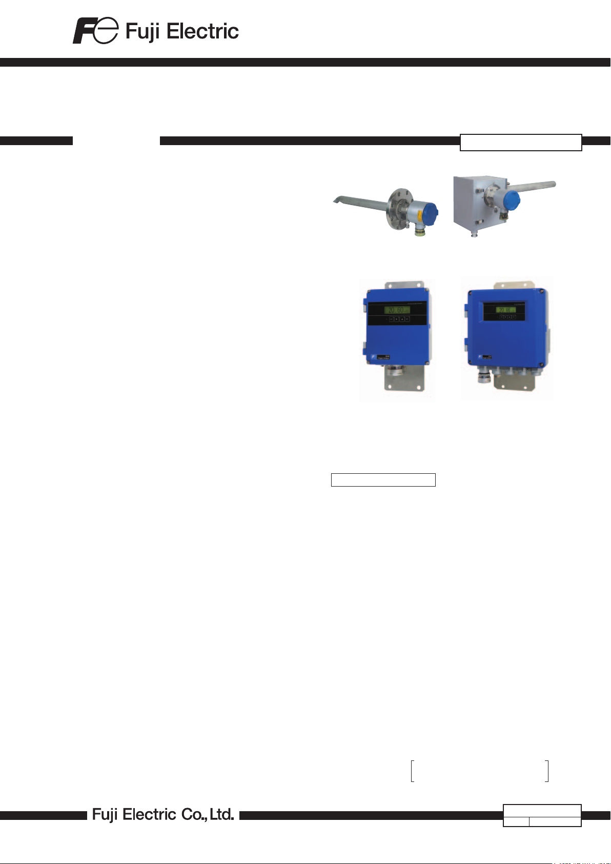
ZFK8, ZKM-2, ZTA
General-use detector
(ZFK8)
<IP66>
Converter (ZKMA)
High-temperature detector
(ZTA)
<IP67>
Converter (ZKMB)
SPECIFICATIONS
General Specifications
Measuring object: Oxygen in noncombustible gas
Measuring method:
Directly insert type zirconia system
Measuring range: 0 to 2 ··· 50 vol% O
(in 1 vol% O2 steps)
Repeatability: Within ±0.5%FS
Linearity: Within ±2%FS
Response time: Within 4 to 7 sec, for 90% (from calibra-
tion gas inlet)
Warmup time: More than 10 min
Analog output: 4 to 20mA DC (allowable load resistance
less than 500W) or 0 to 1V DC (output
resistance more than 100W)
Digital input (option): RS-485 or HART communication
Power supply: Rated voltage;
100 to 120V AC (operating voltage 90
to 132V AC)
200 to 240V AC (operating voltage
190 to 264V AC)
Rated frequency; 50/60Hz
Power consumption:
During warm-up 255VA
During operation 70VA
When the power supply voltage
is 100 or 220 V AC
2
EDSX3-151a
Date
Apr. 25, 2016
Page 2

ZFK8, ZKM-2, ZTA
Detector Specifications (ZFK)
Measured gas temperature:
Flow guide tube system; −10 to +600ºC
(for general-use, corrosive gas)
Ejector system; −10 to +1500ºC (for
high-temperature gas)
−10 to +800ºC (for general-use)
Measured gas pressure:
−3 to +3kPa
Flow guide tube: With or without blow-down nozzle
Flange; JIS5K 65A FF
(JIS5K-80AFF for high particulate gas)
Insertion length; 0.3, 0.5, 0.75, 1m
Ejector (general-use):
Probe for guiding measured gas to
detector
Flange; JIS10K 65A RF
Insertion length; 0.5, 0.75, 1, 1.5m (ac-
cording to customer's specification)
Ejector air inlet flow rate:
5 to 10 L/min
Ejector exhaust gas processing:
Into furnace, returned to flue
Ejector heater temperature drop alarm output:
Alarm output when below 100
ºC Me-
chanical thermostat
N.O. (1a) contact, 200V AC, 2A
Operating temperature:
−10 to +60ºC for Primary detecting ele-
ment
−5 to +100ºC for ejector section
125ºC or less at detector flange surface
with power applied
Storage temperature:
Sensing element: −20 to +70ºC
Ejector: −10 to +100ºC
Structure: Dust/rain-proof structure(IEC IP66
equivalent)
Filter: Alumina(filtering accuracy 50µm) and
quartz paper
Main materials of gas-contacting parts:
Detector; Zirconia, SUS316, platinum
Flow guide tube; SUS304 or SUS316
Ejector (general use); SUS316, SUS304
Ejector; (for high temperature) SiC,
SUS316, SUS304
Calibration gas inlet:
f6mm tube join, f1/4-inch tube join, or
ball valbe (as specified)
Reference air inlet (option):
f6mm tube join or f1/4-inch tube join (as
specified)
Detector mounting:
Horizontal plane ±45º, ambient sur-
rounding air should be clean.
Outer dimensions: (L × max. dia.) 210mm × 100mm (de-
tector)
Mass (approx.) {weight}:
Detector; 1.6kg
Ejector; 15kg (insertion length 1m)
Flow guide tube (general-use, 1m); 5kg
Finish color: Silver and SUS metallic color
Calibration gas flow:
1.5 to 2 L/min
Blowdown air inlet pressure:
2
200 to 300kPa {2 to 3 kgf/cm
}
Converter specification (ZKM)
Concentration value indication:
Digital indication in 4 digits
Contact output signal:
(1) Contact specification; 6 points, 1a 250V AC/3A or 30V DC/3A
(2) Contact function;
• Under maintenance
• Under blowdown
Note3)
• Span calibration gas valve
• Zero calibration gas valve
• Instrument anomalies
• Alarm
• Range identification output
Note2)
Note1)
Note4)
Note1) The following Instrument errors (1) Thermocou-
ples break (2) Sensor break (3) Temperature fault
(4) Calibration fault (5) Zero/span adjustment fault
(6) Output error turn the contact-ON
Note2) Alarm selects just one as mentioned below (1)
High (2) Low (3) Upper and Lower (4) High-high
(5) Low-low, it turns ON while operating.
Note3) Under blow down is available in case of option,
and it turns ON while operating.
Note4) It turns ON during range selection, and turns OFF
when the range 1 is selected.
Contact input signal:
(1) Contact specification; 3points (the following option)
ON; 0V (10mA or less), OFF; 5V
(2) Contact function;
• External hold
• Calculation reset
• Heater OFF
• Blow down (option)
• Inhibition of calibration
• Calibration start
• Range change
Calibration method:
(a) Manual calibration with key operation
(b) Auto. calibration (option)
Calibration cycle; 00 day 00 hour to
99 days 23 hours
(c) All calibration
Calibration gas: • Available range settings
Zero gas; 0.010 to 25.00% O
Span gas: 0.010 to 50.00% O
2
2
• Recommended calibration gas concentration
Zero gas; 0.25 to 2.0% O
Span gas; 20.6 to 21.0% O
2
2
(oxygen concentration in the air)
Blowdown: A function for blowing out with com-
(option)
pressed air dust that has deposited in
the flow guide tube. Blowdown can be
performed for a predetermined time and
at predetermined intervals.
Blowdown cycle; 00 hour 00 minute to
99 hours 59 minutes
Blowdown time; 0 minute 00 second
to 0 minutes 999
seconds
2
Page 3
Output signal hold:
Output signal is held during calibra-
tion, processing diagnosis of sensor,
warm-up, PID auto tuning, under set
up maintenance mode "available" and
blowdown. The hold function can also
be released.
Valve and Flow meter (option):
Selects zero or span gas during manual
zero or span calibration. Mounted on the
side of the converter.
Communication function:
HART communication (option)
RS485 (MODBUS) (option)
Combustion efficiency display (option):
This function calculates and displays
combustion efficiency from oxygen concentration and measured gas temperature.
Thermocouple (R) or thermocouple (K)
is required for temperature measure-
ment.
Range: 0 to 1000°C, Accuracy: ±5°C.
On the version with combustion effi-
ciency display, an alarm function of "rich
mode" indication is also available.
Operating temperature:
−20 to +55ºC
Operating humidity:
95% RH or less, non condensing
Storage temperature:
−30 to +70ºC
Storage humidity: 95% RH or less, non condensing
Enclosure: Dust-proof, rainproof
(corresponding to IP66 or IP67 of IEC)
* when the specified cable gland is at-
tached.
Material: Aluminum case
Outer dimensions (H x W x D):
170 X 159 X 70mm (IP66, Bench type)
220 X 230 X 95mm (IP67)
Mass {weight}: IP66: Approx. 2kg (excluding cable and
detector)
IP67: Approx. 4.5kg (excluding cable and
detector)
Cable:Approx. 4kg/m (with rainproof
flexible conduit)
Finish color: Case: Silver
Cover: Munsell 6PB 3.5/10.5 (blue)
Mounting method: Mounted flush on panel or on pipe
Electrical Safety:
Overvoltage category
; II power supply input
; I relay interfaces
(IEC1010-1)
External overcurrent protective device
; 10A
Equipment interfaces are safety
separated (SELV)
EC Directive Compliance
The product conforms to the requirements of the Low Voltage Directive 2006/95/EC and EMC directive 89/336/EEC
(as amended by Directive 92/31/EEC), both as amended by
Direc-tive 93/68/EEC.
It conforms to following standards for product safety and
electromagnetic compatibility:
EN61010-1 : 2010, EN62311: 2008
Safety requirements for electrical
equipment for measurement, control and
laboratory ese.
“Installation Category II”
“Pollution Degree 2”
“Altitude up to 2187 yard (2,000 m)”
EN61326-1 : 2006, EN61326-2-3: 2006
EN61000-3-2 : 2006, A1: 2009, A2: 2009
EN61000-3-3 : 2008
Electrical equipment for measurment,
control and laboratory use. EMS
requirements.
ZFK, ZKM
3
Page 4
ZFK8, ZKM-2, ZTA
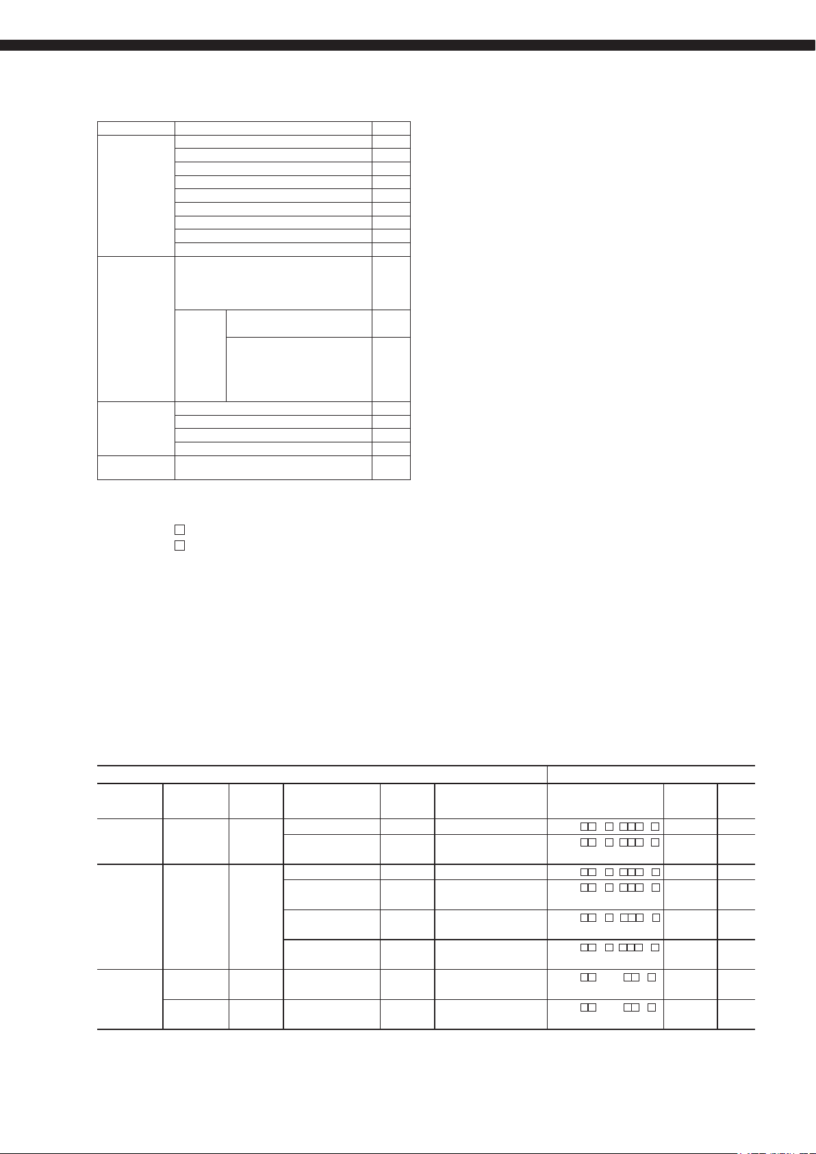
CODE SYMBOLS
(Detector) (Converter)
4 5 6 7 8 9 10 11 12 13 14 15 16
ZFK 8 R 5 - -
Digit Descrip tion Note Code
6 Calibration g as
inlet
7 Power supply 100 to 120 V A C 50/6 0 Hz 1
8 Revision No. 5
9 Flow guide tube
10 fla nge applic ation length
11 no tub e 0Y0
SUS3 04 general use 300 mm 5A3
SUS3 04 general use 500 mm 5A5
SUS3 04 general us e 750 mm 5A7
SUS3 04 general us e 1000 mm 5A1
SUS316 for corros ive gas 300 mm 5B3
SUS316 for corros ive gas 500 mm 5B5
SUS316 for corros ive gas 750 mm 5B7
SUS316 for corros ive gas 1000 mm 5B1
SUS316 with blowd own nozzle 3 00 mm 5C3
SUS317 with blowd own nozzle 5 00 mm 5C5
SUS318 with blowd own nozzle 75 0 mm 5C7
SUS319 with blowd own nozzle 10 00 mm 5C1
SUS316 for high par ticulate 30 0 mm 6D3
SUS317 for high par ticulate 50 0 mm 6D5
SUS318 for high par ticulate 750 mm 6D7
SUS319 for high par ticulate 100 0 mm 6D1
SUS316 for high par ticulate with cover 3 00 mm 6E3
SUS317 for high par ticulate with cover 5 00 mm 6E5
SUS318 for high par ticulate with cover 75 0 mm 6E7
SUS319 for high par ticulate with cover 10 00 mm 6E1
Others ZZZ
12
Heat- retaining
cover
13 Refer ence gas
inlet
14 Filt er spec Standar d 1
15 Inst ruction manual
languag e
16
Specifi cation
namepla te
For ø 6mm tub e (SUS) 1
For ø 1/4 i nch tube (S US) 2
With bal l valve 3
200 to 24 0 V AC 50/6 0 Hz 3
Withou t Y
With A
None Y
For ø 6 mm tube ( SUS) A
For ø 1/4 i nch tube (S US) B
Japanes e J
English E
Chinese C
Standar d (100 to 120 V AC 50 /60 Hz) 1
Standar d (200 to 24 0 V AC 50/6 0 Hz) 2
ZKM 2 - 1 - Y R
Digit Descrip tion Note Code
4 Enclosure IP6 6 A
5 Analog output
signal
6 Communicatio n
functio n
7 Mounting bracket No ne Y
8 Revision No. 2
9 Optional funct ions None Y
10 La nguage Japanes e J
11 Sele ctor valve/
flowmeter
12 — — 1
13 Ca ble gland Withou t Y
14 — — Y
15 — — R
16 Th ermocoupl e
for combus tion
efficie ncy display
*Thermo couple is to be prepare d separately.
Note 2) On the version with combustion efficiency display, an alarm function of "rich mode" indication is
4 5 6 7 8 9 10 11 12 13 14 15 16
IP67 B
4 to 20 mA DC B
0 to 1 V DC E
None Y
RS- 485 2
HART 3
Mounting o n panel surface 1
Pipe moun ting 2
Combus tion efficie ncy display Note 2 1
Blowdown 2
Auto calib ration 3
Combus tion efficie ncy display + Bl owdown Note 2 4
Combus tion efficie ncy display + Au to calibration Note 2 5
Blowdown + A uto calibration 6
Combus tion efficie ncy display + Bl owdown + Auto
calibra tion
English E
Chinese C
None Y
With val ve (For ø6 mm t ube) 1
With val ve + flowmeter ( For ø6 mm tube ) 2
With val ve (For ø1/ 4 inch tube) 3
With val ve + flowmeter ( For ø1/4 inch t ube) 4
With A
None Y
Type R thermo couple R
Type K thermo couple K
also available.
Note 2 7
4 5 6 7 8
ZTA 1 1
Digit Descrip tion Note Code
4 Measured gas
temperatu re
5 — — 1
6 Insertion len gth
[mm]
7 Power supply
voltage
8 Revision No. — 1
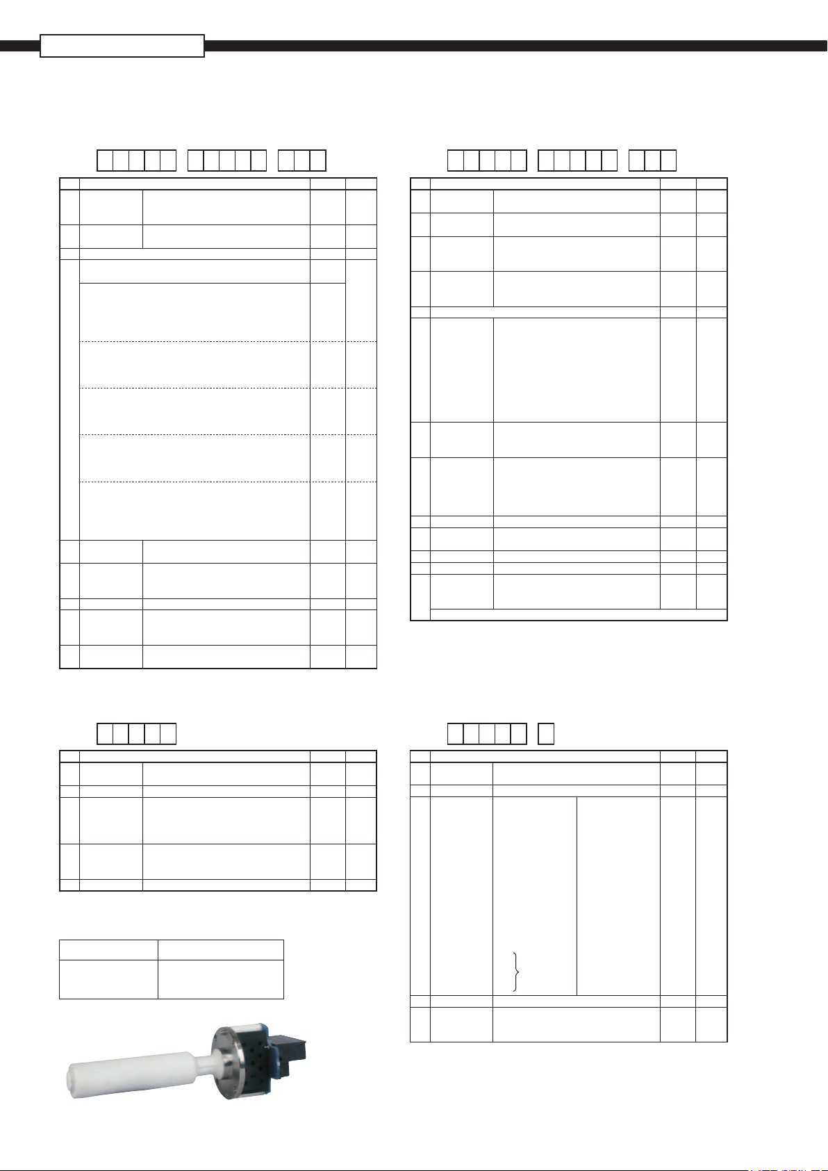
(Replacement Detector element)
Power supply Code symbols
100 to 120V AC ZFK8YY15-0Y0YY-0YY
200 to 240V AC ZFK8YY35-0Y0YY-0YY
For high tem perature (+150 0°C max.) 1
General u se (+80 0°C max.) 2
500 B
750 C
1000 D
1500 E
100V/ 115 V AC 50 /60 Hz 1
200V /220 V AC 50 /60Hz 3
230 V AC 5 0/60 Hz 5
(Dedicated cable)(Ejector)
4 5 6 7 8 9
ZRZ K R 1 -
Digit Descrip tion Note Code
Connec table
4
device
5 Type R t hermocoup le R
6 Length
7 N one 6 m YA
8 Revision No. — 1
9 Cable end
treatment
Note 1) F or connection between detector and converter, use a rainproof flexible conduit.
ZKM K
Rainproof fl exible conduit
None 10 m YB
None 15 m YC
None 20 m YD
None 30 m YE
None 40 m YF
None 50 m YG
None 60 m YH
None 70 m YJ
None 80 m YK
None 90 m YL
None 100 m YM
6 m 6 m Note 1 AA
10 m 10 m Note 1 BB
Note 1
15 m 15 m Note 1 CC
20 m 25 m Note 1 DD
None 0
One side ( detector side) 1
Both sides 2
Cable
4
Page 5
SCOPE OF DELIVERY
Detector ( ZFK) Detector main unit 1
Converter (ZKM ) Converter main unit 1
Ejector ( ZTA) Ejector main unit 1
Dedicated cable
(ZRZ)
Viton O ring 1
Mounting screw (M5 x 16 ) 6
Thermal sticker 1
Ceramic filter 1
Instruction manual 1
Flow guide tube (as specified ) 1
Heat-retaining cover (as specified) 1
Reference gas inlet port ( as specified) 2
Fuse (2.5A) 2
Ferrite core 1
Instruction manual 1
Metal
fittings
Insertion tube 1
Packing 1
M16 nut and washer ( stainless steel) 4
Cable ( of the specified length) 1
Items to be prepared separately:
(1) Standard gas for calibration
Type ZBM
Type ZBM
NSH4-01 (up to 5% O2 range)
NSJ4-01 (over 5% O2 range)
(2) Pressure regulator for standard gas (type ZBD61003)
(3) Flowmeter
Type; ZBD42203, 0.2 to 2L/min (for calibrating gas)
Type; ZBD42403, 1 to 10L/min (for ejector)
Description Q'ty
<For panel mounting >
M8 sems screw (stainless steel) 4
<For pipe mounting >
U bolt (stainless steel) 2
M8 nut and washer (stainless
steel)
Suppor t (stainless steel) 2
CAUTIONS
• If combustible gas (CO, H2 etc.) exists in the measured
gas, error will occur due to burning at the sensor section.
The inclusion of corrosive gas (Si vapor, alkaline metal, P,
Pb etc.) will shorten the life of the sensor.
• When the measured gas temperature is high (+300°C
or higher), the flange should be separated from the
furnace wall in order to bring the detector flange surface
temperature below the specified value +125°C). The flow
guide should be attached in the direction in which the gas
flow to the detector decreases.
• When much dust is included in the gas, the flow guide
tube should be attached at an inclination so that the flow
goes from below to above. And the flow guide tube
should be attached in the direction in which the gas flow
to the detector decreases.
• In the case of a refuse incinerator, automatic blow down
4
of the flow guide should not be performed (to prevent
corrosion of the flow guide tube due to drainage). Blowdown should be performed manually when change in
the indication has become very little with the furnace
stopped.
DEVICE CONFIGURATION
The device to be combined differ according to the conditions of the gas to be measured. Select the devices to be combined
with reference to the following table.
Measured gas Device configuration
Application Temperature Gas Flow DUST Heat-
General-use
(boiler)
For corrosive
gas (refuse
incinerator)
General-use
(boiler)
Note (1) Dust volume is approximate value.
(2) Instrument quality air or bottled air is available as reference air by selecting detector with reference air inlet.
600ºC or
less
600ºC or
less
800ºC or
less
1500ºC or
less
5 to 20m/s Less than 0.2g/Nm
Less than 10g/Nm
5 to 20m/s Less than 1g/Nm
Less than 10g/Nm
Less than 25g/Nm
Less than 25g/Nm
Less than
1m/s
Less than
1m/s
Less than 1g/Nm
Less than 1g/Nm
retaining
cover
3
—
3
—
3
—
3
—
3
no
3
yes
3
—
3
— SIC tube
Note Detector type Converter
Fuel; gas, oil
Fuel: coal
with blow down
Included low moisture
Included low moisture
with blow down
Included low moisture
with blow down
Included high moisture
with blow down
SUS316 tube
with blow down
ZFK8R
ZFK8R
ZFK8R
ZFK8R
ZFK8R
ZFK8R
ZFK8R
ZFK8R 5-0Y0 -1
with blow down
5
5- A -1
5
5- C -1
5
5- B -2
5
5- C -2
6
5- D -2
6
5- E -2
5- 0Y0 -1
type
ZKM —
ZKM —
ZKM —
ZKM —
ZKM —
ZKM —
ZKM ZTA2
ZKM ZTA1
Ejector
type
5
Page 6
ZFK8, ZKM-2, ZTA
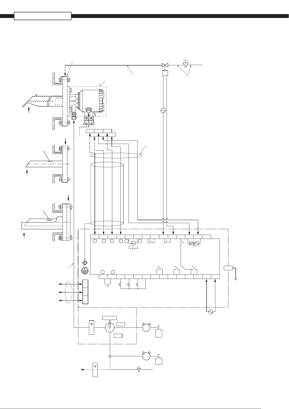
Flow guide tube system (with valve)
CONFIGURATION
Rc1/4
(upper side blow port should be selected)
Blow-down, 200 to 300kPa
Flow guide tube
Gas temperature.
600ºC max.
*2
Ref. air
Sample gas outlet
Gas temperature.
600ºC max.
Flow guide tube
for high particulate
Blue
Heat-retaining cover
123
6
Red
Yellow
Detector
(ZFK8)
45
White
Black
White
15ASGP
tube equivalent
or ø10/ø8 PTFE
pipe or copper pipe
(not supplied)
AC power
supply
Rainproof flexible
conduit.
(Max. 20m)
Solenoid valve
(not supplied)
Pressure regulator
(unnecessary when supply air pressure is
200 to 300kPa)
Supply air
15ASGP
tube equivalent
or ø10/ø8 PTFE
pipe or copper pipe
(not supplied)
Sample gas outlet
Gas temperature.
600ºC max.
Flow guide tube for high
particulate with cover
ø6mm or ø1/4 inch tube
for calibration gas
(not supplied)
RS485
(option)
(Option)
*2 Ref. air
to Detector
1152 3 4 5 6 7 8 9 10 11 1 2 13 14
−
O2
Thermocouple
for combustion
control
+
TC2
+
TC1
Thermocouple
input
−
+
O2 input
*4
16
+
−
Analog output
4 to 20mA DC
or 0 to 1V DC
Contact input
DI1
17
AO
or
DI2 DI3
18 19
−
FAULT BLOW
Fault
contact
output
ALAR M MA INTE
DICO M
20
Alarm
contact
output
21 22
Blow
contact
output
Maintenance
contact
output
23 24
ZV
GAS
Calibrating
gas contact
output
ZERO
1 2 3
TM-2
Flowmeter
Valve
MEASURE
Pressure regulator
(ZBD6)
ZERO
Standard gas
for zero point (ZBM)
*1
Span gas (ZBM)
Flowmeter
SPAN
Pressure regulator
(ZBD6)
*1 Air supply
Pressure regulator
(0.2 to 0.5L/min)
(not supplied)
(unnecessary when
supply air pressure
is 50 to 100kPa)
Converter (ZKM)
TM-1
HEATER
Calibrating gas
contact output
COM
25 28
Note:
AC power
SPAN
supply
GAS
AC
LSV
26 27
*1 Standard gas or instrumentation air
can be used in place of span gas.
*2 Instrument quality air or bottled air is
available as reference air instead of
ambient air.
*3 Protective earth.
*4 Connect the shield of a exclusive cable
with the ground terminal in the converter.
*5 HART communication (option) uses a
4-20mA analog output terminal.
PE
N
*3
6
Page 7

Flow guide tube system
Rc1/4
(upper side blow port should be selected)
Blow-down, 200 to 300kPa
Solenoid valve
(not supplied)
Pressure regulator
(unnecessary when supply air pressure is
200 to 300kPa)
Supply air
Flow guide tube
Gas temperature.
600ºC max.
Sample gas outlet
Gas temperature.
600ºC max.
Flow guide tube
for high particulate
Sample gas outlet
*2
Ref. air
Heat-retaining cover
6
Blue
Yellow
123
Detector
(ZFK8)
45
Red
White
Black
White
15ASGP
tube equivalent
or ø10/ø8 PTFE
pipe or copper pipe
(not supplied)
AC power
supply
Rainproof flexible
conduit.
(Max. 20m)
15ASGP
tube equivalent
or ø10/ø8 PTFE
pipe or copper pipe
(not supplied)
Gas temperature.
600ºC max.
Flow guide tube for high
particulate with cover
+
O2
O2 input
*4
1152 3 4 5 6 7 8 9 10 11 1 2 13 14
ø6mm or ø1/4 inch tube
for calibration gas
(not supplied)
1 2 3
RS485
(option)
TM-2
Flowmeter
(ZBD4)
(1 to 1.5L/min)
*2 Ref. air
to Detector
(0.2 to 0.5L/min)
(not supplied)
*1 Standard gas or instrumentation air can be used in place of span gas.
Note:
*2 Instrument quality air or bottled air is available as reference air instead
of ambient air.
*3 Protective earth.
*4 Connect the shield of a exclusive cable with the ground terminal in
the converter.
*5 HART communication (option) uses a 4-20mA analog output terminal.
+
−
Thermocouple
Thermocouple
for combustion
control
+
−
TC2
16
TC1
input
+
−
4 to 20mA DC
Contact input
DI1
17
Joint
AO
or
Analog output
or 0 to 1V DC
DI2 DI3
18 19
Solenoid valve
(not supplied)
Solenoid valve
(not supplied)
−
FAULT BLOW
Fault
contact
output
ALAR M MAIN TE
DICO M
20
Blow
contact
output
Alarm
Maintenance
contact
contact
output
output
21 22
Pressure regulator
(ZBD6)
23 24
Pressure regulator
(unnecessary when supply air pressure is 50 to 100kPa)
Pressure regulator
(ZBD6)
ZV
ZERO
GAS
Calibrating
gas contact
output
Calibrating gas
contact output
COM
25 28
Standard gas
for zero point (ZBM)
*1
Standard gas for
span point (ZBM)
HEATER
SPAN
GAS
26 27
Span point
Converter (ZKM)
AC power
supply
AC
N
LSV
AC power
supply
*1 Air supply
TM-1
*3
PE
7
Page 8

ZFK8, ZKM-2, ZTA
Ejector system (with valve)
Gas temperature.
1500ºC max.
Bule
Ejector (ZTA)
Detector (ZFK8)
123
6
Black
Yellow
Red
Flowmeter
Ejector (5 to 10L/min)
Power supply
1
2
Heater temperature drop
4
5
Alarm
Copper pipe
ø10/ø8mm
(not supplied)
45
White
White
(ZBD)
Copper pipe ø6/ø4mm
(not supplied)
Solenoid valve
(not supplied)
AC power
supply
Rainproof flexible
conduit.
(Max. 20m)
Pressure regulator
(unnecessary when supply air pressure
is 200 to 300kPa )
Joint
Copper pipe ø10/ø8mm
(not supplied)
Supply air
ø6mm or ø1/4 inch tube
for calibration gas
(not supplied)
RS485
(option)
(Option)
*2 Ref. air
to Detector
1152 3 4 5 6 7 8 9 10 11 1 2 13 14
−
O2
Thermocouple
for combustion
control
+
TC2
+
TC1
Thermocouple
input
−
+
O2 input
*4
16
+
−
Analog output
4 to 20mA DC
or 0 to 1V DC
Contact input
DI1
17
AO
or
DI2 DI3
18 19
−
FAULT BLOW
Fault
contact
output
ALAR M MA INTE
DICO M
20
Alarm
contact
output
21 22
Blow
contact
output
Maintenance
contact
output
23 24
ZV
ZERO
GAS
Calibrating
gas contact
output
Calibrating gas
contact output
COM
1 2 3
TM-2
Flowmeter
Valve
MEASURE
Pressure regulator
(ZBD6)
ZERO
Standard gas
for zero point (ZBM)
*1
Span gas (ZBM)
Flowmeter
SPAN
Pressure regulator
(ZBD6)
*1 Air supply
Pressure regulator
(0.2 to 0.5L/min)
(not supplied)
(unnecessary when
supply air pressure
is 50 to 100kPa)
*1 Standard gas or instrumentation air
Note:
can be used in place of span gas.
*2 Instrument quality air or bottled air is
available as reference air instead of
ambient air.
*3 Protective earth.
*4 Connect the shield of a exclusive cable
with the ground terminal in the converter.
*5 HART communication (option) uses a
4-20mA analog output terminal.
HEATER
Heater
AC power
SPAN
supply
GAS
AC
LSV
26 27
25 28
TM-1
N
AC power
supply
*3
PE
8
Page 9

Ejector system
Gas temperature.
1500ºC max.
Ejector (ZTA)
Detector (ZFK8)
6
Bule
123
Yellow
Black
Red
Flowmeter
Ejector (5 to 10L/min)
Power supply
1
2
Heater temperature drop
4
5
Alarm
Copper pipe
ø10/ø8mm
(not supplied)
45
White
White
(ZBD)
Copper pipe ø6/ø4mm
(not supplied)
Solenoid valve
(not supplied)
AC power
supply
Rainproof flexible
conduit.
(Max. 20m)
Pressure regulator
(unnecessary when supply air pressure
is 200 to 300kPa )
Joint
Copper pipe ø10/ø8mm
(not supplied)
Supply air
1152 3 4 5 6 7 8 9 10 11 1 2 13 14
+
−
O2
O2 input
*4
Thermocouple
for combustion
ø6mm or ø1/4 inch tube
for calibration gas
(not supplied)
control
+
TC2
1 2 3
RS485
(option)
TM-2
(1 to 1.5L/min)
Flowmeter
(ZBD4)
*2 Ref. air
to Detector
(0.2 to 0.5L/min)
(not supplied)
*1 Standard gas or instrumentation air can be used in place of span gas.
Note:
*2 Instrument quality air or bottled air is available as reference air instead
of ambient air.
*3 Protective earth.
*4 Connect the shield of a exclusive cable with the ground terminal in
the converter.
*5 HART communication (option) uses a 4-20mA analog output terminal.
+
−
TC1
Thermocouple
input
−
DI1
16
17
Joint
AO
+
or
Analog output
4 to 20mA DC
or 0 to 1V DC
Contact input
DI2 DI3
18 19
Solenoid valve
(not supplied)
Solenoid valve
(not supplied)
−
FAULT BLOW
Fault
contact
output
ALAR M MA INTE
DICO M
20
Blow
gas contact
contact
output
Alarm
Maintenance
contact
21 22
Pressure regulator
(ZBD6)
contact
output
output
23 24
Pressure regulator (unnecessary when
supply air pressure is 50 to 100kPa)
Pressure regulator
(ZBD6)
ZV
ZERO
GAS
Calibrating
output
Standard gas
for zero point (ZBM)
HEATER
Calibrating gas
contact output
COM
25 28
Span gas
*1 Standard gas for
span point (ZBM)
SPAN
GAS
26 27
*1 Air supply
AC power
supply
AC
LSV
TM-1
N
AC power
supply
*3
PE
9
Page 10

ZFK8, ZKM-2, ZTA
OUTLINE DIAGRAM
ø80
ø67
6-ø6
60°
ø80
ø67
6-ø6
(Unit:mm)
ø26
Ref. Air inlet (to order)
SUS316,for ø6/ø4 tube
or 1/4 inch tube
Approx.62
Filter
Approx.62
Detector (ZFK8)
Heat-retaining cover
5
(To order )
Approx.30
Calibration gas inlet
(To order)
SUS316,for ø6/ø4 tube
or 1/4 inch tube
Heat-retaining cover
5
(to order)
Approx.132
Approx.130
Approx.132
Approx.130
Terminal box
Ground-wire
Screw: M4
Dedicated
Cable gland
Terminal box
EXTERNAL CONNECTION DIAGRAM
ø79
Heater Thermocouple
ø85
125.5
1
Black / White/ red / White/ yellow / blue
2-core wire 4-core wire
3
2
Dedicated cable
Element output
4 5 6
60°
ø26
ZFK8R 3
Ball valve
Ref. air inlet (to order)
SUS316,for ø6/ø4 tube
or 1/4 inch tube
Calibration gas inlet
Rc1/4 INT.THD.
Filter
Approx.100
Valve handle
ø79
125.5
Ground-wire
screw: M4
Dedicated cable gland
ø85
10
Page 11

Sensor unit (ZFK8YY)
(132.7)
(88.4) 3.5
(?17.5)
20
4-φ3.5(Mount for detector)
TK4J4664R0
45°
45°
T+
φ
35
40
S+
6
madeinjapan
5
S-
H
1
3
4
2
H
T-
Flow guide tube
12
Approx. L
Approx. 20
Gas inlet
34
155
130
67
Oxygen detector
Z F K 8 R 5 - 5 A 3
3
2.7
0.3
5 7
0.5
3.3
0.75
4.1
Code 11th
L (m)
MASS
Approx.(kg)
5
7
1
1
1.0
4.8
Z
L=
(to order)
Gas outlet
20
6-M5
detector side
8–15
MTG. holes
Flow guide tube (with blow-down nozzle)
18
Approx. L
Approx. 20
3
60.5
67
Gas inlet
6-M5
detector side
155
130
67
Z F K 8 R 5 - 5 C 3
5
7
1
Oxygen detector
Gas outlet
Blow down air inlet
4-Rc1/4
with plug int.thd.
8–15
MTG. holes
Code 11th
L (m)
Mass
Approx.(kg)
3
0.3
3.0
5 7
0.5 0.75 1.0
3.8
4.8
1
5.7
Z
L=
(to order)
11
Page 12

ZFK8, ZKM-2, ZTA
4 - Rc 1/4
with plug int thd.
6 - M5 Screw
for mounting
to detector
Flange: JIS 5K80A FF
ZFK MTG. position
Packing
Gas flow
Flow guide tube (for high particulate)
180
145
Blow down air inlet
Select an upper port to
avoid the condensation
in the piping
29.5
Gas outlet
Tube (50A SCH40)
800
67
8 - 19
MTG. hole
185
Z F K 8 R 5 - 6 D
50
30
Code 11th
L (m)
Mass
Approx.(kg)
3
0.3
4.5
3
5
7
1
5 7
0.5 0.75 1.0
5.6
8.3
7.0
1
Z
L=
(to order)
4 - Rc 1/4
with plug int thd.
6 - M5 Screw
for mounting
to detector
Flange: JIS 5K80A FF
ZFK MTG. position
Packing
Gas flow
Flow guide tube (for high particulate with cover)
180
145
Blow down air inlet
Select an upper port to
avoid the condensation
in the piping
(175)
50
30
Gas outlet
(790)
67
29.5
800
8 - 19
MTG. holes
Z F K 8 R 5 - 6 E
3
Code 11th
L (m)
Mass
Approx.(kg)
0.3
7.1
5 7
0.5 0.75 1.0
9.0
11.4
3
5
7
1
1
Z
L=
(to order)
13.6
12
Protection tube (65A SCH40)
(38)
Tube (50A SCH40)
Page 13

Flow guide tube (
12
Approx. L
3
Gas inlet
67
60.5
Approx. 40
for corrosive gas)
155
130
67
Oxygen detector
Viewed from P direction
105
140
(JIS 10K65ARF)
8
Gas inlet
25
Ejector air
outlet
(Rc1/4)
Gas outlet
6-M5
detector side
Ejector (ZTA)
42.7
4-M16 bolt
P
L [mm]
500 750 1000 1500
Approx. L
30
EXTERNAL CONNECTION DAIAGRAM
1 2 3 4 5
AC
power supply
AC100/110V
AC200/220V
AC230V
Power consumption: 150 W
Heater temp.drop alarm
Z F K 8 R 5 - 5 B 3
3
Code 11th
L (m)
MASS
Approx.(kg)
8- 15
MTG. holes
190
217
40
35
Blow -down air inlet
(Rc1/4)
Ejector air inlet
(Rc1/4)
40
0.5
0.3
3.3
170
50
45
Cable gland
(A15C)
5 7
4.5
0.75
6.1
5
7
1
1
1.0
7.6
Detector
(ZFK8)
Z
L=
(to order)
13
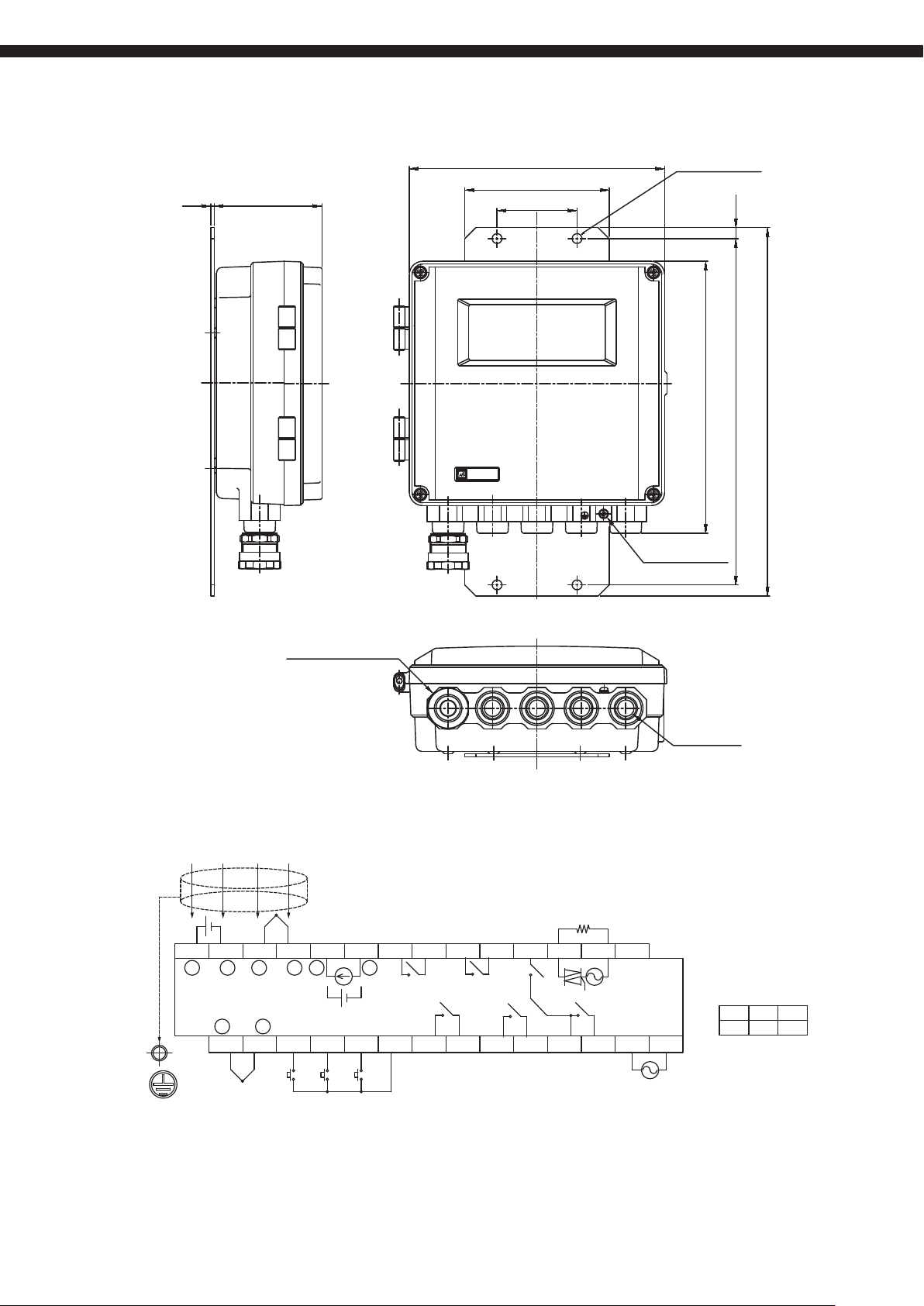
Page 14

ZFK8, ZKM-2, ZTA
Converter (ZKMA)
<IP66 enclosure>
2.5
77
2-ø21.2, 3-mm depth
For cable gland
Earth terminal (M4)
Waterproof connector for
connection to detector
ZKM
Oxygen Analyzer
142
100
72
Zirconia Oxygen Analyzer
ENTESC
Mounting hole 4-ø9
10
170
250
2-ø17, 3-mm depth
For cable gland
270
*2
Exclusive
cable
Ground
terminal
M4
sensor
O
O2 sensor
input
2
thermocouple
input
1152 3 4 5 6 7 8 9 10 11 12 13 14
−
2
+
TC2
Thermocouple
input type R
(not supplied)
+ +
TC1
DI1
−
16
17
Contact input
Short circuit : on (Current 5mA)
Open : off (Voltage 5V)
+
O
EXTERNAL TERMINAL (TM1) / Terminal M3
Analog
output
4-20mA DC
or 0-1V DC
AO
− −
or
DI2 DI3
18 19
Fault
contact output
250V AC/3A
30V DC/3A
FAULT
ALARM MAINTE
DICOM
21 22
20
Alarm
contact output
250V AC/3A
30V DC/3A
Blow contact
output
250V AC/3A
30V DC/3A
BLOW
ZV
23 24
Maintenance
contact output
250V AC/3A
30V DC/3A
*1
sensor
O
2
heater power
output
ZERO
GAS
HEATER
SPAN
GAS
26 27
25 28
Calibrating gas
contact output
250V AC/3A
30V DC/3A
Note 1) The heater power supply is the same as the converter power supply.
Note 2) Be sure to connect the shield of the cable to the ground in the main body.
Note 3) HART communication (option) uses a 4-20 mA analog output.
AC
N
LSVCOM
AC
Power supply
input
100 to120V AC
200 to 240V AC
RS485 communication
(option) terminal
1
2 3
GND TRX+ TRX-
14
Page 15
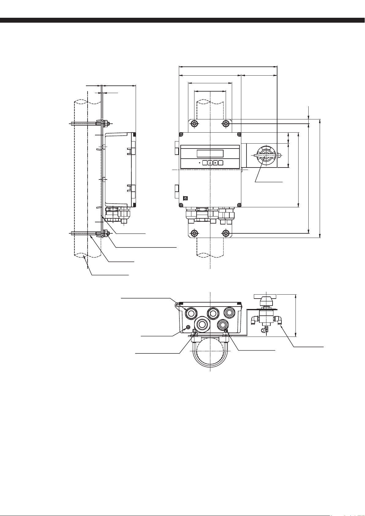
Converter (ZKMA)
<IP66 enclosure> with selector valve
77.12.5
2.5
ZKM
Oxygen Analyzer
224
142 82
100
72
Zirconia Oxygen Analyzer
ENTESC
A
E
S
.
M
N
O
Z
S
Valve (option)
10
2555
170
250
270
Support (option)
Spring washer, washer, nut (option)
U bolt (option)
(50A pipe or 2B pipe)
Cable gland (option)
for ø6-ø12 mm tube
Earth terminal (M4)
Waterproof connector for
connection to detector
Cable gland (option)
for ø5-ø10 mm tube
96.5
For ø6 mm tube
or ø1/4 inch tube
15
Page 16

ZFK8, ZKM-2, ZTA
Converter (ZKMA)
<IP66 enclosure> with selector valve and owmeter
77.12.5
2.5
ZKM
Oxygen Analyzer
224
142 82
100
72
Valve
(option)
Zirconia Oxygen Analyzer
ENTESC
A
E
S
.
M
N
O
Z
S
170
250 10
270
Support (option)
Spring washer, washer, nut (option)
U bolt (option)
(50A pipe or 2B pipe)
Cable gland (option)
for ø6-ø12 mm tube
Earth terminal (M4)
Waterproof connector for
connection to detector
Cable gland (option)
for φ5-φ10 mm tube
Flowmeter (option)
116
For ø6 mm tube
or ø1/4 inch tube
16
Page 17
Converter (ZKMB)
<IP67 enclosure>
230
130
973
ZKM
Oxygen Analyzer
72
Mounting hole 4-ø9
245
Earth terminal (M4)
10
312
332
*2
Exclusive
cable
Ground
terminal
M4
Waterproof connector for
connection to detector
sensor
O
O2 sensor
input
2
thermocouple
input
1152 3 4 5 6 7 8 9 10 11 12 13 14
−
2
+
TC2
Thermocouple
input type R
(not supplied)
+ +
TC1
DI1
−
16
17
Contact input
Short circuit : on (Current 5mA)
Open : off (Voltage 5V)
+
O
EXTERNAL TERMINAL (TM1) / Terminal M3
Analog
output
4-20mA DC
or 0-1V DC
AO
− −
or
DI2 DI3
18 19
Fault
contact output
250V AC/3A
30V DC/3A
FAULT
ALARM MAINTE
DICOM
21 22
20
Alarm
contact output
250V AC/3A
30V DC/3A
Blow contact
output
250V AC/3A
30V DC/3A
BLOW
ZV
ZERO
23 24
Maintenance
contact output
250V AC/3A
30V DC/3A
*1
sensor
O
2
heater power
output
GAS
HEATER
SPAN
GAS
26 27
25 28
Calibrating gas
contact output
250V AC/3A
30V DC/3A
100 to120V AC
200 to 240V AC
AC
N
LSVCOM
AC
Power supply
input
4-G1/2
for cable gland
RS485 communication
(option) terminal
1
GND TRX+ TRX-
2 3
Note 1) The heater power supply is the same as the converter power supply.
Note 2) Be sure to connect the shield of the cable to the ground in the main body.
Note 3) HART communication (option) uses a 4-20 mA analog output.
17
Page 18

ZFK8, ZKM-2, ZTA
230 80
Converter (ZKMB)
<IP67 enclosure> with selector valve
973
2.5
130
72
10
A
E
S
.
M
N
O
Z
55 58.5
S
Support (option)
Spring washer, washer, nut (option)
U bolt (option)
(50A pipe or 2B pipe)
Waterproof connector for
connection to detector
ZKM
Oxygen Analyzer
Valve
(option)
Earth terminal (M4)
284
97
312
332
18
For ø6 mm tube
or ø1/4 inch tube
Cable gland (option) × 4
for ø6-ø12 mm tube
Page 19

Converter (ZKMB)
<IP67 enclosure> with selector valve and owmeter
2.5
973
ZKM
Oxygen Analyzer
230 80
130
72
Valve
(option)
10
58.5
A
E
S
.
M
N
O
Z
S
332
312
284
Support (option)
Spring washer, washer, nut (option)
U bolt (option)
(50A pipe or 2B pipe)
Waterproof connector for
connection to detector
Earth terminal (M4)
Cable gland (option) × 4
for ø6-ø12 mm tube
Flowmeter (option)
117
For ø6 mm tube
or ø1/4 inch tube
19
Page 20

Caution on Safety
ZFK8, ZKM-2, ZTA
*Before using this product, be sure to read its instruction manual in advance.
Grobal Sales Section
Instrumentation & Sensors Planning Dept.
1, Fuji-machi, Hino-city, Tokyo 191-8502, Japan
http://www.fujielectric.com
Phone: +81-42-514-8930 Fax: +81-42-583-8275
http://www.fujielectric.com/products/instruments/
Information in this catalog is subject to change without notice.
Print ed in J apan
 Loading...