

Page 1
IN-SITU
ZIRCONIA OXYGEN ANALYZER
FOR HAZARDOUS LOCATION
DATA SHEET
This oxygen analyzer is used to continuously measure
oxygen concentration in noncombustible exhaust gas of
industrial boilers or furnaces, and is ideally suited for combustion management and control.
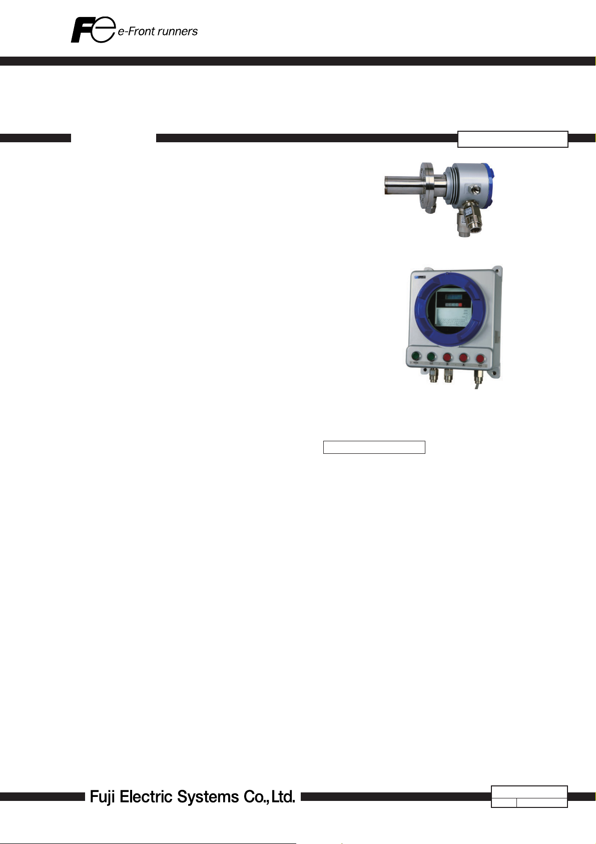
The analyzer system is comprised of the detector and
converter coupled together as a complete system. Detector setting configuration includes the flow guide tube and
detector sensor. The flow guide tube is inserted directly
into the gas and directs gas to the sensor for measurement.
The converter (ZKME) is comprised of the signal processor, input/output and communications, display and system
controls.
The converter is equipped with advanced functionality such as performing the sensor diagnostics and sensor
recovery function, so the detector can be used within long
term stability.
ZFKE, ZKME
Detector (ZFKE)
FEATURES
1. Gas sampling device is unnecessary
For quick response, insert the detector directly into the
staek. Gas sampling functions such as a gas aspirator
and a dehumidifier are not required.
2. Easy maintenance
The sensor equipped with the detector, has unit construc-
tion, it is easy to replace.
By separating the detector and the flow guide tube, filter
replacement is easy.
3. More reliable than sensor diagnosis, sensor recoverable
function
Depending on the components in the measurement
gas, the characteristics of the sensor might deteriorate.
The equipment includes sensor recovery function electronically, checking the deterioration status of the sensor
depletion.
Therefore, it has high reliability and long-lasting stability.
4. Safe and secure
System detects thermocouple break for heater control on
the sensor side. Safety functions of isolating power supply to the detector or isoralting power via external contact
input are also.
5. Easy operation
The operation and setting for the converter can be per-
formed interactively, and available as English, Japanese
or Chinese for language display.
Converter (ZKME)
SPECIFICATIONS
General Specifications
Measuring object: Oxygen in noncombustible gas
Measuring method:
Directly insert type zirconia system
Measuring range: 0 to 2 ··· 0 to 50 vol% O
2 ranges available in 1 vol% O2 steps
Repeatability: Within ±0.5%FS
Linearity: Within ±2%FS
Response time: Within 4 to 7 sec, for 90% (from calibra-
tion gas inlet)
Warmup time: approx. 10 min
Analog output: 4 to 20mA DC (allowable load resis-
tance less than 500Ω) or 0 to 1V DC
(output resistance more than 100Ω)
Power supply: Rated voltage;
100 to 120V AC (operating voltage 90
to 132V AC)
200 to 240V AC (operating voltage
190 to 264V AC)
Rated frequency; 50/60Hz
Power consumption:
Maximum 240VA (Detector: approx.
200VA, Converter: approx. 40VA)
Normal 70VA (Detector: approx. 50VA,
Converter: approx. 20VA
2
EDS3-139a
Date
May. 8, 2009
Page 2

ZFKE, ZKME
Detector Specifications (ZFKE)
Measured gas temperature:
Flow guide tube system; −10 to +600ºC
(for general-use, corrosive gas)
Measured gas pressure:
−3 to +3kPa (−306 to +306mmH
O)
2
Flow guide tube: With or without blow-down nozzle
Flange; JIS5K 65A FF
(JIS5K-80AFF for high particulate gas)
Insertion length; 0.3, 0.5, 0.75, 1m
Other: See. Code Symbols
Ejector (general-use):
Probe for vacumming up measured gas
to detector (option)
Operating temperature:
−10 to +60ºC for Primary detecting ele-
ment
125ºC or less at detector flange surface
with power applied
Storage temperature:
Sensing element: −20 to +70ºC
Structure: Dust/rain-proof structure(IEC IP66
equivalent)
Flame proof: See Table 1.
Filter: SUS316 (filtering accuracy 60μm)
Main materials of gas-contacting parts:
Detector; Zirconia, SUS316, platinum
Flow guide tube; SUS316
Calibration gas inlet:
φ6mm tube join or φ1/4-inch tube join (as
specified)
Reference gas inlet (option):
φ6mm tube join or φ1/4-inch tube join (as
specified)
Detector mounting:
Horizontal plane ±45º, ambient sur-
rounding air should be clean.
Outer dimensions: (L × max. dia.) 215mm × 164mm (de-
tector)
Mass (approx.) {weight}:
Detector; 3.0kg
Flow guide tube (for corrosive gas, 1m);
6kg
Finish color: Case: Silver and SUS metallic color
Cover: Blue
Ejector air inlet flow rate:
5 to 10 L/min
Calibration gas flow:
1.5 to 2 L/min
Blowdown air inlet pressure:
2
200 to 300kPa {2 to 3 kgf/cm
1
Table
Detector
TIIS
pending
(
NEPSI EExd IIC T5 Ex II2G
)
Exd IIB T4
}
Converter specification (ZKME)
Concentration value indication:
Digital indication in 4 digits
Contact output signal:
(1) Contact specification; 6 points, 1a 250V AC/3A or 30V
DC/3A
(2) Contact function;
• Under maintenance
• Under blowdown Note3)
• Span calibrating gas
• Zero calibration gas
• Instrument anomalies Note1)
• Alarm Note2)
Note1) The following Instrument errors (1) Thermocou-
ples break (2) Sensor break (3) Temperature fault
(4) Calibration fault (5) Zero/span adjustment fault
(6) Output error turn the contact-ON
Note2) Alarm selects just one as mentioned below (1)
High (2) Low (3) Upper and Lower (4) High-high
(5) Low-low, it turns ON while operating.
Note3) Under blow down is available in case of option,
and it turns ON while operating.
Contact input signal:
(1) Contact specification; 3points (the following option)
ON; 0V (10mA or less), OFF; 5V
(2) Contact function;
• External hold
• Calculation reset
• Heater OFF
• Blow down (option)
• Inhibition of calibration
• Calibration start
• Range change
Calibration method:
(a) Manual calibration with key opera-
tion
(b) Auto. calibration (option)
Calibration cycle; 00 day 00 hour to
99 days 23 hours
(c) All calibration
Calibration gas: • Range settings
Zero gas; 0.010 to 25.00% O
Span gas: 0.010 to 50.00% O
2
2
• Recommended calibration gas concen-
tration
Zero gas; 0.25 to 2.0% O
Span gas; 20.6 to 21.0% O
2
2
(oxygen concentration in the
air)
Blowdown: A function for blowing out with com-
pressed air dust that has deposited in
(option)
the flow guide tube. Blowdown can
be performed for a predetermined time
and at predetermined intervals.
Blowdown cycle; 00 hour 00 minute to
99 hours 59 minutes
Blowdown time; 0 minute 00 second
to 0 minutes 999
seconds
2
Page 3

Output signal hold:
Output signal is held during cali-
bration, processing recoverable
sensor,processing diagnosis of sensor,
warm-up, PID auto tuning, under set
up maintenance mode " available" and
blowdown. The hold function can also
be released.
Valve and flow Selects zero or span gas during manual
meter (option): zero or span calibration.
Communication function:
RS232C (MODBUS) standard specifica-
tion
RS485 (MODBUS) (option)
Combustion efficiency display (option):
When you select this display, "rich mode
display" will be an simultaneous display.
This function calculates and displays
combustion efficiency from oxygen
concentration and measured gas tem-
perature.
Thermocouple (R) is required for tem-
perature measurement.
Operating temperature:
−20 to +55ºC
Operating humidity:
95% RH or less, non condensing
Storage temperature:
−30 to +70ºC
Storage humidity: 95% RH or less, non condensing
Construction: Dust-proof, rainproof construction
(corresponding to IP65)
Explosion proof: See Table 2
Material: Aluminum case
Outer dimensions (H x W x D):
470 X 326 X 211mm (IP65)
Mass {weight}: IP65: Approx.22kg (excluding cable and
detector)
Finish color: Case: Silver
Cover: blue
Mounting method: Mounted flush on panel
Electrical Safety:
Overvoltage category
; II power supply input
; I relay interfaces
(IEC1010-1)
External overcurrent protective device
; 10A
Equipment interfaces are safety
separated (SELV)
ZFKE, ZKME
2
Table
TIIS
pending
(
NEPSI EExd IIC T6 Ex II2G
)
Exd IIB T6
Converter
3
Page 4
ZFKE, ZKME
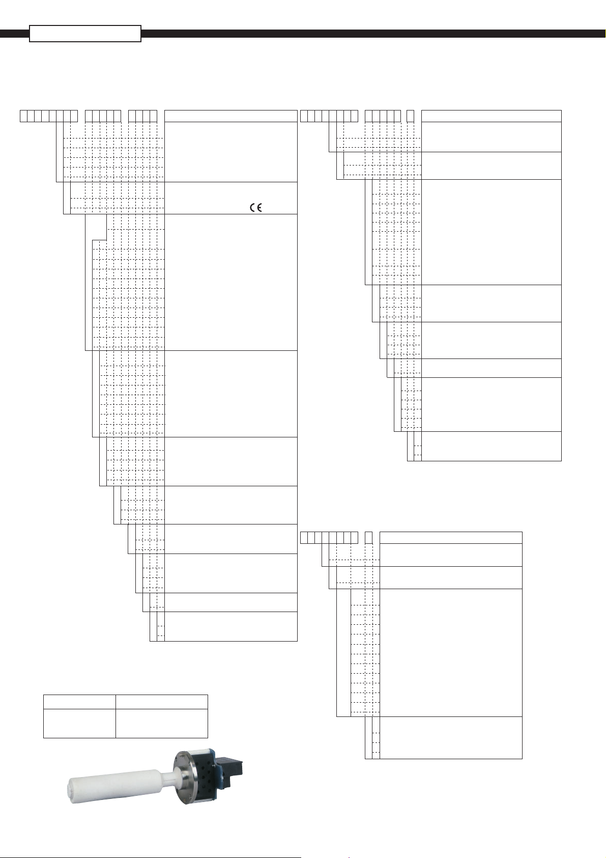
CODE SYMBOLS
(Detector)
14 15169 101112134321 5678
17
5- -KREFZ
Y
1
2
A
B
1
3
Y
0
Y
0
7
8
9
A
B
C
D
E
F
G
H
F
G
H
J
K
L
M
N
3
5
7
1
(Replacement Detector element)
Power supply Code symbols
100 to 120V AC ZFK8YY15-0Y0YY-0YY
200 to 240V AC ZFK8YY35-0Y0YY-0YY
1
Cal. gas inlet
Non (G3/8 female screw)
For F6mm tube
For F1/4 inch tube
Ejector for F6mm tube
Ejector for F1/4 inch tube
Power supply
100 to 120VAC 50/60Hz
200 to 240VAC 50/60Hz
Flow guide tube
None
<Flange size>
JIS 5K 65A
JIS 5K 80A
JIS 5K100A
JIS 10K 65A
JIS 10K 80A
JIS 10K 100A
ANSI 150LB 2B
ANSI 150LB 3B
ANSI 150LB 4B
DIN DN50 PN10
DIN DN80 PN10
<Application / meterial>
For corrosive gas / SUS316
With blow-down nozzle / SUS316
For high particular / SUS316
For high particular with cover / SUS316
For high particular / SUS310S
For high particular with cover / SUS310S
For high particular / titanium
For high particular with cover / titanium
<Length>
300mm
500mm
750mm
1000mm
Y
A
B
5
7
J
E
C
Reference gas inlet
Non (G1/8 female screw)
for F6mm tube
For F1/4 inch tube
Filter
Standard
For high particular
Instruction manual language
Japanese
English
Chinese
Specification name plate
1
Standard
Ex. Standard
N
NEPSI
T
TIIS (pending)
Description
(Converter)
910111221 345678
E
-11MKZ
1
B
E
1
2
Y
1
2
3
4
5
6
7
J
E
C
Y
1
2
1
Note1) When you select this display, rich mode
(Exclusive-special cable)
921 345678
-1ERZRZ
E
R
YA
YB
YC
YD
YE
YF
YG
YH
YJ
YK
YL
YM
Connectable devices
For Z KM E
Types
For R thermocouple
Cable length
6m
10m
15m
20m
30m
40m
50m
60m
70m
80m
90m
100m
Cable end treatment
0
None
1
One side (detector side)
2
Both sides
13
14
-
Output signal
4 to 20mA DC
0 to 1V DC
Communication function
RS-232C
RS-485
Optional Functions
None
Combustion efficiency display function Note1)
Blowdown
Auto calibration
Combustion efficiency indication
+ Blowdown Note1)
Combustion efficiency indication
+ Auto calibration Note1)
Blowdown + Auto calibration
Combustion efficiency indication + Blowdown
+ Auto calibration Note1)
Instruction manual language
Japanese
English
Chinese
Mounting Option
None (Mounting on panel surface)
With valve
With valve + flowmeter
Specification name plate
Standard
Number of Cable Gland
3
3
4
4
5
5
6
6
7
7
Ex Standard
N
NEPSI
T
TIIS (pending)
will be a simultaneous display.
Description
Description
4
Page 5
SCOPE OF DELIVERY
Detector: Detector main unit × 1, Viton Packing
× 1, thermo seal × 1, mounting screw
(M5mm × 25) × 6, flow guide tube (as
specified) × 1, Wrench × 1, Instruction
manual × 1
Converter: Converter main unit × 1, mounting
screw (M12 × 50) × 4, Cock (option) ×
1, flowmeter (option) × 1,
Accessories (AC250V 500mA T fuse ×
2, AC250V 2.5A T fuse × 2), Wrench ×
1, Instruction manual × 1
Ejector: With detector main unit (option)
Items to be prepared separately:
(1) Standard gas for calibration
Type ZBM
Type ZBM
(2) Reduction valve for standard gas (type ZBD61003)
(3) Flowmeter
Type; ZBD42203, 0.2 to 2L/min (for calibrating gas)
(unnecessary when the code 11th of ZKME is 2)
Type; ZBD42403, 1 to 10L/min (for ejector)
(4) Opner
Type; ZZP∗TK7N9329P2 (for detector; ZFKE)
Type; ZZP∗TK7N9329P1 (for converter; ZKME)
NSH4-01 (up to 5% O2 range)
NSJ4-01 (over 5% O2 range)
CAUTIONS
• If combustible gas (CO, H
gas, error will occur due to burning at the sensor section.
The inclusion of corrosive gas (Si vapor, alkaline metal, P,
Pb etc.) will shorten the life of the sensor.
• When the measured gas temperature is high (+300°C
or higher), the flange should be separated from the
furnace wall in order to bring the detector flange surface
temperature below the specified value +125°C). The
flow guide should be attached in the direction in which
the gas flow to the detector decreases.
• When much dust is included in the gas, the flow guide
tube should be attached at an inclination so that the flow
goes from below to above. And the flow guide should
be attached in the direction in which the gas flow to the
detector decreases.
• In the case of a refuse incinerator, automatic blow down
of the flow guide should not be performed (to prevent
corrosion of the flow guide tube due to drainage). Blowdown should be performed manually when change in
the indication has become very little with the furnace
stopped.
2 etc.) exists in the measured
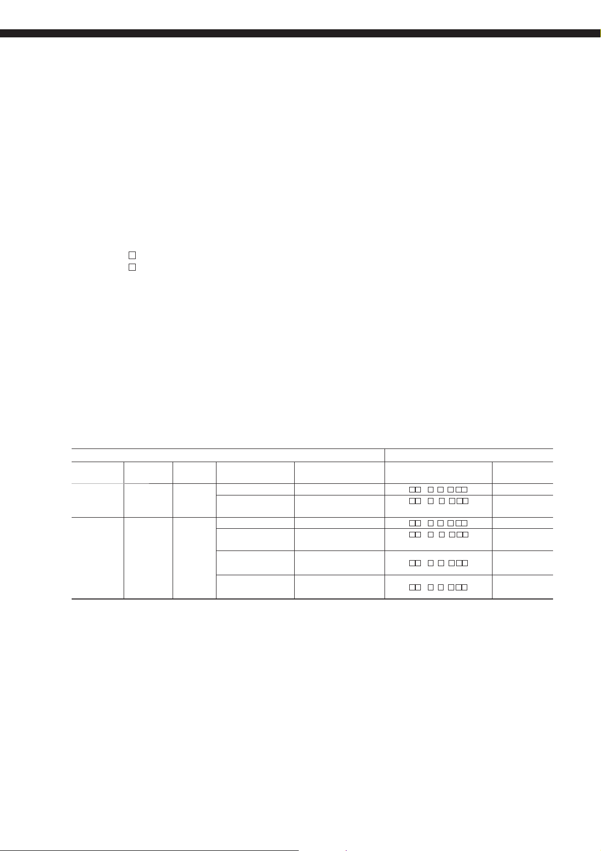
DEVICE CONFIGURATION
The device to be combined differ according to the conditions of the gas to be measured. Select the devices to be com-
bined with reference to the following table.
Measured gas Device configuration
Application Temperature Gas Flow DUST Note Detector type Converter
3
General-use
(boiler)
For corrosive
gas (refuse
incinerator)
Note (1) Dust volume is approximate value.
(2) Instrument quality air or bottled air is available as reference air by selecting detector with reference air inlet.
600ºC or
less
600ºC or
less
5 to 20m/s Less than 0.2g/Nm
Less than 10g/Nm3Fuel: coal
5 to 20m/s Less than 1g/Nm
Less than 10g/Nm3Included low moisture
Less than 25g/Nm3Included low moisture
Less than 25g/Nm3Included high moisture
Fuel; gas, oil
with blow down
3
Included low moisture
with blow down
with blow down
with blow down
ZFKER
ZFKER
ZFKER
ZFKER
ZFKER
ZFKER
5- F Y -
5- G Y -
5- F Y -
5- G Y -
H
5- K Y -
M
J
5- L Y -
N
type
ZKME
ZKME
ZKME
ZKME
ZKME
ZKME
5
Page 6

ZFKE, ZKME
CONFIGURATION
Flow guide tube system
Rc1/4
(upper side blow port should be selected)
Blow-down, 200 to 300kPa
Flow guide tube
Gas temperature.
600ºC max.
Sample gas outlet
Blue
Reduction valve
Solenoid valve
(not supplied)
(unnecessary when supply
air pressure is 200 to 300kPa
Supply air
15ASGP
tube equivalent
(not supplied)
Detector
(ZFKE)
15ASGP
tube equivalent
(not supplied)
from (1)
exhaust
AC power
123
6
45
supply
Black
Black
Red
White
Yellow
Gas temperature.
600ºC max.
Flow guide tube
for high particulate
Sample gas outlet
Gas temperature.
600ºC max.
Flow guide for high
particulate with cover
(1) to Detector
RS232C
or
RS485
(option)
φ
6mm or φ1/4 inch tube
for calibration gas
(not supplied)
*2 Ref. gas
φ
for calibration gas
(not supplied)
6mm or φ1/4 inch tube
115234567891011121314
+
O2 sensor
*4
−
O2
input
Thermocouple
for combustion
control
+
TC2
+
TC1
2 sensor
O
thermocouple
input
−
16
+
−
Analog output
4 to 20mA DC
DI1
17
AO
−
or
or
0 to 1V DC
Contact input
DI2 DI3
18 19
Fault contact
output
Alarm
contact
output
ALARM MAINTE
DICOM
21 22
20
Blow
contact
output
Maintenance
contact
output
23 24
ZV
ZERO
GAS
Calibrating gas
contact output
Calibrating gas
contact output
COM
25 28
12 3
TM-2
AC power
supply
Reduction
valve (ZBD6)
Standrad gas
for zero point
(ZBM)
Reduction valve
(unnecessary when supply air pressure is 50 to 100kPa)
Reduction vale
(ZBD6)
Flowmeter
(ZBD4)
(1.5 to 2.0L/min)
(1.5 to 2.0L/min)
Joint
Solenoid valve
(not supplied)
Solenoid valve
(not supplied)
Converter (ZKME)
O2 sensor
heater power input
AC power
SPAN
supply
GAS
NSV
26 27
*1 Air supply
AC
TM-1
L
AC power
supply
*3
PE
Span point
*1
Standard gas for
span point (ZBM)
Note:
*1 Standard gas or instrumentation air can be used in place of span gas.
*2 Instrument quality air or bottled air is available as reference gas instead of ambient air.
*3 Protective earth.
*4 Connect the shield of a exclusive cable with the ground terminal in the converter.
6
Page 7

Flow guide tube system (with valve)
Rc1/4
(upper side blow port should be selected)
Blow-down, 200 to 300kPa
Flow guide tube
from (1)
Gas temperature.
600ºC max.
123
Blue
6
Black
Red
Yellow
Sample gas outlet
Gas temperature.
600ºC max.
45
White
Black
15ASGP
tube equivalent
(not supplied)
Detector
(ZFKE)
exhaust
AC power
supply
Solenoid valve
(not supplied)
Reduction valve
(unnecessary when supply
air pressure is 200 to 300kPa
15ASGP
tube equivalent
(not supplied)
Supply air
Flow guide tube
for high particulate
Sample gas outlet
Gas temperature.
600ºC max.
Flow guide for high
particulate with cover
φ
6mm or φ1/4 inch tube
for calibration gas
(not supplied)
(1) to Detector
RS232C
or
RS485
(option)
*2 Ref. gas
φ
6mm or φ1/4 inch tube
for calibration gas
(not supplied)
115234567891011121314
+
O2 sensor
*4
−
O2
input
Thermocouple
for combustion
control
+
TC2
+
TC1
2 sensor
O
thermocouple
input
−
16
+
−
Analog output
4 to 20mA DC
DI1
17
AO
−
or
or
0 to 1V DC
Contact input
DI2 DI3
18 19
Fault contact
output
Alarm
contact
output
ALARM MAINTE
DICOM
21 22
20
Blow
contact
output
Maintenance
contact
output
23 24
ZV
ZERO
GAS
Calibrating gas
contact output
Calibrating gas
contact output
COM
25 28
12 3
TM-2
Flowmeter
(option)
Flowmeter
(ZBD4)
(1.5 to 2.0L/min)
(1.5 to 2.0L/min)
Valve
(option)
MEASURE
SPAN
ZERO
Reduction
valve (ZBD6)
Standrad gas
for zero point
(ZBM)
Reduction vale
(ZBD6)
Converter (ZKME)
O2 sensor
heater power input
AC power
SPAN
supply
GAS
NSV
26 27
*1 Air supply
AC
TM-1
L
AC power
supply
*3
PE
Note:
*1 Standard gas or instrumentation air can be used in place of span gas.
*2 Instrument quality air or bottled air is available as reference gas instead of ambient air.
*3 Protective earth.
*4 Connect the shield of a exclusive cable with the ground terminal in the converter.
Span point
*1
Standard gas for
span point (ZBM)
7
Page 8

ZFKE, ZKME
Flow guide tube system (with ejector)
Rc1/4
(upper side blow port should be selected)
Blow-down, 200 to 300kPa
Flow guide tube
from (1)
Gas temperature.
600ºC max.
Flowmeter
Blue
(ZBD4)
(5 to 10L/min)
6
Black
Yellow
123
Red
45
Calibrating gas
Sample gas outlet
exhaust
White
Black
from (2)
15ASGP
tube equivalent
(not supplied)
Detector
(ZFKE)
exhaust
AC power
supply
Solenoid valve
(not supplied)
Reduction valve
(unnecessary when supply
air pressure is 200 to 300kPa
Supply air
15ASGP
tube equivalent
(not supplied)
Gas temperature.
600ºC max.
Flow guide tube
for high particulate
Sample gas outlet
Gas temperature.
600ºC max.
Flow guide for high
particulate with cover
(1) to Detector
RS232C
or
RS485
(option)
φ
6mm or φ1/4 inch tube
for calibration gas
(not supplied)
*2 Ref. gas
φ
for calibration gas
(not supplied)
6mm or φ1/4 inch tube
115234567891011121314
−
O2
input
Thermocouple
for combustion
control
+
TC2
+
TC1
2 sensor
O
thermocouple
input
−
+
O2 sensor
*4
16
+
−
Analog output
4 to 20mA DC
DI1
17
AO
−
or
or
0 to 1V DC
Contact input
DI2 DI3
18 19
Fault contact
output
Alarm
contact
output
ALARM MAINTE
DICOM
21 22
20
Blow
contact
output
Maintenance
contact
output
23 24
ZV
ZERO
GAS
Calibrating gas
contact output
Calibrating gas
contact output
COM
25 28
12 3
TM-2
AC power
supply
Standrad gas
for zero point
(ZBM)
Reduction valve
(unnecessary when supply air pressure is 50 to 100kPa)
Flowmeter
(ZBD4)
(1.5 to 2.0L/min)
Joint
Solenoid valve
(not supplied)
(2) to ejector
Reduction
valve (ZBD6)
Joint
(0.2 to 0.5L/min)
Solenoid valve
(not supplied)
Reduction vale
(ZBD6)
Converter (ZKME)
O2 sensor
heater power input
SPAN
GAS
26 27
*1 Air supply
AC power
supply
AC
NSV
TM-1
L
AC power
supply
*3
PE
Span point
*1
Standard gas for
span point (ZBM)
Note:
*1 Standard gas or instrumentation air can be used in place of span gas.
*2 Instrument quality air or bottled air is available as reference gas instead of ambient air.
*3 Protective earth.
*4 Connect the shield of a exclusive cable with the ground terminal in the converter.
8
Page 9

Flow guide tube system (with ejector+valve)
Rc1/4
(upper side blow port should be selected)
Blow-down, 200 to 300kPa
Flow guide tube
from (1)
Gas temperature.
600ºC max.
Flowmeter
Blue
6
Black
Yellow
(ZBD4)
(5 to 10L/min)
123
Red
from (2)
45
Black
White
Calibrating gas
Sample gas outlet
exhaust
15ASGP
tube equivalent
(not supplied)
Detector
(ZFKE)
exhaust
AC power
supply
Solenoid valve
(not supplied)
Reduction valve
(unnecessary when supply
air pressure is 200 to 300kPa
Supply air
15ASGP
tube equivalent
(not supplied)
Gas temperature.
600ºC max.
Flow guide tube
for high particulate
Sample gas outlet
Gas temperature.
600ºC max.
Flow guide for high
particulate with cover
(1) to Detector
RS232C
or
RS485
(option)
φ
6mm or φ1/4 inch tube
for calibration gas
(not supplied)
*2 Ref. gas
φ
for calibration gas
(not supplied)
6mm or φ1/4 inch tube
115234567891011121314
−
O2
input
Thermocouple
for combustion
control
+
TC2
+
TC1
2 sensor
O
thermocouple
input
−
+
O2 sensor
*4
16
+
−
4 to 20mA DC
DI1
17
AO
or
Analog output
or
0 to 1V DC
Contact input
DI2 DI3
18 19
−
Fault contact
output
ALARM MAINTE
DICOM
20
Alarm
contact
output
21 22
Blow
contact
output
Maintenance
contact
output
23 24
ZV
ZERO
GAS
Calibrating gas
contact output
Calibrating gas
contact output
COM
25 28
12 3
TM-2
Flowmeter
(option)
Flowmeter
(ZBD4)
(1.5 to 2.0L/min)
(0.2 to 0.5L/min)
Valve
(option)
MEASURE
SPAN
ZERO
Reduction
valve (ZBD6)
Standrad gas
for zero point
(ZBM)
Reduction vale
(ZBD6)
Converter (ZKME)
O2 sensor
heater power input
AC power
SPAN
supply
GAS
AC
NSV
26 27
*1 Air supply
TM-1
L
AC power
supply
*3
PE
Note:
*1 Standard gas or instrumentation air can be used in place of span gas.
*2 Instrument quality air or bottled air is available as reference gas instead of ambient air.
*3 Protective earth.
*4 Connect the shield of a exclusive cable with the ground terminal in the converter.
Span point
*1
Standard gas for
span point (ZBM)
9
Page 10

ZFKE, ZKME
OUTLINE DIAGRAM
(Unit:mm)
Y
Detector (ZFKER )
1
2
Approx. 215
17.5
77
P
View B
Filter
Approx. 126
Approx. 162
32
Approx.
Calibration gas inlet (To order)
SUS316, for φ6mm tube
(the 6th digit is “1”)
Or 1/4 inch tube
(the 6th digit is “2”)
(Not provided if the 6th digit is “Y”)
Ref. gas inlet (to order)
SUS316, for
(the 13th digit is “A”)
or 1/4 inch tube
(the 13th digit is “B”)
Exclusive Cable gland
(For power supply)
Exclusive Cable gland
100
φ
Approx.
φ
6mm tube
(For signal)
Approx.
180
Approx. 152
Approx.
140
Approx. 242
Lock screw M6
External ground
terminal M4
Explotion-proof
name plate
View A
6-
φ
6
VIEW FROM P
Sensor unit (ZFK8YY)
(132.7)
(88.4) 3.5
67
φ
(14th digt code 7)(13th digt code A, B)
VIEW A VIEW B
EXTERNAL
CONNECTION DIAGRAM
Thermocouple
Heater
1
2-core wire 4-core wire
Exclusive-special cable
2
Black
3
Red White
Element output
45 6
Yellow BlueBlack
10
17.5)
φ
(
20
4-φ3.5(Mount for detector)
TK4J4664R0
45°
45°
T+
S+
φ
35
40
6
madeinjapan
5
S-
H
1
3
4
2
H
T-
Page 11

Detector (ZFKER )
A
B
Ref. gas inlet (to order)
SUS316, for
Or 1/4inch tube (the 13th digit is “B”)
φ
6mm tube (the 13th digit is “A”)
P
View B
Filter
Calibration gas inlet
SUS316, for φ6mm tube
(the 6th digit is “A.”)
1/4 inch tube (the 6th digit is “B.”)
Ejector gas outlet
SUS316, for φ6mm tube
(the 6th digit is “A.”)
1/4 inch tube (the 6th digit is “B.”)
Approx. 185
6-
126
Approx.
Approx. 57
φ
6
Approx. 215
17.5
77
Approx. 100
Exclusive Cable gland
Calibration
Air out
Approx. 47
Air in
Approx. 37
Approx. 78
Approx. 21
(For power supply)
Exclusive Cable gland
Ejector gas inlet
SUS316, for
(the 6th digit is “A.”)
1/4 inch tube (the 6th digit is “B.”)
67
φ
φ
6mm tube
(For signal)
Approx.
155
Approx. 140
Explotion-proof
name plate
Approx. 242
Approx. 180
(14th digt code 7)(13th digt code A, B)
VIEW A VIEW B
Lock screw M6
View A
External ground
terminal M4
EXTERNAL
CONNECTION DIAGRAM
Heater
Thermocouple
1
2-core wire 4-core wire
Exclusive-special cable
2
Black
3
Red White
Element output
45 6
Yellow BlueBlack
VIEW FROM P
Flow guide tube (with blow-down nozzle) (ZFKE: 10th digit code. G)
t
f
ZFKE MTG. position
Code 11th
L (m)
Mass
Approx.(kg)
Approx. L
60.5
Gas inlet
Gas outlet
3
571
0.5 0.75 1.0
0.3
3.8
3.0
Approx. 20
5.7
4.8
6-M5
detector side
Z
L=
(to order)
Blow down
air inlet
D
C
67
N– h
MTG. holes
4-Rc1/4
with plug int.thd.
Flange size
JIS 5K 65A
JIS 5K 80A
JIS 5K 100A
JIS 10K 65A
JIS 10K 80A
JIS 10K 100A
ANSI 150LB 2B
ANSI 150LB 3B
ANSI 150LB 4B
DIN DN50 PN10
DIN DN80 PN10
Code
9th
7
8
9
A
B
C
D
E
F
G
H
DCt f Nh
155
130
145
165
140
150
175
120.7
152.4
190.5
125
160
14
14
16
18
18
18
17.5
22.3
22.3
18
20
180
200
175
185
210
150
190
230
165
200
2
110
2
121
2
141
2
116
2
126
2
151
2
92.1
2
127
2
157.2
0
0
0
0
15
4
19
4
19
8
19
4
19
8
19
8
19.1
4
19.1
4
19.1
8
18
4
18
4
11
Page 12

ZFKE, ZKME
Flow guide tube (for high particulate) (ZFKE: 10th dight code. H, K, M)
4 - Rc 1/4
with plug int thd.
ZFKE MTG.
position
D
C
Blow down air inlet
Select an upper port to
avoid the condensation
in the piping
N - h
MTG. hole
67
38.5
t
Packing
Gas
outlet
Code 11th
188
L
50
L (m)
Mass
Approx.(kg)
3
0.3
4.5
0.5 0.75 1.0
5.6
30
57
7.0
1
8.3
Z
L=
(to order)
Gas flow
Flange size
JIS 5K 65A
JIS 5K 80A
JIS 5K 100A
JIS 10K 65A
JIS 10K 80A
JIS 10K 100A
ANSI 150LB 2B
ANSI 150LB 3B
ANSI 150LB 4B
DIN DN50 PN10
DIN DN80 PN10
Code
9th
7
8
9
A
B
C
D
E
F
G
H
DCt f Nh
155
180
200
175
185
210
150
190
230
165
200
130
145
165
140
150
175
120.7
152.4
190.5
125
160
14
14
16
18
18
18
17.5
22.3
22.3
18
20
2
110
2
121
2
141
2
116
2
126
2
151
2
92.1
2
127
2
157.2
0
0
0
0
4
4
8
4
8
8
4
4
8
4
4
Flow guide tube (for high particulate with cover) (ZFKE: 10th dight code. J, L, N)
4 - Rc 1/4
with plug int thd.
D
C
Blow down air inlet
Select an upper port to
avoid the condensation
in the piping
N - h
MTG. hole
67
38.5
15
19
19
19
19
19
19.1
19.1
19.1
18
18
ZFKE MTG. position
Packing
Gas flow
12
Production
tube
(38)
Gas
outlet
L
(L-10)
t
(178)
50
30
Code 11th
L (m)
Mass
Approx.(kg)
3
0.3
7.1
0.5 0.75 1.0
9.0
57
11. 4
1
13.6
Z
L=
(to order)
Page 13

Flow guide tube (ZFKE: 10th dight code. F)
t
Approx. L
f
Gas inlet
60.5
Approx.
40
D
C
67
ZFKE MTG. position
Code 11th
MASS
Approx.(kg)
Coverter (ZKME)
Lock screw M6
ZKM
Oxygen Analyzer
442
362
402
L (m)
Gas outlet
3
571
0.5
0.3
3.3
4.5
Mounting hole 4-ø14
326
286
㻹㻻㻰㻱
㻱㻿㻯
ὀࠉព
ኚჾ౪⤥ࡍࡿ㟁※㟁ᅽࡣࠊ᥋⥆ࡉࢀࡿ
᳨ฟჾࡢ㟁※㟁ᅽྜࢃࡏ࡚ࡃࡔࡉ࠸ࠋ
㹁㸿㹓㹒㹇㹍㹌
3RZHUVXSSO\PXVWEHVHOHFWHG
WKHVDPHYROWDJHRIGHWHFWRU
7&
$2
2
)$8/7
㸩
㸩
㸩
㸫
㸫
㸫
%/2:
0$,1
$/$50
',
7&
', ', ',
㸩
㸫
7(1$1&(
&20
0.75
6.1
㻱㻺㼀㻱㻾
=9 +($7(5
&2069
㻻㼤㼥㼓㼑㼚㻌㻭㼚㼍
㻼㻻㼃㻱㻾
32:(5
)86(7$
+($7(5
)86(7$
21
32:(5
2))
$&
1
6-M5
detector side
Z
1.0
L=
(to order)
7.6
/
N- h
MTG. holes
Flange size
JIS 5K 65A
JIS 5K 80A
JIS 5K 100A
JIS 10K 65A
JIS 10K 80A
JIS 10K 100A
ANSI 150LB 2B
ANSI 150LB 3B
ANSI 150LB 4B
DIN DN50 PN10
DIN DN80 PN10
Code
9th
7
8
9
A
B
C
D
E
F
G
H
DCt f Nh
211
155
180
200
175
185
210
150
190
230
165
200
130
145
165
140
150
175
120.7
152.4
190.5
125
160
17
14
14
16
18
18
18
17.5
22.3
22.3
18
20
2
110
2
121
2
141
2
116
2
126
2
151
2
92.1
2
127
2
157.2
0
0
0
0
15
4
19
4
19
8
19
4
19
8
19
8
19.1
4
19.1
4
19.1
8
18
4
18
4
68
Ground terminal M4
For communication
186
40
For sensor signal
(6&
02'(
For contact In/Out
60 60 60
For sensor power
&$87,21
:+(123(17+,6&29(5
32:(52))$1'.((3287
(;3/26,9($70263+(5(
)XML(OHFWULF,QVWUX
PHQ
WDWLRQ&R/WG
60 60
For output
(17
Cable gland for flame proof ø9 - ø12 /
closeup plug (To order)
For Other
52
For power
supply
)XML(OHFWULFV\VWHPV&R/WG
)XML(OHFWULF,QVWUXPHQWV&R/WG
13
Page 14

ZFKE, ZKME
Ground
terminal
M4
EXTERNAL TERMINAL (TM1) /M3
sensor
O
O2 sensor
Exclusive
cable
input
115234567891011121314
++
O
2
2
thermocouple
input
−
+
TC2
+
−
16
Thermocouple
input type R
(not supplied)
Analog
output
4-20mA DC
or 0-1V DC
AO
−
TC1
DI1
17
Contact input
Short circuit : on (Current 5mA)
Open : off (Voltage 5V)
−
or
DI2 DI3
18 19
Fault
contact output
250V AC/3A
30V DC/3A
FAULT
ALARM MAINTE
DICOM
21 22
20
Alarm
contact output
250V AC/3A
30V DC/3A
Blow contact
output
250V AC/3A
30V DC/3A
BLOW
COM
ZV
ZERO
23 24
Maintenance
contact output
250V AC/3A
30V DC/3A
O
heater power
GAS
HEATER
25 28
Calibrating gas
contact output
250V AC/3A
30V DC/3A
COMMUNICATION TERMINAL (TM2) /INSERTION TERMINAL
sensor
2
output
SPAN
GAS
26 27
AC
L
NSVCOM
AC
Power supply
input
100 to120V AC
200 to 240V AC
RS232C
RS485
Terminal number
1
2
TXD
RXD
TRX+
TRX–
3
GND
GND
Remarks
Standard
Option
14
Page 15

OUTLINE DIAGRAM
(Unit:mm)
<Option>
SELECTOR VALVES + FLOWMETER (IN CASE OF 11TH DIGIT CODE “2” )
293
SPAN
114
ZERO
MEA RE
102
Zero gas inlet
126
(NPT1/8)
φ
2-
5.5
Mounting hole
CALIB.
6
15
ZERO
20
20
30
83
SPAN
20
Span gas inlet (NPT1/8)
Calibration gas outlet (NPT1/8)
65
SELECTOR VALVES (IN CASE OF 11TH DIGIT CODE “1” )
SPAN
2-φ5.5
Mounting hole
114
102
6
ZERO
MEA RE
CALIB.
ZERO
20
15
30
20
83
SPAN
Zero gas inlet
(NPT1/8)
20
Span gas inlet (NPT1/8)
101
65
Calibration gas outlet (NPT1/8)
65
15
Page 16

ZFKE, ZKME
Caution on Safety
*Before using this product, be sure to read its instruction manual in advance.
International Sales Div.1
Sales Group
Gate City Ohsaki, East Tower, 11-2, Osaki 1-chome,
Shinagawa-ku, Tokyo 141-0032, Japan
http://www.fesys.co.jp/eng
Phone: 81-3-5435-7280, 7281 Fax: 81-3-5435-7425
http://www.fic-net.jp/eng
Information in this catalog is subject to change without notice.
Printed in Japan
 Loading...