

Page 1
Instruction Manual
THE DIRECT INSERTION TYPE
ZIRCONIA OXYGEN
ANALYZER DETECTOR
TYPE: ZFKE
INZ-TN5ZFKE-E
Page 2

PREFACE
Thank you very much for your kind purchase of Fuji’s explosion-proof zirconia oxygen analyzer detector (Type
ZFKE).
• Read this instruction manual carefully to get a thorough understanding of how this zirconia oxygen analyzer
works prior to installing, operating and maintaining the zirconia oxygen analyzer.
If abused, unnecessary troubles or failure could occur.
• The specifi cation of this zircoia oxygen analyzer may be subject to change without previous notice for improvements of the product.
• Under no circumstances should this zirconia oxygen analyzer be modifi ed without permission.
If any trouble should occur because of having been modifi ed without permission, we won’t be responsible
for it anyway.
• This instruction manual should be kept in custody by a person who operates the zirconia oxygen analyzer
actually.
• After reading this manual, it should always be kept in a place which allows the person who operates it to
refer to any time as requirfed.
• A due consideration should be given so that this instruction manual is delivered to a fi nal user certainly.
Manufacturer : Fuji Electric Instrumentation Co., Ltd.
Type : Described in the nameplate put on the main body
Date of manufacture : Described in the nameplate put on the main body
Product nationality : Japan
Related instruction manuals
Direct insertion type explosion-proof zirconia oxygen analyzer detector (Type : ZKME) ...... INZ-TN1ZKME-E
Fuji Electric Systems Co., Ltd. 2009
NOTE
• It is prohibited to transfer a part or all of the contents of this manual
without permission.
• The contents of this manual may be subject to change in future without previous notice
©
Issued in May, 2009
i
Page 3
SAFETY PRECAUTIONS
Prior to operating the detector, read this “Safety precautions” carefully for correct use.
• In the precautions shown here, important contents on safety are included. So, be sure to observe them. The safety
precautions have been ranked into “DANGER” and “CAUTION”.
DANGER
CAUTION
: I
If the apparatus is abused, a dangerous condition could arise and it is supposed to
:
PROHIBITION:
DANGER
CAUTION
• When this product is mounted on a furnace which is under operation, take
• In the case of the wiring work, be careful not to drop foreign matters including
• Connect a power source compatible with the specifi ed rating. Connection of
• Before doing the wriring work, be sure to turn off the main power. Otherwise,
• Use proper wiring materials according to the rating of apparatus. If a wiring
:
:
f this apparatus is abused, a dangerous condition could come about and it is
supposed to die or get a serious injury.
get medium injury or a minor injury and a physical damage is supposed to occur.
This indicates a prohibition (act which must not do).
Precautions in installing and wiring
• Although this is explosion-proof type, do not use it in the place where explosive gases always exist (zone 0) to prevent explosion, fi re or otherserious
accidents.
• Install this product in a place compatible with the conditions set forth in
“instruction manual”. The use at a place not conforming to the installation
conditions may result in an electric shock, a fi re and a malfunction.
utmost care with blow-out from the furnace. There is a risk of burn injury.
wire chips into the product. Otherwise, a fi re, failure or malfunction may
result.
power source different from the rating might cause a fi re.
it results in getting an electric shock as the case may be.
material which is not bearable to the rating is employed, it might cause a fi re.
• Never do the work at a place where the product getsw wet with rain directly.
PROHIBITION:
A failure to observe this instruction may result in getting an electric shock or
failure.
ii
Page 4
Precautions in operation, stop, maintenance and check
DANGER:
CAUTION:
• The operating temperature of the detector (tip of ceramic heater) is about 800
Otherwise, there is a fear of getting a burn.
• Before cleaninhg the fl ow guide tube, turn off the main power and cool the
There is a fear of getting a burn.
• Don’t use any other renewal part than those designated by the maker. Other-
• Dispose of the renewal parts such as the maintenance parts as an incombustible
PROHIBITION:
A failure to observe this instruction may result in getting an electric shock or
• In case where combustible gas is contained in the measured gas, check the gas
composition and specifi cations carefully before using. Otherwise, the original
performance is not displayed, and there is a fear of explosion.
• Do the work in a condition where the main power has been turned off. If the
work is done while current is fl owing, there is a fear of getting an electric
shock.
°C and the surface temperature is also very high. So, never touch the detector
by bare hand.
tube down fully.
wise, the original performance is not fully displayed and an accident or failure
may result.
article.
• Never do the work at a place where rain water splases the product directly.
failure.
CAUTION:
Other precaution
• For a failure which cannot be judged even if referring to the instruction manual,
be sure to ask the nearest dealer or Fuji adjustment serviceman for repair. If
dissasembled carelessly, an accident or injury could result.
iii
Page 5

CONTENTS
PREFACE ......................................................................................................................................... i
SAFETY PRECAUTIONS .............................................................................................................. ii
1. Introduction .............................................................................................................................. 1
1.1 General description of zirconia oxygen analyzer ........................................................................1
1.2 Description of fl ameproof ..........................................................................................................1
1.3 Device confi guration of direct insertion type oxygen analyzer ...................................................1
1.4 Description of each component ...................................................................................................2
1.5 Check of type ...............................................................................................................................2
1.6 Check of delivered articles ..........................................................................................................2
2. Mounting .................................................................................................................................. 3
2.1 Mounting location .......................................................................................................................3
2.2 Mounting method ........................................................................................................................3
3. Piping ....................................................................................................................................... 7
3.1 Piping of calibration gas ..............................................................................................................7
3.2 Piping of reference gas inlet ........................................................................................................7
3.3 Piping for blow down air .............................................................................................................7
3.4 Piping drawing ............................................................................................................................8
4. Wiring ..................................................................................................................................... 12
4.1 Before wiring .............................................................................................................................12
4.2 How to open the cover ...............................................................................................................13
4.3 Wiring to each terminal .............................................................................................................13
5. Operation and Stop ................................................................................................................. 15
5.1 Start of operation .......................................................................................................................15
5.2 Stop of operation .......................................................................................................................15
6. Maintenance and Check ......................................................................................................... 16
6.1 Check .........................................................................................................................................16
6.2 Maintenance ..............................................................................................................................17
6.3 Standard output of detector .......................................................................................................19
6.4 Arrangement ..............................................................................................................................20
7. TROUBLESHOOTING ......................................................................................................... 22
8. Appendix ................................................................................................................................ 23
8.1 Specifi cation ..............................................................................................................................23
8.2 Designation of type (code table) ...............................................................................................25
8.3 DEVICE CONFIGURATION .................................................................................................27
8.4 OUTLINE DIAGRAM (Unit:mm) .........................................................................................28
iv
Page 6
1. INTRODUCTION
1.1 General description of zirconia oxygen analyzer
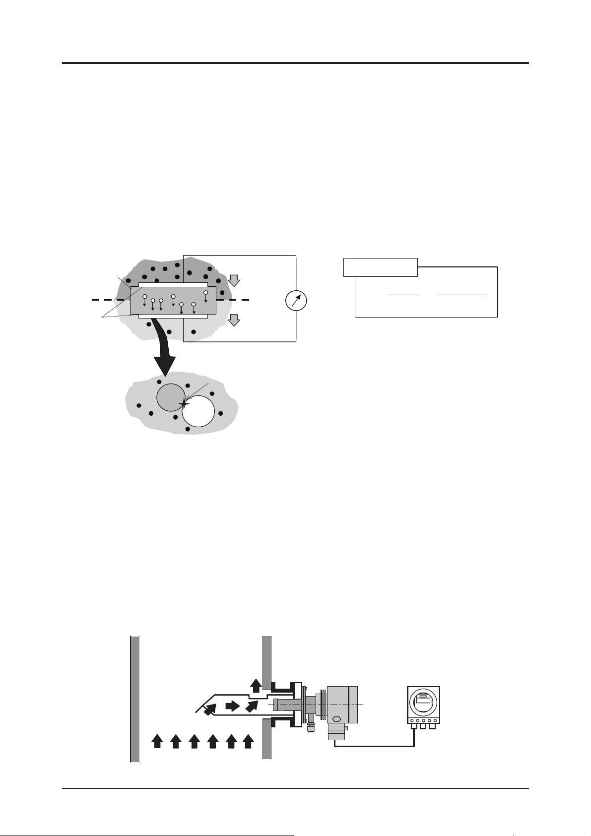
This zirconia oxygen analyzer makes use of the oxygen ion conductivity of solid electrolytes composed
mainly of zirconia (ZrO2) at high temperatures.
If electrodes of platinum or the like are attached to both faces of a solid electrolyte and the faces are on the
conditions of different oxygen partial pressures, an electrochemical reaction causes an electromotive force
between both the electrodes. This phenomenon is called concentration cell action.
Microscopically, it is assumed that electrochemical reactions occur at the interface (three-phase interface)
among a solid electrolyte, electrode and oxygen.
High-oxygen partial pressure side: O2 + 4e– → 2O2– (ionization)
Low-oxygen partial pressure side: 2O2– → O2 + 4e– (molecularization)
An electromotive force (E) generated is expressed as follows with Nernst’s equation:
High-oxygen partial
pressure side P
Solid electrolyte
Electrode
Low-oxygen partial
pressure side P
H
L
Zirconia
Oxygen molecule
2-
2-
O
O
Platinum
O
2
Ionization
Molecularization
O
2
Three-phase interface:
a part where electrochemical
reactions occur.
Electromotive
force
Nernst’s equation
E : Electromotive force
P
reference gas (atmosphere)
PL(O2) : Oxygen partial pressure of a
measured gas
R : Gas constant 8.3144[J・mol-1・K-1]
T : Absolute temperature[K]
F : Faraday constant 9.649×10⁴[c・mol-1]
P
P
H(O2
L(O2
E= 1n
H(O2
RT
4F
) : Oxygen partial pressure of a
)
)
1.2 Description of fl ameproof
Flameproof is the unit that has passed the test conducted by the public institution as an fl ameproof-structured
instrument.
A test certifi cate and a name plate including necessary specifi cations for the purpose of explosion-proof are
attached to such an accepted unit.
Confi rm them and use the unit according to those contents.
On the name plate for instrument of fl ameproof, the 17th digit of type code, either with N for China or T for
Japan, is stated.
The certifi cation mark by public institution is also attached.
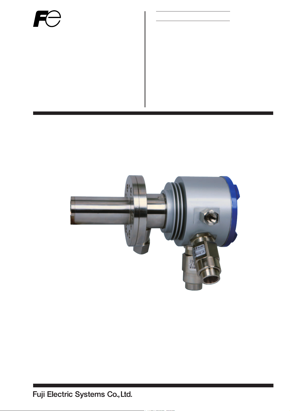
1.3 Device confi guration of direct insertion type oxygen analyzer
The direct insertion type zirconia oxygen analyzer consists of the detector with a sensor unit, the fl ow guide
tube that is directly inserted to the stack or the like in order to supply a gas to the detector, and the converter
that performs sensor control, signal processing, output/display, and external transmission. The detector and
converter are connected with a cable.
Stack
Flow guide tube
ConverterDetector
Flow of gas
Cable
(sensor output line, thermocouple output line,
heater power wire)
1
Page 7
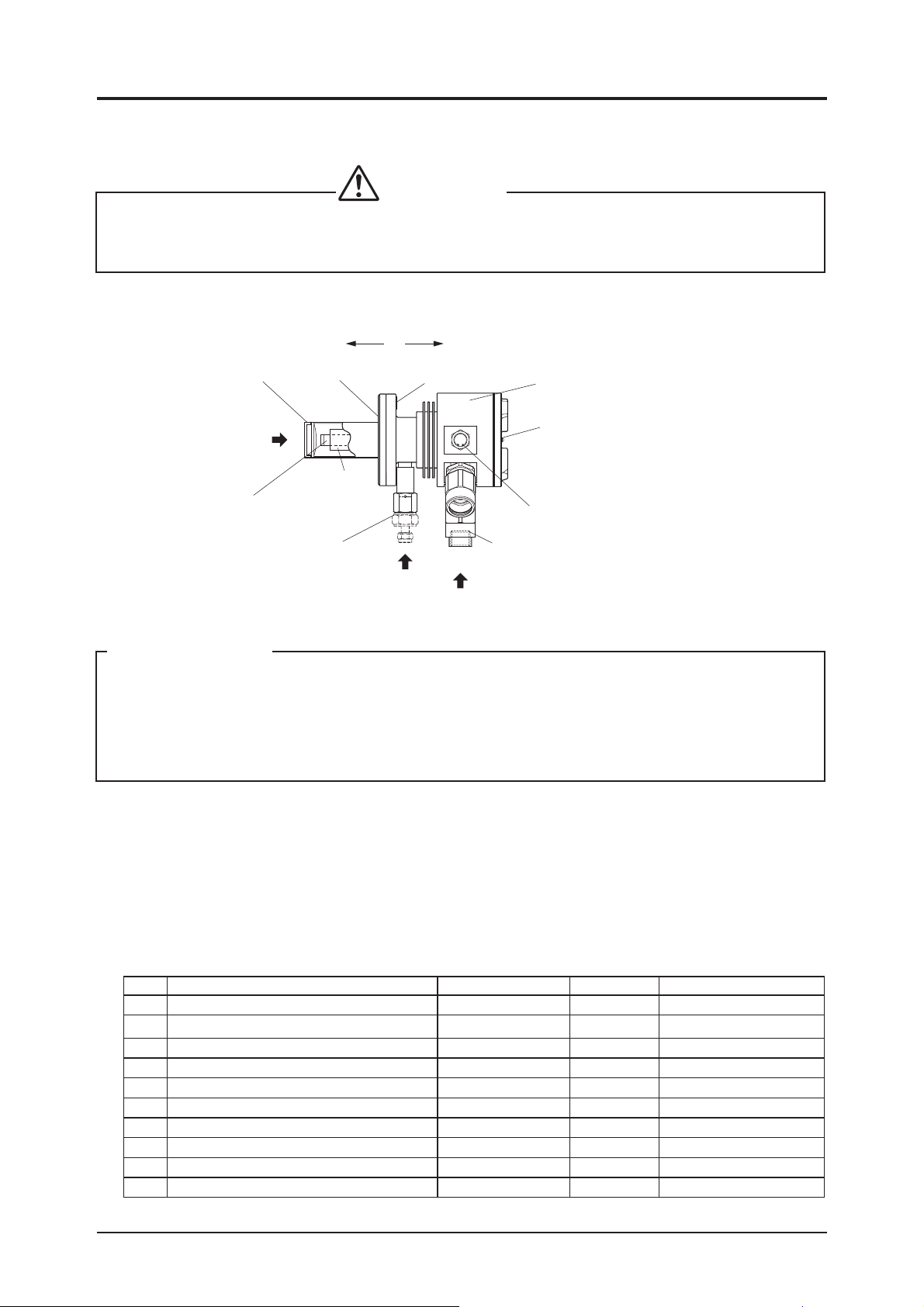
1.4 Description of each component
CAUTIONS
• The operating temperature of detector (tip of ceramic heater) is about 800°C and the surface temperature is also very high. So, never touch it by bare hand. Otherwise, there is a fear of getting a burn.
Especially when a fi lter at the end of the detector is replaced, take utmost care.
(1) ZFKE
Furnance environment
(Gas to be measured)
Filter cap
Measured gas
Ceramic heater
Joint for calibration gas
Packing
Heat insulating
material
Thermo sticker
Calibration
gas inlet
Air environment
(Reference gas)
Terminal box
Terminal box lid
Hexagon plug or reference gas inlet
* According to designation of type
Dedicated cable gland
Wiring hole
Caution in handling
• Since the detector is made of porcelain of zirconia, there is a case where it breaks due to drop or
impact. So, be suffi ciently careful.
• The detector is unusable for a plant in which water droplets might run down inside a sampling pipe.
• There is no need to remove M5-hexagon set screw of the terminal box unless otherwise a reference
gas inlet is used. Don’t loosen the screw without thought since a waterproofi ng effect becomes zero.
1.5 Check of type
The name of type has been put in the specifi cation name-plate. Make sure it is as ordered.
Refer to Item 8.2 “Desingation of type”.
1.6 Check of delivered articles
Make sure the following articles have been delivered without lack.
No. Description
Detector 1 unit Confi rmed in Item 1.3
1
Instruction manual (this manual) 1 copy INZ-TN5ZFKE-E
2
3 Packing
Mounting screw, plain & spring washer (M5) Accessories 6 pcs each See Item 2.2.1.
4
Thermo sticker Specifi cation goods 1 sh. See Item 2.2.1.
5
6 Filter cap
7 Spring
8 Hexagonal wrench
Flow guide tube Specifi cation goods As ordered See Item 6.2.2 and 2.2.3.
9
Reference gas inlet Specifi cation goods As ordered See Item 3.2.
10
Classifi cation Q'ty Remark
Accessories 1 sheet See Item 2.2.1.
Specifi cation goods 1 piece See Item 6.2.2
Specifi cation goods 1 piece See Item 6.2.2
Accessories 1 piece See Item 2.2.1
2
Page 8
2. MOUNTING
2.1 Mounting location
DANGER
• Although this is explosion-proof type, do not use it in a place where explosive gases always exist (zone
0) to prevent explosion, fi re or other serious accidents.
CAUTIONS
• Install this product at a place compatible with the following conditions. The use of it at a place not
conforming the installation conditions specifi ed in this manual could cause an electric shock, a fi re
or incorrect operation.
Mount the detector by selecting the places shwon below:
1 Place where there is a space which allows doing daily check and wiring work
2 Place where there is little vibration (acceleration: 2 m/s2, frequency: within 5 to 100 Hz), dust and hu-
midity (equivalent to IP65 or less)
3 Place where peripheral air environment is non-corrosive.
4 Place where there are no electric appliances producing noise trouble (For example : motor, transformer
and appliances bringing about electromagnetic induction trouble and electrostatic induction trouble)
nearby the detector.
5 Place where ambient temperatue and humidity are -10 to +60°C and less than 95% RH .
2.2 Mounting method
CAUTIONS
• When mounting the detector on a furnace which is under operation, take utmost care about the
blowout from the furnace; otherwise, there is a fear of getting a burn.
3
Page 9
2.2.1 Mounting method of detector
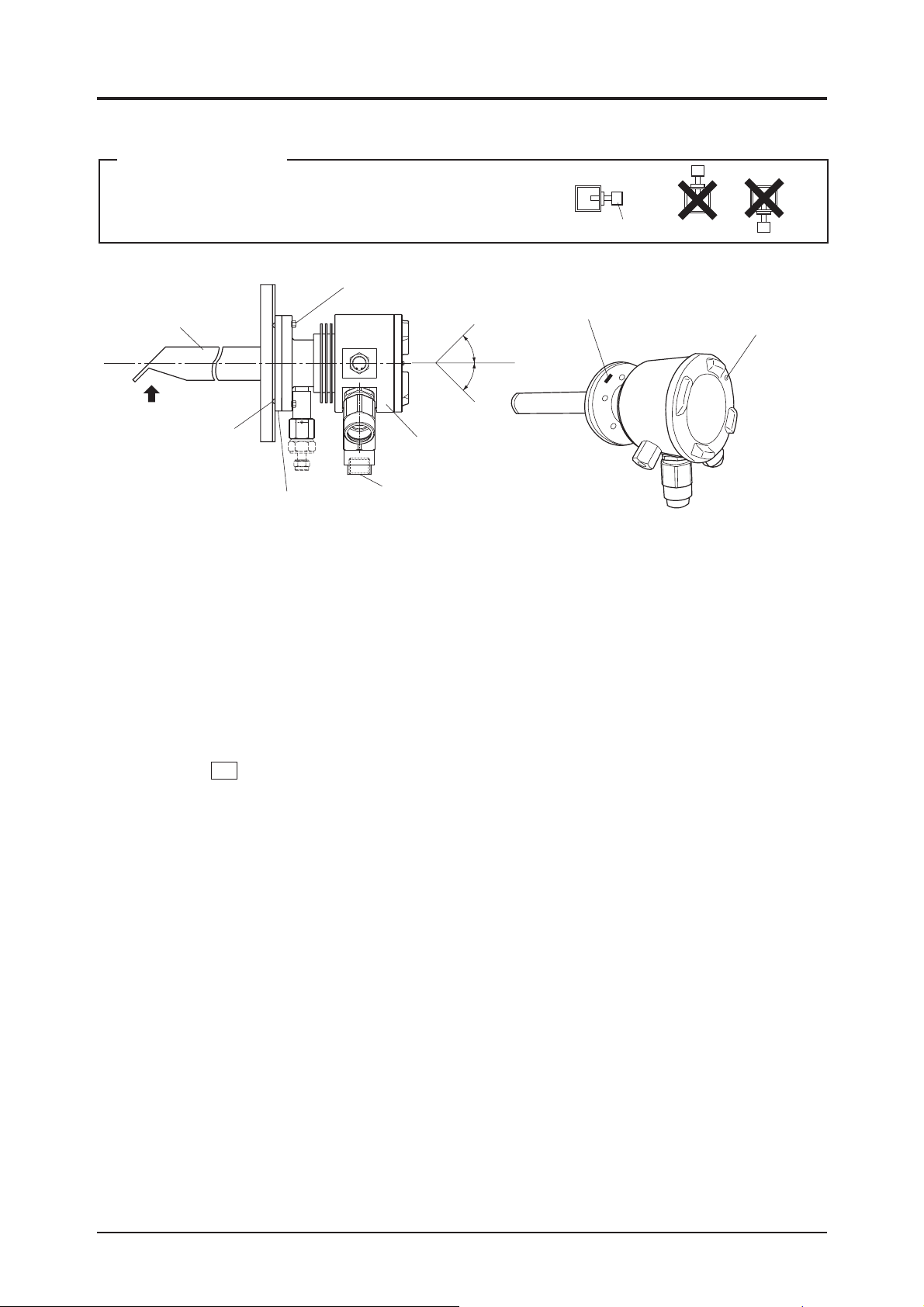
Caution in mounting
Up
Up Up
• Never mount the detector with the tip turned upward or
downward. A failure of the detector may result.
Flow guide tube
Gas flow
Packing
(accessory)
Mounting screw (accessory)
Detector flange
+45°
-45°
Detector
Wiring hole
Down
Thermo sticker
Detector
Down Down
Fixing screw for cover
(use an attached
hexagonal wrench)
1 Attach the packing (accessory, Viton P36) to the detector fl ange. Subsequently, attach the detector to
the fl ange of the fl ow guide tube by fi xing the mounting screws (accessory, M5) and the fl at and spring
washers (accessories) to the three locations (at the opposing corners of six mounting holes) (recommended
tightening torque: 3.5 N · m).
2 Attach the detector so that it is within the range of ±45° to the horizontal plane.
3 Attach the detector so that the wiring hole is located at the bottom.
4 Set the temperature of the detector fl ange to 125°C or less regardless of the measured gas temperature.
<How to check>
• Complete the mounting, piping and wiring work of the detector completed, make sure the color of thermo
sticker 125 put on the detector fl ange is not changing to red in the exhaust gas measuring condition (while
current is fl owing to the detector and the plant is under running). (Usually, the color of thermo sticker is
light pink.)
• If the color has changed to red, it means that the temperature of detector fl ange has been over 125°C. So,
take the following steps:
(a) Change the existing fl ange packing to a thicker one.
(b) Use a longer companion fl ange.
(c) Mount the fl ow guide tube according to Item “2.2.2”.
By taking the above steps, minimize heat transfer from the gas duct wall and lower the temperature.
The thermo sticker does not return to its originatl condition once it discolors. So, after taking the steps, reput a thermo sticker available as an accessory on the detector fl ange and make certain that it does not turn
red. (For the part No. for additional procurement of the thermo sticker, refer to Item “6.4”.
4
Page 10
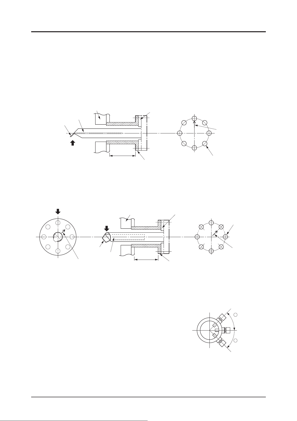
2.2.2 Mounting method of fl ow guide tube
■
■
■
(Designation of type: When 9th to 11th digits are 5A
The fl ange of fl ow tube has mounting holes at 8 locations. These holes are available for regulating an in-
fl ow into the fl ow guide and mounting the tube correctly in the fl owing direction of gas and it is enough if
mounted at 4 locations.
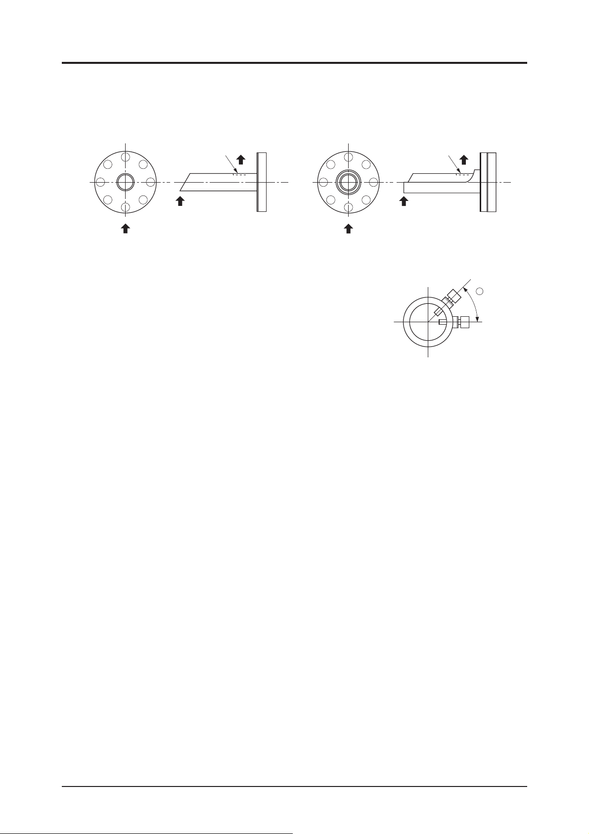
(1) Direction of tongue and Partition plate of fl ow guide tube
1 When exhaust gas temperature is under 200°C and gas fl owing velocity is low
As illustrated below, set the partition plate inside the fl ow guide tube at a right angle to the gas fl ow and
mount the tube so that the tongue turns to an upstream direction relative to the gas fl ow.
■
, 5B
and 5C
■
)
■
Packing (not included
in scope of supply)
Companion flange
(not included in scope of supply)
Arrow mark of
flow guide tube
ø15 (JIS5K-65A)
Partition plate
Tongue
Gas flow
Furnace wall
min.60mm
2 When exhaust gas temperature is 200°C or higher and gas fl owing velocity is fast
As illustrated below, till the partition plate inside the fl ow guide tube 45° to the gas fl ow and mount the
tube so that the tongue turns to a down-steam direction relative to gas fl ow.
Gas flow
Gas flow
Tongue
Partition plate
Arrow mark of flow guide tube
Furnace wall
min.150mm
Packing (not included
in scope of supply)
ø15 (JIS5K-65A)
Arrow mark of
flow guide tube
Companion flange
(not included in scope of supply)
(2) Inserting angle of fl ow guide tube
According to the temperature of exhaust gas and the amount of dust, the inserting angle of the fl ow guide
tube differs. With reference to the following conditions, install a companion fl ange.
1 When exhaust gas temperarture is under 200°C and amount of
dust is under 0.2g/Nm
• Inserting angle: within a range of -45 to +45°
2 When exhaust gas temperature is 200°C or higher and amount of
dust is under 0.2g/Nm
3
3
Up
+
Inserting angle
• Inserting angle: within a range of -20 to +20°
3 When amount of dust is over 0.2g/Nm
• Inserting angle: within a range of 0 to +45°
3
Down
−
Inserting angle
5
Page 11
2.2.3 Mounting method of high dust-use fl ow guide tube
(Desingation of type : When 10th digits are D, E, F, G, J, K)
Mount the tube so that the gas outlet turns downward relative to the gas fl ow as shown below.
For high dust
Gas outlet
Gas flow
Gas flow
Fitted with high dust cover
Gas flow
Be careful not to block the gas outlet by the furnace wall or pipe and
keep the periphery of the outlet widely.
Set the inserting angle within a range of 0 to +45°.
Gas outlet
Gas flow
Up
+
Inserting
angle
Down
6
Page 12
3. PIPING
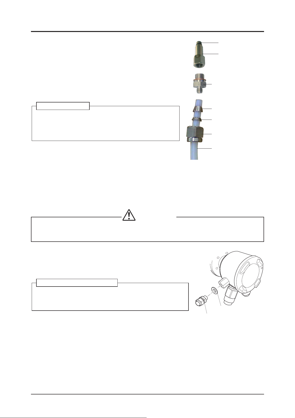
3.1 Piping of calibration gas
As the piping material, use a tefl on-made ø6 mm or ø1/4 inch tube.
• From the coupling attached to the detector, remove 2 nut,
3 front ferrule and 4 back ferrule, put them through the ø6
mm or ø1/4 inch tefl on tube for piping, and then attach it to
coupling.
• For mounting 2 nut, tighten by making about 2 turns with a
spanner after it cannot be turned any more by hand.
Joint for calibration gas:
The joint for calibration gas is a special joint with a built-in
check valve.
If a malfunction occurs, order the joint for calibration gas and
attach it.
3.2 Piping of reference gas inlet
Main body
(calibration gas inlet port)
1 Coupling
5 adapters
3 Frount ferrule
4 Back ferrule
2 Nut
ø6 mm or ø1/4 inch
teflon tube for piping
If the atmosphere around the terminal box is signifi cantly dirty or the humidity of the location is extremely
high, install piping for reference gas.
If the 13th digit of the type is “A” or “B,” the piping for reference gas is delivered together with the detector
body.
CAUTIONS
• When used at an ordinary place (oxygen concentration : 20.6 vol%), the reference gas is unnecessary. So, don’t remove a hexagonal plug of the mounting port of reference gas inlet unnecessarily
since a waterproofness becomes poor.
Refer to the previous section “3.1 Piping to calibration gas” for the
installation method of piping.
Set one of the two reference gas ports as “inlet” and the other as “outlet.”
Install piping so that dust or water does not enter the “outlet.”
Attachment of joints for reference gas:
If you order the joints for reference gas additionally, remove the hexagonal plugs and attach the joints for reference gas (two locations) as shown
in the fi gure on the right.
2 Reference gas inlet
3.3 Piping for blow down air
1 Packing
Connect the blow air inlet (4 locations) of blowdown-fi tted fl ow guide tube by detaching a plug of the upper-
side blow port (1 location) so that drain does not accumulate.
For the blow piping, use a copper tube 15A SGP or larger (tube having larger inside diameter) or ø10/ø8
tefl on tube. And, use L-shape joint or union without bending the pipe wherever possible and keep the piping
length as short as possible.
7
Page 13

3.4 Piping drawing
(1) Flow guide tube system
Rc1/4
(upper side blow port should be selected)
Blow-down, 200 to 300kPa
Flow guide tube
Gas temperature.
600ºC max.
Sample gas outlet
Gas temperature.
600ºC max.
Flow guide tube
for high particulate
Sample gas outlet
Gas temperature.
600ºC max.
Flow guide for high
particulate with cover
RS232C
or
RS485
(option)
Solenoid valve
(not supplied)
15ASGP
tube equivalent
(not supplied)
Detector
(ZFKE)
from (1)
exhaust
AC power
123
6
45
supply
Black
Black
Blue
Yellow
115234567891011121314
+
O2 sensor
input
*4
Red
−
O2
Thermocouple
for combustion
control
+
TC2
White
+
−
TC1
O
2 sensor
thermocouple
input
−
DI1
16
17
AO
+
or
Analog output
4 to 20mA DC
or
0 to 1V DC
Contact input
DI2 DI3
18 19
−
Fault contact
DICOM
20
output
ALARM
Alarm
contact
output
21 22
Blow
contact
output
Maintenance
contact
output
MAINTE
23 24
ZV
ZERO
GAS
Calibrating gas
contact output
Calibrating gas
contact output
COM
25 28
12 3
TM-2
Reduction valve
(unnecessary when supply
air pressure is 200 to 300kPa
15ASGP
tube equivalent
(not supplied)
Converter (ZKME)
TM-1
O2 sensor
heater power input
AC power
SPAN
supply
GAS
AC
L
NSV
26 27
Supply air
*3
PE
φ
6mm or φ1/4 inch tube
for calibration gas
(not supplied)
*2 Ref. gas
Flowmeter
(ZBD4)
(1.5 to 2.0L/min)
Joint
Solenoid valve
(not supplied)
(1) to Detector
φ
6mm or φ1/4 inch tube
for calibration gas
(not supplied)
Note:
*1 Standard gas or instrumentation air can be used in place of span gas.
*2 Instrument quality air or bottled air is available as reference gas instead of ambient air.
*3 Protective earth.
*4 Connect the shield of a exclusive cable with the ground terminal in the converter.
(1.5 to 2.0L/min)
Solenoid valve
(not supplied)
Reduction
valve (ZBD6)
AC power
supply
Standrad gas
for zero point
(ZBM)
Reduction valve
(unnecessary when supply air pressure is 50 to 100kPa)
AC power
supply
*1 Air supply
Reduction vale
(ZBD6)
Span point
*1
Standard gas for
span point (ZBM)
8
Page 14

(2) Flow guide tube system (with valve)
Rc1/4
(upper side blow port should be selected)
Blow-down, 200 to 300kPa
Flow guide tube
Gas temperature.
600ºC max.
Sample gas outlet
Gas temperature.
600ºC max.
Flow guide tube
for high particulate
Sample gas outlet
Gas temperature.
600ºC max.
Flow guide for high
particulate with cover
RS232C
or
RS485
(option)
Solenoid valve
(not supplied)
15ASGP
tube equivalent
(not supplied)
Detector
(ZFKE)
from (1)
exhaust
AC power
123
6
45
supply
Black
Black
Blue
Yellow
115234567891011121314
+
O2 sensor
input
*4
Red
−
O2
Thermocouple
for combustion
control
+
TC2
White
+
−
TC1
O
2 sensor
thermocouple
input
−
DI1
16
17
AO
+
or
Analog output
4 to 20mA DC
or
0 to 1V DC
Contact input
DI2 DI3
18 19
−
Fault contact
DICOM
20
output
ALARM
Alarm
contact
output
21 22
Blow
contact
output
Maintenance
contact
output
MAINTE
23 24
ZV
ZERO
GAS
Calibrating gas
contact output
Calibrating gas
contact output
COM
25 28
12 3
TM-2
Reduction valve
(unnecessary when supply
air pressure is 200 to 300kPa
15ASGP
tube equivalent
(not supplied)
Converter (ZKME)
TM-1
O2 sensor
heater power input
AC power
SPAN
supply
GAS
AC
L
NSV
26 27
Supply air
*3
PE
φ
6mm or φ1/4 inch tube
for calibration gas
(not supplied)
*2 Ref. gas
Flowmeter
(option)
Flowmeter
(ZBD4)
(1.5 to 2.0L/min)
Val ve
(option)
MEASURE
(1) to Detector
φ
6mm or φ1/4 inch tube
for calibration gas
(not supplied)
Note:
*1 Standard gas or instrumentation air can be used in place of span gas.
*2 Instrument quality air or bottled air is available as reference gas instead of ambient air.
*3 Protective earth.
*4 Connect the shield of a exclusive cable with the ground terminal in the converter.
(1.5 to 2.0L/min)
SPAN
ZERO
9
Reduction
valve (ZBD6)
Standrad gas
for zero point
(ZBM)
Reduction vale
(ZBD6)
*1
Standard gas for
span point (ZBM)
Span point
*1 Air supply
AC power
supply
Page 15

(3) Flow guide tube system (with ejector)
Rc1/4
(upper side blow port should be selected)
Blow-down, 200 to 300kPa
Flow guide tube
Gas temperature.
600ºC max.
Calibrating gas
Sample gas outlet
Gas temperature.
600ºC max.
Sample gas outlet
Gas temperature.
600ºC max.
Flow guide for high
particulate with cover
exhaust
Flow guide tube
for high particulate
RS232C
RS485
(option)
or
Solenoid valve
(not supplied)
15ASGP
tube equivalent
(not supplied)
Detector
(ZFKE)
from (1)
exhaust
Flowmeter
(ZBD4)
6
(5 to 10L/min)
123
from (2)
AC power
supply
45
Black
Black
Blue
Yellow
115234567891011121314
+
O2 sensor
*4
Red
−
O2
input
Thermocouple
for combustion
control
+
TC2
White
+
−
TC1
O
2 sensor
thermocouple
input
−
DI1
16
17
AO
+
or
Analog output
4 to 20mA DC
or
0 to 1V DC
Contact input
DI2 DI3
18 19
−
Fault contact
output
ALARM MAINTE
DICOM
20
Alarm
contact
output
21 22
Blow
contact
output
Maintenance
contact
output
23 24
ZV
ZERO
GAS
Calibrating gas
contact output
Calibrating gas
contact output
COM
25 28
12 3
TM-2
Reduction valve
(unnecessary when supply
air pressure is 200 to 300kPa
15ASGP
tube equivalent
(not supplied)
Converter (ZKME)
TM-1
O2 sensor
heater power input
AC power
SPAN
supply
GAS
AC
L
NSV
26 27
Supply air
*3
PE
φ
6mm or φ1/4 inch tube
for calibration gas
(not supplied)
*2 Ref. gas
Flowmeter
(ZBD4)
(1.5 to 2.0L/min)
Joint
(1) to Detector
φ
6mm or φ1/4 inch tube
for calibration gas
(not supplied)
Note:
*1 Standard gas or instrumentation air can be used in place of span gas.
*2 Instrument quality air or bottled air is available as reference gas instead of ambient air.
*3 Protective earth.
*4 Connect the shield of a exclusive cable with the ground terminal in the converter.
(0.2 to 0.5L/min)
Solenoid valve
(not supplied)
Solenoid valve
(not supplied)
(2) to ejector
10
Reduction
valve (ZBD6)
Joint
AC power
supply
Standrad gas
for zero point
(ZBM)
Reduction valve
(unnecessary when supply air pressure is 50 to 100kPa)
AC power
supply
*1 Air supply
Reduction vale
(ZBD6)
Span point
*1
Standard gas for
span point (ZBM)
Page 16

(4) Flow guide tube system (with ejector+valve)
Rc1/4
(upper side blow port should be selected)
Blow-down, 200 to 300kPa
Flow guide tube
Gas temperature.
600ºC max.
Flowmeter
Calibrating gas
Sample gas outlet
Gas temperature.
600ºC max.
Flow guide tube
for high particulate
Sample gas outlet
Gas temperature.
600ºC max.
Flow guide for high
particulate with cover
exhaust
RS232C
(option)
or
RS485
(ZBD4)
(5 to 10L/min)
6
Black
Blue
Yellow
115234567891011121314
+
O2 sensor
input
*4
12 3
TM-2
from (1)
123
Red
−
O2
Thermocouple
for combustion
control
+
TC2
45
Black
White
+
−
TC1
O
2 sensor
thermocouple
input
−
DI1
16
17
from (2)
AO
+
or
Analog output
4 to 20mA DC
or
0 to 1V DC
Contact input
DI2 DI3
18 19
−
Fault contact
output
ALARM MAINTE
DICOM
20
15ASGP
tube equivalent
(not supplied)
Detector
(ZFKE)
exhaust
AC power
supply
Blow
contact
output
Alarm
Maintenance
contact
contact
output
output
21 22
Solenoid valve
(not supplied)
ZV
23 24
ZERO
GAS
Calibrating gas
contact output
Calibrating gas
contact output
O2 sensor
heater power input
SPAN
GAS
COM
26 27
25 28
Reduction valve
(unnecessary when supply
air pressure is 200 to 300kPa
Supply air
15ASGP
tube equivalent
(not supplied)
Converter (ZKME)
TM-1
AC power
supply
AC
NSV
L
*3
PE
Val ve
(option)
MEASURE
φ
6mm or φ1/4 inch tube
for calibration gas
(not supplied)
*2 Ref. gas
Flowmeter
(option)
Flowmeter
(ZBD4)
(1.5 to 2.0L/min)
(1) to Detector
φ
6mm or φ1/4 inch tube
for calibration gas
(not supplied)
Note:
*1 Standard gas or instrumentation air can be used in place of span gas.
*2 Instrument quality air or bottled air is available as reference gas instead of ambient air.
*3 Protective earth.
*4 Connect the shield of a exclusive cable with the ground terminal in the converter.
(0.2 to 0.5L/min)
SPAN
11
ZERO
Reduction
valve (ZBD6)
Standrad gas
for zero point
(ZBM)
Reduction vale
(ZBD6)
*1
Standard gas for
span point (ZBM)
Span point
*1 Air supply
AC power
supply
Page 17

4. WIRING
CAUTIONS
• In the case of the wiring work, be careful not to drop foreign matters including wire chips inside the
product. Otherwise, this might cause a fi re, failure or malfunction.
• Connect a power source compatible with the rating. Connection of a power source not conforming
to the rating may cause a fi re.
• Before proceeding with the wiring work, be sure to turn off the main power supply. Otherwise,
there is a fear of getting an electric shock.
• As the wiring material, use a proper one conforming to the rating of apparatus. The use of a wiring
material which is not bearable to the rating could cause a fi re.
: Make sure to ground (D-class grounding). Take care so that the converter and the detector is the
same electric potential.
PROHIBITION
• Never do the work at a place where the product gets wet with water, such as the rain. Otherwise, an
electric shock or failure may result.
4.1 Before wiring
Put the cables for R thermocouple and element output away from the power cable to take a noise preventive
step.
Use a dedicated cable.
When an exclusive cable is not used, use the following wire rods:
• For heater (2 pcs.) ...............3A or more in rating
• For R thermocouple ............Specifi ed in JIS C1610-1995 (equivalent to RCA-2-G-0.75mm2-S2).
• Recommended wire rod (at 20 ºC)
For wiring of the detector, be sure to use a solderless terminal (for M3).
•
Recommended solderless terminal ............ Solderless terminal prescribed in JIS C 2805 (Nominal designation: R1.25-3)
For heater
Nominal sectional area (mm2) 0.75
Number of composed element wires/
diameter of element wire (mm)
Outside dia. (mm) 1.1 1.14
Thickness of vinyl insulating material (mm) 0.6
Composition
Thickness of vinyl sheath (mm) 1.0 1.5
Max. conductor resistance per unit length (Ω/m) 24.4 —
Test voltage (V) 1000 1500
Insulation resistance per unit length (MΩ•km) 5 40
Rating (A) 7 —
External diameter of sheath (mm)
Element output
compensation conductor
30/0.18
7 to 10
CAUTIONS
•
When you do not use a dedicated cable, make sure to use a cable with the same external diameter as
a sheath which is applicable to a cable gland.
For the reason of protection against injury, install the cable sheathing an appropriate protection equipment,
such as a protection tube of a steel conduit as needed.
In the case of wiring work at the zone 1, take an appropriate prevention countermeasure against gas fl ow to
prevent explosive gas being fl own into the zone 2 or unclassifi ed area through a kind of duct or protection tube.
When connecting 2 cables, and connecting a cable and a cable covered with metal tube for fl ameproof, use a
fl ameproof-structured box.
12
Page 18

4.2 How to open the cover
Loosen the hexagon socket head screw, and open the cover. (use an
attached hexagonal wrench)
4.3 Wiring to each terminal
2 core
wire
Exclusive cable
for converter
4 core
wire
Heater power
100 to 120VAC 50/60Hz
or 200 to 240VAC 50/60Hz
1 Black
2 Black
Thermo couple (R-type)
3 Red
4 White
Sensor output
5 Yellow
6 Blue
Grounding
terminal : M4
5 Yellow
6 Blue
Screw for wiring
connections : M3
Hexagon socket
head screw
1 Black
3 Red
1
2
3
6
4
5
S+
H
T+
6
1
3
S-
H
T-
4 White
2 Black
13
Page 19

Connect the protective grounding to one of the two terminals in the fi gure below. (Class D (Class 3)
grounding, grounding resistance: 100 Ω or less)
Grounding
Grounding
terminal
terminal
5
5
*
*
6
6
• Use the cable more than 0.75mm2 for main ground (earth)
Note
line.
• For solderless terminal, doubly caulk the core and the sheath
5
5
*
*
6
6
Grounding
Grounding
terminal
terminal
separately.
The core should be poked from 0.5 to 1.0 mm.
The core should be so as not to
be seen or not to be come apart.
The crimping (vary by tools)
should clearly be in the
normal place.
No space required between
the insulating material and the wire.
Wiring of grounding terminal
Attach the solderless terminals to
the grounding terminals with them
between the tooth lock washer and
screw with washer.
( recommended tightening torque: 1.8
N·m)
Screw with washer M4
Tooth lock washer
• Use “ ” type of solderless terminal.
Double caulking
14
Page 20

5. OPERATION AND STOP
DANGER
• In case where combustible gas is contained in the measured gas, make sure of the gas composition
and specifi cations carefully before using this product. Otherwise, the original performance is not
displayed and there is a fear of explosion.
• Turn on electricity before closing the cover.
5.1 Start of operation
• When electricity is turned on after completion of wiring and piping work, the detector starts its operation.
• After warm-up at least 10 minutes, start the operation of the furnace.
• After zero calibration and span calibration have fi nished, get to work on the measurement.
• For the method of calibration, refer to each instruction manual of converters (ZKME).
• When the converters (ZKME) are not used, run the zero and span calibration gases and calibrate by converting the output in a stabilized state into oxygen concentration according to the standard output table of
converter in Item. “6.3”.
If using the reference gas, supply it before the calibration. (fl ow rate: 0.2 to 0.5 L/min)
5.2 Stop of operation
If the power is turned on in a state of dew condensation it leads to the failure of detector. Stop the operation
following the procedures described below.
(1) In case of short-term shutdown (about 1 week) of furnace
• Keep the power supply of the detector (converter) turned “ON”. This can prevent the detector from
getting dewed.
Also, note that if “ON-OFF” is repeated in a condition where the detector has dewed (according to the
furnace and ambient conditions), the detector might fail.
• When the ejector is in use, stop the air supply to the ejector.
(2) In case of long-term shutdown of furnace
• Turn off the power of the detector (converter) after the peripheral air of the detector inside the furnace
(especially, temperature and humidity) has become an air environment. Or, turn off the power after
taking the detector out of the furnace and leaving it as it is for 15 minutes or more.
• When the ejector is in use, stop the air supply to the ejector.
15
Page 21

6. MAINTENANCE AND CHECK
CAUTIONS
• Do the work in a condition where the main power supply has been turned off.
If the work is done while current is fl owing, there is a fear of getting an electric shock.
• The operation temperature of the detector (tip of the ceramic heater) is about 800°C and the surface
temperature is also very high. So, never touch it by bare hand. Otherwise, there is a fear of getting a
burn.
• Before proceeding with the cleaning of the fl ow guide tube, turn off the main power and cool the tube
down fully and then, do the work. Otherwise, there is a fear of getting a burn.
• Don’t use other renewal parts than those designated by the maker. Otherwise, the original performance
is not displayed fully and an accident or failure could come about.
• Dispose of the renewal parts including the maintenance parts as an incombustible.
DANGER
• Open the cover 30 minutes after turning the power off. There is a fear of ignition of ambient fl ammable gases by heater's heat.
PROHIBITION
• Never do the work at a place where the product gets wet with water, such as the rain. Otherwise, an
electric shock or failure may result.
6.1 Check
Perform the check periodically for using the product always in good condition. Especially, perform the
checks shown in table below. Moreover, perform the periodic check at a time of checking the furnace or
every 6 months.
Execution of zero & span calibration • When the converters (ZKME) are in use: With reference to the
Check for looseness of cable gland. Retighten the cable gland or if the packing is found deteriorated,
Check of residue in calibration gas cylinder Check it by a primary pressure gauge.
Check of blowdown (when blowdown
nozzle is fi tted)
Check for leak from packing fi tted between
fl ow guide tube and companion fl ange and
O-ring of detector.
Removing detector, check for clogging of
ceramic fi lter of detector.
Check by disconnecting for clogging or
corrosion of fl ow guide tube.
Remove and check if there is not clog in
the lead-in port of the air outlet of ejector.
Periodic check Daily check
Check items Details of checking work
instruction manuals of the converters (ZKME), check once a week
as a rough standard. (calibration gas fl ow rate : 1.5 to 2.0 L/min)
• When the converters (ZKME) are not used: Running the zero and
span calibration gases, make calibration once a week as a rough
standard by converting the output in a stabilized state into oxygen
concentration according to the standard output table of converter in
Item “6.3”.
replace.
Referring to each instruction manual of the converters (ZKME), check
at 200 to 300 kPa.
If either of the packing and O-ring or both of them are found deteriorated, replace with new O-ring (refer to the part No. for procurement
in Item “6.4”) and replace the packing (not included in scope of supply).
When it is necessary to replace the ceramic fi lter, refer to Item “6.2.2”.
Check following the procedure in Item “6.2.3”.
Clean the air outlet and lead-in port.
16
Page 22

6.2 Maintenance
The replacing intervals of sensor unit, ceramic fi lter and packing, and the maintenance periods of fl ow guide
tube and sampling probe differ depending on the working conditions including the components of measured
gas and the amount of dust.
The replacing intervals in a general conditions are shown below. Determine the replacing intervals in the
individual working condition with a period till a fi rst replacement after delivery and operation as a rough
standard.
• Sensor unit ................................................ Yearly
• Filter cap................................................... At 6 month interval
• Flow guide tube ........................................ At 3 to 4 year interval
• Packing ..................................................... Yearly
Please note the followings.
(1) For the fl ameproof type, 3 factors of mechanical strength of detector case, gap, and depth of gap are very
important. Therefore, take care not to scratch on the joint area or screw connection part, or to make an
impact on the case.
(2) If the necessary parts for conservation of fl ameproof (terminal box, screw part of terminal box cover,
joint area, connection between terminal box and fl ange, cable gland, joint for reference gas, etc.)
damaged or corroded, contact us. It is very danger to fi x up them carelessly because change of gap or the
like possibly occurs.
(3) When use them again after repair or mend, check the necessary parts for conservation of fl ameproof
adequately and confi rm that screws have been tighten fi rmly.
Make sure to tighten the cover completely. Do not open the terminal box cover unnecessarily at the site.
Tighten the hexagon socket head screw of the terminal box cover to prevent the cover being opened or
closed unnecessarily at the site. Use the attached hexagonal wrench.
17
Page 23

6.2.1 Replacement of Sensor unit
Caution about the replacement of the sensor unit:
• Check that the sensor unit complies with the specifi cations of the power supply you use.
• Avoid replacing the sensor unit while the current is applied.
• The temperature of the detector becomes high. Replace the sensor unit after the temperature is reduced suffi ciently.
(1) Turn off the power for the detector. (Set the switch of the converter or the main power supply to “OFF”.)
(2) Check that the surface temperature of the detector is reduced suffi ciently.
(3) Remove the hexagon socket head screw for fi xing attached on the terminal box cover (by using the at-
tached wrench).
(4) Remove the six wires connected the terminal block of the sensor unit (M3 screws, six locations).
(5) Remove the ring screws (M3 screws, four locations) fastening the sensor unit .
(6) Remove the sensor unit and o-ring from the detector.
(7) Attach the supplied O-ring of the replacement sensor unit to the groove for the O-ring at the detector.
(8) Attach the replacement sensor unit to the detector.
(Attach the sensor unit so that the rotational direction is as shown in the fi gure below.)
(9) Fasten the sensor unit with the supplied ring pan-head machine screws (M3 screws, four locations).
(recommended tightening torque: 0.7 N·m)
(10) Connect six wires to the terminal block of the sensor unit and attach the terminal block cover.
(11) Attach the terminal box cover.
Groove for the O-ring
O-ring
Detector
2 core
wire
Exclusive cable
for converter
4 core
wire
6.2.2 Replacement of Filter cap
• After turning “OFF” the power of the detector, lower the surface
temperature of the tip (at the Filter cap side) by cooling down fully
with the air.
• After the detector cooled adequately, remove the fi lter cap from the
detector and then remove the spring.
• Attach a fi lter and a new spring to the detector, and then tighten the
cap completely.
Sensor Unit
Pan head screw with
washers (4 pieces)
Heater power
100 to 120V AC 50/60 Hz
or 200 to 240V AC 50/60Hz
1 Black
2 Black
Thermo couple (R-type)
3 Red
4 White
Sensor output
5 Yellow
6 Blue
Grounding
terminal : M4
5 Yellow
6 Blue
Screw for wiring
connections : M3
1 Black
3 Red
1
2
3
6
4
5
S+
H
T+
6
1
3
S-
H
T-
4 White
2 Black
Spring
Filter
6.2.3 Maintenance of fl ow guide tube
18
Page 24

• After removing the fl ow guide tube from the furnace wall and then, from the detector, cool the tube down
fully in the air.
• Remove dust sticking to the outside of the fl ow guide tube by water-washing with the use of a scrubbing
brush.
• Remove dust sticking to the inside of the fl ow guide tube by using a metallic rod or screwdriver.
(Clean so that tube is through at least about 3/4 part of the whole interior.)
• For the fl ow guide tube for high dust, remove together dust sticking around the gas outlet.
6.3 Standard output of detector
For the output voltage of the detector, refer to the standard output table below.
Standard output table (Reference)
Oxygen
concentration
(vol%)
0.01
0.05
0.1
0.5
1.0
1.2
1.4
1.5
1.6
1.8
2.0
2.2
2.4
2.5
2.6
2.8
3.0
3.5
4.0
4.5
5.0
5.5
6.0
6.5
7.0
7.5
Detector output
(mV)
168.15
132.68
117.41
81.94
66.67
62.65
59.25
57.73
56.31
53.71
51.39
49.29
47.37
46.47
45.61
43.98
42.46
39.06
36.12
33.52
31.20
29.10
27.18
25.42
23.79
22.26
Oxygen
concentration
(vol%)
8.0
8.5
9.0
9.5
10.0
11.0
12.0
13.0
14.0
15.0
16.0
17.0
18.0
19.0
20.0
20.6
21.0
22.0
23.0
24.0
25.0
30.0
35.0
40.0
45.0
50.0
Detector output
(mV)
20.84
19.51
18.25
17.06
15.92
13.82
11.91
10.14
8.51
6.99
5.57
4.23
2.97
1.78
0.65
0.00
-0.43
-1.45
-2.43
-3.37
-4.27
-8.29
-11.68
-14.62
-17.22
-19.54
19
Page 25

6.4 Arrangement
No. Description Part No. for procurement
1 Filter cap *ZZPZFKE-TK7N7179C1
2 Spring *ZZPZFKE-TK7N9327P1
3 O-ring for sensor *ZZPZFKE-8552836
4 Joint for calibration gas *ZZPZFKE-TK4J4660C1
*ZZPZFKE-TK7N8173P34
5 Joint for reference gas *ZZPZFKE-TK4J5565C1
6 Adapter for calibration gas joint *ZZPZFKE-TK7N8173P25 For ejector
7 Adapter for calibration gas joint *ZZPZFKE-TK7N8173P1 For ø 6 mm tube
*ZZPZFKE-TK7N8173P3 (Packing)
8 Adapter for calibration gas joint *ZZPZFKE-TK7N8173P2 For ø1/4 inch tube
*ZZPZFKE-TK7N8173P3 (Packing)
9 Adapter *ZZPZFKE-TK7K1652P9 For ø6 mm tube
*ZZPZFKE-TK7J0987P2 (Packing)
10 Adapter *ZZPZFKE-TK7K1652P10 For ø1/4 inch tube
*ZZPZFKE-TK7J0987P2
11 Ejector *ZZPZFKE-TK7P0738C1
12 Cable gland
13 Filter for high particulate
14 Flow guide tube According to the following table “Drawing
13. Filter for high
particulate
*ZZPZFKE-TK7N7181P2
*ZZPZFKE-TK7P0524C1
No. for fl ow guide”
1. Filter cap
(Procured type)
(Packing)
4. Joint for calibration gas
5. Joint for reference gas
Remark
9, 10. Adapter
2. Spring
9, 10. Adapter
11. Ej ect or
3. O-ring for sensor
12. Cable gland
6, 7, 8. Adapter for calibration
gas joint
20
Page 26

Part No. for procurement of fl ow guide
Drawing No. for flow guide
*ZZP-TK7P0526C
Digit of type
Flange size
JIS 5K 65A 01
JIS 5K 80A 02
JIS 5K 100A 03
JIS 10K 65A 04
JIS 10K 80A 05
JIS 10K 100A 06
ANSI 150LB 2B 07
ANSI 150LB 3B 08
ANSI 150LB 4B 09
DIN DN50 PN10 10
DIN DN80 PN10 11
Purpose/Material
For general explosion-proof/SUS316 1
With blowdown nosle/SUS316 2
For high particulate/SUS316 3
With cover for high particulate/SUS316 4
For high particulate/SUS310S 5
With cover for high particulate/SUS310S 6
For high particulate/Titanium 7
With cover for high particulate/Titanium 8
specification
9th digit
7
8
9
A
B
C
D
E
F
G
H
Digit of type
specification
10th digit
F
G
H
J
K
L
M
N
Code for flange
combination
Code for
purpose
combination
300
500
750
1000
Insertion length
Digit of type
specification
11th digit
3
5
7
1
Code for
insertion length
combination
1
2
3
4
21
Page 27

7. TROUBLESHOOTING
CAUTIONS
• If a failure should occur which cannot be judged even if referring to the operation manual, be sure to
ask the nearest dealer or Fuji adjustment serviceman for repair. If disassembled carelessly, there is a
fear of an accident or injury.
Troubles Probable causes Check procedures (normal values) Remedies
• Indication is fi xed.
• Indication response
is slow.
• Temperature alarm
continues coming on
despite 20 minutes
having elapsed after
turning on power.
• Indication is too high
or too low.
• Clogging of ceramic fi lter
of detector and fl ow guide
tube interior
•
Leak from joint and airtightness of mounted part.
• Deterioration of detector • Check by changing zero calibra-
• Decrease of exhaust gas
fl owing velocity
• Disconnection of cable • Check continuity. • Replace cable.
• Error in wiring • Check wiring. • Wire correctly.
• Low supply voltage • Check if supply power is as
• Disconnection of thermocouple
• Blow out of fuse of converters (ZKME)
• Disconnection of detector
heater
• Looseness of fl ange
mounted part or defects
of O-ring or packing (not
included in scope of supply).
• Deterioration of detector • Check airtightness of calibration
• Abnormality of detector
temperature
• Change of ambient air
oxygen concentration of a
terminal box or very high
humidity
• Check visually for fouling of ceramic fi lter of detector and clog-
ging of fl ow guide tube interior
with dust.
• Check for looseness of each joint
and airtightness of mounted part.
tion gas over to span calibration
gas and vice versa if it takes
more than 5 minutes for 90%
response.
• Check exhaust gas responding
time after stop of calibration gas
supply.
specifi ed.
• Check continuity.
• Check if resistance across terminals No. 3 and No. 4 is 2 to 3 Ω.
• Check continuity of fuse. • Exchange fuse(s).
• Check heater resistance as follows (exclusive of wiring resistance):
For 100V : 50 to 55 Ω
For 200V : 240 to 260
• Check airtightness of detection
unit, fl ow guide tube and fl ange
mounted part.
• Check for leak in from periphery. • Shield
gas supply port.
• Check at a time of running zero
and span calibration gases if
detector output (mV) is higher
or lower than others. (Refer to
Table in Item “6.3”).
• Check indicated temperature of
converter.
• Check ambient air oxygen concentration of a terminal box is
20.6 vol%.
Ω
• Clean or exchange ceramic fi lter, if need be.
•
Retighten and replace
joint(s), if need be.
• Replace detector.
• Increase amount of
exhaust gas inside fl ow
guide tube to be taken in.
• Clean fl ow guide tube.
•
Supply correct power.
• Replace detector.
(Refer to each instruction
manual of conver-ters)
(ZKME).
• Replace detector.
• Retighten mounting
screw.
• Exchange O-ring.
• Exchange packing
(not included in scope of
supply
•
Retighten calibration
gas joint.
• Replace detector.
• Use reference gas inlet.
22
Page 28

8. APPENDIX
8.1 Specifi cation
8.1.1 General Specifi cations
• Measuring object: Oxygen in noncombustible gas
• Measuring method: Directly insert type zirconia system
• Measuring range: 0 to 2 ··· 0 to 50 vol% O
2 ranges available in 1 vol% O2 steps
• Repeatability: Within ±0.5 %FS
• Linearity: Within ±2 %FS
• Response time: Within 4 to 7 sec, for 90% (from calibration
gas inlet)
• Warmup time: approx. 10 min
• Analog output: 4 to 20 mA DC (allowable load resistance less
than 500Ω) or 0 to 1 V DC (output resistance
more tha n 100 Ω)
• Power supply: Rated voltage;
100 to 120 V AC (operating voltage 90 to
132 V AC)
200 to 240 V AC (operating voltage 190 to
264V AC)
Rated frequency; 50/60 Hz
• Power consumption: Maximum 240 VA (Detector: approx. 200 VA,
Converter: approx. 40 VA)
Normal 70 VA (Detector: approx. 50 VA,
Converter: approx. 20 VA
8.1.2 Detector Specifi cations (ZFKE)
• Measured gas temperature:
Flow guide tube system; −10 to +600ºC (for
general-use, corrosive gas)
• Measured gas pressure:
−3 to +3 kPa (−306 to +306 mm H
• Flow guide tube: With or without blow-down nozzle
Flange; JIS5K 65A FF
(JIS5K-80AFF for high particulate gas)
Insertion length; 0.3, 0.5, 0.75, 1 m
Other: See. Code Symbols
• Ejector (general-use):
Probe for vacumming up measured gas to
detector (option)
• Operating temperature:
−10 to +60ºC for Primary detecting element
125ºC or less at detector fl ange surface with
power applied
• Storage temperature:
Sensing element: −20 to +70ºC
• Structure: Dust/rain-proof structure (IEC IP66 equivalent)
• Flame proof: See Table 1.
• Filter: SUS316 (fi ltering accuracy 60 μm)
• Main materials of gas-contacting parts:
Detector; Zirconia, SUS316, platinum
Flow guide tube; SUS316
• Calibration gas inlet:
6 mm tube join or ø1/4-inch tube join (as
ø
specifi ed)
• Reference gas inlet (option):
6 mm tube join or ø1/4-inch tube join (as
ø
specifi ed)
• Detector mounting: Horizontal plane ±45º, ambient surrounding
air should be clean.
2
O)
2
• Outer dimensions: (L × max. dia.) 215 mm × 164 mm (detector)
• Mass (approx.) {weight}:
• Finish color: Case: Silver and SUS metallic color
• Ejector air inlet fl ow rate:
• Calibration gas fl ow:
• Blowdown air inlet pressure:
Table 1
TIIS
pending
(
NEPSI EExd IIC T5 Ex II2G
)
Detector; 3.0 kg
Flow guide tube (for corrosive gas, 1 m); 6 kg
Cover: Blue
5 to 10 L/min
1.5 to 2 L/min
200 to 300 kPa {2 to 3 kgf/cm
Detector
Exd IIB T4
2
}
8.1.3 Converter specifi cation (ZKME)
• Concentration value indication:
Digital indication in 4 digits
• Contact output signal:
(1) Contact specifi cation; 6 points, 1a 250 V AC/3A or 30 V DC/3 A
(2) Contact function;
• Under maintenance
• Under blowdown Note3)
• Span calibrating gas
• Zero calibration gas
• Instrument anomalies Note1)
• Alarm Note2)
Note1) The following Instrument errors (1) Thermocouples
break (2) Sensor break (3) Temperature fault
(4) Calibration fault (5) Zero/span adjustment fault
(6) Output error turn the contact-ON
Note2) Alarm selects just one as mentioned below (1) High
(2) Low (3) Upper and Lower (4) High-high
(5) Low-low, it turns ON while operating.
Note3) Under blow down is available in case of option, and it
turns ON while operating.
• Contact input signal:
(1) Contact specifi cation; 3points (the following option)
ON; 0 V (10 mA or less), OFF; 5 V
(2) Contact function;
• External hold
• Calculation reset
• Heater OFF
• Blow down (option)
• Inhibition of calibration
• Calibration start
• Range changee
• Calibration method:
(a) Manual calibration with key operation
(b) Auto. calibration (option)
Calibration cycle; 00 day 00 hour to
99 days 23 hours
(c) All calibration
23
Page 29

•
Calibration gas: • Range settings
Zero gas; 0.010 to 25.00 % O
Span gas: 0.010 to 50.00 % O
• Recommended calibration gas concen-tration
Zero gas; 0.25 to 2.0 % O
Span gas; 20.6 to 21.0 % O
2
2
2
2
(oxygen concentration in the air)
• Blowdown : A function for blowing out with compressed
(option)
air dust that has deposited in the fl ow guide
tube. Blowdown can be performed for a
predetermined time and at predetermined
intervals.
Blowdown cycle; 00 hour 00 minute to
99 hours 59 minutes
Blowdown time; 0 minute 00 second to
0 minutes 999 seconds
• Output signal hold: Output signal is held during calibration,
processing recoverable sensor,processing diagnosis of sensor, warm-up, PID auto tuning,
under set up maintenance mode " available"
and blowdown. The hold function can also be
released.
• Valve and fl ow meter (option):
Selects zero or span gas during manual zero or
span calibration.
• Communication function:
RS232C (MODBUS) standard specifi cation
RS485 (MODBUS) (option)
• Combustion effi ciency display (option):
When you select this display, "rich mode
display" will be an simultaneous display.
This function calculates and displays combustion effi ciency from oxygen concentration and
measured gas temperature.
Thermocouple (R) is required for temperature
measurement.
• Operating temperature:
−20 to +55ºC
• Operating humidity:
95% RH or less, non condensing
• Storage temperature:
−30 to +70ºC
• Storage humidity: 95% RH or less, non condensing
• Construction: Dust-proof, rainproof construction
(corresponding to IP65)
• Explosion proof: See Table 2
• Material: Aluminum case
• Outer dimensions (H x W x D):
470 X 326 X 211 mm (IP65)
• Mass {weight}: IP65: Approx.22 kg (excluding cable and
detector)
• Finish color: Case: Silver
Cover: blue
• Mounting method: Mounted fl ush on panel
Table 2
Converter
TIIS
(pending)
Exd IIB T6
NEPSI EExd IIC T6 Ex II2G
Electrical Safety:
Overvoltage category
; II power supply input
; I relay interfaces
(IEC1010-1)
External overcurrent protective device
; 10A
Equipment interfaces are safety
separated (SELV)
ZFKE, ZKME
24
Page 30

8.2 Designation of type (code table)
8.2.1 Detector
14 151691011121343215678
17
5- -KREFZ
Y
1
2
A
B
1
3
Y
0
Y
0
7
8
9
A
B
C
D
E
F
G
H
F
G
H
J
K
L
M
N
3
5
7
1
1
Cal. gas inlet
Non (G3/8 female screw)
For F6mm tube
For F1/4 inch tube
Ejector for F6mm tube
Ejector for F1/4 inch tube
Power supply
100 to 120VAC 50/60Hz
200 to 240VAC 50/60Hz
Flow guide tube
None
<Flange size>
JIS 5K 65A
JIS 5K 80A
JIS 5K100A
JIS 10K 65A
JIS 10K 80A
JIS 10K 100A
ANSI 150LB 2B
ANSI 150LB 3B
ANSI 150LB 4B
DIN DN50 PN10
DIN DN80 PN10
<Application / meterial>
For corrosive gas / SUS316
With blow-down nozzle / SUS316
For high particular / SUS316
For high particular with cover / SUS316
For high particular / SUS310S
For high particular with cover / SUS310S
For high particular / titanium
For high particular with cover / titanium
<Length>
300mm
500mm
750mm
1000mm
Y
A
B
5
7
C
Reference gas inlet
Non (G1/8 female screw)
for F6mm tube
For F1/4 inch tube
Filter
Standard
For high particular
Instruction manual language
J
Japanese
E
English
Chinese
Specification name plate
1
Standard
Ex. Standard
N
NEPSI
T
TIIS (pending)
Description
8.2.2 Replacement Detector element
Power supply Code symbols
100 to 120V AC ZFK8YY15-0Y0YY-0YY
200 to 240V AC ZFK8YY35-0Y0YY-0YY
25
Page 31

8.2.3 Converter
910111221 345678
E
-11MKZ
1
B
E
1
2
Y
1
2
3
4
5
6
7
13
14
-
Output signal
4 to 20mA DC
0 to 1V DC
Communication function
RS-232C
RS-485
Optional Functions
None
Combustion efficiency display function Note1)
Blowdown
Auto calibration
Combustion efficiency indication
+ Blowdown Note1)
Combustion efficiency indication
+ Auto calibration Note1)
Blowdown + Auto calibration
Combustion efficiency indication + Blowdown
+ Auto calibration Note1)
J
E
C
Y
1
2
1
Note1) When you select this display, rich mode
Instruction manual language
Japanese
English
Chinese
Mounting Option
None (Mounting on panel surface)
With valve
With valve + flowmeter
Specification name plate
Standard
Number of Cable Gland
3
3
4
4
5
5
6
6
7
7
Ex Standard
N
NEPSI
T
TIIS (pending)
will be a simultaneous display.
Description
8.2.4 Exclusive-special cable
921 345678
-1ERZRZ
E
R
YA
YB
YC
YD
YE
YF
YG
YH
YJ
YK
YL
YM
Connectable devices
For Z KME
Types
For R thermocouple
Cable length
6m
10m
15m
20m
30m
40m
50m
60m
70m
80m
90m
100m
Cable end treatment
0
None
1
One side (detector side)
2
Both sides
Description
26
Page 32

8.3 DEVICE CONFIGURATION
The device to be combined differ according to the conditions of the gas to be measured. Select the devices to be
combined with reference to the following table.
Measured gas Device confi guration
Application Temperature Gas Flow DUST Note Detector type Converter type
General-use
(boiler)
For corrosive
gas (refuse
incinerator)
Note (1) Dust volume is approximate value.
(2) Instrument quality air or bottled air is available as reference air by selecting detector with reference air
600ºC or less 5 to 20 m/s Less than 0.2 g/Nm3Fuel; gas, oil ZFKER 5- F Y - ZKME
Less than 10 g/Nm
600ºC or less 5 to 20 m/s Less than 1 g/Nm
Less than 10 g/Nm
Less than 25 g/Nm
Less than 25 g/Nm
3
Fuel: coal
with blow down
3
Included low moisture ZFKER 5- F Y - ZKME
3
Included low moisture
with blow down
3
Included low moisture
with blow down
3
Included high moisture
with blow down
ZFKER 5- G Y - ZKME
ZFKER 5- G Y - ZKME
H
ZFKER 5- K Y -
M
J
ZFKER 5- L Y -
N
ZKME
ZKME
inlet.
27
Page 33

8.4 OUTLINE DIAGRAM (Unit:mm)
(1) Detector (ZFKER: 6th dight code. Y, 1, 2)
Approx. 215
17.5
77
P
View B
Filter
Approx. 126
Approx. 162
32
Approx.
Calibration gas inlet (To order)
SUS316, for φ6mm tube
(the 6th digit is “1”)
Or 1/4 inch tube
(the 6th digit is “2”)
(Not provided if the 6th digit is “Y”)
67
6-
φ
6
φ
Ref. gas inlet (to order)
SUS316, for
(the 13th digit is “A”)
or 1/4 inch tube
(the 13th digit is “B”)
100
φ
φ
6mm tube
Approx.
Exclusive Cable gland
(For power supply)
Exclusive Cable gland
(For signal)
Approx.
(13th digt code A, B)
VIEW A VIEW B
180
Approx. 152
Approx.
140
Approx. 242
(14th digt code 7)
Lock screw M6
External ground
terminal M4
Explotion-proof
name plate
View A
VIEW FROM P
(2) Sensor unit (ZFK8YY)
17.5)
φ
(
(132.7)
(88.4) 3.5
EXTERNAL
CONNECTION DIAGRAM
Heater
Thermocouple
1
2
Black
3
Red White
2-core wire 4-core wire
Exclusive-special cable
20
4-φ3.5(Mount for detector)
φ
35
40
madeinjapan
Element output
45 6
Yellow BlueBlack
T+
S+
H
6
1
3
4
2
5
H
T-
S-
TK4J4664R0
45°
45°
28
Page 34

(3) Detector (ZFKER: 6th dight code. A, B)
P
View B
Filter
Calibration gas inlet
SUS316, for φ6mm tube
(the 6th digit is “A.”)
1/4 inch tube (the 6th digit is “B.”)
Ejector gas outlet
SUS316, for φ6mm tube
(the 6th digit is “A.”)
1/4 inch tube (the 6th digit is “B.”)
Approx. 185
6-
φ
126
Approx.
Approx. 57
6
Ref. gas inlet (to order)
SUS316, for
Or 1/4inch tube (the 13th digit is “B”)
Approx. 215
17.5
77
Calibration
Air out
Approx. 47
Air in
Approx. 37
Approx. 78
φ
6mm tube (the 13th digit is “A”)
Approx. 100
Exclusive Cable gland
(For power supply)
Approx. 21
67
φ
Exclusive Cable gland
Ejector gas inlet
SUS316, for φ6mm tube
(the 6th digit is “A.”)
1/4 inch tube (the 6th digit is “B.”)
(For signal)
Approx.
155
Approx. 140
Approx. 180
(13th digt code A, B)
(14th digt code 7)
VIEW A VIEW B
External ground
terminal M4
Explotion-proof
name plate
Approx. 242
Lock screw M6
View A
VIEW FROM P
EXTERNAL
CONNECTION DIAGRAM
Heater
Thermocouple
1
2-core wire 4-core wire
Exclusive-special cable
2
Black
3
Red White
Element output
45 6
Yellow BlueBlack
29
Page 35

(4) Flow guide tube (for high particulate) (ZFKE: 10th dight code. H, K, M)s)
D
C
67
f
Approx. L
60.5
Gas inlet
t
Approx. 20
6-M5
detector side
Gas outlet
ZFKE MTG. position
Code 11th
L (m)
Mass
Approx.(kg)
3
571
0.5 0.75 1.0
0.3
3.8
3.0
4.8
5.7
L=
(to order)
Z
Blow down
air inlet
Flange size
JIS 5K 65A
JIS 5K 80A
JIS 5K 100A
JIS 10K 65A
JIS 10K 80A
JIS 10K 100A
ANSI 150LB 2B
ANSI 150LB 3B
ANSI 150LB 4B
DIN DN50 PN10
DIN DN80 PN10
N– h
MTG. holes
4-Rc1/4
with plug int.thd.
Code
9th
7
8
9
A
B
C
D
E
F
G
H
DCt f Nh
155
130
180
145
200
165
175
140
185
150
210
175
150
120.7
190
152.4
230
190.5
165
125
200
160
(5) Flow guide tube (for high particulate) (ZFKE: 10th dight code. H, K, M)
4 - Rc 1/4
with plug int thd.
D
C
Blow down air inlet
Select an upper port to
avoid the condensation
in the piping
N - h
MTG. hole
67
38.5
14
14
16
18
18
18
17.5
22.3
22.3
18
20
2
110
2
121
2
141
2
116
2
126
2
151
2
92.1
2
127
2
157.2
0
0
0
0
15
4
19
4
19
8
19
4
19
8
19
8
19.1
4
19.1
4
19.1
8
18
4
18
4
ZFKE MTG.
position
Packing
Gas flow
Gas
outlet
t
3
Code 11th
188
L
50
L (m)
Mass
Approx.(kg)
0.3
4.5
57
0.5 0.75 1.0
5.6
1
Z
L=
(to order)
8.3
7.0
30
Flange size
JIS 5K 65A
JIS 5K 80A
JIS 5K 100A
JIS 10K 65A
JIS 10K 80A
JIS 10K 100A
ANSI 150LB 2B
ANSI 150LB 3B
ANSI 150LB 4B
DIN DN50 PN10
DIN DN80 PN10
Code
9th
7
8
9
A
B
C
D
E
F
G
H
DCt f Nh
155
180
200
175
185
210
150
190
230
165
200
130
145
165
140
150
175
120.7
152.4
190.5
125
160
14
14
16
18
18
18
17.5
22.3
22.3
18
20
2
110
2
121
2
141
2
116
2
126
2
151
2
92.1
2
127
2
157.2
0
0
0
0
15
4
19
4
19
8
19
4
19
8
19
8
19.1
4
19.1
4
19.1
8
18
4
18
4
30
Page 36

(6) Flow guide tube (for high particulate with cover) (ZFKE: 10th dight code. J, L, N)
4 - Rc 1/4
with plug int thd.
ZFKE MTG. position
D
C
Blow down air inlet
Select an upper port to
avoid the condensation
in the piping
N - h
MTG. hole
67
38.5
t
Packing
Gas
outlet
L
(L-10)
Gas flow
Production
(38)
tube
(7) Flow guide tube (ZFKE: 10th dight code. F)
Gas outlet
3
0.3
3.3
Approx.
40
57
0.5
0.75
6.1
4.5
t
ZFKE MTG. position
f
60.5
Approx. L
Gas inlet
Code 11th
L (m)
MASS
Approx.(kg)
(178)
6-M5
detector side
Z
1
1.0
L=
(to order)
7.6
50
30
D
C
67
N- h
MTG. holes
Code 11th
L (m)
Mass
Approx.(kg)
3
0.3
7.1
57
0.5 0.75 1.0
9.0
13.6
11. 4
1
Z
L=
(to order)
Flange size
JIS 5K 65A
JIS 5K 80A
JIS 5K 100A
JIS 10K 65A
JIS 10K 80A
JIS 10K 100A
ANSI 150LB 2B
ANSI 150LB 3B
ANSI 150LB 4B
DIN DN50 PN10
DIN DN80 PN10
31
Code
9th
7
8
9
A
B
C
D
E
F
G
H
DCt f Nh
155
180
200
175
185
210
150
190
230
165
200
130
145
165
140
150
175
120.7
152.4
190.5
125
160
14
14
16
18
18
18
17.5
22.3
22.3
18
20
2
110
2
121
2
141
2
116
2
126
2
151
2
92.1
2
127
2
157.2
0
0
0
0
15
4
19
4
19
8
19
4
19
8
19
8
19.1
4
19.1
4
19.1
8
18
4
18
4
Page 37

International Sales Div.1
Sales Group
Gate City Ohsaki, East Tower, 11-2, Osaki 1-chome,
Shinagawa-ku, Tokyo 141-0032, Japan
http://www.fesys.co.jp/eng
Phone: 81-3-5435-7280, 7281 Fax: 81-3-5435-7425
http://www.fic-net.jp/eng
 Loading...