

Page 1
IN-SITU
ZIRCONIA OXYGEN ANALYZER
DATA SHEET
This oxygen analyzer is used to continuously measure
oxygen concentration in combustion exhaust gas of industrial
boilers or furnaces, and is ideally suited for combustion management and control.
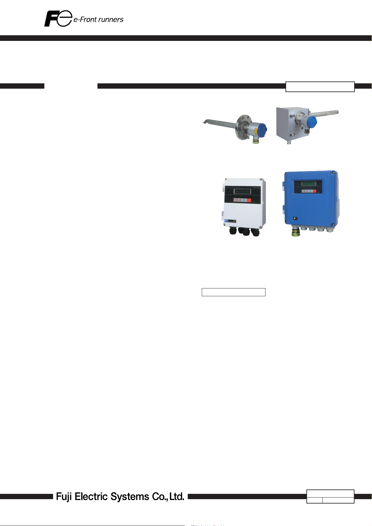
The analyzer system is comprised of the detector and converter coupled together as a complete system. Detector setting confi guration includes the detector fl ow guide tube and
detector sensor. The fl ow guide tube is inserted directly into
the gas and directs gas to the sensor for measurement. The
converter (ZKM) is comprised of the signal processor, input/
output and communications, display and system controls.
The converter is equipped with advanced functionality
such as performing the sensor diagnostics and sensor recovery function, so the detector can be used within long term
stability.
FEATURES
1. Gas sampling device is unnecessary
For quick response, insert the detector directly into the
fl ue Gas sampling functions such as a gas aspirator and a
dehumidifi er are not required.
2. Easy maintenance
The sensor equipped with the detector, has unit construc-
tion, it is easy to replace.
By separating the detector and the fl ow guide tube, fi lter
replacement is easy.
3. More reliable than sensor diagnosis, sensor recoverable function
Depending on the concentration of the measurement gas,
the power of the sensor might deteriorate. The equipment
includes sensor recovery function electronically, checking
the deterioration status of the sensor depletion.
Therefore, it has high reliability and long-lasting stability.
4. Safe and secure
System detects thermocouple break for heater control on
the sensor side. Safety functions of isolating power supply
to the detector or isolating power via external contact input
are also.
5. Easy operation
The operation and setting for the converter can be per-
formed interactively, and available as English, Japanese or
Chinese for language display.
ZFK8, ZKM, ZTA
General-use detector
(ZFK8)
<IP66>
Converter (ZKM1)
High-temperature detector
(ZTA)
<IP67>
Converter (ZKM2)
SPECIFICATIONS
General Specifi cations
Measuring object: Oxygen in noncombustible gas
Measuring method:
Directly insert type zirconia system
Measuring range: 0 to 2 ··· setting range at option 2 in 50
vol% O
2
(in 1 vol% O2 steps)
Repeatability: Within ±0.5%FS
Linearity: Within ±2%FS
Response time: Within 4 to 7 sec, for 90% (from calibra-
tion gas inlet)
Warmup time: More than 10 min
Analog output: 4 to 20mA DC (allowable load resistance
less than 500Ω) or 0 to 1V DC (output
resistance more than 100Ω)
Power supply: Rated voltage;
100 to 120V AC (operating voltage 90
to 132V AC)
200 to 240V AC (operating voltage
190 to 264V AC)
Rated frequency; 50/60Hz
Power consumption:
Maximum 240VA (Detector: approx.
200VA, Converter: approx. 40VA)
Normal 70VA (Detector: approx. 50VA,
Converter: approx. 20VA)
EDSX3-137c
Date
May. 20, 2009
Page 2

ZFK8, ZKM, ZTA
Detector Specifi cations (ZFK)
Measured gas temperature:
Flow guide tube system; −20 to +600ºC
(for general-use, corrosive gas)
Ejector system; −20 to +1500ºC (for
high-temperature gas)
−20 to +800ºC (for general-use)
Measured gas pressure:
−3 to +3kPa (−306 to +306mmH
Flow guide tube: With or without blow-down nozzle
Flange; JIS5K 65A FF
(JIS5K-80AFF for high particulate gas)
Insertion length; 0.3, 0.5, 0.75, 1m
Ejector (general-use):
Probe for guiding measured gas to
detector
Flange; JIS10K 65A RF
Insertion length; 0.5, 0.75, 1, 1.5m (ac-
cording to customer's specifi cation)
Operating temperature:
−10 to +60ºC for Primary detecting ele-
ment
−5 to +100ºC for ejector section
125ºC or less at detector fl ange surface
with power applied
Storage temperature:
Sensing element: −20 to +70ºC
Ejector: −10 to +100ºC
Structure: Dust/rain-proof structure(IEC IP66
equivalent)
Filter: Alumina(fi ltering accuracy 50µm) and
quartz paper
Main materials of gas-contacting parts:
Detector; Zirconia, SUS316, platinum
Flow guide tube; SUS304 or SUS316
Ejector (general use); SUS316, SUS304
Ejector; (for high temperature) SiC,
SUS316, SUS304
Calibration gas inlet:
φ6mm tube join, φ1/4-inch tube join, or
ball valbe (as specifi ed)
Reference air inlet (option):
φ6mm tube join or φ1/4-inch tube join (as
specifi ed)
Detector mounting:
Horizontal plane ±45º, ambient sur-
rounding air should be clean.
Outer dimensions: (L × max. dia.) 210mm × 100mm (de-
tector)
Mass (approx.) {weight}:
Detector; 1.6kg
Ejector; 15kg (insertion length 1m)
Flow guide tube (general-use, 1m); 5kg
Finish color: Silver and SUS metallic color
Ejector air inlet fl ow rate:
5 to 10 L/min
Calibration gas fl ow:
1.5 to 2 L/min
Blowdown air inlet pressure:
200 to 300kPa {2 to 3 kgf/cm
2
}
Ejector exhaust gas processing:
Into furnace, returned to fl ue
Heater temperature drop alarm output (ejector):
Alarm output when below 100
ºC Me-
chanical thermostat
2
N.O. (1a) contact, 200V AC, 2A
Converter specifi cation (ZKM)
Concentration value indication:
Digital indication in 4 digits
Contact output signal:
(1) Contact specifi cation; 6 points, 1a 250V AC/3A or 30V DC/3A
(2) Contact function;
• Under maintenance
O)
2
• Under blowdown Note3)
• Span calibration gas valve
• Zero calibration gas valve
• Instrument anomalies Note1)
• Alarm Note2)
Note1) The following Instrument errors (1) Thermocou-
ples break (2) Sensor break (3) Temperature fault
(4) Calibration fault (5) Zero/span adjustment fault
(6) Output error turn the contact-ON
Note2) Alarm selects just one as mentioned below (1)
High (2) Low (3) Upper and Lower (4) High-high
(5) Low-low, it turns ON while operating.
Note3) Under blow down is available in case of option,
and it turns ON while operating.
Contact input signal:
(1) Contact specifi cation; 3points (the following option)
ON; 0V (10mA or less), OFF; 5V
(2) Contact function;
• External hold
• Calculation reset
• Heater OFF
• Blow down (option)
• Inhibition of calibration
• Calibration start
• Range change
Calibration method:
(a) Manual calibration with key operation
(b) Auto. calibration (option)
Calibration cycle; 00 day 00 hour to
99 days 23 hours
(c) All calibration
Calibration gas: • Available range settings
Zero gas; 0.010 to 25.00% O
Span gas: 0.010 to 50.00% O
2
2
• Recommended calibration gas concentration
Zero gas; 0.25 to 2.0% O
Span gas; 20.6 to 21.0% O
2
2
(oxygen concentration in the air)
Blowdown: A function for blowing out with com-
pressed air dust that has deposited in
the fl ow guide tube. Blowdown can be
performed for a predetermined time and
(option)
at predetermined intervals.
Blowdown cycle; 00 hour 00 minute to
99 hours 59 minutes
Blowdown time; 0 minute 00 second
to 0 minutes 999
seconds
Output signal hold:
Output signal is held during calibration,
processing recoverable sensor, processing diagnosis of sensor, warm-up, PID
auto tuning, under set up maintenance
mode "available" and blowdown. The
hold function can also be released.
Page 3
Valve and Flow meter (option):
Selects zero or span gas during manual
zero or span calibration. Mounted on the
side of the converter.
Communication function:
RS232C (MODBUS) standard specifi cation
RS485 (MODBUS) (option)
Combustion effi ciency display (option):
When you select this display, "rich mode
display" will be simultaneously displayed.
This function calculates and displays
combustion effi ciency from oxygen
concentration and measured gas temperature.
Thermocouple (R) is required for tem-
perature measurement.
Operating temperature:
−20 to +55ºC
Operating humidity:
95% RH or less, non condensing
Storage temperature:
−30 to +70ºC
Storage humidity: 95% RH or less, non condensing
Construction: Dust-proof, rainproof construction
(corresponding to IP66 or IP67 of IEC)
Material: Aluminum case
Outer dimensions (H x W x D):
170 X 159 X 70mm (IP66, Bench type)
220 X 230 X 95mm (IP67)
182 X 163.5 X 70.6mm (Bench type)
Mass {weight}: IP66: Approx. 2kg (excluding cable and
detector)
IP67: Approx. 4.5kg (excluding cable and
detector)
Finish color: IP66: Case: Silver
Cover: Pantone Cool Gray 1C-F
IP67: Munsell 6PB 3.5/10.5 (blue)
Cover: Silver (case)
Mounting method: Mounted fl ush on panel or on pipe
Electrical Safety:
Overvoltage category
; II power supply input
; I relay interfaces
(IEC1010-1)
External overcurrent protective device
; 10A
Equipment interfaces are safety
separated (SELV)
The product conforms to the requirements of the
Electromagnetic compatibility Directive 89/336/EEC
as detailed within the technical construction file
number TZ734575. The applicable standards used to
demonstrate compliance are :
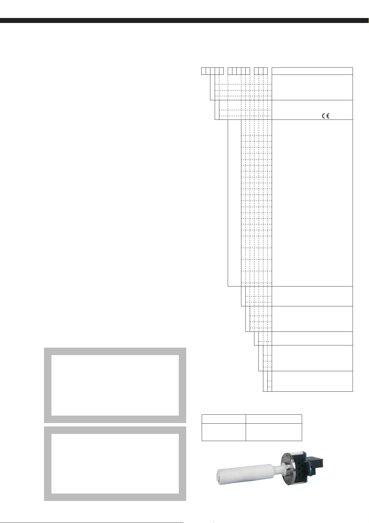
CODE SYMBOLS
(Detector)
14 15 1691011121345678
51R8- -ZFK
1
2
3
1
3
0 Y 0
5 A 3
5 A 5
5 A 7
5 A 1
5 B 3
5 B 5
5 B 7
5 B 1
5 C 3
5 C 5
5 C 7
5 C 1
6 D 3
6 D 5
6 D 7
6 D 1
6 E 3
6 E 5
6 E 7
6 E 1
Z Z Z
Y
A
Y
A
B
(Replacement Detector element)
Power supply Code symbols
100 to 120V AC ZFK8YY15-0Y0YY-0YY
200 to 240V AC ZFK8YY35-0Y0YY-0YY
Cal. gas inlet
For φ6mm tube (SUS)
For φ1/4 inch tube (SUS)
Ball valve
Power supply
100 to 120VAC 50/60Hz
200 to 240VAC 50/60Hz
Flow guide tube
flange application length
None
SUS304 general use 300mm
SUS304 general use 500mm
SUS304 general use 750mm
SUS304 general use 1000mm
SUS316 for corrosive gas 300mm
SUS316 for corrosive gas 500mm
SUS316 for corrosive gas 750mm
SUS316 for corrosive gas 1000mm
SUS316 with blow-down nozzle 300mm
SUS316 with blow-down nozzle 500mm
SUS316 with blow-down nozzle 750mm
SUS316 with blow-down nozzle 1000mm
SUS316 for high particulate 300mm
SUS316 for high particulate 500mm
SUS316 for high particulate 750mm
SUS316 for high particulate 1000mm
SUS316 for high particulate with 300mm
cover
SUS316 for high particulate with 500mm
cover
SUS316 for high particulate with 750mm
cover
SUS316 for high particulate with 1000mm
cover
Others
Protection cover
Without
With
Reference air inlet
Non
For φ6mm tube (SUS)
For φ1/4 inch tube (SUS)
Filter spec.
Standard
1
Instruction manual language
Japanese
J
English
E
Chinese
C
Specification name plate
Standard (100 to 120V AC 50/60Hz)
1
Standard (200 to 240V AC 50/60Hz)
2
Description
EN 55011 : 1992 CLASSA Conducted and Radiated emissions
EN 50082-1 : 1992 Radiated immunity, ESD and FBT
ZFK, ZKM
3
Page 4
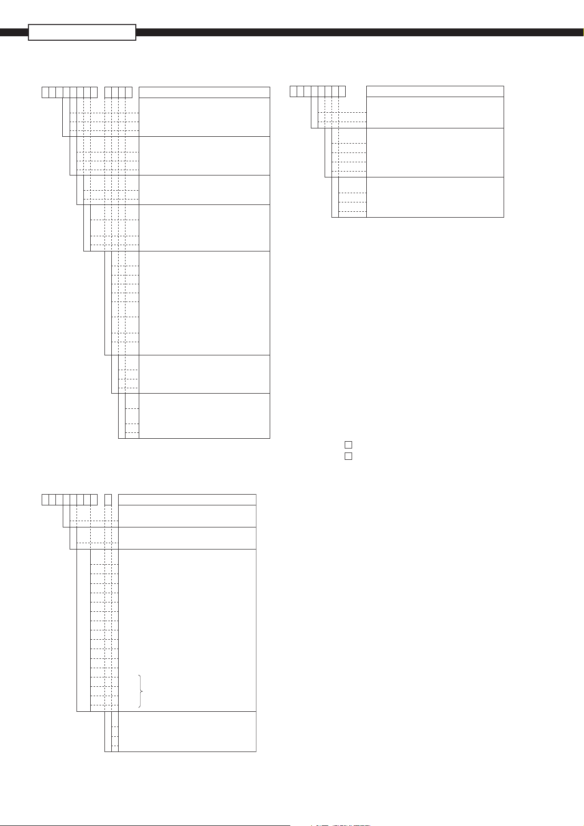
ZFK8, ZKM, ZTA
(Converter)
910111221 345678
-11MKZ
1
2
3
B
E
Z
1
2
Y
1
2
Y
1
2
3
4
5
6
7
J
E
C
Y
1
2
Note4) When you select this display, rich mode
(Exclusive-special cable)
921 345678
-1KRZRZ
K
R
YA
YB
YC
YD
YE
YF
YG
YH
YJ
YK
YL
YM
AA
BB
CC
DD
Connectable devices
For ZKM
Types
For R thermocouple
Conduit length Cable length
None 6m
None 10m
None 15m
None 20m
None 30m
None 40m
None 50m
None 60m
None 70m
None 80m
None 90m
None 100m
6m 6m
10m 10m
15m 15m
20m 20m
Cable end treatment
0
None
1
One side (detector side)
2
Both sides
Note5) For connection between detector and
converter, the conduit to be used should
be rainproof flexible type.
Description
Construction
IP66
IP67
Bench type
Output signal
4 to 20mA DC
0 to 1V DC
Other
Communication function
RS-232C
RS-485
Mounting bracket
None (Specify "None" when the bench
type is selected)
Mounting on panel surface
Pipe mounting
Optional Functions
None
Combustion efficiency display function Note4)
Blowdown
Auto calibration
Combustion efficiency indication
+ Blowdown Note4)
Combustion efficiency indication
+ Auto calibration Note4)
Blowdown + Auto calibration
Combustion efficiency indication + Blowdown
+ Auto calibration Note4)
Display language
Japanese
English
Chinese
Option
None (Specify "None" when the bench
type or the auto calibration is selected)
With valve
With valve + flowmeter
will be a simultaneous display.
Description
Note5
(Ejector)
21345678
11ATZ
1
2
B
C
D
E
1
3
5
Measured gas temperature
For high temperatures (+1500°C max.)
General-use (+800°C max.)
Insertion length [mm]
500
750
1000
150 0
Power supply
100V/115V AC 50/60Hz
200V/220V AC 50/60Hz
230VAC 50/60Hz
Description
SCOPE OF DELIVERY
Detector: Detector main unit × 1, Viton O ring ×
1, mounting screw (M5mm × 16) × 6,
thermal sticker × 1, fl ow guide tube (as
specifi ed) × 1, ceramic fi lter × 1, rain-
proof cover (as specifi ed) × 1, Instruction
manual × 1
Converter: Converter main unit × 1, mounting
bracket set, (as specifi ed) × 1
Accessories (AC250V 500mA T fuse ×
2, AC250V 2.5A T fuse × 2),
Instruction manual × 1
Ejector: Ejector main unit × 1, insertion tube × 1,
M16mm nut, and washer × 4, packing ×
1
Items to be prepared separately:
(1) Standard gas for calibration
Type ZBM
Type ZBM
NSH4-01 (up to 5% O2 range)
NSJ4-01 (over 5% O2 range)
(2) Reduction valve for standard gas (type ZBD61003)
(3) Flowmeter
Type; ZBD42203, 0.2 to 2L/min (for calibrating gas)
Type; ZBD42403, 1 to 10L/min (for ejector)
CAUTIONS
• If combustible gas (CO, H2 etc.) exists in the measured
gas, error will occur due to burning at the sensor section.
The inclusion of corrosive gas (Si vapor, alkaline metal, P,
Pb etc.) will shorten the life of the sensor.
• When the measured gas temperature is high (+300°C
or higher), the flange should be separated from the
furnace wall in order to bring the detector fl ange surface
temperature below the specifi ed value +125°C). The fl ow
guide should be attached in the direction in which the gas
fl ow to the detector decreases.
• When much dust is included in the gas, the fl ow guide
tube should be attached at an inclination so that the fl ow
goes from below to above. And the fl ow guide tube
should be attached in the direction in which the gas fl ow
to the detector decreases.
• In the case of a refuse incinerator, automatic blow down
of the fl ow guide should not be performed (to prevent
corrosion of the fl ow guide tube due to drainage). Blowdown should be performed manually when change in
the indication has become very little with the furnace
stopped.
4
Page 5
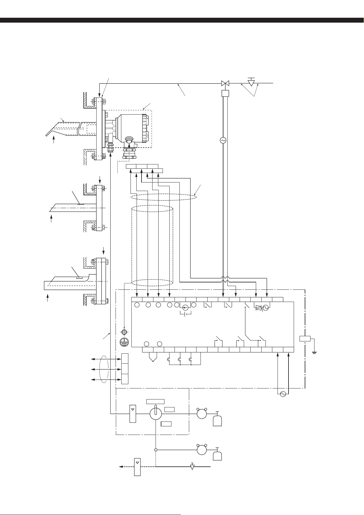
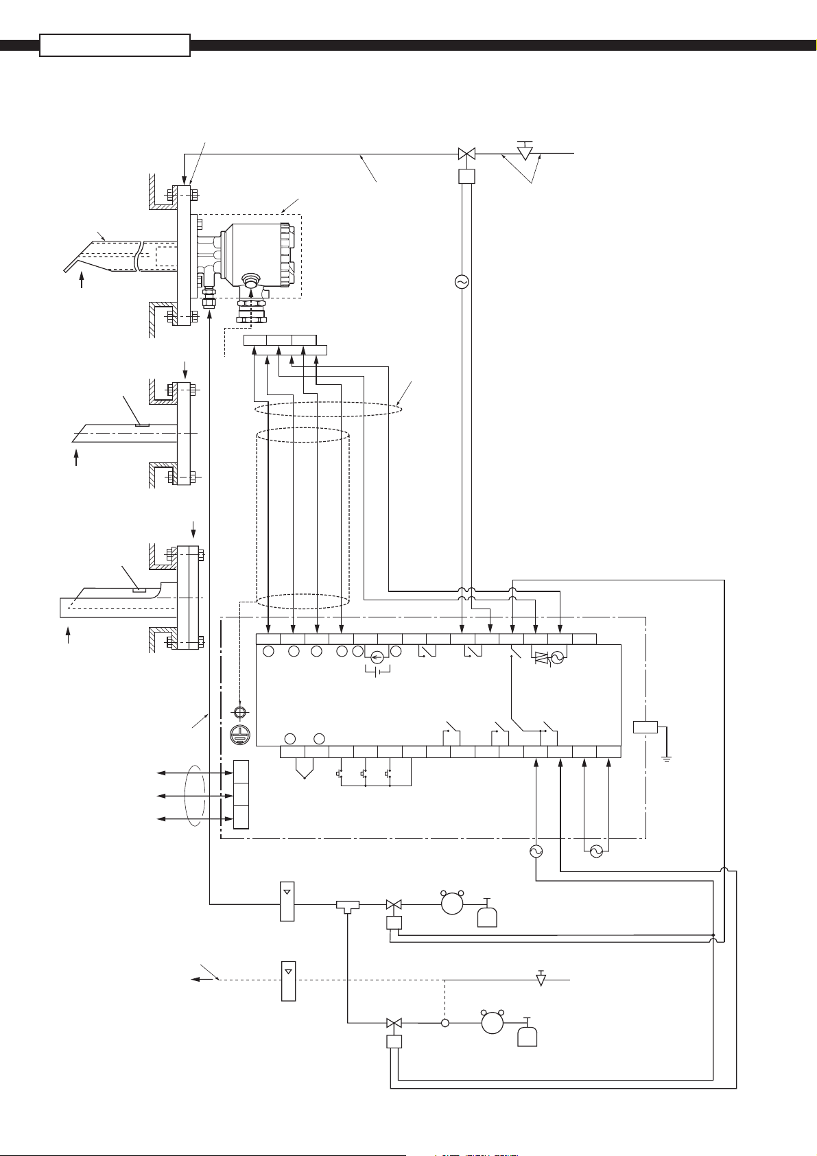
CONFIGURATION
Flow guide tube system (with valve)
Rc1/4
(upper side blow port should be selected)
Blow-down, 200 to 300kPa
Solenoid valve
(not supplied)
Reduction valve
(unnecessary when supply air pressure is
200 to 300kPa)
Supply air
Flow guide tube
Gas temperature.
600ºC max.
Sample gas outlet
Gas temperature.
600ºC max.
Flow guide tube
for high particulate
Sample gas outlet
*2
Ref. air
Blue
6
Ye l l o w
Rainproof cover
Detector
(ZFK8)
123
45
Red
White
Black
White
15ASGP
tube equivalent
or φ10/φ8 PTFE
pipe or copper pipe
(not supplied)
AC power
supply
Rainproof flexible
conduit.
(Max. 20m)
15ASGP
tube equivalent
or φ10/φ8 PTFE
pipe or copper pipe
(not supplied)
Gas temperature.
600ºC max.
Flow guide tube for high
particulate with cover
φ6mm or φ1/4 inch tube
for calibration gas
(not supplied)
RS232C
or
RS485
(option)
(Option)
*2 Ref. air
to Detector
115234567891011121314
+
O2 input
*4
−
O2
Thermocouple
for combustion
control
+
TC2
+
TC1
Thermocouple
input
−
16
+
−
4 to 20mA DC
Contact input
DI1
17
AO
or
Analog output
or 0 to 1V DC
DI2 DI3
18 19
−
FAULT BLOW
Fault
contact
output
ALARM
DICOM
20
Alarm
contact
output
21 22
Blow
contact
output
Maintenance
contact
output
MAINTE
23 24
ZV
GAS
Calibrating
gas contact
output
ZERO
Calibrating gas
contact output
COM
25 28
12 3
TM-2
Flowmeter
Val ve
MEASURE
Reduction valve
(ZBD6)
ZERO
Standard gas
for zero point (ZBM)
*1
Span gas (ZBM)
Note:
Flowmeter
SPAN
Reduction valve
(ZBD6)
*1 Air supply
Reduction valve
(0.2 to 0.5L/min)
(not supplied)
(unnecessary when
supply air pressure
is 50 to 100kPa)
Converter (ZKM)
TM-1
HEATER
AC power
SPAN
supply
GAS
AC
L
NSV
26 27
*1 Standard gas or instrumentation air
can be used in place of span gas.
*2 Instrument quality air or bottled air is
available as reference air instead of
ambient air.
*3 Protective earth.
*4 Connect the shield of a exclusive cable
with the ground terminal in the converter.
*3
PE
5
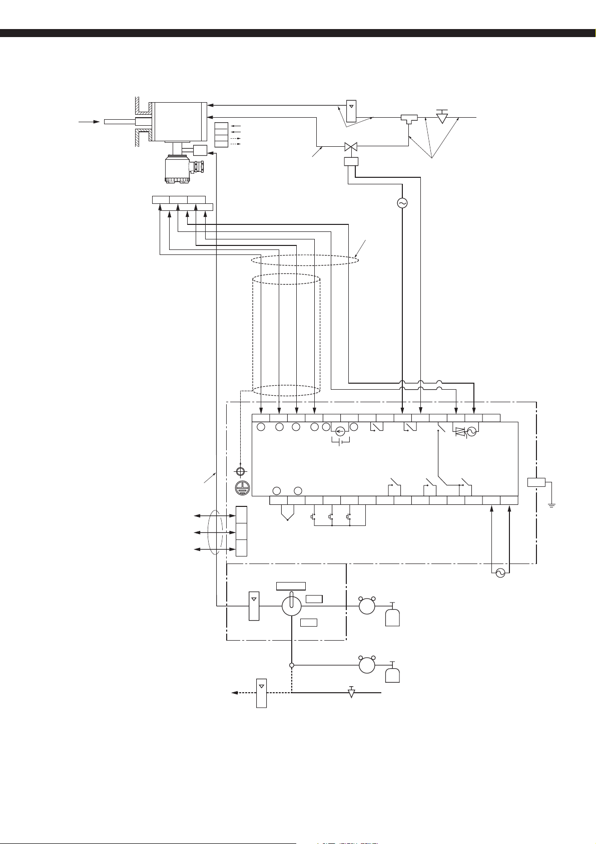
Page 6
ZFK8, ZKM, ZTA
Flow guide tube system
Rc1/4
(upper side blow port should be selected)
Blow-down, 200 to 300kPa
Solenoid valve
(not supplied)
Reduction valve
(unnecessary when supply air pressure is
200 to 300kPa)
Supply air
Flow guide tube
Gas temperature.
600ºC max.
Sample gas outlet
Gas temperature.
600ºC max.
Flow guide tube
for high particulate
Sample gas outlet
*2
Ref. air
Blue
6
Rainproof cover
123
Ye l l o w
Detector
(ZFK8)
45
Red
White
Black
White
15ASGP
tube equivalent
or φ10/φ8 PTFE
pipe or copper pipe
(not supplied)
AC power
supply
Rainproof flexible
conduit.
(Max. 20m)
15ASGP
tube equivalent
or φ10/φ8 PTFE
pipe or copper pipe
(not supplied)
Gas temperature.
600ºC max.
Flow guide tube for high
particulate with cover
+
O2
O2 input
*4
115234567891011121314
φ6mm or φ1/4 inch tube
for calibration gas
(not supplied)
12 3
RS232C
or
RS485
(option)
TM-2
Flowmeter
(ZBD4)
(1 to 1.5L/min)
*2 Ref. air
to Detector
(0.2 to 0.5L/min)
(not supplied)
*1 Standard gas or instrumentation air can be used in place of span gas.
Note:
*2 Instrument quality air or bottled air is available as reference air instead
of ambient air.
*3 Protective earth.
*4 Connect the shield of a exclusive cable with the ground terminal in
the converter.
+
−
Thermocouple
Thermocouple
for combustion
control
+
−
TC2
16
TC1
input
+
−
Analog output
4 to 20mA DC
or 0 to 1V DC
Contact input
DI1
17
Joint
AO
−
or
DI2 DI3
18 19
Solenoid valve
(not supplied)
Solenoid valve
(not supplied)
FAULT BLOW
Fault
contact
output
Alarm
contact
output
ALARM
DICOM
21 22
20
Reduction valve
(ZBD6)
Converter (ZKM)
TM-1
ZV
ZERO
GAS
Calibrating
Blow
gas contact
contact
output
output
Maintenance
contact
output
MAINTE
23 24
Standard gas
for zero point (ZBM)
Reduction valve
(unnecessary when supply air pressure is 50 to 100kPa)
HEATER
Calibrating gas
contact output
COM
25 28
SPAN
GAS
26 27
AC power
supply
NSV
AC
L
AC power
supply
*1 Air supply
Reduction valve
(ZBD6)
Span point
*1
Standard gas for
span point (ZBM)
*3
PE
6
Page 7
Ejector system (with valve)
Ejector (ZTA)
Gas temperature.
1500ºC max.
Detector (ZFK8)
123
6
Black
Ye l l o w
Bule
Red
Flowmeter
Ejector (5 to 10L/min)
Power supply
1
2
Heater temperature drop
4
5
Alarm
Copper pipe
φ10/φ8mm
(not supplied)
45
White
White
(ZBD)
Copper pipe φ6/φ4mm
(not supplied)
Solenoid valve
(not supplied)
AC power
supply
Rainproof flexible
conduit.
(Max. 20m)
Reduction valve
(unnecessary when supply air pressure
is 200 to 300kPa )
Joint
Copper pipe φ10/φ6mm
(not supplied)
Supply air
φ6mm or φ1/4 inch tube
for calibration gas
(not supplied)
RS232C
or
RS485
(option)
(Option)
*2 Ref. air
to Detector
1152 3 4 5 6 7 8 9 10 11 12 13 14
+
O2 input
*4
−
O2
Thermocouple
for combustion
control
+
TC2
+
TC1
Thermocouple
input
−
16
+
−
Analog output
4 to 20mA DC
or 0 to 1V DC
Contact input
DI1
17
AO
or
DI2 DI3
18 19
−
FAULT BLOW
Fault
contact
output
ALARM
DICOM
20
Alarm
contact
output
21 22
Blow
contact
output
Maintenance
contact
output
MAINTE
23 24
ZV
GAS
Calibrating
gas contact
output
ZERO
Calibrating gas
contact output
COM
12 3
TM-2
Flowmeter
Val ve
MEASURE
Reduction valve
(ZBD6)
ZERO
Standard gas
for zero point (ZBM)
*1
Span gas (ZBM)
Flowmeter
SPAN
Reduction valve
(ZBD6)
*1 Air supply
Reduction valve
(0.2 to 0.5L/min)
(not supplied)
(unnecessary when
supply air pressure
is 50 to 100kPa)
TM-1
HEATER
Heater
AC power
SPAN
supply
GAS
AC
NSV
26 27
25 28
*1 Standard gas or instrumentation air
Note:
can be used in place of span gas.
*2 Instrument quality air or bottled air is
available as reference air instead of
ambient air.
*3 Protective earth.
*4 Connect the shield of a exclusive cable
with the ground terminal in the converter.
L
AC power
supply
PE
*3
7
Page 8

ZFK8, ZKM, ZTA
Ejector system
Gas temperature.
1500ºC max.
Detector (ZFK8)
6
Bule
Ejector (ZTA)
123
Black
Ye l l o w
Red
Flowmeter
Ejector (5 to 10L/min)
Power supply
1
2
Heater temperature drop
4
5
Alarm
Copper pipe
φ10/φ8mm
(not supplied)
45
White
White
(ZBD)
Copper pipe φ6/φ4mm
(not supplied)
Solenoid valve
(not supplied)
AC power
supply
Rainproof flexible
conduit.
(Max. 20m)
Reduction valve
(unnecessary when supply air pressure
is 200 to 300kPa )
Joint
Copper pipe φ10/φ6mm
(not supplied)
Supply air
115234567891011121314
+
−
O2
O2 input
*4
Thermocouple
for combustion
φ6mm or φ1/4 inch tube
for calibration gas
(not supplied)
control
+
TC2
12 3
RS232C
or
RS485
(option)
TM-2
(1 to 1.5L/min)
Flowmeter
(ZBD4)
*2 Ref. air
to Detector
(0.2 to 0.5L/min)
(not supplied)
*1 Standard gas or instrumentation air can be used in place of span gas.
Note:
*2 Instrument quality air or bottled air is available as reference air instead
of ambient air.
*3 Protective earth.
*4 Connect the shield of a exclusive cable with the ground terminal in
the converter.
+
−
TC1
Thermocouple
input
−
DI1
16
17
Joint
AO
+
or
Analog output
4 to 20mA DC
or 0 to 1V DC
Contact input
DI2 DI3
18 19
Solenoid valve
(not supplied)
Solenoid valve
(not supplied)
−
FAULT BLOW
Fault
contact
output
ALARM
DICOM
20
Blow
contact
output
Alarm
Maintenance
contact
output
MAINTE
21 22
Reduction
valve (ZBD6)
ZV
ZERO
GAS
Calibrating
gas contact
output
contact
output
23 24
Standard gas
for zero point (ZBM)
Reduction valve (unnecessary when
supply air pressure is 50 to 100kPa)
HEATER
Calibrating gas
contact output
COM
25 28
SPAN
GAS
26 27
AC power
supply
NSV
*1 Air supply
Reduction
valve (ZBD6)
Span gas
*1 Standard gas for
span point (ZBM)
AC
TM-1
L
AC power
supply
*3
PE
8
Page 9

DEVICE CONFIGURATION
The device to be combined differ according to the conditions of the gas to be measured. Select the devices to be combined
with reference to the following table.
Measured gas Device confi guration
Application Temperature Gas Flow DUST Protection
cover
General-use
(boiler)
For corrosive
gas (refuse
600ºC or
less
600ºC or
less
5 to 20m/s Less than 0.2g/Nm
Less than 10g/Nm
5 to 20m/s Less than 1g/Nm
Less than 10g/Nm
incinerator)
Less than 25g/Nm
Less than 25g/Nm
General-use
(boiler)
Note (1) Dust volume is approximate value.
(2) Instrument quality air or bottled air is available as reference air by selecting detector with reference air inlet.
800ºC or
less
1500ºC or
less
Less than
1m/s
Less than
1m/s
Less than 1g/Nm
Less than 1g/Nm
3
—
3
—
3
—
3
—
3
no
3
yes
3
—
3
— SIC tube
Note Detector type Converter
type
Fuel; gas, oil
Fuel: coal
ZFK8R
ZFK8R
5
5- A -1
5
5- C -1
ZKM —
ZKM —
with blow down
Included low moisture
Included low moisture
ZFK8R
ZFK8R
5
5- B -2
5
5- C -2
ZKM —
ZKM —
with blow down
Included low moisture
ZFK8R
6
5- D -2
ZKM —
with blow down
Included high moisture
ZFK8R
6
5- E -2
ZKM —
with blow down
SUS316 tube
ZFK8R
5-0Y0 -1
ZKM ZTA2
with blow down
ZFK8R 5-0Y0 -1
ZKM ZTA1
with blow down
Ejector
type
9
Page 10

ZFK8, ZKM, ZTA
OUTLINE DIAGRAM
φ
80
φ
67
6-φ6
60°
φ
80
φ
67
6-φ6
(Unit:mm)
26
φ
Ref. Air inlet (to order)
SUS316,for
or 1/4 inch tube
φ6/φ
4 tube
Approx.62
Filter
Approx.62
Detector (ZFK8)
Temp.Proof cover
5
(To order)
Approx.30
Calibration gas inlet
(To order)
SUS316,for
or 1/4 inch tube
φ6/φ
4 tube
5
Temp.proof cover
(to order)
Approx.132
Approx.130
Approx.132
Approx.130
Terminal box
Ground-wire
Screw: M4
Exclusive
Cable gland
Terminal box
EXTERNAL CONNECTION DIAGRAM
79
φ
Heater Thermocouple
85
φ
125.5
1
Black / White/ red / White/ yellow / blue
2-core wire 4-core wire
3
2
Exclusive-special cable
45 6
Element output
60°
26
φ
ZFK8R 3
Ball valve
Ref. air inlet (to order)
SUS316,for
or 1/4 inch tube
φ6/φ
4 tube
Calibration gas inlet
Rc1/4 INT.THD.
Filter
Approx.100
Valve handle
79
φ
125.5
Ground-wire
screw: M4
Exclusive cable gland
85
φ
10
Page 11

Sensor unit (ZFK8YY)
(132.7)
(88.4) 3.5
(?17.5)
20
4-φ3.5(Mount for detector)
TK4J4664R0
45°
45°
T+
φ
35
40
S+
6
madeinjapan
5
S-
H
1
3
4
2
H
T-
Flow guide tube
12
Approx. L
Approx. 20
Gas inlet
34
20
155
130
67
Z F K 8 R 5 - 5 A 3
5
7
1
Oxygen detector
Oxygen detector
Gas outlet
6-M5
detector side
8–15
MTG. holes
Code 11th
L (m)
MASS
Approx.(kg)
3
0.3
2.7
57
0.5
0.75
4.1
3.3
1
1.0
4.8
Z
L=
(to order)
Flow guide tube (with blow-down nozzle)
18
Approx. L
Approx. 20
3
60.5
67
Gas inlet
6-M5
detector side
Gas outlet
Blow down air inlet
155
130
67
4-Rc1/4
with plug int.thd.
8–15
MTG. holes
Z F K 8 R 5 - 5 C 3
3
0.3
3.0
57
0.5 0.75 1.0
3.8
Code 11th
L (m)
Mass
Approx.(kg)
4.8
1
5.7
5
7
1
L=
(to order)
Z
11
Page 12

ZFK8, ZKM, ZTA
Flow guide tube (for high particulate)
4 - Rc 1/4
with plug int thd.
Flange: JIS 5K80A FF
ZFK MTG. position
Packing
Gas flow
180
145
Gas outlet
Tube (50A SCH40)
29.5
800
67
8 - 19
MTG. hole
185
Blow down air inlet
Select an upper port to
avoid the condensation
in the piping
Z F K 8 R 5 - 6 D
50
30
Code 11th
Mass
Approx.(kg)
L (m)
3
0.3
4.5
3
5
7
1
57
0.5 0.75 1.0
5.6
7.0
1
8.3
Z
L=
(to order)
4 - Rc 1/4
with plug int thd.
Flange: JIS 5K80A FF
ZFK MTG. position
Packing
Gas flow
Flow guide tube (for high particulate with cover)
180
145
Blow down air inlet
Select an upper port to
avoid the condensation
in the piping
(175)
50
30
Gas outlet
(790)
67
29.5
800
8 - 19
MTG. holes
Z F K 8 R 5 - 6 E
3
Code 11th
L (m)
Mass
Approx.(kg)
0.3
7.1
57
0.5 0.75 1.0
9.0
11.4
3
5
7
1
1
Z
L=
(to order)
13.6
Protection tube (65A SCH40)
12
(38)
Tube (50A SCH40)
Page 13

Flow guide tube (
12
Approx. L
3
Gas inlet
67
60.5
Approx. 40
for corrosive gas)
155
130
67
Oxygen detector
Viewed from P direction
105
140
(JIS 10K65ARF)
8
Gas inlet
25
Ejector air
outlet
(Rc1/4)
Gas outlet
6-M5
detector side
Ejector (ZTA)
Approx. L
42.7
L [mm]
500 750 1000 1500
30
EXTERNAL CONNECTION DAIAGRAM
1 2 3 4 5
AC
power supply
AC100/110V
AC200/220V
AC230V
Heater temp.drop alarm
4-M16 bolt
P
Z F K 8 R 5 - 5 B 3
3
Code 11th
L (m)
MASS
Approx.(kg)
8- 15
MTG. holes
190
217
40
35
Blow -down air inlet
(Rc1/4)
Ejector air inlet
(Rc1/4)
40
0.5
0.3
3.3
170
50
45
Cable gland
(A15C)
57
4.5
0.75
6.1
5
7
1
1
1.0
7.6
Detector
(ZFK8)
Z
L=
(to order)
13
Page 14
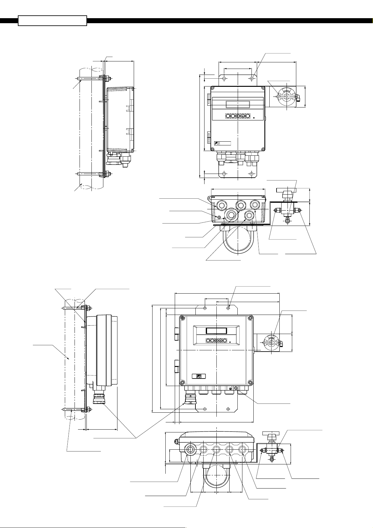
ZFK8, ZKM, ZTA
Converter (ZKM1)
<IP66>
U bolts M8
(option)
Mounting for
2B pipe
2.5
2.5
75
100
Mounting hole
ø9
2-
100
72
1010
Valve (option)
A
E
S
M
N
170
O
OxygenAnalyzer
MODE
ENTER
ESC
POWER
Z
55
S
270
ZKM
OxygenAnalyzer
Calibration gas outlet
(for F6 tube)
153
For contact Input/output
35
Earth terminal (M4)
For sensor (coupling)
F23.5/F15.8 tube
For
Mtg. Plate
For communication
For output
Zero gas inlet
(for F6 tube)
Span gas inlet
(for F6 tube)
62.5
For power supply
Converter (ZKM2)
<IP67>
Bracket
Mounting for
2B pipe
U bolts M8 (option)
5.7
U bolts M8 (option)
95
For sensor (coupling)
For φ23.5/φ15.8 tube
498
312
953.2
20
220
Mounting hole 4-
φ9
324
72
195
Valve (option)
59
A
E
S
.
MODE ESC
ENTER
POWER
M
N
O
Z
55
S
Earth terminal (M4)
14
39
230
Calibration gas outlet
(for φ6 tube)
65
14
For sensor (coupling)
For φ23.5/φ15.8 tube
For contact Input/output
(G1/2)
For communication
(G1/2)
40 40 40 40
Zero gas inlet
(for φ6 tube)
For power supply
(G1/2)
For output
(G1/2)
Span gas inlet
(for φ6 tube)
Page 15
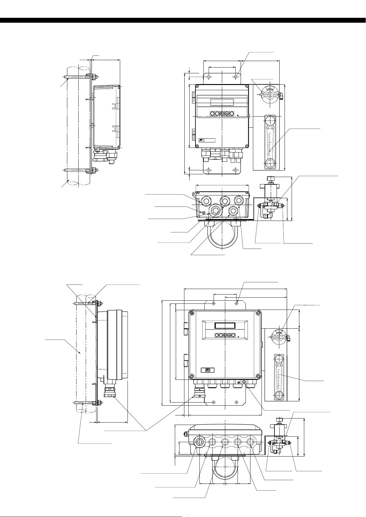
Converter (ZKM1)
<IP66>
2.5
U bolts M8
(option)
2.5
75
100
Mounting hole
ø9
2-
100
72
1010
Valve (option)
A
E
S
M
N
O
OxygenAnalyzer
Z
S
Mounting for
2B pipe
Converter (ZKM2)
<IP67>
Bracket
U bolts M8 (option)
For contact Input/output
Earth terminal (M4)
For sensor (coupling)
F23.5/F15.8 tube
For
Mtg. Plate
For communication
20
170
270
MODE
ESC
ZKM
OxygenAnalyzer
153
For power supply
ENTER
POWER
Flowmeter (option)
230
Calibration gas outlet
(for F6 tube)
(125)
62.5
Zero gas inlet
(for F6 tube)
Span gas inlet
(for F6 tube)
For output
Mounting hole 4-
φ9
324
72
195
Valve (option)
Mounting for
2B pipe
5.7
For sensor (coupling)
For φ23.5/φ15.8 tube
U bolts M8 (option)
59
A
E
S
M
MODE ESC
ENTER
POWER
N
O
Z
S
220
498
312
230
Flowmeter
(option)
Earth terminal
14
230
(M4)
Calibration gas outlet
(for φ6 tube)
95
180
65
Span gas inlet
(for φ6 tube)
For sensor (coupling)
For φ23.5/φ15.8 tube
For contact Input/output
(G1/2)
953.2
39
For communication
40 40 40 40
Zero gas inlet
(for φ6 tube)
For power supply
(G1/2)
For output
(G1/2)
(G1/2)
15
Page 16

ZFK8, ZKM, ZTA
Converter (ZKM3)
<Bench type>
70.6
MadeinJapan
POWERAC
SER.NO.
TYPE
OUTPUTDC
MFD
OXYGENTRANSM
FujiElectricsystemsCo.,Ltd.
50/60Hz60VA
ITTER
10
172
4-F4.5 Mounting hole
163.5
143.5
OxygenAnalyzer
FAULT
ALARM
BLOW
MAIN-
TENANCE
ENTER
POWER
FUSET0.5A
HEATER
FUSET2.5A
POWER
ZV HEATER
COMSV
POWER
MODE ESC
注 意
変換器へ供給する電源電圧は、接続される
検出器の電源電圧に合わせてください。
CAUTION
Powersupplymustbeselected
thesamevoltageofdetector.
TC1+−AO
2
O
+ −
+−
1152 3 4 5 6 7 8 9 10 11 12 13 14
16 17 18 19 20 21 22 23 24 25 2826 27
DI1 DI2 DI3
DICOM
TC2
+−
182
ON
OFF
AC
N
L
*2
Exclusive
cable
Ground
terminal
M4
O
sensor
O2 sensor
input
2
thermocouple
input
1152 3 4 5 6 7 8 9 1011121314
+
O
++
−
TC2
TC1
−
2
+
DI1
16
Thermocouple
input type R
(not supplied)
Contact input
Short circuit : on (Current 5mA)
Open : off (Voltage 5V)
EXTERNAL TERMINAL (TM1) / Terminal M3
Analog
output
4-20mA DC
or 0-1V DC
−−
AO
or
Fault
contact output
250V AC/3A
30V DC/3A
FAULT
ALARM MAINTE
DICOM
20
17
DI2 DI3
18 19
Blow contact
250V AC/3A
30V DC/3A
BLOW
21 22
Alarm
contact output
250V AC/3A
30V DC/3A
output
ZV
23 24
Maintenance
contact output
250V AC/3A
30V DC/3A
*1
O
sensor
2
heater power
output
ZERO
GAS
HEATER
SPAN
GAS
26 27
25 28
Calibrating gas
contact output
250V AC/3A
30V DC/3A
AC
NSVCOM
AC
Power supply
input
100 to120V AC
200 to 240V AC
COMMUNICATION TERMINAL (TM2) /INSERTION TERMINAL
Note 1) The heater power supply is the same
Note 2) Be sure to connect the shield of the
RS232C
RS485
Terminal number
1
2
TXD
RXD
TRX+
TRX–
3
GND
GND
Remarks
Standard
Option
L
as the converter power supply.
cable to the ground in the main body.
Caution on Safety
*Before using this product, be sure to read its instruction manual in advance.
International Sales Div.1
Sales Group
Gate City Ohsaki, East Tower, 11-2, Osaki 1-chome,
Shinagawa-ku, Tokyo 141-0032, Japan
http://www.fesys.co.jp/eng
Phone: 81-3-5435-7280, 7281 Fax: 81-3-5435-7425
http://www.fic-net.jp/eng
Information in this catalog is subject to change without notice.
Printed in Japan
 Loading...