

Page 1

Instruction Manual
Remote Keypad "TP-E1"
Thank you for purchasing our Remote Keypad TP-E1.
• This product is designed to remotely control the FRENIC-Mini series of inverters. Read
through this instruction manual and be familiar with the handling procedure for correct use.
• Improper handling blocks correct operation or causes a short life or failure.
• Deliver this manual to the end user of the product. Keep this manual in a safe place until the
Remote Keypad is discarded.
• For the usage of inverters and optional equi pment, refer to the instruction manuals prepared
for the FRENIC-Mini series of inverters and its optional equipment.
Fuji Electric FA Components & Systems Co., Ltd. INR-SI47-0843a-E
Page 2

Copyright © 2003 Fuji Electric FA Components & Systems Co., Ltd.
All rights reserved.
No part of this publication may be reproduced or copied without prior written permissi on from Fuji
Electric FA Components & Systems Co., Ltd.
All products and com pany names mentioned in this manual are trademarks or registered trademarks
of their respective holders.
The information contained herein is subject to change without prior notice for improvement.
Page 3

Preface
Thank you for purchasing our Remote Keypad "TP-E1."
The Remote Keypad allows you to remotely operate FRENIC-Mini series of inverters. Using this
remote keypad, you can perform the operations that are available on the built-in keypad on
FRENIC-Mini inverter, such as running and stopping the motor, monitoring the running status, and
setting the function codes.
In addition, you can perform "data copying": You can read function code data from an inverter, copy
(write) it into another inverter, or verify it.
To use the Remote Keypad, make sure that the FRENIC-Mini inverter is equipped with the RS485
Communications Card (OPC-C1-RS), and connect the two using an optional Remote Operation
Extension Cable (CB-5S, CB-3S, or CB-1S, depending on the distance).
This manual describes how to install the Remote Keypad and the "data copying." For other
operations that are common to the built-in keypad, refer to the FRENIC-Mini Instruction Manual
(INR-SI47-0791-E), Chapter 3.
Before installing and using the Remote Keypad, read through this manual in conjunction with the
FRENIC-Mini User's Manual and make yourself familiar with its proper use. Improper use may
prevent normal operation or cause a failure or reduced life of the inverter.
Related Publications
Listed below are other publications on the FRENIC-Mini to be consulted in conjunction with this
manual as necessary.
• FRENIC-Mini User’s Manual (MEH446)
• RS485 Communications User’s Manual (MEH448)
• Catalog (MEH441/MEH451)
• Application Guide (MEH449)
• FRENIC-Mini Instruction Manual (INR-SI47-0791-E)
• RS485 Communications Card Installation Manual (INR-SI47-0773)
• Rail Mounting Base Installation Manual (INR-SI47-0774)
• Mounting Adapter Installation Manual (INR-SI47-0775)
• Built-in Braking Resistor Installation Manual (INR-SI47-0838)
Note that these publications are subject to change without notice. Make sure that you have the most
up-to-date versions at all times.
Safety precautions
Before proceeding with installation, connecting, cabling, wiring, operation, inspection or
maintenance, read this manual thoroughly. Make sure also that you have sound knowledge of the
product, and familiarize yourself with all safety information and precautions.
Safety precautions are classified into the following two categories in this manual.
Failure to heed the information indicated by this symbol may
lead to dangerous conditions, possibly resulting in death or
serious bodily injuries.
Failure to heed the information indicated by this symbol may
lead to dangerous conditions, possibly resulting in minor or
light bodily injuries and/or substantial property damage.
Failure to heed the information contained under the CAUTION title can also result in serious
consequences. These safety precautions are of utmost importance and must be observed at all
times.
i
Page 4
Operation
• Be sure to install the terminal block cover before turning the power on. Do not remove the
cover during power application.
Otherwise electric shock could occur.
• Do not operate switches with wet hands.
Doing so could cause electric shock.
• If the retry function has been enabled, the inverter may automatically restart after tripping,
depending on its cause, causing the motor driven by it to start rotating. In designing a
system or a facility using the motor driven by the FRENIC-Mini, make sure that such
automatic restart would not cause any personal injury, damage to equipment, or other
unintended incidents.
• If the stall prevention function has been selected, the inverter may operate at an
acceleration/deceleration time or frequenc y different from the set ones. Design the
machine so that safety is ensured even in such cases.
Otherwise an accident could occur.
• The
• If an alarm reset is made with the operation signal turned on, a sudden start will occur.
Otherwise an accident could occur.
• If you have selected "Active" as the mode of Restart after momentary power failure (F14 =
• If you set the function codes wrongly or without completely understanding the instruction
An accident or injuries could occur.
• Do not touch the inverter terminals while the power is applied to the inverter even if the
Doing so could cause electric shock.
key is only effective when function setting (Function code F02) has been
established to enable the
disable the STOP key priority function and enable command (FWD) or (REV), you cannot
stop the inverter output by the
Check that the operation signal is turned off in advance.
4 or 5), the inverter will automatically restart, causing the motor driven by it to start
rotating. In designing a system or a facility using the motor driven by the FRENIC-Mini,
make sure that safety is secured even in such instances.
manuals and the FRENIC-Mini User's Manual, the motor may rotate with a torque or at a
speed not permitted for the machine.
inverter stops.
key. Prepare an emergency stop switch separately. If you
key on the built-in keypad.
ii
Page 5
Installation and cabling/wiring of option cards
• Do not operate the switch SW1 with wet hands.
Doing so could cause electric shock.
• Before starting installing the RS485 Communications Card, first turn off the power, wait
more than 5 minutes, and make sure, using a circuit tester or another appropriate
instrument, that the DC voltage between the P (+) and N (-) terminals of the main circuit is
less than +25 VDC.
Otherwise electric shock could occur.
• A high voltage is present just on the RS485 Communications Card. Do not remove the
cover for the control circuit terminal block (TB) while power is applied.
Doing so could cause electric shock.
• Generally, the sheath of control circuit wires is not reinforced by any insulation. If the
control circuit wires come into direct contact with the live main circuit terminal, therefore,
the sheath may break. Accordingly, there is a possibility that high voltage on the main
circuit may be applied to the control circuit wires. It is DANGEROUS. Be sure to keep the
control wires away from the live main circuit terminals.
An accident or electric shock could occur.
Disposal
• Handle this Remote Keypad or the RS 485 Communications Card as an industrial waste
when disposing of it.
Otherwise injuries could occur.
Others
• Never attempt to modify the inverter.
Doing so could cause electric shock or injuries.
GENERAL PRECAUTIONS
Drawings in this manual may be illustrated without covers or safety shields for explanation of
detail parts. Restore the covers and shields in the original state and observe the description in
the manual before starting operation.
iii
Page 6

How this manual is organized
This manual is made up of chapters 1 through 4.
Chapter 1. BEFORE USING THE REMOTE KEYPAD "TP-E1"
This chapter describes the points to check upon delivery and lists the inverters the Remote Keypad
is designed to interface with.
Chapter 2. INSTALLATION, CABLING, AND WIRING
This chapter describes how to install the Remote Keypad and the RS485 Communications Card and
how to connect them with each other.
Chapter 3. OPERATION USING THE REMOTE KEYPAD "TP-E1"
This chapter describes the functions of the Remote Keypad including data copying, as well as how to
operate the Remote Keypad.
Chapter 4. SPECIFICATIONS
This chapter lists the general specifications such as operating environments, communication
specifications and transmission specifications.
Icons
This manual uses the following icons:
Indicates information that should be observed to make full use of the features and functions
provided by this product and the neglect of which may result in an accident.
Refers you to related or more detailed information.
iv
Page 7

CONTENTS
Preface ................................................................i
Safety precautions..................................................i
How this manual is organized ..................................iv
Chapter 1 BEFORE USING THE
Chapter 2 INSTALLATION, CABLING,
Chapter 3 OPERATION USING THE
Chapter 4 SPECIFICATIONS .............................. 4-1
REMOTE KEYPAD "TP-E1" ............... 1-1
1.1 Check Points.............................................. 1-1
1.2 Inverters with which the Remote
Keypad Interfaces...................................... 1-1
AND WIRING ..................................... 2-1
2.1 Accessories and Parts Required
for Connection............................................ 2-1
2.2 Installing the Remote Keypad .................... 2-2
REMOTE KEYPAD "TP-E1" ............... 3-1
3.1 Familiarizing Yourself with the Remote
Keypad....................................................... 3-1
3.2 Operating the Remote Keypad................... 3-2
3.3 Data Copying ............................................. 3-3
4.1 General Specifications ............................... 4-1
4.2 Communication Specifications................... 4-2
4.3 Transmission Specifications....................... 4-2
v
Page 8
Chapter 1 BEFORE USING THE REMOTE KEYPAD "TP-E1"
1.1 Check Points
Unpack the package and check the following:
(1) The package contains the Remote Keypad and its instruction
manual (this book).
(2) There have been no problems during transportation. In
particular, no parts are damaged or have fallen out of place
nor are there any dents on the body.
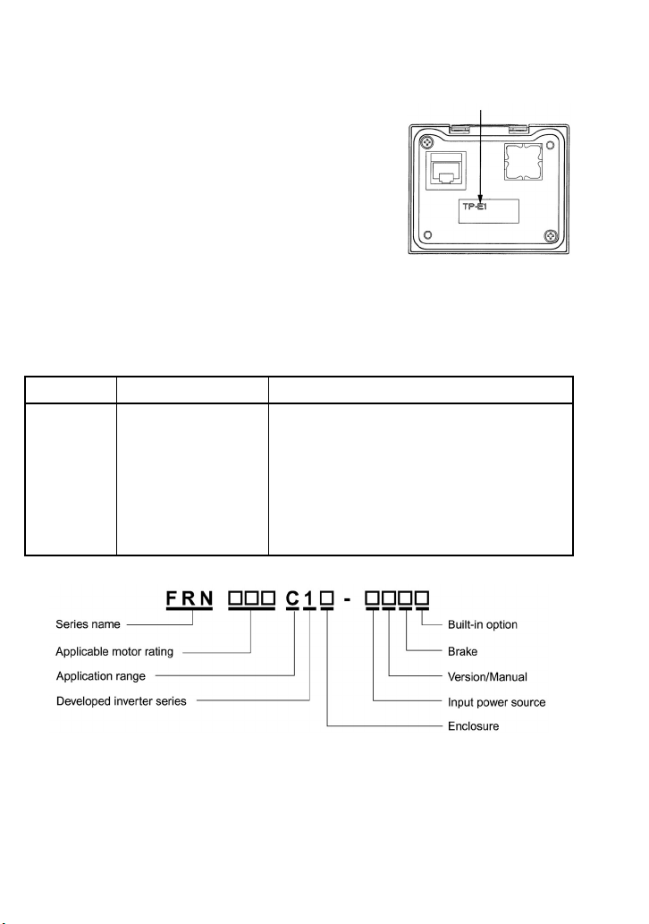
(3) The model name "TP-E1" is inscribed on the back of the
Remote Keypad as shown in Figure 1.1.
If you find any anomalies, contact your dealer or nearest Fuji
Figure 1.1 Back of Remote
Electric sales office.
1.2 Inverters with which the Remote Keypad Interfaces
The Remote Keypad TP-E1 interfaces with the following Fuji inverters:
Series Type of inverter* Remarks
FRENIC-Mini FRN
FRN
(Each
as shown below,
represented by an
alphanumeric character.)
C1S-
C1E-
has its meaning
The Remote Keypad is fully supported by inverters with
a ROM version of C1S10500 or above. (You can check
the inverter’s ROM version by entering
"Maintenance Information" (Menu #5) in Program
Mode.)
There are restrictions on the support for the Remote
Keypad TP-E1 by inverters with a ROM version of
C1S10499 or below. For details, contact your Fuji
Electric sales office.
Model name
Keypad TP-E1
5_14 in
* Type of inverter
For the details of the Inverter type ID, refer to the FRENIC-Mini Instruction Manual
(INR-SI47-0791-E), Chapter 1, Section 1.1 "Acceptance Inspection."
1-1
Page 9

Chapter 2 INSTALLATION, CABLING, AND WIRING
To connect the Remote Keypad to the FRENIC-Mini inverter, first install the RS485 Communications
Card (OPC-C1-RS) on the inverter, and then use an optional Remote Operation Extension Cable
(CB-5S, CB-3S, or CB-1S, depending on the distance) or an off-the-shelf LAN cable to interconnect
them.
2.1 Accessories and Parts Required for Connection
To connect your Remote Keypad TP-E1 to an inverter, you need the following devices and parts:
Accessories/Parts Type or Specifications Remarks
Remote Operation Extension Cable
(Note 1)
RS485 Communications Card OPC-C1-RS Install this into the inverter.
Screws (for mounting the Remote
Keypad)
(Note 2)
Note 1: Alternatively, you can use an off-the-shelf 10BASE-T/100BASE-TX LAN cable (straight type) that meets the
ANSI/TIA/EIA-568A Category 5 standard (maximum length: 20 m).
Recommended LAN Cable (for 1 m):
Manufacturer: Sanwa Supply, Co. Ltd.
Model: KB-10T5-01K
KB-STP-01K (shielded cable, EMC-compliant)
Note 2: Use the screws whose lengths are proper to thickness of the mounting enclosure.
CB-5S, CB-3S, or CB-1S You have a choice of three lengths:
M3 x 12 Get 2 screws beforehand.
5 m, 3 m, and 1 m.
2-1
Page 10

2.2 Installing the Remote Keypad
To mount the Remote Keypad on an enclosure, follow the steps below.
Installation Procedures
Follow the steps below after completing the cabling work for the inverter. First, power off the inverter.
To install the Remote Keypad on an enclosure (see Figure 2.1):
c Cut two square holes on the enclosure as shown in Figure 2.3.
d Mount the Remote Keypad onto the enclosure.
e Install the RS485 Communications Card on the inverter.
f Insert the connector on one end of the Remote Operation Extension Cable or LAN cable into the
RJ-45 modular jack on the Remote Keypad.
g Insert the connector on the other end of the cable into the RJ-45 modular jack on the RS485
Communications Card mounted on the FRENIC-Mini.
To use the Remote Keypad in hand (see Figure 2.2):
Follow steps
e to g above.
Figure 2.1 To Install the Remote Keypad on an
Enclosure
2-2
Figure 2.2 To Use the Remote
Keypad in Hand
Page 11

To install the Remote Keypad on an Enclosure
c Cut a single square hole and two screw holes in the enclosure as shown in Figure 2.3.
Figure 2.3 Dimensions of Square Hole and Screw Holes
d Mount the Remote Keypad TP-E1 onto
the enclosure with 2 screws as shown in
Figures 2.3 and 2.4.
(Recommended tightening torque:
0.7 N•m)
RJ-45 Modular jack
Enclosure
Figure 2.4 Mounting Remote Keypad TP-E1
2-3
M3 x 12
(to be prepared
by customer)
Page 12

e Installing the RS485 Communications Card
• Do not operate the switch SW1 with wet hands.
Doing so could cause electric shock.
• Before starting installing the RS485 Communications Card, first turn off the power, wait
more than 5 minutes, and make sure, using a circuit tester or another appropriate
instrument, that the DC voltage between the P (+) and N (-) terminals of the main circuit is
less than +25 VDC.
Otherwise electric shock could occur.
• A high voltage is present just on the RS485 Communications Card. Do not remove the
cover for the control circuit terminal block (TB) while power is applied.
Doing so could cause electric shock.
• Generally, the sheath of control circuit wires is not reinforced by any insulation. If the
control circuit wires come into direct contact with the live main circuit terminal, therefore,
the sheath may break. Accordingly, there is a possibility that high voltage on the main
circuit may be applied to the control circuit wires. It is DANGEROUS. Be sure to keep the
control wires away from the live main circuit terminals.
An accident or electric shock could occur.
Be sure to turn SW1 (termination resistor on/off
switch) on the RS485 Communications Card to the
OFF position as shown at right. (Upon shipment from
the factory, SW1 is set to OFF.)
Model name
SW1
Install the RS485 Communications
Card following the steps below.
1) If the control circuit terminal
block (TB) cover is in place,
remove it by inserting your
finger in the cutout (near
"PULL") in the bottom of it
and then pulling it towards
you.
Figure 2.5 Setting of SW1 on RS485
Figure 2.6 Removing the Control Circuit Terminal Block Cover
2-4
Communications Card
Page 13

2) Align the RS485 Communications Card with the latch and mount it onto the FRENIC-Mini
so that the connector CN1 on the Card is properly inserted.
Figure 2.7 Installing the RS485 Communications Card
3) Before putting the control circuit TB cover, snip off the barrier of the RS485
Communications Cable outlet with nippers (Figure 2.6).
4) Fit the latches provided on the upper end of the control circuit TB cover into the openings in
the front face of the FRENIC-Mini, and then close the TB cover. Take care not to pinch
control signal wires/cables between the TB cover and the body of the FRENIC-Mini.
f Insert the connector on one end of the Remote Operation Extension Cabl e or LAN cable into the
RJ-45 modular jack on the Remote Keypad TP-E1 (see Figure 2.8).
g Insert the connector on the other end of the cable into the RJ-45 modular jack on the RS485
Communications Card mounted on the FRENIC-Mini.
Figure 2.8 Connecting Remote Keypad to the RS485 Communications Card with Remote Operati on
Extension Cable or LAN Cable
To use the Remote Keypad in hand
Follow steps e to g above.
2-5
Page 14

To comply with EMC Directives
Use an EMC filter built-in inverter.
All the connecting cabl es and wires must be
shielded. As shown in Figure 2.9, remove outer
sheath of the cable to bare the shield layer for
clamping. Ground the shield onto the EMC flange
for EMC compliance using clamps provided.
Length L differs according to the
inverter type. Keep it as short as
possible.
Remove the sheath here.
Figure 2.9 Shielded Wire Connection to Comply
with EMC Directives
Figure 2.10 Grounding Shields to Comply with EMC Directives
For EMC directives, refer to the FRENIC-Mini Instruction Manual (INR-S I47-0791-E),
Chapter 11 "COMPLIANCE WITH STANDARDS."
2-6
Page 15

Chapter 3 OPERATION USING THE REMOTE KEYPAD "TP-E1"
3.1 Familiarizing Yourself with the Remote Keypad
The Remote Keypad is composed of a 4-digit,
7-segment LED monitor, an LED display
section consisting of 5 LEDs, and 6 keys as
shown in Figure 3.1.
7-segment LED monitor
LED display
PROGRAM
/RESET key
FUNCTION
/DATA key
UP key
Figure 3.1 Overview of Remote Keypad
Table 3.1 Names and Functions of Various Parts of Remote Keypad
Group Name Function Remarks
Data display
Keys
LED display
For the operation mode of the FRENIC-Mini and its operating procedures, refer to the
7-segment
LED monitor
key
key
key
key
key Starts the motor.
key Stops the motor.
RUN LED
KEYPAD
CONTROL LED
3 unit LEDs
Displays the running status, data settings,
alarm status, etc., depending on the
operation mode.
Switches the operation mode*.
Depending on the operation mode,
switches the information displayed, fixes
the function code data, or switches the
alarm information displayed.
These keys are used to selects the setting
items displayed on the LED monitor and
change the function code data.
Lights when a Run command is given to
the Inverter.
Lights when the inverter is operating
under the Run command activated by
the
key.
kW, A, Hz, r/min, m/min:
These 3 LEDs together as a group
indicate the unit of the quantity being
monitored.
PRG. MODE:
Two LEDs (right and left) light in
Programming mode.
DOWN key
*Operation mode:
RUN key
STOP key
• Running mode
• Programming
mode
• Alarm mode
See Table 3.2.
FRENIC-Mini Instruction Manual (INR-SI47-0791-E), Chapter 3 "OPERATION USING THE
KEYPAD."
3-1
Page 16

Table 3.2 lists the combinations of the three LEDs on the LED display, which indicate what is
displayed on the 7-segment LED monitor.
Table 3.2 Definition of LEDs on the LED Display
Indication on LED Unit Description
Hz A kW Hz Frequency
Hz A kW A Output current
Hz A kW kW Input power
Hz A kW r/min Load shaft speed
Hz A kW m/min Line speed
Hz A kW - Programming mode :on,: off
When data other than items above is displayed on the 7-segment LED monitor, all of three LEDs on
the LED display are turned off. For details, refer to the FRENIC-Mini Instruction Manual
(INR-SI47-0791-E), Chapter 3, Section 3.3 "Operation in Running Mode," (3) "Monitor the Running
Status."
3.2 Operating the Remote Keypad
The functions and operations of the Remote Keypad are summarized in Table 3.3.
Table 3.3 Functions and Operations of Remote Keypad TP-E1
Function Operation Remarks
Run/Stop
Set up
Monitor the
Running status
Jogging
the motor
Data setting The function code data is set up and confirmed.
Data checking
Drive
monitoring
I/O checking The status of the interface with the outside world is monitored.
Mainte nance
information
Alarm
information
Data copying Function code data is read out, stored, or verified. Refer to Section 3.3.
Pressing the
(forward/reverse); pressing the
decelerate and stop.
Pressing the
PID process command, and also sets the timer.
Items that can be monitored: speed, output current (A), output
voltage (V), timer (s), input power (kW), PID process
command, and PID feedback amount.
♦ In speed monitoring, one of the following can be selected:
• output frequency (before slip compensation) (Hz),
• output frequency (after slip compensation) (Hz),
• set frequency (Hz) • load shaft speed (r/min),
• line speed (m/min) • constant rate of feeding time (min).
When an alarm condition has occurred, the cause of the trip is
displayed as a code.
The FRENIC-Mini is placed in the state that allows jogging
operation using the
Only the function codes that have been changed from the
factory default are displayed or changed further.
Various types of information for confirming the running status
are monitored.
Certain items are checked or monitored during maintenance.
Certain information such as alarm history is monitored and
used in troubleshooting.
key causes the motor to start rotation
key or key sets the set frequency and
key and the
key causes the motor to
key.
For details, refer to
the FRENIC-Mini
Instruction Manual
(INR-SI47-0791-E),
Chapter 3
"OPERATION
USING THE
KEYPAD."
3-2
Page 17

Conflict between the Remote Keypad and the built-in keypad on the FRENIC-Mini
When a Remote Keypad is connected to the FRENIC-Mini, the built-in keypad on the
FRENIC-Mini is automatically disabled to avoid conflicts between them, with the following
exceptions (for safety considerations).
When keypad operation is enabled (F02 = 0, 2, or 3) and the STOP key priority is selected
(H96 = 1 or 3), the
can be stopped by either
key on the FRENIC-Mini is also enabled so that the FRENIC-Mini
key. The key on the FRENIC-Mini is also enabled to
perform an alarm reset.
In any event, the 7-segment LED monitor on the FRENIC-Mini displays the same
information as that on the Remote Keypad.
3.3 Data Copying
Menu #7 of "Data copying" allows you to read function code data out of FRENIC-Mini inverter (for
which function codes have already been set up), to store the function code data block into another
inverter, or to verify function code data. That is, this function compares the function code data saved
in the Remote Keypad with that stored in the inverter.
The following conditions and restrictions apply to data copying:
Some function code data cannot be copied (stored) into another inverter.
For safety considerations, some function code data cannot be copied to another inverter if the
specifications of the destination inverter are different from those of the source inverter. Which
function code data can or cannot be copied is summarized in the FRENIC-Mini Instruction Manual
(INR-SI47-0791-E), Chapter 5, the "Data copy" column of Section 5.1 "Function Code Tables," using
the following designations:
Y : Can be copied unconditionally.
Y
1 : Cannot be copied if the rated capacity differs from the source inverter.
2 : Cannot be copied if the rated input voltage differs from the source inverter.
Y
N : Cannot be copied in any situation. (The function codes marked with N cannot be verified,
either.
Set up manually function code data that cannot be copied individually as necessary, by using Menu
#1 "Data setting" in Programming mode.
If you cannot copy function code data:
Check whether the "
(1) "
E " is blinking ("Write error"): The following cases can be thought of:
E " or "CPE " indicator is blinking.
• The memory of the Remote Keypad contains no data. (You have not read the memory since
delivery or you have aborted a data read operation.)
• The memory of the Remote Keypad contains some invalid or abnormal data.
• The destination inverter type differs from the source inverter type.
• A write operation has been performed while the inverter is running.
• The inverter is in data protection mode.
• The "Enable editing of function code data from keypad" command (WE-KP) is off.
(2) "
CPE " is blinking: The following cases can be thought of:
• The function codes stored in the Remote Keypad are not compatible with those stored in the
inverter. Non-standard function code data may have been stored, or the inverter may have
been upgraded in an incompatible manner. Consult your Fuji Electric sal es office.
3-3
Page 18

Figure 3.2 shows the transition flow between different states of the inverter during data copying
operation, while Table 3.4 shows details of the data copying functions. The memory of the Remote
Keypad can save function code data for one inverter.
Figure 3.2 Status Transition during Data Copying
3-4
Page 19

Basic key operation
If you cannot access all the menus, set function code E52 to "2" ("Full-menu mode").
(1) On the initial menu, select "Data copying" by pressing the key or
7.CPy " is displayed.
"
(2) Press the
key to switch to the List of data copying functions (for example, "
key several times until
EAd "
read operation).
(3) Select the desired function by using the key and
specified function will be carried out (for example, "
(4) W hen the specified function is successfully completed, "
of data copying functions or the initial menu, press the
key and press the
EAd "
will blink).
E d " is displayed. To return to the List
key once or twice, respectively.
Table 3.4 Data Copying Functions
LED
monitor
display
Function Description
EAd Read data Reads function code data from the inverter and saves it into the memory of
the Remote Keypad.
CoPy Copy data
UE Verify data
Pressing the
aborts the read operation, causing "
Note) and the memory of the Remote Keypad to be cleared.
Writes the data stored in the memory of the Remote Keypad into the inverter.
Pressing the
aborts the write (copy) operation, causing "
(see Note) and function code data in the inverter memory to be incompletely
modified. Do not run the inverter in such a state. Retry the write operation or
initialize the inverter data.
If you cannot perform a write (copy) operation, see " If you cannot copy
function code data": on page 3-3.
Compares the function code data stored in the memory of the Remote
Keypad with that stored in the inverter. If any discrepancy is found, the
verification is terminated, and the function code for which the discrepancy is
found starts blinking on the LED monitor. Pressing the
function code; pressing it for the second time resumes the verification from
the next function code.
Pressing the
aborts the verification, causing "
E " is displayed also when there is no function code data in the memory of
"
the Remote Keypad (see Note).
key during the read operation (while "
key during the write operation (while "
E " to blink on the LED monitor (see
E " to blink on the LED monitor
key during the verification (while "
E " to blink on the LED monitor (see Note).
EAd " is blinking)
CoPy " is blinking)
key skips this
UE " is blinking)
(Note) If "E "or "CPE " appears and blinks, press the key to clear it.
for a
key. The
3-5
Page 20

Notes in data copying
• Do not disconnect the Remote Keypad from the inverter during data copying.
If you do so, the following problems will arise with the Remote Keypad and/or inverter depending
upon the actual operation being in progress. Take the necessary action, following the instructions
below.
If a data read operation ( EAd ) was in progress:
The operation in progress is terminated. The read data stored in the memory of the Remote Keypad
becomes invalid (the original data is lost). Data write and verify operations thereafter will result in a
blinking "
E " display. Mount the Remote Keypad again and retry the read operation.
If a write operation ( CoPy ) was in progress:
The operation in progress is terminated. The function code data in the inverter memory i s incompletely
modified. Do not run the inverter in such a state. Mount the Remote Keypad again and retry the write
operation or initialize the inverter data.
If a verify operation ( UE ) was in progress:
The operation in progress is terminated.
If there is no data or abnormal data stored in the memory of the Remote Keypad, the "
monitor.
E " blinks on the
• If an error occurs in communication between the Remote Keypad and inverter during data copying,
the "- - - -" appears on the monitor and the following problems will arise with the Remote Keypad
and/or inverter depending upon the actual operation being in progress. Take the necessary action,
following the instructions below.
If a data read operation ( EAd ) was in progress:
The operation in progress is terminated and "
terminated, the read data stored in the memory of the Remote Keypad becomes invalid (the original data
is lost). Data write and verify operations thereafter will result in a blinking "
When the communications error is removed, the Remote Keypad automatically enters the Running
mode. So, retry the read operation at this point.
If a write operation ( CoPy ) was in progress:
The operation in progress is terminated and "
the inverter memory is modified incompletely. Do not run the inverter in such a state.
When the communications error is removed, the Remote Keypad automatically enters the Running
mode. So, retry the write operation or initialize the inverter data.
If a verify operation ( UE ) was in progress:
The operation in progress is terminated and "
When the communications error is removed, the Remote Keypad automatically enters the Running
mode.
- - - -" appears on the monitor. Once the read operation is
E " display.
- - - -" appears on the monitor. The function code data in
- - - -" appears on the monitor.
3-6
Page 21

Chapter 4 SPECIFICATIONS
4.1 General Specifications
Table 4.1 summarizes the general specifications of the Remote Keypad "TP-E1."
Table 4.1 General Specifications
Item Specifications Remarks
Enclosure Front side: IP40; Rear side: IP20
Environment Indoor only.
Ambient temperature (during operation) -10 to +50°C
Ambient humidity 5 to 95% RH (no condensation)
Atmosphere Shall be free from corrosive gases, flammable
Altitude 1,000 m or below (Note)
Atmospheric pressure 86 to 106 kPa
Vibration 3 mm (max.) : 2 - 9 Hz
Ambient temperature (during storage) -25 to +70°C
Ambient humidity (during storage) 5 to 95% RH (no condensation)
External dimensions See the figure below.
Mass 55 g
gases, dust, and direct sunlight.
9.8 m/s2 : 9 - 20 Hz
2
2 m/s
1 m/s
2
: 20 - 55 Hz
: 55 - 200 Hz
(Note) If the Remote Keypad and the inverter are to be used at an altitude above 1,000 m (but below 3,000
m), the output current of the inverter must be lowered accordingly. For details, refer to the FRENIC-Mini
Instruction Manual (INR-SI47-0791-E), Chapter 2, Section 2.1 "Operating Environment."
External dimensions
4-1
Page 22

4.2 Communication Specifications
Tables 4.2 and 4.3 summarize the communication specifications.
Table 4.2 Hardware Specifications
Item Specifications Remarks
No. of inverters
connected
Connection
cable
Maximum
communication
distance
Connector RJ-45 connector See Table 4.3.
Pin # Signal name Description Remarks
1, 8 Vcc DC power source for Remote Keypad 5 V
2, 7 GND Signal ground GND
3, 6 NC Unassigned (reserved)
4 DX - RS485 communication data ( - )
5 DX + RS485 communication data ( + )
Note) SW1 for the terminating resistor on the RS485 Communications Card must be set to OFF (open).
One inverter for one Remote Keypad
Shall meet the US ANSI/TIA/EIA-568A Category 5
standard (10BASE-T/100BASE-TX, straight).
20 m
Table 4.3 RJ-45 Connector Pin Assignment
Remote Operation
Extension Cables are
available as options
(CB-5S, CB-3S, or
CB-1S, depending on the
distance).
4.3 Transmission Specifications
Table 4.4 summarizes the transmission speci fications.
Table 4.4 Transmission Specifications
Item Specifications Remarks
Area code No need to specify.
Communication protocol Modbus-RTU
Synchronization system Start-stop
Communication system Half-duplex
Communication speed
(Baud rate)
Parity Even parity
Stop bit length 1 bit
Error checking CRC-16
19,200 bps
4-2
There is no need to specify
function codes y01 through y10
for RS485 communication,
which will be ignored anyway.
Page 23

Remote Keypad "TP-E1"
Instruction Manual
First edition, July 2003
Fuji Electric FA Components & Systems Co., Ltd.
The purpose of this manual is to provide accurate information in the handling, setting up and
operating of Remote Keypad "TP-E1" for the FRENIC-Mini series of inverters. Please feel free to
send your comments regarding any errors or omissions you may have found, or any suggestions you
may have for generally improving the manual.
In no event will Fuji Electric FA Components & Systems Co., Ltd. be liable for any direct or indirect
damages resulting from the application of the information in this manual.
Page 24

Fuji Electric FA Components & Systems Co., Ltd.
2003-6 (c03/c03) 1CM
 Loading...