

Page 1
Time Delta S
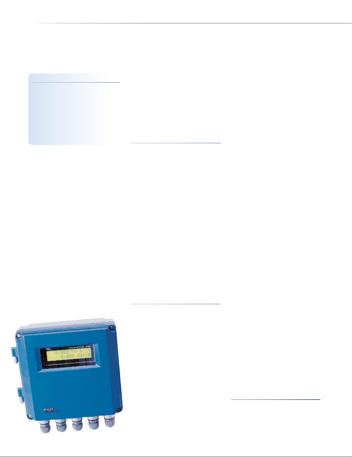
Fixed Transit-Time Flow Meter System
Ultrasonic Flow Meters Fuji Time Delta S
The Time Delta S is a xed ultrasonic ow meter based on the transit-time measurement
method for measuring ow rates of relatively clean homogeneous liquids utilizing clamp-
Key Features
• Dynamic ow correction
• Simple conguration
• Digital outputs
• Enhanced anti-bubble measurement
technology (ABM)
• Rugged and reliable
• Maintenance free
Information subject to change without notice. Prices in USD.
on sensors. Thanks to microprocessor-based electronics, the ow meter can be easily
congured from the front keyboard to particular applications. The Time Delta S is ideally
suited for liquid ow measurement for pipe diameters from 0.50 to 235 inches. Systems are
composed of a converter and sensor set. Applications include ow measurement of any
uid through which an ultrasonic signal may be transmitted, including those of unknown
sound velocities. The ow meter is a compact and lightweight instrument incorporating
the latest electronics and high speed digital signal processing technologies (32 bit MPU),
resulting in high performance and easy operation.
Features
• Dynamic flow correction – system
develops characteristic proles to correct
for optimal ow rates across the velocity
range
• Simple configuration – complete setup
from front keyboard and menu driven
software interface
• Digital outputs – 2 outputs may be
congured for totalizer pulse, ow switch,
range limiting, overow, memory alarm,
and abnormal signal condition
• Enhanced anti-bubble measurement
technology (ABM) – removes the effect of
entrapped and suspended ow bubbles
• Rugged and reliable – NEMA-6 (IP67)
enclosure makes Time Delta S well suited
to most industrial environments
• Maintenance free – no moving parts
provides long-term reliable operation
• High accuracy – ±0.5% to ±1.0% of
velocity typical on calibrated system
Performance Specications
for the Converter
Fluid Conditions
Measured fluid
(water, sea water, hydrocarbons or uid
of unknown sound velocity) capable of
ultrasonic wave propagation
Fluid turbidity 10000 deg. (mg/l) or less
State of flow Axis-symmetric ow in pipe
totally lled with uid
Fluid temperature Standard Temperature
Sensor: -40 to 212°F (-40 to 100°C).
High-Temperature Sensor: -40 to 390°F
(-40 to 200°C)
Velocity range 0.06 to 105 ft/sec (0.018 to
32 m/sec) bi-directional ow
Piping Conditions
Pipe material
cast iron, copper, pvc, aluminum, ductile
iron, asbestos, frp, peek, pvdf, acrylic and
other. If other is selected, pipe materials
Homogeneous liquids
Carbon steel, stainless steel,
with a sonic velocity range of 3280 to
12136 ft/sec (1000 to 3700 m/sec) can
be selected via the keypad (sonic velocity
information for several pipe materials is
included in the Operator Manual)
Pipe size Small pipe range detector: 0.50
to 4.0 in (13 to 100mm), 2 to 16 in (50 to
400mm). Universal pipe range detector: 8
to 48 in (200 to 1200mm). Large pipe range
detector: 8 to 235 in (200 to 6000mm)
Lining material Tar, epoxy, mortar, rubber,
Teon, Pyrex glass, other, or none. If other
is selected, liner materials with a sonic
velocity range of 3280 to 12136 ft/sec
(1000 to 3700 m/sec) can be selected via
the keypad. (Sonic velocity information for
several liner materials is included in the
Operator Manual.)
Fluid type Water, sea water or other. If other
is selected, a sonic velocity range of 1640
to 8200 ft/sec (500 to 2500 m/sec) can be
selected via the keypad. (Sonic velocity
information for several uids is included in
the Operator Manual.)
Measurement Accuracy
Accuracy
Linearity 0.1% of scale
Repeatability 0.5% or better
±0.5% of velocity for velocities
>1.0 ft/sec. typical on calibrated system;
±1.5% to ±2.0% of velocity for velocities
<1.0 ft/sec. typical on calibrated system.
(Calibrated system conditions include a
minimum of 10 inner pipe diameters of
upstream straight pipe run and a minimum
of 5 inner pipe diameters of downstream
pipe run. Longer runs may be necessary
due to pipe configurations.)
Physical Specications
for the Converter
Ambient temperature -10 to 140°F (-23.0
to 60.0°C)
Ambient humidity less than 90% RH
Enclosure Copper aluminum alloy, coated
with epoxy paint (blue/gray color)
082106
Page 2

Environmental rating NEMA-6 (IP67)
Dimensions 8.65H x 9.05W x 3.75D in.
(220 x 230 x 95 mm)
Weight 9.9 lbs. (4.5kg)
Functional Specications
for the Converter
Power supply 100 to 240V AC ±10%, 50/60
Hz. Optional 20 to 30V DC
Power consumption Approx. 20 VA
LCD display 2 line, 16 character per line,
4.0W x 1.0H in. (102 x 25mm), high
resolution Back-Lit LCD
Keypad 20 keys, tactile feedback
Power failure backup System data stored
in non-volatile memory
Response time 0.5 sec. or less
Analog output signal 4 to 20mA DC
(isolated), max. load resistance 1K Output
can be congured to hold last value, force
high, force low or force zero during fault
condition, keypad selectable
Transmit output voltage X1, X2, X4 and X8
transmit voltage, keypad selectable
Alarm output signals Two open-collector
digital transistor outputs (max., 30V DC,
200mA)
Analog output check Analog output values
of -20% to +120% can be forced onto
the analog loop via keypad for testing
purposes
Alarm output function Open collector
digital alarm outputs independently
congurable from keypad for the following.
Not Used: No output. Signal Error: ON
at abnormal measurement. Flow SW
high: ON when ow rate exceeds high
limit. Flow SW low: ON when ow rate
falls below low limit. F: Total alarm: ON
when ow total exceeds forward integral
switch. R: Total alarm: ON when ow total
exceeds reverse integral switch. F: Total
overow: ON when forward integral value
overows. R: Total overow: ON when
reverse integral value overows. R: Flow
direction: ON when reverse ow direction
is detected. F: Total Pulse: Forward ow
integral pulse. R: Total Pulse: Reverse ow
integral pulse (Note: maximum totalizer
pulse = 5 pulses/sec. Minimum totalizer
pulse = 1 pulse/day. Totalizer pulse width
50 msec or 100 msec, keypad selectable)
Communications Option RS-232 port
standard
Display language English or Japanese
(Katakana)
Measurement Display Screen
System units English or Metric, keypad
selectable
LCD display Congurable from keypad to
display ow rate and one of the following:
forward totalizer value, reverse totalizer
value, totalizer difference value, forward
totalizer pulse count, reverse totalizer
pulse count, ow velocity (ft/sec or m/sec)
and output range %
Display Display of forward or reverse
totalized ow, keypad selectable—
maximum 9 digits, with rollover cycle
counter
Totalizer English System Units: gal, Kgal,
ft3, Kft3, Mft3, Mbbl, Kbbl, acre-ft (gal =
U.S. gallons). Metric System Units: ml, l,
m3, Km3, Mm3, Mbbl, bbl, Kbbl
Ultrasonic Flow Meters Fuji Time Delta S
We attempt to provide you with complete information in this catalog. Because of the specific nature
of ultrasonic technology, we strongly recommend you contact us regarding application and availability
before placing your order.
Ordering Information
Included in standard delivery: converter, manual
FLVS12 Time Delta S xed transit-time ow meter converter, AC power input $ 2,650
FLVS42 Time Delta S xed transit-time ow meter converter, DC power input 3,250
Accessories
Each detector kit includes: Detector unit, 16 ft. signal cable, mounting straps, 3.5 oz tube of sonic coupling compound
Description Pipe diameter range Temperature range
FLD22 Small diameter sensor (2 MHz) 0.50 to 4.0 in -40 to 212°F $ 1,150
FLW12 Small diameter sensor (2 MHz) 2.0 to 16.0 in -40 to 212°F 1,150
FLW41 Universal sensor (1 MHz) 8.0 to 48.0 in -40 to 212°F 950
FLW50 Large diameter sensor (0.5 MHz) 8.0 to 235.0 in -40 to 212°F 2,500
FLD32 High-temperature sensor (2 MHz) 2.0 to 16.0 in -40 to 390°F 3,500
TKUSTTNIST Calibration, NIST traceable (5 pt.) 450
TKUSTTPTG FS-200 Ultrasonic thickness gauge 1,200
TKUSTTSG Sonic coupling compound 15
TKUSTTSGN Sonic coupling compound, silicone-free 35
TKUSTTPCSR Pipe tape measure 30
TKUSTTPLSS Line isolator/conditioner 359.95
TKUSTTRG58 Signal cable, 50 ohm (16 ft min) 2.50/ft.
Information subject to change without notice. Prices in USD.
052208
Page 3

Time Delta S
Specications (continued)
Ultrasonic Flow Meters Fuji Time Delta S
Flow rate English System Units: gal/sec,
gal/min, gal/hr, gal/day, ft3/sec, ft3/min, ft3/
hr, Mft3/day, bbl/sec, bbl/min, bbl/hr, and
Mbbl/day (Note: gal refers to U.S. gallons;
bottom line of LCD display configurable
from keypad). Metric System Units: l/sec,
l/min, l/hr, Ml/day, m3/sec, m3/min, m3/hr,
Mm3/day, bbl/sec, bbl/min, bbl/hr, and
Mbbl/day (Note: gal refers to U.S. gallons;
bottom line of LCD display configurable
from keypad)
Display Maximum 8-digit display of ow
velocity and rate with ow direction,
keypad selectable (Note: bottom line of
LCD display configurable from keypad)
Decimal point position Instantaneous ow
rate is keypad selectable for the following:
00000000, 0000000.0, 000000.00,
00000.000, 0000.0000, 000.00000,
00.000000 and 0.0000000 (Note: bottom
FLV Converter
line of LCD display configurable from
keypad)
Test mode Simulated ow values can be
entered directly from the keypad for bench
testing alarms, ow switches, totalizers,
and the analog output
Damping 0 to 99 sec. (time constant),
keypad selectable
Low flow cutoff 0 to 16.0 ft/sec (0 to 5.0
m/sec), keypad selectable
Zero setting Zero Point Adjust: used when
the ow can be stopped; zero point is
manually set. Zero Point Clear: used when
ow cannot be stopped; automatically sets
zero point, keypad selectable
Analog output cal 4 mA and 20 mA (zero
and span), keypad selectable
Analog output check Analog output values
of -20% to +120% can be forced onto the
analog loop via keypad for testing purposes
Detector Models FLW and FLD
Mounting method V or Z method mounted
to outside of pipe by means of steel bands,
nylon belts or steel wire
Straight pipe length Upstream side—10d
or more; downstream side—5d or more
(d = inside pipe diameter)
Signal cable RG-58 or RG-58A/U, 50 ohm
coaxial cable
Cable length Standard length 16 ft.,
maximum length 1000 ft. (300m)
Connection Converter: Internal screw.
Detector Models FLW: internal terminal
screw, strain-relieved, water-proofed.
Detector Models FLD: BNC connector
(female)
Pipe diameter range FLD22 (Small diam.
pipe range): 0.50 to 4.0 in. (13 to 100mm).
FLW12 (Small diam. pipe range): 2.0 to 16
in. (50 to 400mm). FLW41 (Universal pipe
range): 8.0 to 48 in. (200 to 1200mm).
FLW50 (Large diameter pipe range): 8.0
to 235 in. (200 to 6000mm). FLD32 (HighTemperature detector): 2.0 to 16 in. (50 to
400mm)
Operating temperature range FLD22,
FLW12, FLW41, FLW50: -40 to 212°F (-40
to 100°C). FLD32 (High-Temperature): -40
to 390°F (-40 to 200°C)
Ambient temperature range All detector
models: -4.0 to 140 °F (-20 to 60°C)
Ambient humidity All detector models: less
than 100% RH
Environmental rating FLW Models: NEMA
6 (IP67). FLD22/FLD32 Models: NEMA3
(IP52)
Material FLD22: High impact plastic
housing, aluminum alloy/high impact
plastic mounting bracket. FLD32: Stainless
steel housing, aluminum alloy/high impact
plastic mounting bracket. FLW12, FLW41,
FLW50: Polyurethane/stainless steel cover
plate. FLW12, FLW41, FLW50, FLD22:
Epoxy resin crystal wedge. FLD32:
Stainless steel crystal wedge
Dimension (WxHxD)/weight FLD22:
12.50 x 2.08 x 1.40 in./2.2 lbs. (540 x
53 x 36mm/1 kg). FLW12, FLW41 (each
transducer): 2.83 x 2.36 x 1.57 in./0.9 lbs.
(72 x 60 x 40mm/0.4 kg). FLW50 (each
transducer): 4.10 x 3.66 x 2.44 in./3.0
lbs. (104 x 93 x 62mm1.4 kg). FLD32 (rail
assembly including transducers): 20.86
x 2.05 x 1.30 in./3.53 lbs. (530 x 52 x
33mm/1.6 kg)
Information subject to change without notice. Prices in USD.
082106
Page 4

FLD32 High-Temperature Sensor SetFLD22 Small Diameter Sensor Set
Ultrasonic Flow Meters Fuji Time Delta S
FLW12 Small Diameter Sensor Set
Information subject to change without notice. Prices in USD.
4-12
Page 5

Time Delta S
Specications (continued)
Ultrasonic Flow Meters Fuji Time Delta S
FLW41 Universal Sensor Set
FLW50 Large Diameter Sensor Set
Information subject to change without notice. Prices in USD.Information subject to change without notice. Prices in USD. 4-12
 Loading...