

Page 1
Temperature Controller
MICRO-CONTROLLER X
48 × 48 mm
DATA SHEET
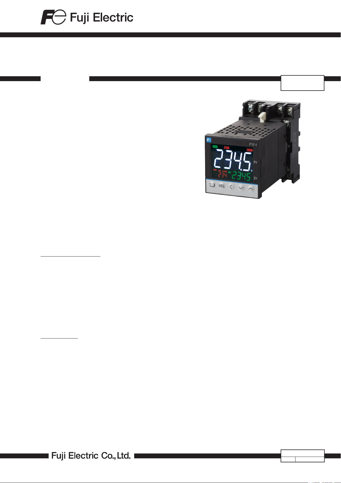
PXF4 socket type is a plug & socket type compact temperature controller developed as a successor to PXR4 socket
type. It has 48 × 48 mm front panel with color LCD, and an
85.7-mm deep body behind the panel.
FE ATU RE S
1. Enhanced control function
• Fast sampling speed of 50 ms
• Improved indication accuracy
• Freely configurable control cycle (100 ms to 99 s)
• Variety in control method
2. User-friendly interface
• Wide viewing angle LCD, high luminance white LED
backlight
• Digit select key for easier value-setting
3. Various functions
• 8 steps ramp/soak function
• Parameter loader interface
4. Universal input
• Accepts thermocouple, RTD, voltage, and current
SPECIFICATIONS
1. General specications
Power supply:
100 V (-15%) to 240 V (+10%) AC, 50/60 Hz;
24 V (±10%) DC/AC
Power consumption:
10 VA MAX. (100 to 240 V AC), 5 VA MAX. (24 V DC/AC)
Insulation resistance:
20 MΩ or more (at 500 V DC)
Withstand voltage:
Power source ↔ all terminals: 1500 V AC for 1 min
Relay contact output ↔ all terminals: 1500 V AC for 1 min
Between others 500 V AC for 1 min
2. Input section
2.1 Process value input
Number of input: 1
Input setting:
Programmable scale
Input signal: See Table 1
(Universal input: thermocouple, RTD, voltage, current)
Standard measurement range and input type:
See Table 1
Indication accuracy (at Ta = 23°C):
• Thermocouple input: ±0.5%FS ±1 digit ±1°C
*Exceptions:
Thermocouple B: 0 to 400°C: no accuracy assurance
Thermocouple R: 0 to 500°C: ±1%FS ±1 digit ±1°C
Thermocouples: -200 to -100°C: ±2°C ±1 digit
PXF4-2
SOCKET
• RT D in p u t : ±0. 8°C ±1 di g i t or ±0 . 2 % ±1 digit of indi c ated
value, whichever is larger
• mV input, voltage input, current input: ±0.3%FS ±1 digit
* Note that the sensor should be suciently warmed up
to secure the accuracy
Temperature eect on sensitivity:
±0.3%FS/10°C
Indication resolution:
See Table 1
Input sampling rate:
50 ms
Input impedance:
• Thermocouple, mV input: 1 MΩ or more
• Current input: 150 Ω or less (built-in diode)
• Voltage input: About 1 MΩ
Variation by signal source resistance:
• Thermocouple, mV input: ±0.3%FS ±1 digit per 100 Ω
• Voltage input: ±0.3%FS ±1 digit per 500 Ω
Allowable wiring resistance:
RTD: 10 Ω or less (per wire)
Allowable input voltage:
• DC voltage input: within ±35V
• Current input: within ±25 mA
• Thermocouple, RTD, mV input: within ±5 V
Noise reduction ratio:
• Normal mode: 40 dB (50/60 Hz)
• Common mode: 120 dB (50/60 Hz)
• Between input and power supply: ±1°C at 220 V AC,
50/60 Hz
Input correction:
(a) User adjustment: ±50%FS for each of zero and span
point
(b) Process value shift: ±10%FS
(c) Input lter: 0.0 to 120.0 s
(lter OFF if set at 0.0)
(d) Square root extraction: -0.1 to 105% (OFF if set to -0.1%)
EDS11-185a
Date Apr. 23, 2020
Page 2
PXF4-2
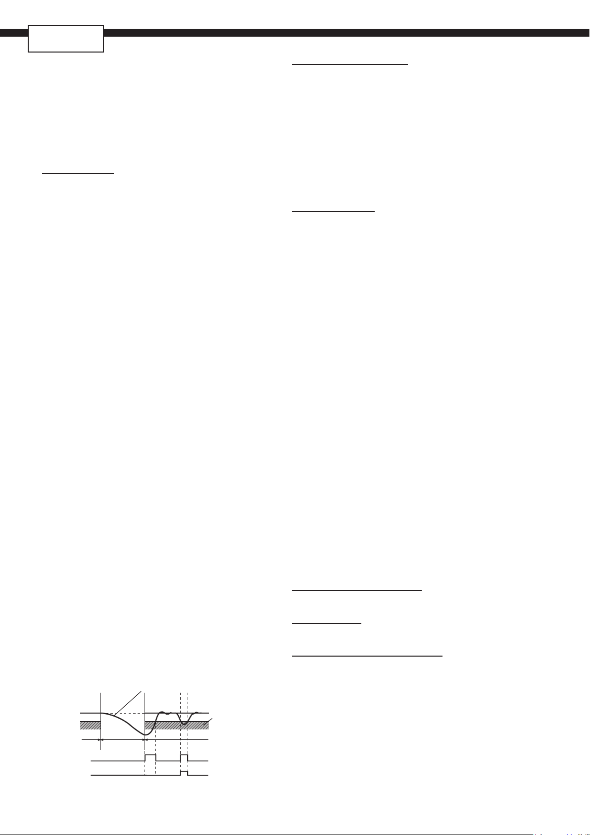
Lower limit alarm
(with hold)
PV (process value)
limit alarm is emitted
Lower limit alarm
SOCKET
Overrange, underrange:
Out of the range between -5% and 105% FS (accuracy
not guaranteed between -5 and 0, and between 100 and
105% FS)
*Exceptions:
• JPt, Pt, 0–10 V DC: out of the range between -2%
and 105% FS
• Thermocouple E: out of the range between -5% and
102% FS
4. Indication/setting section
4.1 Display unit
Type:
LCD (with backlight)
Indication contents:
Process value indication: 11-segment, 4-digit [white]
Setpoint indication: 11-segment, 4-digit [green]
Screen No. indication: 7-segment, 3-digit [orange]
Status indication: 23 indicator lamps
3. Output section
3.1 Control output
Number of points: 1
Type:
selected among (1) to (3) below
(1) Relay contact output (SPDT)
• Proportional cycle: 1 to 150 seconds
• Contact structure: SPDT (single pole double throw)
• Contact capacity: 250 V AC/30 V DC, 5 A (resistive
load)
• Mechanial life: 50 million operations MIN. (100
operations/min)
• Electrical life: 100,000 operations MIN. (rated load)
(2) SSR drive output
• Proportional cycle: 1 to 150 s
• ON voltage: 12 V DC (between 10.7 and 13.2V DC)
• OFF voltage: 0.5 V DC or lower
• Maximum current: 20 mA DC
• Load resistance: 600 Ω MIN.
(3) Current output (4 to 20 mA DC)
• Accuracy: ±5%FS
• Load resistance: 500 Ω MAX.
3.2 Alam output (option)
Number of outputs:
Relay contact output: Up to 2
Output specications:
Relay contact output
Contact structure: SPST (single pole single throw)
Contact capacity: 250 V AC/30 V DC, 1 A (resistive load)
Minimum ON/OFF current: 10 mA (5 V DC)
Mechanical life: 20 million operations MIN.
(100 operations/min)
Electrical life: 100,000 operations MIN. (rated load)
Alarm kind:
Absolute alarm, deviation alarm, zone alarm, upper and
lower limit, and hold function available for each kind of
alarms.
Alarm latch, Excitation/non-excitation selecting function
provided.
Output cycle:
100 ms
What is alarm with hold?
The alarm is not turned ON immediately even when the
process value is in the alarm band. It turns ON when it
goes out the alarm band and enters again.
Zone where lower
Power OFF
on on
off
off
Power ONPower ON
on
offoff
off
4.2 Setting section
Five embossed keys
5. Control functions
5.1 Control types
ON/OFF control
PID control
• PID parameters determination: Auto tuning
Fuzzy PID control
• PID parameters determination: Auto tuning
Self tuning control
PID2 control
• PID parameters determination: Auto tuning
5.2 Control parameters
• Proportional band (P): 0.0–999.9% (On/o control when
P=0)
• Integral time (I): 0 to 3200 s
Integral time control invalidated when
I = 0.
• Dierential time (D): 0.0 to 999.9 s
Dierential time control invalidated
when D = 0.
• Control cycle: 100 to 900 ms (in 100 ms), 1 to 99 s (in s)
• Anti-reset windup:
0 to 100% of measurement range
• Hysteresis band: 50% of measurement range
(available only during the on/o control)
5.3 Control mode
Mode type:
Auto, Manual
*In the manual mode on/o control, available MVs are
100% and 0%.
Mode switching:
• Auto↔Manual: Balanceless·bumpless
6. Data backup at power failure
On non-volatile memory
7. Self-diagnosis
Program error supervision by watchdog timer
8. Operation and storage conditions
Operating ambient temperature:
-10 to 50°C
Storage temperature:
-20 to 60°C
Operating/storage ambient humidity:
90%RH MAX. (no condensation)
Warm-up time:
30 min MIN
Vibration:
During transportation 9.8 m/s2 (1G) or less
Impact:
During transportation: 294 m/s2 (30G) or less
2
Page 3
9. Structure
Mounting method:
Panel ush mounting, DIN rail mounting
(DIN rail mounting requires the dedicated socket.)
External terminals:
8-pin or 11-pin socket, M3.5 screw terminals
*The socket is a separate order item.
Case:
• Material: ABS, PPO
• Flammability: equivalent to UL94V-0
• Color: Black
Protection structure:
• Panel front side: equivalent to IP66 and NEMA 4X
(When the panel is mounted using our genuine packing.
Not water-proof if mounted closely together.)
• Body (slits on top and bottom): equivalent to IP20
Dimensions:
48 (W) × 48 (H) × 85.7 (D) mm
Weight:
Approx. 200g
10. User customize function
Parameter mask function:
You can switch between show/hide of parameters.
Program (ramp/soak) function:
• Number of program patterns: 1 or 2
• 8 ramps and 8 soaks in total
User key:
You can assign the following functions to the user key:
auto/manual switching, standby on/o, etc.
11. Certication
• CSA
• UL, C-UL: expected date of certication: March 2019
12. EU Directive Compliance
LVD (2014/35/EU)
EN 61010 -1
EN 61010 -2-030
EMC (2014/30/EU)
EN 61326-1 (Table 2)
EN 55011 (Group 1 Class A)
EN 61000-3-2 (Class A)
EN 61000-3-3
RoHS (2011/65/EU)
EN 50581
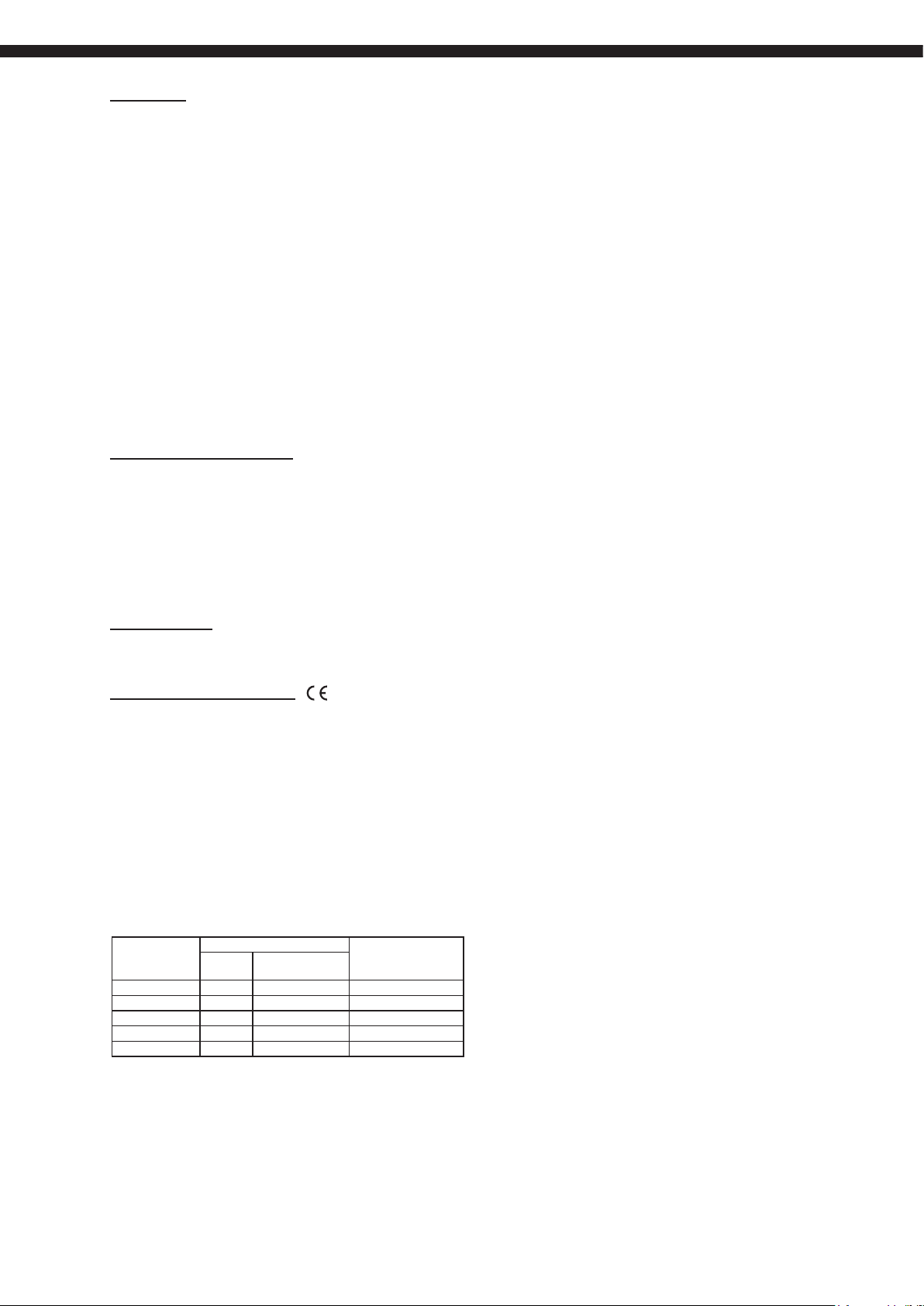
*The following table shows the dierence of outputs among
other micro-controller X series models.
SSR driving output Allowable load resis-
Voltage Maximum current
PXR3 DC15V 20mA 100 ~ 500 Ω
PXR4/5/7/9 DC24V 20mA 600 Ω or less
PXV3 DC5.5V 20mA 600 Ω or less
PXV/PXW/PXZ DC24V 20mA 600 Ω or less
PXF DC12V 20mA 500 Ω or less
tance for 4 to 20mA
DC output
3
Page 4

PXF4-2
SOCKET
Table 1 Measurement range
Input type Measurement range [°C] Minimum input increment [°C]
RTD JPt100 -199.9 to 600.0 150
Pt100 -200 to 850 150
Thermocouple J -100 to 1000 400
K -200 to 1300 400
R 0 to 1700 1700
B 0 to 1800 1800
S 0 to 1700 1700
T -199.9 to 400.0 399.9
E -200 to 800 800
L -100 to 850 950
N -200 to 1300 1500
PL-II 0 to 1300 1300
W 0 to 2300 2300
U -200 to 400.0 599.9
DC voltage 0–5 V DC
1–5 V DC
0–10 V DC
2–10 V DC
0–100 mV DC
DC current 0–20 mA DC
4–20 mA DC
-1999 to 9999
(Scaling range)
―
Notes:
1. When the temperature exceeds 1000°C, the decimal point does not appear on the screen.
2. Input signal, measurement range, and set value at the time of delivery are as follows:
Thermocouple K, Measurement range from 0 through 400°C, Set value 0°C.
Switching the input signal among thermocouple, RTD, current, and voltage is available by key operation on the front panel.
4
Page 5

CODE SYMBOLS
456 7 8
9 10 11 12 13
(mA input dose not require the resistor)
Standard type
PXF
-
2U
0Y 04
Digit
<Front panel size W × H>
4
48×48mm
<Input signal>
5
Universal input (Thermocouple/Volt, backwards compatible wiring)
Universal input (RTD/mA, backwards compatible wiring)
<Control output>
6
Relay contact (SPDT)
SSR drive output
Current output
<Terminal form>
7
Socket type
<Revision code>
8
<Alarm output>
9
None
2 points
<Power supply voltage>
10
100 to 240V AC
24 V AC/DC
11
12
13
Note1: Wiring compatible to previous PXZ, PXW, PXV and PXR socket controllers.
Specifications
Note
Note1
4
A
N
B
C
E
U
2
4
G
V
B
Y 0 0
SCOPE OF DELIVERY
• Controller × 1
• Instruction manual × 1
• Panel mounting frame × 1
• Watertight packing × 1
SEPARATE ORDER ITEMS
PC loader communication cable 1 ZZP*TQ501923C3
4 No alarm
4th code
G Two alarms
8-pin socket for DIN rail mounting (TP48X) 1 ZZP*PXF2-C100
8-pin socket for panel mounting (TP48SB) 1 ZZP*PXF2-C101
11-pin socket for DIN rail mounting (TP411X) 1 ZZP*PXF2-C102
11-pin socket for panel mounting (TP411SBA) 1 ZZP*PXF2-C103
Item Q`ty Ordering code
5
Page 6

48
Panel
PXF4-2
SOCKET
OUTLINE DIAGRAM (Unit : mm)
48
44.8
44.8
7.7
Panel thickness (t): 1 ≤ t ≤ 8
*If you connect the parameter loader cable to panel-mounted PXF,
the panel thickness should be: 1 ≤ t ≤ 4
1
71.5
85.7
78.2
92.4
44.8
Waterproof packinng
PANEL CUTOUT SIZE (Unit : mm)
Installing multiple controllers
63 or more
57
Mounting bracket
Side stick mounting
+0.5
0
45
48
+0.5
a
0
68 or more
+0.5
0
45
Number
of units
2 3 4 5 6
93 141 189 237 285a
+0.5
45
0
6
Page 7

TERMINAL ALLOCATION
Control output 1
Power supply
Alarm output
Control output 1
Thermocouple
RTD
CurrentVoltage
Thermocouple
RTD*
CurrentVoltage
: No insulation
8-pin socket (for the versions that have no alarm)
Relay
output
Current
output
Process value input
(When the 5th code is "A") (When the 5th code is "N")
–
+
Thermocouple
SSR drive
output
–
+
–
+
Universal input Universal input
A
B
B
1
RTD*
11-pin socket (for the versions that have two alarms)
–
+
SSR drive
output
–
+
Relay
output
Current
output
100 to 240V AC
50/60Hz*250/60Hz*
+
–
–
+
CurrentVoltage CurrentVoltage
B
B
A
3
*
RTD
+
–
1
*
Thermocouple
Power supply
100 to 240V AC
+
–
Common
Alarm output1
(AL1)
Alarm output2
(AL2)
24V DC/AC
–
+
24V DC/AC
3
*
2
Process value input
(When the 5th code is "A") (When the 5th code is "N")
Universal input
A
–
+
*1: The terminal layout diers from that of PXW4/PXZ4/PXV4.
B
B
–
+
1
+
–
B
B
A
3
*
Universal input
+
–
*2: Check the power supply voltage before installation.
*3: Terminal allocation is dierent from PXR4. A 250Ω shunt resistor is not required.
INSULATION BLOCK DIAGRAM
Power supply (100 to 240 V AC)
Control output 1 (relay contact)
Alarm output 1 and 2 (relay contact)
Power supply (24 V DC/AC)
Control output 1 (relay contact)
Alarm output 1 and 2 (relay contact)
Control output 1 (SSR drive, current, voltage)
Control output 1 (SSR drive, current, voltage)
Internal circuit
Process value input
Internal circuit
Process value input
50/60Hz*250/60Hz*
+
–
1
*
2
–
+
3
*
: Basic insulation (1500 V AC)
: Functional insulation (500 V AC)
7
Page 8

8-pin socket (for the versions that have no alarm)
PXF4-2
SOCKET
SOCKET OUTLINE DIAGRAM (Unit : mm)
ZZP*PXF2-C101 (for panel mounting) TP48SB
φ27
45
45
TERMINAL SCREW
M3.5×8
354 5 6
2 1 8 7
17
11-pin socket (for the versions that have two alarms)
ZZP*PXF2-C102 (for DIN rail mounting) TP411X
TERMINAL SCREW
M3.5×11
5
2-φ4.5
HOLE
87116
9
10
7. 8
50
4
70
3
1
2
4
31.2 MAX.
4.5
7
35.4
ZZP*PXF2-C100 (for DIN rail mounting) TP48X
TERMINAL SCREW
2-φ4.5
HOLE
M3.5×8
6
543
78 1 2
7. 8
50
40±0.2
704
2-φ4.5
MOUNTING HOLE
5.5
20.3 MAX.
ZZP*PXF2-C103 (for panel mounting) TP411SBA
φ27
45
45 4.5 6.216.3
TERMINAL SCREW
M3.5×11
5
6
4
25.6
3
111
2
35.4
78
9
10
7
40±0.2
2-φ4.5
MOUNTING HOLE
Information in this catalog is subject to change without notice.
Read the instruction manuals thoroughly before using the products.
www.fujielectric.com
Instrumentation & Sensors Planning Dept.
Gate City Ohsaki, East Tower, 11-2, Osaki 1-chome, Shinagawa-ku, Tokyo 141-0032, japan
Phone: +81-3-5435-7021 Fax: +81-3-5435-7475
www.fujielectric.com/products/instruments/
Printed in Japan
 Loading...