

Page 1

Instruction Manual
Program Controller X
Type : PVX
INP–TN1PVXa-E
Page 2
PREFACE
This User’s Manual is intended for providing the reader with essential information on Program
Controller X, type PVX, hoping that the unit can be properly operated to the benefit of the user.
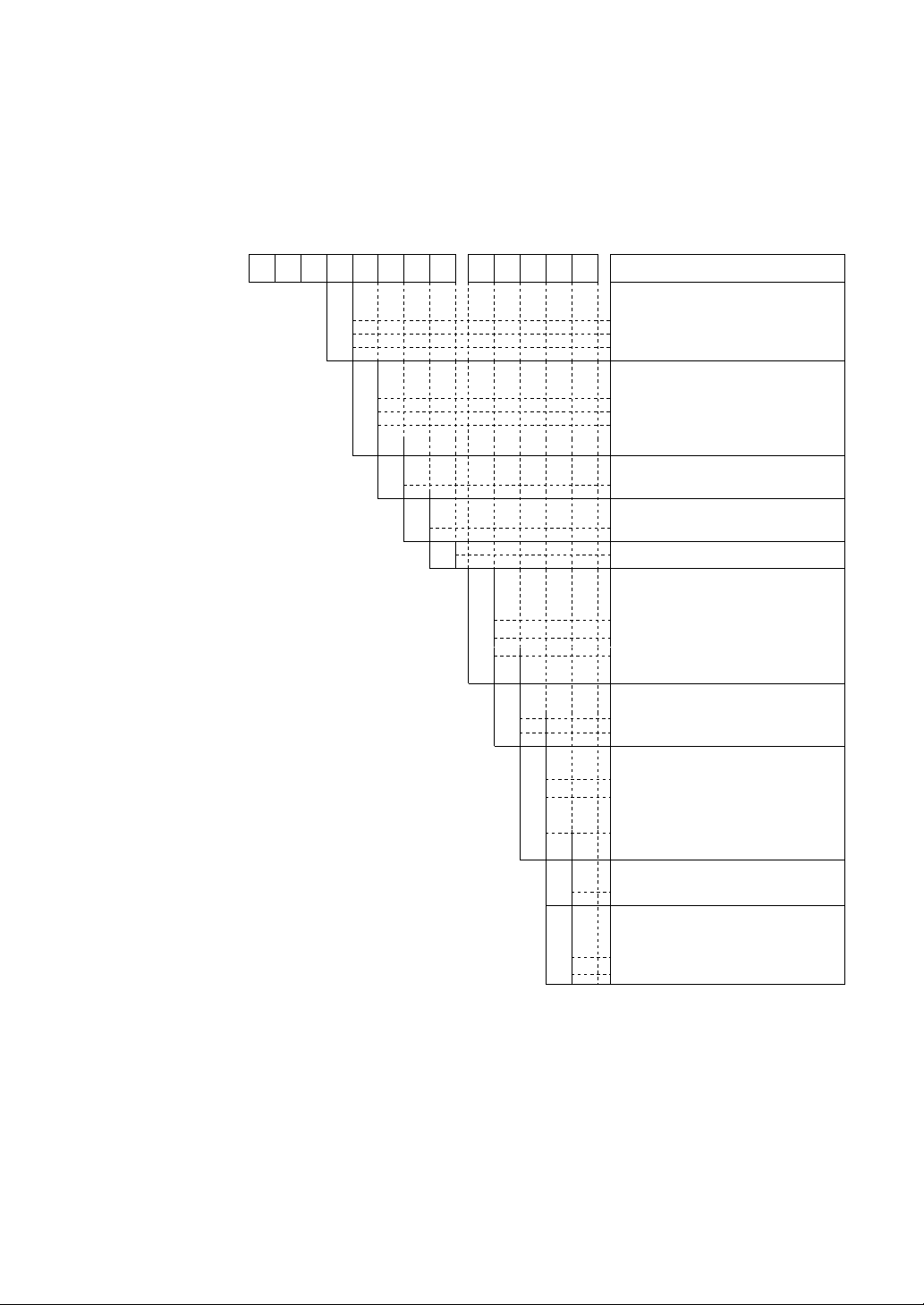
■ Code Symbols
12345678 910111213
PVX 1
1
2
3
C
P
D
T
S
1
Control output
Relay contact output
SSR/SSC drive output
DC4 to 20mA output
Digital input
External command input (4 points)
Pattern select input (4 points)
External command input + Pattern
select input
Time signal output 1 to 4
Provided
Status output (Operating profile output)
Provided
Modification No.
Extended digital output (Open
collector output: 2 points)
Y
T
A
Not provided
To be used as time signal (TS5, 6)
To be used as alarm (ALM3, 4)
Contents
Y
R
0
1
2
• Scope of supply
Program controller, panel fixtures, and
user’s manual
Y
E
J
■ List of Abbreviations frequently used in this Manual:
CLR: Clear
DSP: Display
PTN: Pattern
SEL: Select
ENT: Enter
HLD: Hold
SFT: Shift
REST: Reset
ALM: Alarm
MAN: Manual
PTN: Pattern
PV: Processing Variable
Loader interface
Not provided
Provided
Auxiliary signal output
Not provided
Voltage output:
1 point
Voltage output:
2 points
Communication facility
Not provided
User’s manual, instructions and
setting
English version
Japanese version
Note)
1 to 5 VDC at
the shipment
from factory
DV: Deviation
SV: Set Value
TM: Time
MV: Manipulating Value
A/M: Auto/Manual
– i –
Page 3

CONTENTS
PREFACE ................................................................................................................ i
Code Symbols ......................................................................................................................... i
List of Abbreviations frequently used in this Manual:............................................................ i
Overview ................................................................................................................................. iv
Explanation of Front Panel......................................................................................................v
Explanation of Keys and How to Use Them ........................................................................... v
SECTION 1 BEFORE STARTING OPERATION .................................................... 1-1
1. Changing Displays on Operating Screen ......................................................................... 1-1
2. Operation.......................................................................................................................... 1-1
3. Parameter Setting Overview ............................................................................................ 1-3
SECTION 2 PROGRAMMING.................................................................................. 2-1
1. Parameter Structure and Parameter Calling Method........................................................ 2-1
2. Program Pattern Setting (Program Pattern Setting Channel) ........................................... 2-2
2.1 Program pattern structure .......................................................................................................................... 2-2
2.2 Pattern Setting [Setting of a set value (SV) and time] .............................................................................. 2-4
2.3 Setting of supplementary functions ........................................................................................................... 2-6
2.3.1 Setting of PID group......................................................................................................................... 2-6
2.3.2 Setting of alarm values 1 to 4........................................................................................................... 2-7
2.3.3 Setting of time signal........................................................................................................................ 2-8
2.3.4 Guarantee soak (Waiting for PV to follow) ..................................................................................... 2-9
2.3.5 PV Start (Allowing the program to start from the current PV)........................................................ 2-10
2.3.6 Cyclic Operation (Repetitious execution of a pattern)..................................................................... 2-11
2.3.7 Pattern-Link Operation (Successive pattern execution)................................................................... 2-12
2.4 Editing Program Pattern ............................................................................................................................ 2-13
2.4.1 Segment insertion (a new segment is created between segments) ................................................... 2-13
2.4.2 Segment erasure (a segment in a pattern is erased).......................................................................... 2-13
2.4.3 Copying a pattern ............................................................................................................................. 2-14
2.4.4 Pattern erasure .................................................................................................................................. 2-15
2.4.5 Erasure of all patterns....................................................................................................................... 2-15
2.4.6 Change of running program ............................................................................................................. 2-16
3. Setting of PID Group (PID Setting Channel)................................................................... 2-17
3.1 Structure of PID Setting Channel.............................................................................................................. 2-17
3.2 Setting of each parameter .......................................................................................................................... 2-18
3.2.1 Setting of proportional zone (P), integration time (I), and differentiation time (D) ........................ 2-20
3.2.2 Setting of blind zone......................................................................................................................... 2-20
3.2.3 Manipulating value (MV) upper and lower limits............................................................................ 2-21
3.2.4 Reversing specification .................................................................................................................... 2-21
3.2.5 Non-linear gain................................................................................................................................. 2-22
3.2.6 Integration break point ..................................................................................................................... 2-22
3.2.7 Manual reset ..................................................................................................................................... 2-23
SECTION 3 SETTING UP .. Start-up and specification changes .............................. 3-1
1. Structure of System Setup Channel ................................................................................. 3-1
2. Setting of Each Parameter ................................................................................................ 3-3
2.1 Setting of PV input type and input range .................................................................................................. 3-3
2.2 Setting of PV display unit (°C or°F) and 0.1°C (°F) notation
(for thermocouple or resistance bulb) ....................................................................................................... 3-4
2.3 Setting of full scale and base scale in the engineering unit notation
(for DC voltage and current input) ............................................................................................................ 3-5
2.4 PV filter (reducing the wander of PV arising from noise) ........................................................................ 3-6
2.5 PV shift (shifting zero point of PV) .......................................................................................................... 3-6
2.6 Start mode (defining a startup mode at resumption of power supply) ...................................................... 3-7
– ii –
Page 4

2.7 MV proportional period (for relay-drive or SSR/SSC-drive output) ........................................................ 3-7
2.8 Setting of preset MV (defining MV in the reset state) .............................................................................. 3-8
2.9 Burnout MV setting (defining MV at the burnout) ................................................................................... 3-8
2.10 Setting of alarm type ................................................................................................................................. 3-9
2.11 AO output type (sending PV, SV, and MV to auxiliary analog output) ................................................... 3-10
2.12 AO range and scale (scaling auxiliary analog output) .............................................................................. 3-11
2.13 Time unit (switching from hr:min to min:sec or vice versa) ..................................................................... 3-11
2.14 Setting of time display type (switching from remaining time to lapsed time or vice versa) ..................... 3-12
2.15 END signal output time ............................................................................................................................. 3-12
2.16 Guarantee soak waiting allowance and setting of max. wait time ............................................................ 3-13
2.17 Setting of T-link station number ............................................................................................................... 3-13
3. Various Operating Methods ............................................................................................. 3-14
3.1 In this unit the operation mode (operating profile) can be changed over as illustrated below.................. 3-14
3.2 Auto tuning................................................................................................................................................ 3-15
3.3 Fixed value operation ................................................................................................................................ 3-16
3.4 Manual operation....................................................................................................................................... 3-17
3.5 Remote operation (Option)
(for the entry of external commands and selected pattern and the output of status) ................................. 3-17
SECTION 4 ADVANCED USAGE ........................................................................... 4-1
1. Structure of expert parameter channel ............................................................................. 4-1
2. Setting of each parameter................................................................................................. 4-2
2.1 Set value (SV) upper and lower limits ...................................................................................................... 4-2
2.2 Manipulating value (MV) variation limit.................................................................................................. 4-2
2.3 Setting of alarm 1 to 4 hysteresis allowances............................................................................................ 4-3
2.4 DV differentiate specification D operation of PID is differentiated for DV............................................. 4-3
2.5 AT SV mode
Auto tuning in the low PV type ................................................................................................................. 4-4
2.6 AT PID mode
Obtaining PI control parameter ................................................................................................................. 4-4
2.7 Transmission write protect
The SV change via transmission is inhibited. ........................................................................................... 4-5
SECTION 5 INSTALLATION AND WIRING ......................................................... 5-1
1. Outline Diagrams ............................................................................................................. 5-1
2. Installation........................................................................................................................ 5-1
2.1 Appropriate locations for installation........................................................................................................ 5-1
2.2 How to install the unit ............................................................................................................................... 5-2
3. Wiring .............................................................................................................................. 5-2
3.1 Cautions for wiring.................................................................................................................................... 5-2
3.2 Noise control measures ............................................................................................................................. 5-2
3.3 For connection of load circuit ................................................................................................................... 5-3
3.4 Wiring for the input 1 to 5 VDC ............................................................................................................... 5-3
3.5 External wiring diagram............................................................................................................................ 5-3
SECTION 6 APPENDIX ............................................................................................ 6-1
1. Specifications ................................................................................................................... 6-1
2. [Program Pattern Preparation Form] ................................................................................ 6-3
3. Parameter List .................................................................................................................. 6-4
– iii –
Page 5
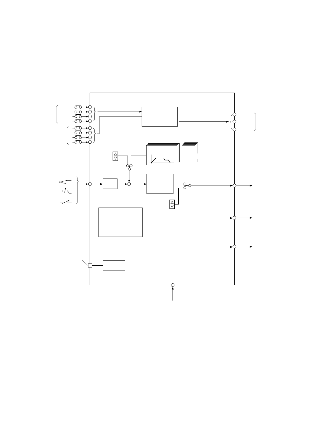
■ Overview
This Program Controller, 96 mm × 96 mm in the front-view size, incorporates a microprocessor to
perform the programmed control for Processing variables, such as temperature, humidity, pressure,
flow rate, rotating speed.
Reset
External
command
Pattern select input
Run
Hold
input
Advance
Sensor input
Full multi-input
Loader interface
Conforming to (RS-232C)
(Option)
DI
•External command
input
•Pattern select input
Program
SV
•Status output
9 patterns 9 sets
Program setting
20 segment
PID with autotuning
•Auxiliary analog
output
1/2 points
(PV/SV/MV)
•Time signal output
4 points (+2 points) See Note.
•Alarm output
2 points (+2 points) See Note.
3
2
2
2
1
2
0
2
AI
Fixed SV
Fixed
(FIX)
PV
Filter
•Guarantee soak function
•PV start function
•Pattern concatenate
function
•Pattern repeat function
(99 times max.)
Communication facility
Reset
Run/Hold
End
Control
parameter
Such as PID
Auto
Man
Manual operation
3 points
MV
Reset
Run/Hold
End
Control output
AO
(Option)
DO
Status
output
– iv –
Power supply
100 to 240 VAC
Note: (+2 points) denotes that either time
signal or alarm output may be
supplemented as an option.
Page 6
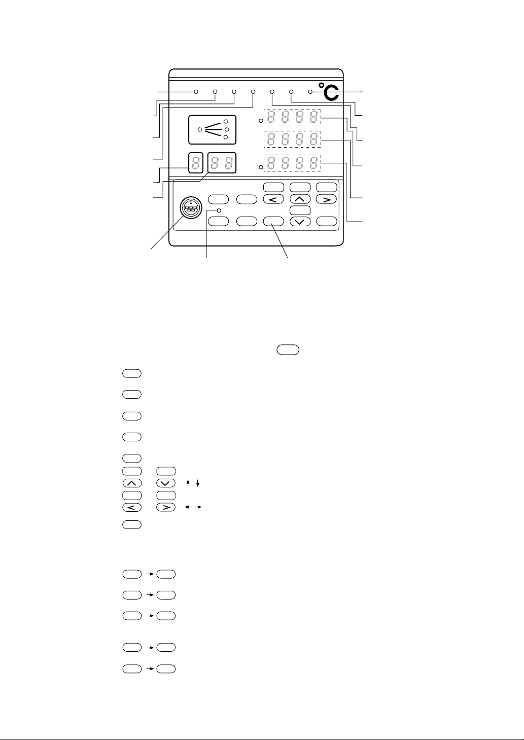
■ Explanation of Front Panel
is selected
(See the description below)
SFT
Lights while the program
operation is running
Lights while the program
operation is being held
Lights when the program
operation is ended
Lights when manual
control mode is applied
Program number display
Segment number display
Program loader connector
■ Explanation of Keys and How to Use Them
Keys are provided in two lines: the upper line and lower line.
To use a function in the lower line, depress an appropriate key as it is.
To use a function in the upper line, depress
CLR
DSP
FIX
PTN
A/M
SEL
AT
INS
END
ENT
RUN HLD
REST
SFT
SFT DSP
SFT PTN
SFT SEL
SFT
SFT
RUN HLD END MAN ALM TS C
Lights while the control
output is ON
PROFILE
PTN SEG
LOADER CLR FIX
DSP
PTN
SFT
SEL INS ENT
DV
TM
MV
PV
SV
REST
ATA/M
HLD
ADVRUN
COPY
Lights when an event occurs
due to time signal
Lights when an alarm is
generated
Process variable display
(Deviation display while
LED indicator is lighted)
Set value display or
parameter name display
Time display. Manipulating
value display or parameter set
value display when LED
indicator is lighted.
Lights when upper key
Program set key
key once and a key to be used.
: To be used for changing the display.
: To be used for selecting a program pattern.
: To be used for selecting a parameter.
: To be used for inserting a program pattern.
: To be used for data setting and entry.
: Cursor keys to be used for selecting a parameter and for changing a data value.
ADV
: Cursor keys to be used for selecting a parameter and for selecting a column.
: To be depressed when a key function in the upper line is used. When this key is depressed, the
LED embedded in this key will light by toggle action, thus indicating that a key in the upper line
has been selected.
By depressing the key once again, the LED will go off, indicating that a key function in the
lower line has been selected.
CLR
: To be used for erasing a program pattern.
FIX
: To be used when entering the fixed-value operating mode.
A/M
: To be used when switching from AUTO to MANUAL, or vice versa. The AUTO
mode and the MANUAL mode are alternately changed over by depressing the key
with a toggle mechanism.
AT
INS
: To be used when starting the auto tuning.
COPY
: To be used when copying a program pattern.
ENT
– v –
Page 7
SECTION 1 BEFORE STARTING OPERATION
Devia-
Operation starts from segment 1.
Set value
Set value
1. Changing Displays on Operating Screen
Various operation displays can be changed by depressing
RUN ADV
HLD
tion
DSP
COPYA/M
ENT
PV
SV
TM
Manipulating
value
DSP
DSP
RUN ENDHLD MAN CALM TS
PV
DV
SV
TM
MV
LOADER
CLR FIX
DSP PTN
SFT SEL INS
REST
Alarm 1 to 2 status Time signal status Time signal status
DSP
2. Operation
(1) Starting the operation
DSP
PV
SV
MV
SFT
key.
DSP
DSPDSPSFT
RUN
PV
No. of cycles
RUN
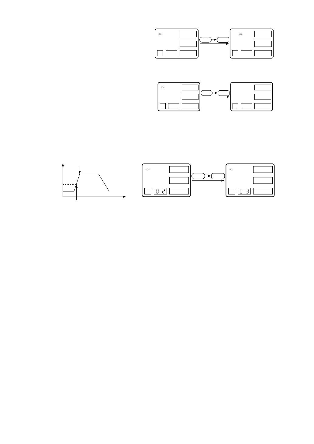
(2) Starting the operation at the current temperature (PV start function)
Present value
Operation starts at the present
temperature.
This operation is performed only when YES has been assigned to PV Start (PVST) in the program
pattern mode.
If NO is assigned in the setting, the normal operation (1) is performed.
Time
Time
(Reset state) (Running state)
RUN
SFT
RUN
(Reset state) (Running state)
1-1
Page 8
(3) Suspending the operation
Present position
This is an instance when the program
RUN
SFT
HLD
running operation is temporarily held
while operating the unit.
(Running state) (Holding state)
To resume the program running operation, follow the step for (1) Starting the operation.
HLD
(4) Ending the operation
Resetting is performed in the running
state or in the holding state.
(5) Advancing a segment while in the
running operation
A next segment is forcedly advanced while in the running operation.
One segment is advanced
Set value
for operation.
Time
RUN
SFT
Rest
(Running or Holding state) (Reset state)
RUN
SFT
(Running state)
RUN
Adv
(Running state)
1-2
Page 9
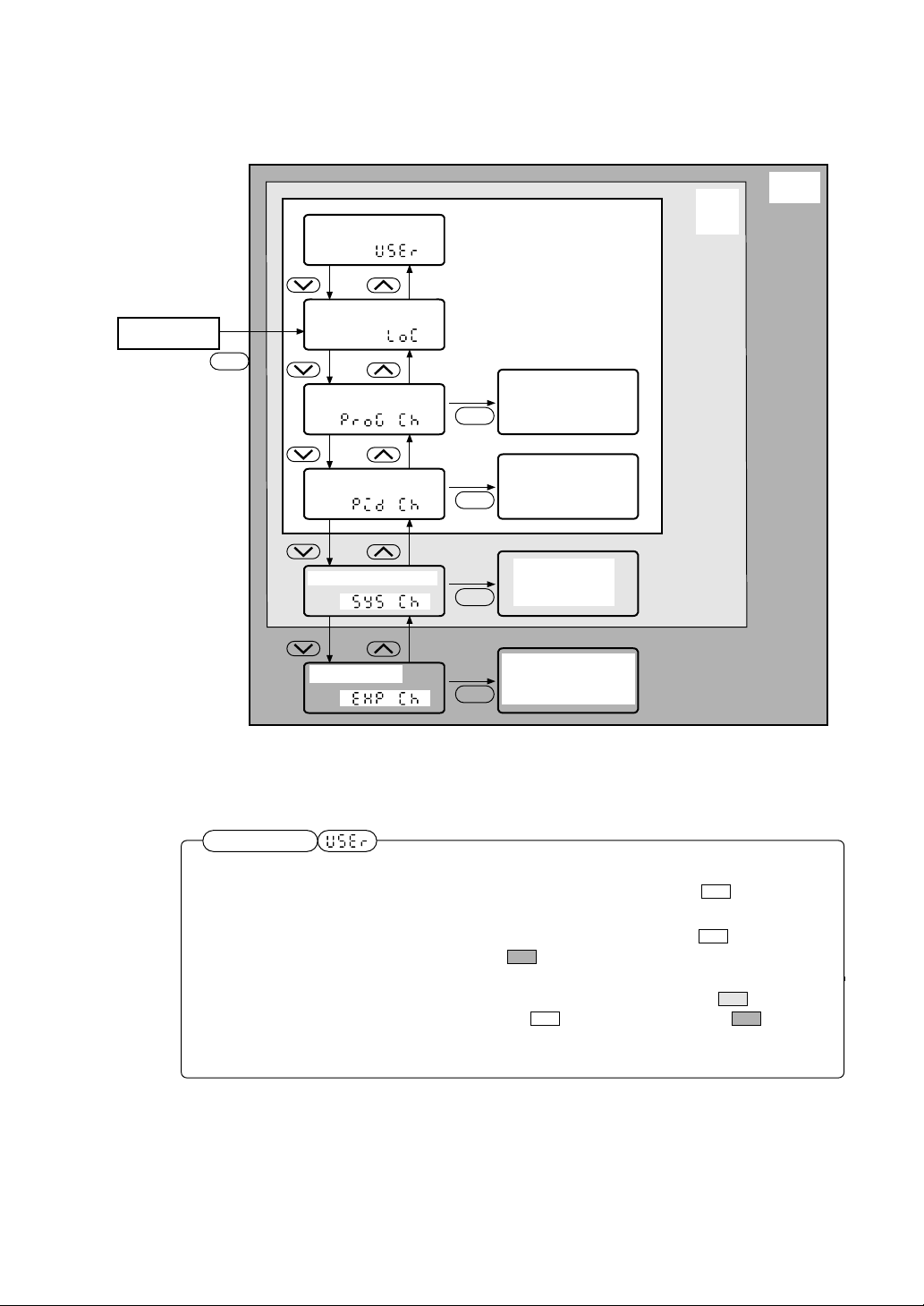
3. Parameter Setting Overview
The unit parameter structure and parameter calling methods are shown below.
User level
Keep on pressing for 3 seconds.
Operating status
display
SEL
Setting lock
Program pattern set
channel
Parameter for setting
a program pattern
(see section 2)
SEL
End user
0
Set
maker
1
Expert
2
PID channel
System setup channel
Expert channel
Parameter for setting
a PID group
(see section 2)
SEL
Parameter to be
set for operation
SEL
SEL
(see section 3)
Parameter to be set
for more advanced use
(see section 4)
For details of paramters in each channel, see the Parameter List at the end of this Manual.
User level
Parameter display range may be changed by setting the user level.
0: End user
Displays parameters in the unshadowed area . The displayed
parameters are needed for program pattern setting.
1: Set maker
Displays parameters in the unshadowed area plus darkshadowed area . The displayed parameters are needed for
setting up the unit.
2: Expert
Displays parameters in the light-shadowed area in addition
to the unshadowed and dark-shadowed areas . The
displayed parameters are needed for more advanced use of this
unit.
1-3
Page 10
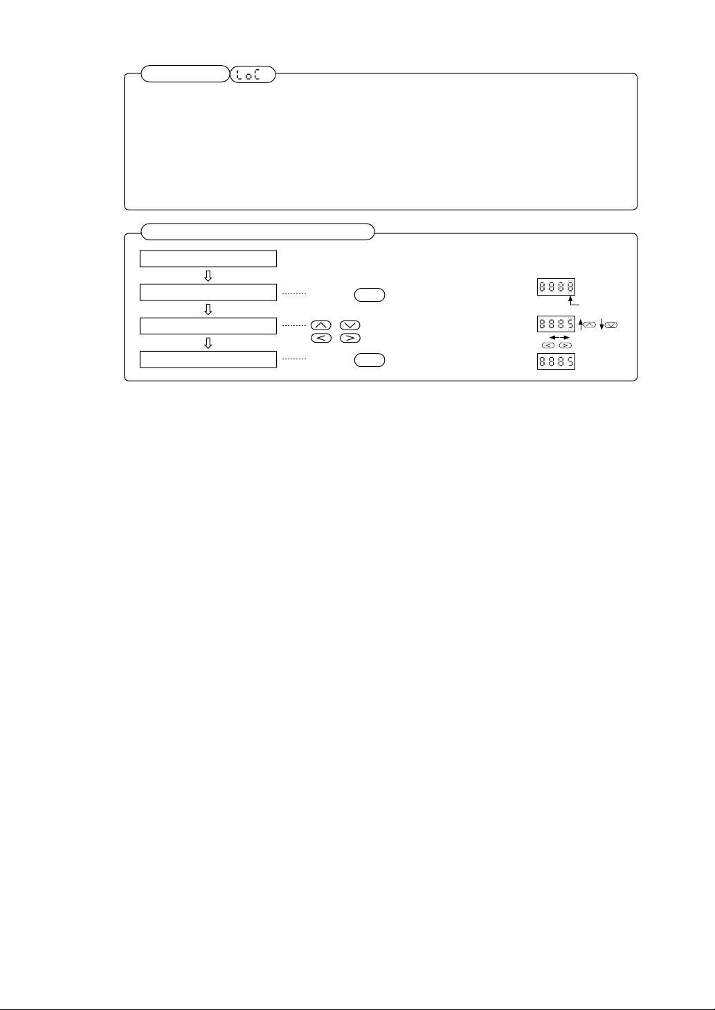
Setting lock
This is a setting lock parameter for prevention of an erroneous setting.
0: Total release
1: Operation release
Enables the setting of all parameters, with no setting locked.
With the setting locked, no change can be made for parameter
values. Permits only the running operation and reset operation.
2: Total lock
All the setting operations are locked. Inhibits a change in
parameter value and the running operation. (However, parameter
call and display are allowed)
Data change and registration procedures
Call a parameter
Enter data setting mode
Change data
Entry
Depress key.
Depress key.
ENT
,
: for scrolling data up and down
,
: for for changing a column
ENT
Blinks
1-4
Page 11
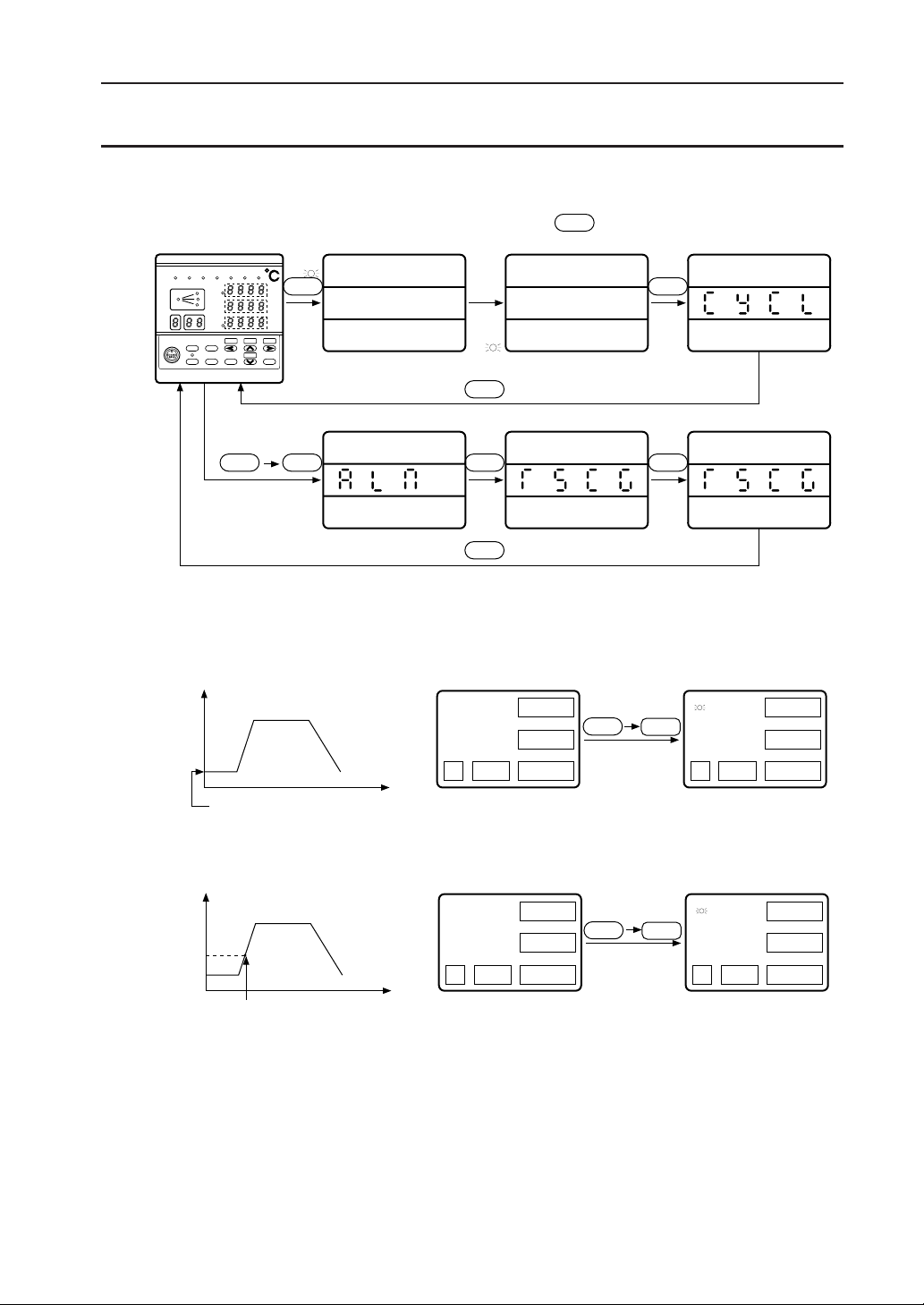
SECTION 2 PROGRAMMING
Channel menu screen
Programmers are requested to read this section carefully.
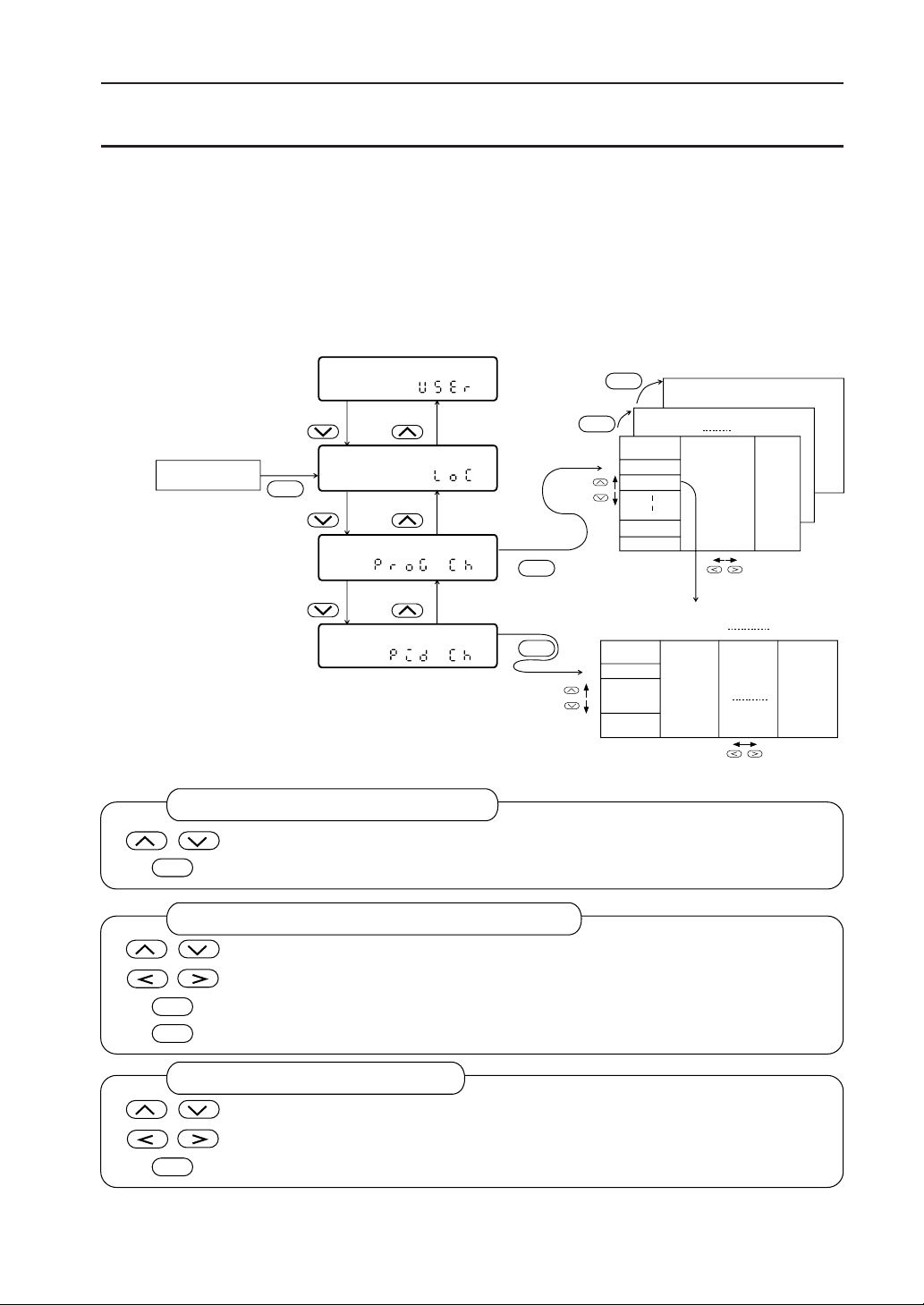
1. Parameter Structure and Parameter Calling Method
With this unit, nine 20-segment program patterns can be registered. Control parameters, such as PID
to be used in each segment, can be specified out of nine PID groups as illustrated below.
A program pattern is set with the program pattern setting channel, while a PID group is set with the
PID setting channel.
Operation profile
User level
Setting lock
DSP
Program pattern
PID set channel
()
()
Setting channel
()
()
Key operation on the channel menu screen
: Moves up and down in the channel menu.
SEL
: Selects a channel on display.
User
level
SEL
SEL
PTN
PTN
Segment 1 Segment 20
SV
TM
PID No.
No. 1 No. 2 No. 9
P
I
D
MAN
Pattern 9
Pattern 2
Pattern 1
Key operation on the program pattern setting channel
: Various parameters are moved up and down within one segment.
: A segment is moved up and down within one pattern.
PTN
SEL
: Patterns (1 to 9) are moved.
: Returns to the channel menu.
Key operation on PID setting channel
: Various parameters are moved up and down within one PID group.
: PID groups (1 to 9) are moved right and left.
SEL
: Returns to the channel menu.
2-1
Page 12
2. Program Pattern Setting (Program Pattern Setting Channel)
2.1 Program pattern structure
SV °C
100
50
0
[Programming map]
Segment
Pattern
PID No.
Alarm 1 set value
Alarm 4 set value
Time signal 1 ON time
Time signal 1 OFF time
Time signal 6 ON time
Time signal 6 OFF time
Guarantee soak Yes/No
Set value
Time
Display Setting range
Set value
Time
0 to 10000
0:00 to 99:59
1 to 9
0 to 10000
0:00 to 99:59
0:00 to 99:59
ALM1
T10N
T10F
Notation
Engineering
unit
hr:min or
min:sec
Number
Alarm
display
hr:min or
min:sec
hr:min or
min:sec
YES/NO
ON time
OFF time
12 3
Time
(hr:min)
Guarantee soak type
PV start
Number of cyclic
operations
Link pattern No.
0:Up and down
1:Down
2:Up
0 to 99
1 to 9
YES/NO
OFF or
1 to 99
OFF or
1 to 9
2-2
Page 13

The programming for this unit can be accomplished by setting parameters necessary for each of
In the case of ramp segment
In the case of soak segment
Segment n
Time setting for segment n Time setting for segment n
Set value for
segment n
Set value for
segment n
Set value for
segment n–1
Set value for
segment n–1
segments.
For each segment setting, the pattern setting (Setting of set value and time) and other supplementary
functional setting (such as PID number, alarms, and time signal) are required.
Program setting
Pattern setting
(Set value and time
setting)
Supplementary function setting
(PID No., alarm, time signal, and
so on)
1) Pattern setting
• The pattern setting includes the setting of a set value and time for each segment.
• Segment “n” would be a segment to which the process will flow from the set value for
segment “n-1” to the set value for segment “n” at the time set for segment “n.”
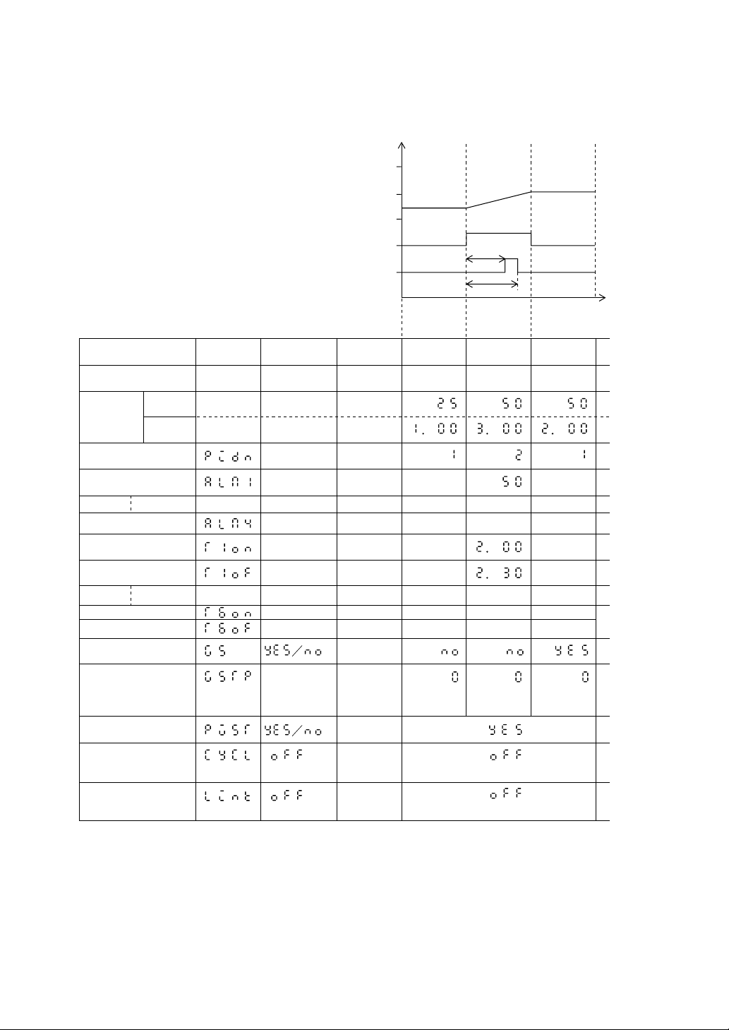
Example 1) In the event of segment 2 (n=2) on the programming map (Pages 2 to 3):
A pattern in which the process will flow from 25°C (set value for segment 1) to
50°C (set value for segment 2) in 3:00 hours(time setting for segment 2). This is
called “ramp segment.”
Example 2) In the event of segment 3 (n=3) on the programming map (Pages 2 to 3):
A pattern in which the process will flow from 50 °C (set value for segment 2) to 50
°C (set value for segment 3) in 2:00 hours(time setting for segment 3).This is
called “soak segment.”
• The first segment will always be a soak segment, because of no set value for segment “n-1.”
Example 3) For segment 1 on the programming map (pages 2 to 3), the process will be soaked
for 1:00 hour (time setting for segment 1) at a temperature of 25 °C (set value for
segment 1).
2) Setting for other supplementary functions
The setting of some supplementary functions is made for each segment, while the setting of others
is made only for one in a pattern.
Parameters to be set for each segment
• Setting of PID group number
• Setting of alarms 1 to 2 (or 1 to 4)
• Setting of time signals 1 to 4 (or 1 to 6)
• Setting of guarantee soak
Parameter to be set only for one in a pattern
• PV start specification
• Cycle setting
• Setting of pattern link
For particulars of each setting, see an appropriate section for each parameter.
2-3
Page 14
2.2 Pattern Setting...........[Setting of a set value (SV) and time]
Applicable
Operation
Segments 1 through 3 are registered according to the examples of program patterns.
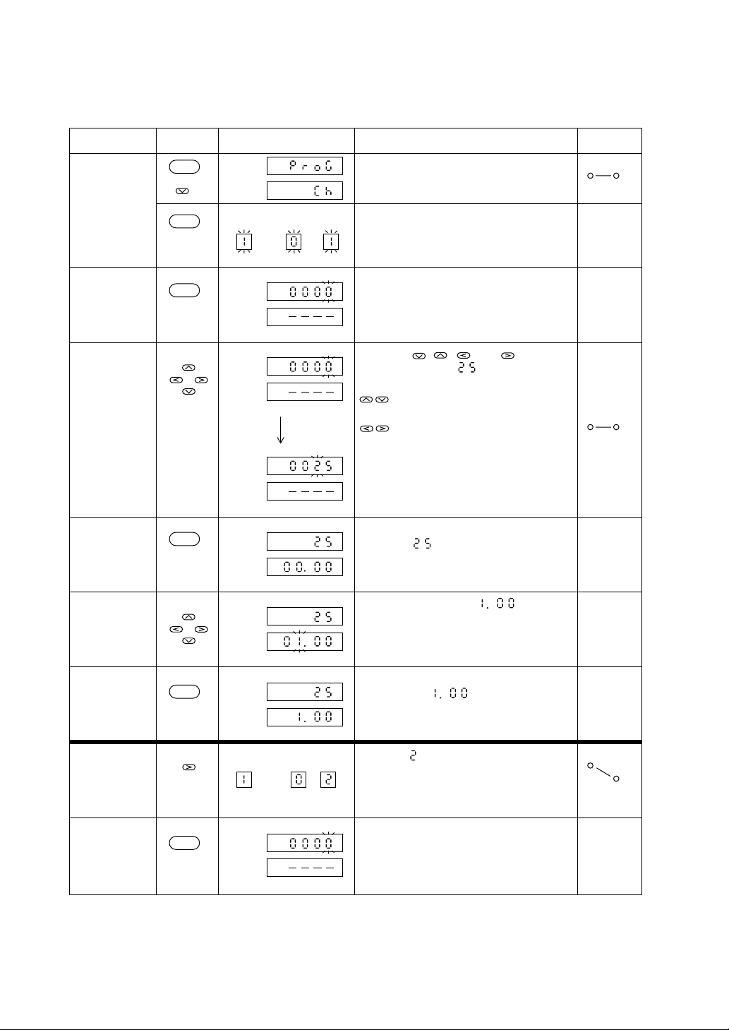
Step Display Explanation
Invoking a
parameter
key(s)
SEL
Program setting channel menu is invoked.
See “1. Parameter structure and Parameter
calling method.”
Enters the program setting channel.
Pattern and segment displays will blink.
Enters the set value mode and the set value
will blink.
By using , , , and keys, the
data is changed to .
: For decrement and increment of
Entering the
setting mode
(set value)
Changing data
(set value)
SEL
ENT
Pattern
Set
value
Time
Set
value
Time
Segment
data
: For selecting columns
Set
value
Time
Entering the
data entry set
mode (time)
ENT
Set
value
Time
The set value blinking will terminate and
the data “ ” is entered.
Concurrently, the time setting will blink,
entering into the time setting mode.
profile
Changing data
(time)
Entering data
(time)
Invoking
parameter
(segment
change)
Entering the
set value mode
ENT
ENT
Set
value
Time
Set
value
Time
Pattern Segment
Set
value
Time
The data is changed to .
The time setting blinking will terminate
and the data “ ” is entered.
Segment is invoked.
2-4
Page 15
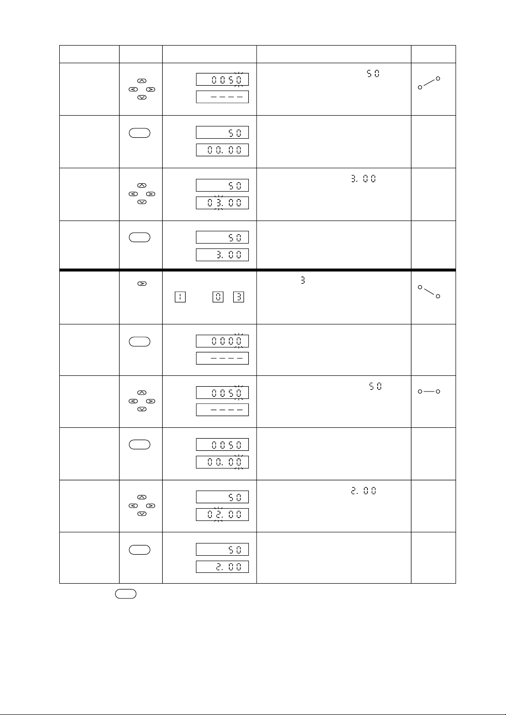
Step Display Explanation
Changing data
Applicable
key(s)
Set
The set value is changed to “ ”
value
Time
Operation
profile
Entering the
data entry
time setting
mode
Changing data
(time)
Entering data
(time)
Invoking
Parameter
Entering the
set value
mode
Changing data
ENT
ENT
ENT
Set
value
Time
Set
value
Time
Set
value
Time
Pattern Segment
Set
value
Time
Set
value
Time
The time is changed to “ .”
Segment is invoked.
The set value is changed to “ ”
Entering the
data entry
time setting
mode
Changing data
ENT
Set
value
Time
Set
The time is changed to “ .”
value
Time
Entering data
ENT
Set
value
Time
Note: Depress key for returning to the operating screen.
DSP
2-5
Page 16
2.3 Setting of supplementary functions
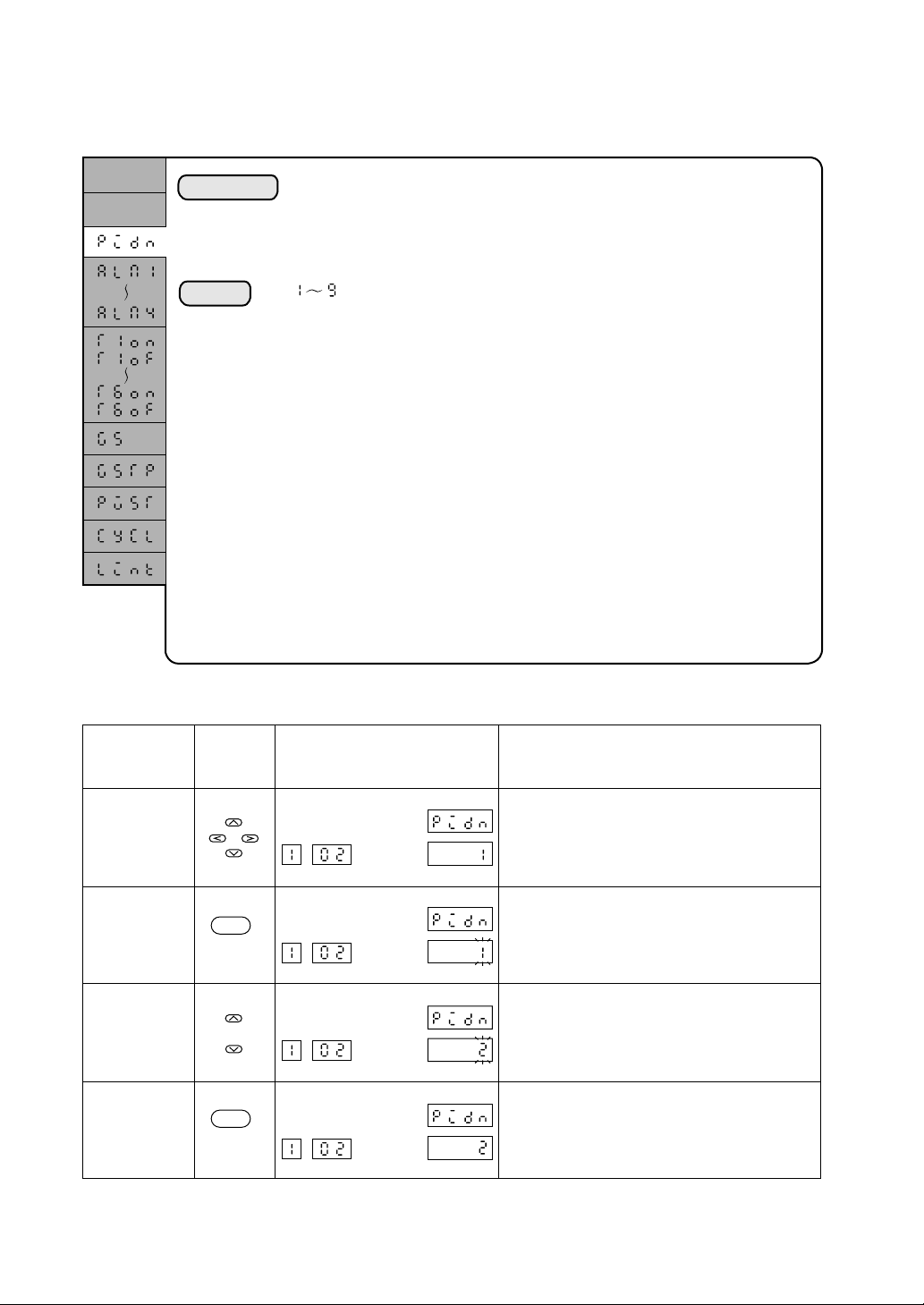
2.3.1 Setting of PID group
Set value
Time
Explanation
Setting
The PID group number (l to 9) is set for the use in that segment. In this
manual, the grouping of P, I, and D parameters and output limiters to be used
for the control operation is called “PID group.” The setting of PID group
contents is made through the PID setting channel.
: The PID group number is set.
A PID group number 2 is assigned to segment 2.
Step Display Explanation
Invoking
parameter
Applicable
key(s)
Pattern Segment
Set
value
PIDN in segment 2 is invoked.
Time
Entering the
setting mode
ENT
Pattern Segment
Set
value
The data will blink.
Time
Changing data
Pattern Segment
Set
value
The set value is changed to “2.”
Time
Entry
ENT
Pattern Segment
Set
value
The data blinking will terminate and the
data is entered.
Time
2-6
Page 17
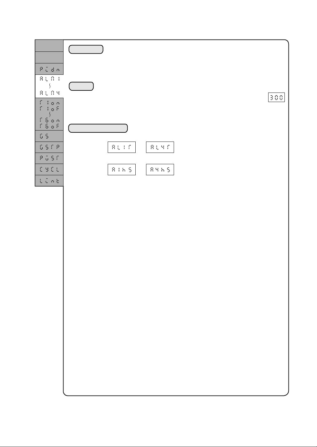
2.3.2 Setting of alarm values 1 to 4
Set value
Time
Explanation
A set value is established for the alarm to be generated in that segment. The
alarms are provided at two points (ALMl and ALM2) as a standard and,
optionally, it may be expanded to a total of four points (with additional points
ALM3 and ALM4).
For setting, engineering units are used. The setting range is 0 to 100% of the
input range.
Setting
0 to 100% (To be displayed in engineering units.)
Example) Where the input range of an instrument is 0 to 400°C, a value
Associated parameters
*: A change of the setting is not required for the ordinary use.
is used for the setting, if the alrm is to be generated at 300°C.
~
: Alarm type
(See System Setup Parameters)
*
~
: Alarm hysteresis
(Expert parameter)
2-7
Page 18
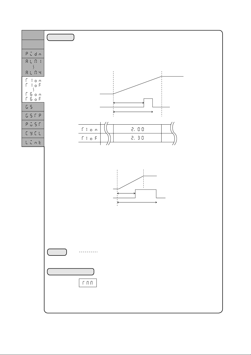
2.3.3 Setting of time signal
Set value
Time
Explanation
A time setting is made for the time signal.
The time signal will function to turn on/off the digital output (open collector)
according to the program running. For this unit, 4-point or 6-point time signal
may be provided.
The time signal setting can be established by setting an ON time and OFF time
starting from the beginning of a segment to be set.
ON time
Time signal 1
OFF time
• The time may be set even beyond the segment. Where, however, a time is set
again in the later segment, the preceding time setting will be nullified and the
present time setting will be validated because one timer is provided for each
time signal.
• In one segment only one ON and one OFF setting are allowed for each time
signal.
• In the reset state the time signal outputs will be all OFF.
• The time signal timer will be stopped in the holding state.
• The time signal output immediately before the end of operation will be
retained when the unit operation is ended.
Setting
0.00 to 99.59
Associated parameters
ON time
OFF time
: No setting
: 0 hr:0 min to 99 hr:59 min (or 0 min:0 sec to 99 min:59 sec)
: Time unit setting (switching between hr:min and min:sec)
(System setup parameter)
2-8
Page 19
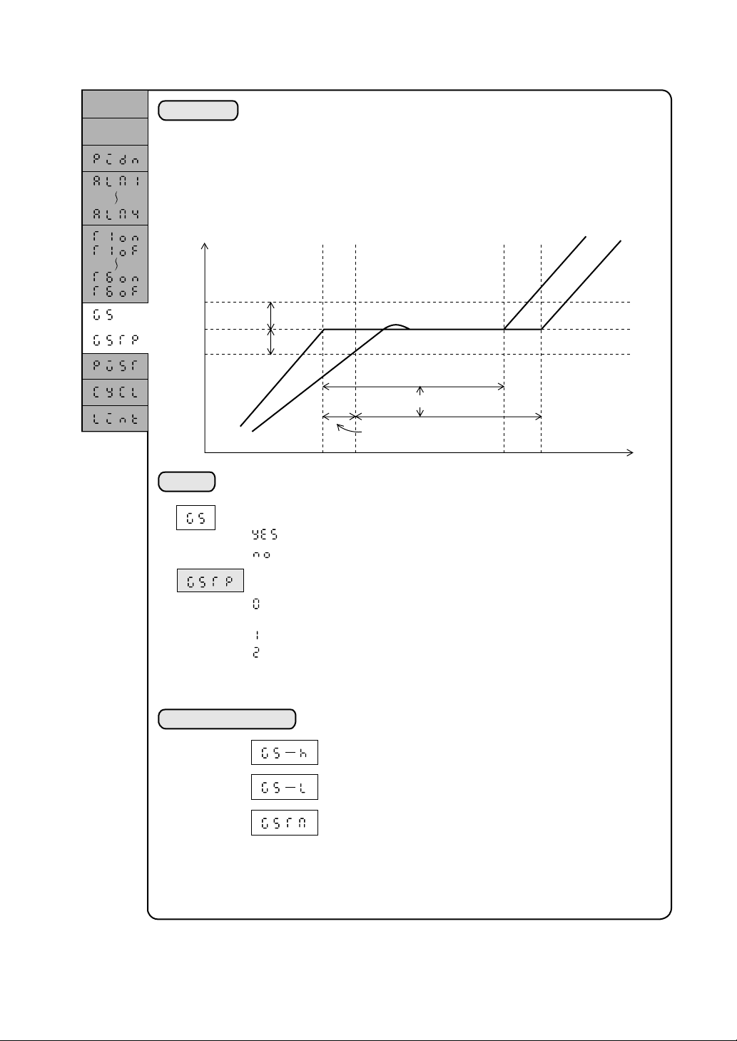
2.3.4 Guarantee soak............... (Waiting for PV to follow)
Set value
Time
Explanation
PV
Guarantee
soak
Guarantee
soak
Setting
• This is a function to suspend the timer operation at the beginning of a
segment for waiting, where the Process variable fails to follow the
running program in the program control.
When the Process variable enters a specified zone, the timer operation
will start again.
• The waiting is performed only once at the beginning of the segment.
Therefore, the timer operation will not be suspended again after the
Process variable once enters the guarantee soak zone and leaves out of
the zone after starting the progress of time.
Upper limit
setting
Lower limit
setting
Pattern that was set
Pattern actually executed
SV
PV
Set time for the segment
Timer operation will
suspend during this period.
Guarantee soak provided or not provided
* Guarantee soak type (Expert parameter)
* Note that this is an expert parameter and is displayed only
when Expert (2) is selected in the user level setting (USER).
Associated parameters
: Guarantee soak provided
: Guarantee soak not provided
: Wait until the PV enters the upper and lower zones.
(Standard)
: Wait until the measured value enters the lower zone.
: Wait until the measured value enters the upper zone.
: Guarantee soak upper limit setting (system setup parameter)
: Guarantee soak lower limit setting (system setup parameter)
: Guarantee soak max. wait time (system setup parameter)
2-9
Page 20
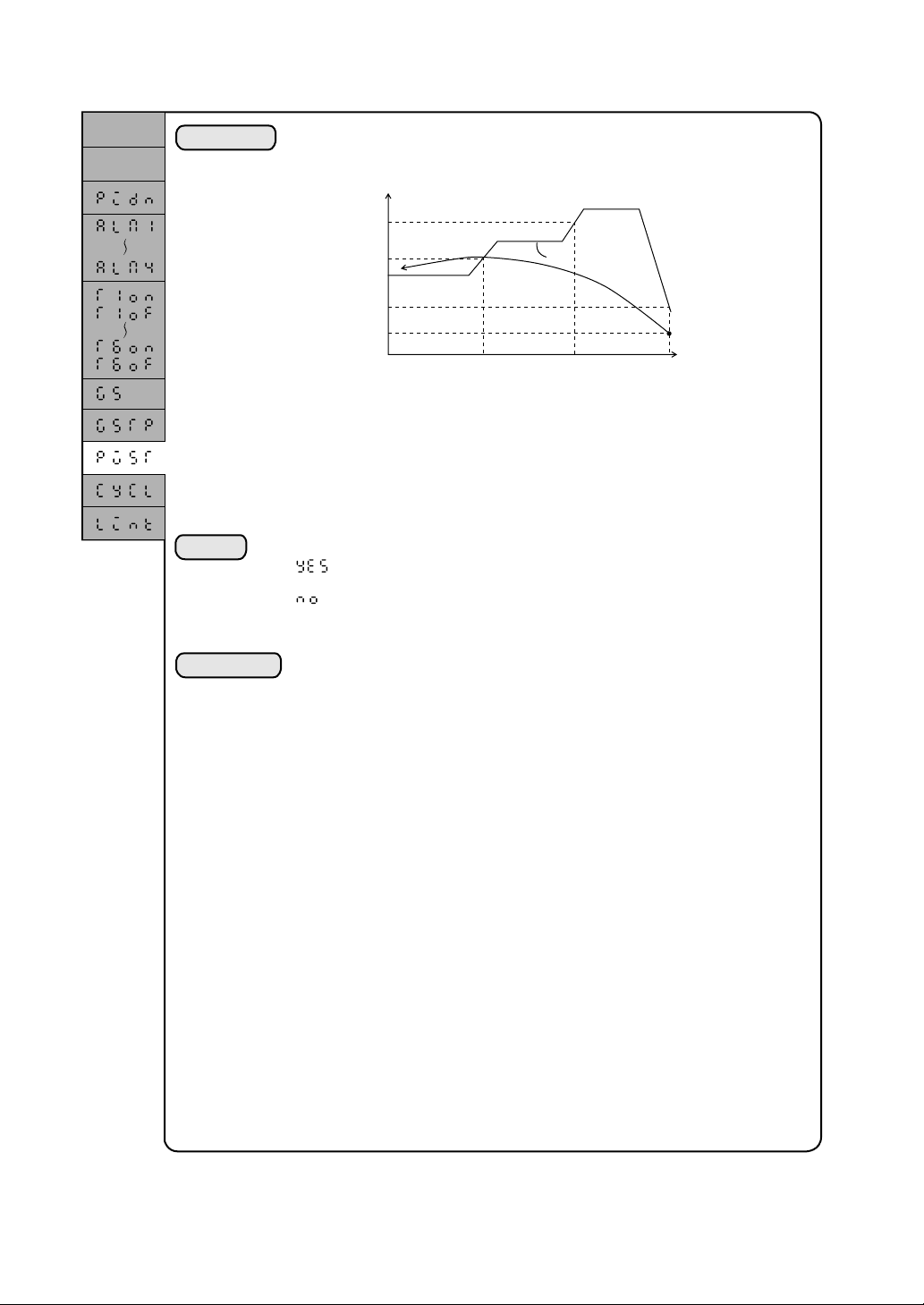
2.3.5 PV Start........... (Allowing the program to start from the current PV)
Set value
Time
Explanation
Setting
This function includes the seeking of a first point at which the PV
matches the program pattern after the start of a program and the starting
of the unit operation from that point.
Set value
①
②
Start
③
④
Start of ④
Note: Where there is no match point as in case ④, the operation will start
from the first segment.
• There is no difference between the PV start and the ordinary start in
the time-dependent relation between the program pattern and other
supplementary functions, such as time signal.
: PV start available
: PV start unavailable
Start of ② Start of ① Start of ③
SV
Time
Supplement
Only one parameter assignment is allowed for a single pattern. (The
setting is possible for any segment)
2-10
Page 21

2.3.6 Cyclic Operation........... (Repetitious execution of a pattern)
Set value
Time
Explanation
Setting
This is a function for the repetitious execution of the same program pattern.
Where the number of cyclic operations is assigned, the re-start will begin
with the first segment after the completion of the final segment.
• For the number of cyclic operations, the number of times of repetititious
operations is assigned for the setting. Therefore, the number of times of the
actual execution would be the number of cyclic operations plus one.
Number of times of execution = Set value for cyclic operation + 1[time]
Example) Where a program pattern is executed three times:
“2” is assigned to “ ”
Set value
One time Two times Three times
Time
: Cyclic operation is not performed.
: The number of times of repetition (Cyclic operations are
performed)
(The program pattern will be executed “set value + l” times)
Supplement
Only one parameter assignment is allowed for a single pattern.
(The setting is possible for any segment.)
2-11
Page 22

2.3.7 Pattern-Link Operation..........(Successive pattern execution)
Set value
Time
Explanation
Setting
This is a function for the consecutive execution of one pattern after the other
pattern is completed. For a program pattern with a link pattern number
assigned, the first segment with the assigned pattern number will be executed
after the final segment is completed.
Example) Where pattern 3 is executed consecutively after pattern 1:
“ ” is assigned to “ ” in pattern 1.
Set value
Pattern 1 Pattern 3
Time
: Pattern link operation is not performed.
: After one pattern is completed, a pattern with assigned number
is executed consecutively.
Relationship between link pattern and cyclic operation
The cyclic operation and the pattern link operation can be assigned in combination. In this case, the
cyclic operation is preferentially executed; after completion of the cyclic operation, the link pattern
will be executed.
Pattern 2 Pattern 5
Cycle 3
Link 5
4 times 3 times
Cycle 2
2-12
Page 23
2.4 Editing Program Pattern
Key
1234 12345
Time
Time
Key
1234 12345
TimeTime
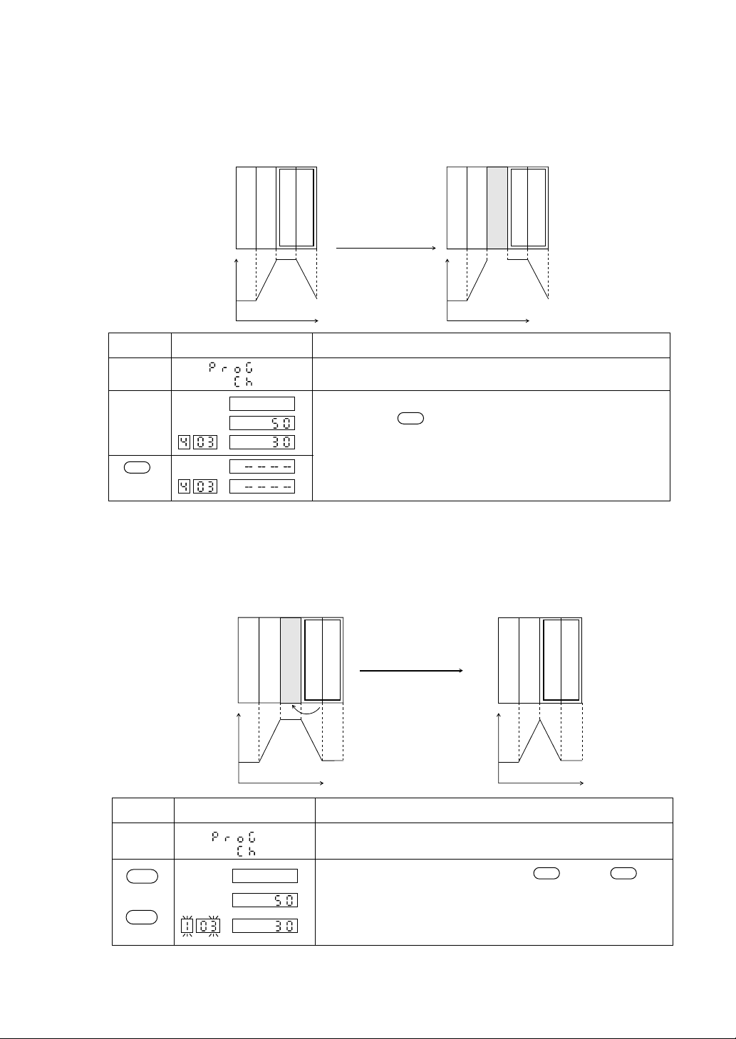
2.4.1 Segment insertion (a new segment is created between segments)
A new segment is inserted between segments.
To be inserted between
segment 2 and segment 3
Set valueSet value
operation
Display Explanation
This display is generated by referring to section 1.3
Parameter Setting Overview.
A pattern and a segment are selected.
By depressing key, the segment is inserted.
INS
As a result, the previous segment is shifted backward by one
segment.
INS
2.4.2 Segment erasure (a segment in a pattern is erased)
A segment is erased from a program pattern.
Segment 3 is erased
Set valueSet value
operation
SFT
CLR
DSP
Display Explanation
This display is generated by referring to Section 1.3 Parameter
Setting Overview.
A segment to be erased is selected. The key and key
SFT DSP
are depressed. The segment is erased and the succeeding
segment is shifted forward for the setting.
2-13
Page 24

2.4.3 Copying a pattern
A created program pattern is copied to another pattern.
Example) Pattern 1 is copied to Pattern 4.
Pattern 9
Pattern 1
Display ExplanationKey operation
COPY
SFT
ENT
Copy
Pattern 4
This display is generated by referring to Section 1.3
Parameter Setting Overview.
The program pattern sender assignment status is established
by depressing key and key.
SFT
ENT
A sender is assigned by using and keys.
ENT
By depressing key, receiver assignment status is
established.
ENT
A receiver is assigned by using and keys.
ENT
Copying operation will start by depressing key.
After completing the copying operation, a display “Copy
ENT
done” will be generated for a second.
Cautions in the copying operation
• Prior to the generation of the sender pattern, the program must be registered for entry.
The selection of an unassigned pattern at the sender will result in a sender error.
(Sender error)
• The receiver pattern must be erased. The selection of an assigned pattern at the sender will result in a
receiver error.
(Receiver error)
2-14
Page 25

2.4.4 Pattern erasure
Part of a program pattern is erased.
Key operation
COPY
SFT
ENT
ENT
ENT
Display Explanation
2.4.5 Erasure of all patterns
All the program patterns are erased.
Key operation
COPY
SFT ENT
Display Explanation
This display is generated by referring to Section 1.3
Parameter Setting Overview.
By depressing key and key, the program
SFT
ENT
pattern sender assignment status is generated.
A display “CLR” is generated by depressing key.
The destination assignment status is generated by
depressing key. Using key and key, a
ENT
program pattern to be erased is specified.
The erasing operation is performed by depressing key.
ENT
After completing the erasing, a display “Copy done” will
appear for a second.
This display is generated by referring to section 1.3
Parameter Setting Overview.
By depressing key and key, the program
SFT
ENT
pattern sender assignment status is generated.
A display “CLR” is generated by depressing key.
ENT
ENT
The destination assignment status is generated by
depressing key. A display “ALL” is generated by
ENT
depressing key.
All patterns are erased by depressing key.
ENT
After erasing, a display “Copy done” will appear for a
second.
2-15
Page 26

2.4.6 Change of running program
The set value is suddenly changed at this point.
The set value is changed
This unit operates only when a set pattern has been copied to a running pattern (Pattern 0) in
the pattern start timing. That is, the operation is always performed in pattern 0. For this
reason, any change in patterns 1 through 9 during the operation will have no impact on the
running operation. Change pattern 0, if any change is required for running program. (In this
case, the operation will have no impact by the change of a segment already executed)
Pattern 9
Pattern 1
Copying after
start of
operation
Pattern 0
Operating pattern
Caution: A set value will be suddenly changed according to a new setting when a set value
and time are changed in the segment under the execution. (In the case of the ramp
segment)
The change of a set value or time for the segment under execution should be
avoided, if an abrupt change in the set value is undesirable.
at this point.
Old pattern
New pattern
2-16
Page 27

3. Setting of PID Group (PID Setting Channel)
Group number1Group number2Group number
3.1 Structure of PID Setting Channel
A group of control parameters such as P,I, and D is assigned.
For this unit, a lump sum of control paramters such as P, I, and D manipulating value limits
(MV limits) is called “PID group.” Nine types of PID groups are available for setting.
When running a program, select and use one out of the nine types of control parameters for
each segment. (See PID number parameters)
Processing
status
SEL
Key lock
DSP
Program pattern channel
(
PID channel
)
(
)
(
)
SEL
Proportional
zone
Integral time
Differential time
Blind zone
MV upper limit
MV lower limit
Reverse
specification
Non-linear gain
Integral break
point
Manual reset
9
Code Name Setting range Remarks
P
I
d
GAP
MV-H
MV-L
Proportional zone
Integral time
Differential time
Dead zone
Manipulating
value (MV)
Upper limit
Manipulating
value (MV)
0.0 to 999.9
0 to 3200
0.0 to 900.0
0 to 50% of input
range
–5.0 to 105.0
–5.0 to 105.0
Notation
%
Second
Second
Engineering
unit
%
%
Lower limit
REV
KnL
Ar
MAN
Reverse operation
assignment
Non-linear gain
Integral break point
Manual reset
: Reverse operation
: Normal operation
–327.7 to 327.7%
0 to 100% of input
range
–5.0 to 105.0
YES/NO
%
Engineering
unit
%
Expert parameter
2-17
Page 28

3.2 Setting of each parameter
For PID group number 1, the following setting is made:
P=10.0%, I=50 seconds, and D=30.0 seconds.
Step
Invoking
parameter (P)
Entering data
setting mode
Changing data
Entry
Applicable
key
SEL
ENT
ENT
Display Explanation
Pattern Segment
PID ch is invoked by referring to “1. Parameter
Structure and Calling Method.”
By depressing key, the proportional zone
SEL
display will appear and concurrently the segment
display will blink. A number in the segment
represents a pertinent PID group number.
Use and keys to assign the PID group
number. In this case, the PID group number "1" is
assigned and no operation is required.
Depress key. The time display will start
ENT
blinking.
Use , , and keys to change the
numerical value for the proportional zone. In this
case, 10% is used.
Depress key. The PID group number will
ENT
blink again.
Invoking
parameter (I)
Entering data
setting mode
( )
ENT
By depressing key, the integral time (I) display
will appear.
(Use and keys to change any other group
number.)
Depress key to bring a state in which the
ENT
integral time can be input. Then the time display
will start blinking.
2-18
Page 29

Step
Changing data
Applicable
key
Display Explanation
Use , , , and keys to change the
numerical value for the integral time.In this case,
50(seconds) is set.
Entry
Invoking
data (I)
Entering data
setting mode
Changing data
Entry
ENT
( )
ENT
ENT
Depress key. The PID group number will
ENT
blink again.
By depressing key, the differential time (D)
display will appear.
(Use and keys to change any other group
number.)
Depress key to bring a state in which the
ENT
differential time can be input. The time display
will then blink.
Use , , , and keys to change the
numerical value for the differential time. A value
of 30.0(seconds) is used in this case.
Depress key, so that the segment display will
ENT
blink.
2-19
Page 30

3.2.1 Setting of proportional zone (P), integration time (I), and differentiation time (D)
Explanation
The proportional zone (P), Integral time (I), and differential time (D) are
assigned for the PID control.
Setting
1) Proportional zone (P)
0.0% : Two position control is performed.
0.1 to 999.9% : PID control is performed.
2) Integral time (I)
0 [sec] : The integral operation is eliminated.
1 to 3200[sec] : An integral time is assigned.
3) Differential time (D)
0.0[sec] : The differential time is eliminated.
0.1 to 900.0[sec] : A differential time is assigned.
Associated parameters
The blind zone setting is required when the two position operation is
performed with P=0.
3.2.2 Setting of blind zone
Explanation
The blind-zone functional operation will vary with the value of P.
1) P = 0 ········ In the two position operation
This function is to improve the control stability through the prevention of
the output fluctuation in the neighborhood by shifting the operating point
at the time when the Process variable rises and falls.
GAP GAP
Output ON
Setting
Output OFF
SV
PV
2) P ≠ 0 In the PID control
This function is to reduce wasteful manipulation to a minimum by
suspending the control, with the deviation (DV) set to "0" in the
neighborhood of the set value.
This function is used, where the PV may be in the neighborhood of the
set value (a reasonable amount of offset is allowed), as in the liquid level
control in a tank.
Deviation after the blind zone
(GAP) calculation
GAP GAP
Deviation
SV
No control is exercised during this period,
with no manipulating value (MV) changed.
0 to 100% of input range :
Display in engineering unit
2-20
Page 31

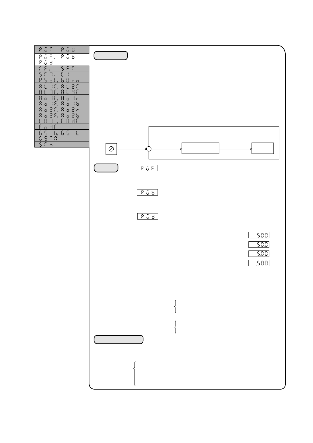
3.2.3 Manipulating value (MV) upper and lower limits
Explanation
Setting
Caution
The upper limit and the lower limit of manipulating value (MV) are
determined by set values, where the limitation of manipulating value (in
upward or downward movement) is required for processing reason or for the
convenience of an operating terminal.
When manipulating value (MV) is limited, the I operation in the direction that
the MV is leaving from the limit value will be cut, therefore, preventing an
over-integration by the limitation.
Limited MV
MV-H
MV-L
0% 100%
MV-L MV-H
Prior to MV
limitation
Upper limit of manipulating value (MV)
–5.0 to 105.0%
Lower limit of manipulating value (MV)
–5.0 to 105.0%
Set the MV-H and MV-L so that the MV-H is greater than MV-L.
3.2.4 Reversing specification
Explanation
Setting
This parameter is to change over the control; from the normal operation to the
reverse operation, or vice versa.
Normal operation : to be used for a process in which the PV falls with an
Reverse operation: to be used for a process in which the PV rises with an
:For reverse operation
:For normal operation
increment of the MV.
increment of the MV.
2-21
Page 32

3.2.5 Non-linear gain
Expert parameter
Explanation
DV
GAP
GAP
Setting
–327.6 to 327.6%
Associated parameters
Blind zone
3.2.6 Integration break point
Explanation
DV
100%
This function performs the setting of blind zone
(GAP) and the control of a non-inear gain.
50%
By using this function, the non-linear gain can be
0%
controlled by making the gain larger or smaller in
the neighborhood of the set value (SV).
Expert parameter
PV
SV
Setting
If the integral operation is involved in the control
operation, an overshoot will occur due to an
overintegration at the initial stage.
The overshoot is therefore prevented by limiting the
range of the integral operation. This setting is made
for an upper and lower limits with respect to the SV.
AR
AR
The integration
is eliminated
The integration
is eliminated
0 to 100% (Engineering unit) of the input range
2-22
Page 33

3.2.7 Manual reset
Expert parameter
Explanation
Setting
The setting is made to assign "0" to the offset (steady-state deviation) when
using the unit only with P operation.
This set value is added to the MV for the output.
SV
PID operation
PV
MV
+
+
Manual reset
Manipulating value (MV)
–25.0 to 125.0%
2-23
Page 34

SECTION 3 SETTING UP...Start-up and specifica-
tion changes
Read this section carefully when incorporating this unit into a system and starting up the system.
It is assumed that the reader of this section is already familiar with the basic operating method of this
unit. If not, the reader should read SECTION 1 BEFORE STARTING OPERATION before proceeding to this section.
1. Structure of System Setup Channel
What is System Setup Channel?
The system setup channel is a channel through which basic parameters, such as the input specifications
of PV and type of alarm, are set for the use of this unit to be incorporated into the system.
The setting and confirmation of parameters for this channel are required at the time of the system startup or when the specifications are changed.
Operation
profile display
User level
()
Setting lock
SEL
()
Program pattern
setting channel
()
PID channel
()
System setup channel
()
The system setup channel display
will appear only when the user level
is set to ‘1’ (Set maker).
SEL
PV input type
PV unit
PV full scale
PV base scale
Position of decimal point
Time constant of filter
PV shift
Start mode
MV proportional period
Preset MV value
MV at burnout
Alarm 1 type
Alarm 2 types
Alarm 3 types
Alarm 4 types
AO 1 output type
AO 1 output range type
AO 1 full scale
AO 1 base scale
AO 2 output type
AO 2 output range type
AO 2 full scale
AO 2 base scale
Time unit
Time display type
END signal output time
Guarantee soak - Upper limit
Guarantee soak - Lower limit
Guarantee soak - Max. wait time
Station number
3-1
Page 35

Code Name Setting range Notation Remarks
PVT
PVU
PVF
PVB
PVD
TF
SFT
STM
C1
PSET
BURN
AL1T
AL2T
AL3T
AL4T
PV input type
PV unit
PV full scale
PV base scale
Position of
decimal point
Time constant of filter
PV shift
Start mode
MV proportional
period
Preset MV value
MV set value at burnout
Alarm 1 type
Alarm 2 type
Alarm 3 type
Alarm 4 type
See Input code table
0: °C
1: °F
0 to 1000
0 to 1000
0: No decimal position
1: the first decimal position
2: the second decimal position
3: the third decimal position
0.0 to 900.0
–50.0 to 50.0% of the
input range
0: Continuous start
1: Reset start
1 to 120
–5 to 105.0
–5 to 105.0
See Alarm Type Table.
See Alarm Type Table.
See Alarm Type Table.
See Alarm Type Table.
–
–
–
–
–
Second
Engineering
unit
–
Second
%
%
–
–
–
–
Either one is
displayed depending on
the PV input type.
To be displayed if relay
or SSR drive output.
To be displayed if expanded
alarms (3&4) are installed.
0: PV
AO1T
AO1R
AO1F
AO1B
AO 1 output type
AO 1 output range type
AO 1 full scale
AO 1 base scale
1: SV
2: MV
0: 1–5V
1: 0–5V
2: 0–10V
0 to 100.0% of
the input range
0 to 100.0% of
the input range
–
–
Engineering
unit
Engineering
unit
To be displayed if auxiliary
analog signal output is
provided.
0: PV
AO2T
AO2R
AO2F
AO2B
TMU
TMDT
ENDT
GS-H
GS-L
GSTM
AO 2 output type
AO 2 output range type
AO 2 full scale
AO 2 base scale
Time unit
Time display type
END signal output time
Guarantee soak:
upper limit
Guarantee soak:
lower limit
Guarantee soak:
max. wait time
1: SV
2: MV
0: 1 to 5V
1: 0 to 5V
2: 0 to 10V
0 to 100.0% of
the input range
0 to 100.0% of
the input range
0: hr:min
1: min:sec
0: remaining time
1: lapsed time
0 to 99.59
0 to 50.0
0 to 50.0
00 to 99.59
–
–
Engineering
unit
Engineering
unit
Remaining
time
Lapsed time
Engineering
unit
Engineering
unit
Hr:Min
(Min:Sec)
To be displayed if 2-point
auxiliary analog signal
output is provided.
Hr:min or min:sec
display depending on the setting
of time unit.
Hr:min or min:sec
display depending on the setting
of time unit.
To be displayed only when
STN
Station number
00 to 99
T-link transmission is
provided.
3-2
Page 36

2. Setting of Each Parameter
●
●
●
●
●
●
●
●
●
●
●
●
●
●
●
●
●
●
●
●
●
●
●
●
●
●
●
●
●
●
●
●
●
●
●
●
●
●
●
2.1 Setting of PV input type and input range
Explanation
The PV input type and the input range are selected from the table
below so that the setting can be made in codes.
Table 1. Input signal and manipulation range
Input signal Input type
Resistance
bulb,
JIS(IEC)
Resistance
bulb
(Former
JIS)
Thermocouple
DC
voltage
Direct
Pt100
Pt100
Pt100
Pt100
Pt100
Pt100
Pt100
Pt100
JPt100
JPt100
JPt100
JPt100
JPt100
JPt100
JPt100
J
J
K
K
K
R
B
T
T
E
E
S
N
U
WRe5-26
PL-II
DC1 to 5V
DC0 to 5V
DC0 to 10V
DC0 to 1V
DC0 to 100mV
DC0 to 10mV
DC4 to 20mV
00
01
02
03
04
05
06
07
10
11
12
13
14
15
16
20
21
22
23
24
25
26
27
28
29
2A
2B
2C
2D
2E
2F
40
41
42
43
44
45
40*
current
Notes:
• The 0.1°C/°F notation is not provided for a temperature span greater than
Manipulation
range Code (°C)
0 to 150°C
0 to 300°C
0 to 500°C
0 to 600°C
–50 to 100°C
–100 to 200°C
–199.9 to 600°C
–199.9 to 850°C
0 to 150°C
0 to 300°C
0 to 500°C
0 to 600°C
–50 to 100°C
–100 to 200°C
–199.9 to 600°C
0 to 400°C
0 to 800°C
0 to 400°C
0 to 800°C
0 to 1200°C
0 to 1600°C
0 to 1800°C
–199.9 to 200°C
–150 to 400°C
0 to 800°C
–199.9 to 800°C
0 to 1600°C
0 to 1300°C
–199.9 to 400°C
0 to 2300°C
0 to 1300°C
From –999 to 9999
(Scaling range)
* The current must be input on
1 to 5 volts, with a 250-ohm
resistor (optional) connected
to terminal numbers 38 and
39.
Manipulation
range Code (°F)
32 to 302°F
32 to 527°F
32 to 932°F
32 to 1112°F
–58 to 212°F
–148 to 392°F
–328 to 1112°F
–328 to 1562°F
–148 to 392°F
–328 to 1112°F
–328 to 1472°F
32 to 302°F
32 to 527°F
32 to 932°F
32 to 1112°F
–58 to 212°F
32 to 752°F
32 to 1472°F
32 to 752°F
32 to 1472°F
32 to 2192°F
32 to 2912°F
32 to 3727°F
–328 to 392°F
–238 to 752°F
32 to 1472°F
32 to 2912°F
32 to 2372°F
–328 to 752°F
32 to 4172°F
32 to 3272°F
1000°C/°F.
• No guaranty is provided for the accuracy at a temperature below 200 .
• The LLLL display will not appear even with an input of zero ohm within a
range from -199.9 to 850 for the resistance bulb input.
• For the resistance bulb input , the LLLL or UUUU display will appear when
B-wire is broken.
0.1 °C
notation
×
×
×
×
×
×
×
0.1 °F
notation
×
×
×
×
×
×
×
×
×
×
×
×
×
×
×
×
3-3
Page 37

2.2 Setting of PV display unit (°C or°F) and 0.1°C (°F) notation
(for thermocouple or resistance bulb)
Explanation
Setting
Example of setting
The setting is made for temperature display; whether the PV is
expressed in the unit of 1°C (°F) or 0.1°C (0.1°F).
The changeover between and °F is accomplished by the PV
unit , while the changeover between 1°C and 0.1°C is
done by the decimal point position parameter.
PV unit
Position of decimal point 0: 1°C notation
Note: If the input span exceeds 1000°C /°F, the display in the
unit of 0.1°C /°F is not available.
1) The display in the unit of 0.1 is executed with an input
temperature, –150 to 100 to the resistance bulb (JIS).
PVT=4 (Pt100 in the range from –150 to 100 )
PVU=0 (°C notation)
PVd=1 (0.1°C notation)
2) The display in the unit of °F is executed with an input
temperature of 0 to 400°C to K thermocouple.
PVT=22 (K in the range from 0 to 400°C)
PVU=1 (°F notation)
PVd=0 (1°F notation)
0: °C notation
1: °F notation
1: 0.1°C notation
3-4
Page 38
2.3 Setting of full scale and base scale in the engineering unit notation (for DC voltage and current input)
Explanation
Pressure gauge
0 to 10kgf/cm
DC4 to 20mA 0 to 100% 0.0 to 10.0%
Setting
The DC voltage and the current are input within the range from 0
to 100% of the input range. The units of these values are converted
(scaling) into units being used for actual processing (engineering
units). Such units are called “engineering units.”
This unit permits the display of scaling an input measured value
between 0 and 100% within the range from –999 to 9999.
Example) A display of 0.0 to 10.0 is obtained from the input value
measured with a 0-10kgf/cm
receiving the value at 4 to 20 mA DC.
This unit
2
Scaling
PV full scale setting (–999 to 9999)
The setting is made for a desired value to be
displayed at 100% input.
PV base scale setting (–999 to 9999)
The setting is made for a desired value to be
displayed at 0% input.
Position of decimal point
The setting is made for a decimal place.
2
pressure gauge by
Display
4.3
Example of setting
0: No decimal point
1: the first decimal position
2: the second decimal position
3: the third decimal position
Note) The setting must be made so that the full scale setting is
greater than the base scale setting.
Good example)
Bad example)
With an input of 4 to 20 mA DC a display of 0.0 to 10.0 will
appear.
PVT = 40 ············· 4 to 20 mA DC input range code
PVF = 100 ··········· A display of 100 by 100%(20 mA) input.
PVF = 0 ··············· A display of 0 by 0% (4 mA) input.
PVd = 1 ··············· The first decimal position
PVF=500
PVb=–250
PVF=–250
PVb=500
3-5
Page 39

2.4 PV filter ....... (reducing the wander of PV arising from noise)
Explanation
Setting
The measurement fluctuation due to the input noise is reduced to a
minimum. Where the value of P (proportional zone) is small, a
small variation of PV will produce a large MV, thus bringing
about an effect of stabilizing the control with a filter. For this unit,
a first-order-lag filter is used and the setting is made with a firstorder-lag time constant.
without filter
PV
63.2%
time
time constant
The time constant is defined as a time required for the input
value to attain 63.2% of the original input value.
Large
↑
Time constant
↓
Small
0.0 : PV filter is not used.
0.1 to 900.0 sec.: PV filter is applied according to the assigned
·············
·············
·············
Setting of PV filter time constant
Slow
↑
Response
↓
Fast
time constant (second).
2.5 PV shift (shifting zero point of PV)
Explanation
Setting
This is a function to shift a PV by a set value.
PV
–50% to 50% of the input range (Notation in engineering units)
+
PV shift set value
PV shift setting
3-6
+
Display
SV
PID operation
Page 40

2.6 Start mode... (defining a startup mode at resumption of power supply)
Explanation
Setting
The start mode is defined when the power supply is resumed.
Two types of the start mode is available: continuous and reset.
Continuous: the operation at the time of power failure is resumed.
Reset : the reset state is established.
Start mode
0: continuous
1: reset
2.7 MV proportional period .... (for relay-drive or SSR/SSC-drive output)
Explanation
This is the setting for the MV proportional period in the relay
output or in the SSR/SSC-driven output.
In the relay output or the SSR/SSC-driven MV, the value of MV,
0 to 100%, is output by means of pulse width modulation
(PWM). The setting is made for this period. Although the
shorter period brings about better response, thus improving the
controllability, the frequency of ON/OFF operation will increase.
The setting, therefore, should be made in consideration of the
service life of the operating terminal.
(Since the SSR/SSC-driven output involves no problem of the
service life, the setting of 1 second is recommended.)
Output ON
Output OFF
Setting
Example) The operation in the case of MV=60%
60%
40%
Output proportional
period
Output proportional period
1 to 120 sec.
3-7
12 sec. 0.6 sec.
8 sec. 0.4 sec.
in the case of 20 sec. in the case of 1 sec.
Page 41

2.8 Setting of preset MV .... (defining MV in the reset state)
Explanation
Setting
The value of MV is defined in the reset mode.
In the reset mode a value assigned to this parameter is an output
as the MV.
Preset MV setting
–5.0 to 105.0%
2.9 Burnout MV setting ..... (defining MV at the burnout)
Explanation
The setting is made for an output value of MV at the time of the
input burnout or at a fault state such as the trouble with the unit.
Because this being an uncontrollable state, the value should be
set so that the processing may be developed into the safe side.
Setting
MV setting at the burnout
–5.0 to 105.0%
3-8
Page 42

2.10 Setting of alarm type
Explanation
Setting
The type of alarms, 1 to 4, (3 and 4 are optional) is assigned.
Setting of alarm types 1 to 4
Code Type
0
1
2
3
4
5
6
7
8
9
10
11 to 18
No alarm
Upper
threshold
Lower
threshold
Upper
deviation
Lower
deviation
Upper
deviation
(Turn-over)
Lower
deviation
Upper and
lower deviation
(Turn-over)
Upper and
lower deviation
(Turn-over)
Guarantee
soak timeout alarm
fault
with HOLD for 1 - 8 above
No alarm is used.
Alarm set value
Alarm set value
Alarm set value
SV
Alarm set value
SV
Alarm set value
Where the PV fails to enter the specified range before
the maximum wait time is lapsed
Where the unit becomes faulty, such as the input
burnout
SV
SV
Alarm set value
SV
SV
PV
PV
PV
PV
Alarm set value
PV
PV
PV
Alarm set value
PV
What is an alarm with "HOLD"?
The alarm with "HOLD" is a type of
alarm to be generated, where the PV
enters an alarming range without
causing the alarm ON, letting the PV
to leave the alarming range, but again
enters the alarming range.
This is an effective function for using
a deviation alarm in step-type
programming.
The alarm standby (supervision for alarm OFF and deviation from the range) is performed in the
following cases:
• when the alarm set value is changed
• when the alarm type is changed
• when the set value (SV) is changed (however, no standby is performed when the SV is changed in
the ramp segment.)
Upper & lower
PV
limit deviation
alarm
Pattern
Time
Upper & lower
limit deviation
alarm
Upper & lower
limit deviation
alarm with HOLD
3-9
Page 43

2.11 AO output type ..... (sending PV, SV, and MV to auxiliary analog
output)
Explanation
Setting
Caution
The setting is made for the type of a signal to be sent to auxiliary
analog signal outputs 1 and 2.
AO1T and AO2T AO output type
0: PV
1: SV
2: MV
If PV is selected in the AO output type, about 10.5 V is output in
the input burnout.
3-10
Page 44

2.12 AO range and scale ......(scaling auxiliary analog output)
Explanation
Setting
Caution
The outgoing analog signal for this unit, with 0 to 10 VDC output
capability, permits a change in the range and the scaling for the
connection with other receiving instruments.
AO output range
0: 1 to 5V
1: 0 to 5V
2: 0 to 10V
AO output full-scale
A desired output value, 100% of the AO output range, is assigned
in engineering units.
• When the output type is PV or SV:
0 to 100% of the input range (in the industrial value notation)
• When the output type is MV:
0 to 100% (in the percentage notation)
AO output base scale
A desired value for 0% output of the AO output range is assigned
in the engineering unit notation.
• When the output type is PV or SV:
0 to 100% of the input range (in engineering units)
• When the output type is MV:
0 to 100% (in percentages)
If the input range is 0 to 400 , a set value (SV) of 50 to 350 is
output to AO1 on 0 to 5 VDC.
AO1T=1 ·············· SV is output.
AO1r=1 ··············· An output range of 0 to 5 VDC
AO1F=350 ·········· 100% output at 350°C
AO1b=50 ············· 0% output at 50°C
2.13 Time unit ..........(switching from hr:min to min:sec or vice versa)
Explanation
Setting
A time unit is set for the time display or for time setting.
TMU time unit
0: hr:min
1: min:sec
3-11
Page 45

2.14 Setting of time display type ...... (switching from remaining time to
lapsed time or vice versa)
Explanation
Setting
Either "Remaining time indication" or "Lapsed time indication"
is set for the time display in the operating screen.
0: Remaining time indication
1: Lapsed time indication
2.15 END signal output time
Explanation
The setting is made for the time of turning on the END signal
(optional) in the profile output of this unit at the end of a program.
TMdT Type of time display
Setting
ENDT END signal output time
0.0 to 99.59 hr:min
(min:sec)
3-12
Page 46

2.16 Guarantee soak waiting allowance and setting of max. wait time
Explanation
• Garantee soak wait time allowance
This is the time setting for the resumption of time counting in
the guarantee soak.
Upper set value for guarantee soak
Lower set value for guarantee soak
Pattern
• Max. wait time in the guarantee soak
A function to resume the time counting automatically at the
lapse of a predetermined time even if the measured value has
not entered the guarantee soak wait time while waiting in the
guarantee soak.
Setting
0 to 50% of the input range (in engineering unit)
0.0 to 99.59 hr:min (min:sec)
Supplement
This unit is capable of generating an alarm when the time
counting is resumed automatically at the lapse of the max. wait
time while waiting in the guarantee soak. (See section 3.2 (10)
Alarm Type Setting)
The time countting is suspended for this period.
Guarantee soak upper & lower
threshold values
G5TM Max. wait time in guarantee soak
2.17 Setting of T-link station number
Explanation
Setting
T-link station number is assigned.
STN T-link station number
0 to 99
3-13
Page 47

3. Various Operating Methods
3.1 In this unit the operation mode (operating profile) can be changed over as illustrated below.
Not required for the ordinary use.
A/M FIX A/M
SFT SFL SFT SFL
SFT
PTN
Fixed-value
manual operation
Behaviors of SV and MV in various modes
• Program reset mode ········ Stand-by mode in the running of a program
SV ········· SV value in the 1st segment of the current pattern selected
MV ········ Preset MV
• Program (Run, hold, and end) ········ Program running mode
SV ········· According to the program pattern
MV ········ Automatic (calculated value by PID)
Fixed-value
automatic operation
Program (reset)
Holding Running
End
Manual program
operation
RUN
SFT
HLD
SFT
RST
SFT
• The changeover to the fixed-value automatic mode can be made only from the program reset mode.
• Manual program operation ··········· The mode switched from the program mode to the manual
operation. In this case, the program will run in its own course.
However, the program will keep on running by switching to the
manual operation while the program is running.
SV ········· according to the program pattern (running in its own course)
MV ········ MV set value from the keyboard
• Fixed-value automatic operation ········ Fixed-value running mode
SV ············SV set value from the keyboard. The value would be equal to PV when the program
mode is switched to the fixed value mode.
MV ········· Automatic (calculated value by PID)
• Fixed-value manual operation ········ Manual operation mode
SV ········· Before switching to the manual operation
MV ········ MV set value from the keyboard.
3-14
Page 48

Operation at the changeover of mode
MV ········ Balanceless, bumpless
SV ········· Program → Fixed value ········ PV tracking
Others ········ Continuous or running in its own course
3.2 Auto tuning
In the auto tuning the most common control constants are automatically set.
RUN HLD
PV
SV
TM
SFT
DV
AT
+
INS
SV
TM
• The auto tuning can be applied when the operating profile is in the fixed value mode, in
the program running mode, or in the program holding mode.
• If the auto tuning is applied in the program running mode, the time count will be suspended and the program will stop running.
• However, the program operation will be restarted when the auto tuning is terminated.
• The application of the auto tuning in the neighborhood of an operating SV is recommended under the normal circumstance.
3-15
Page 49

3.3 Fixed value operation
Program reset
The switching to the fixed value operation is possible only when the program operation is in
the reset state.
(The switching to the reset state from the fixed value state, or vice versa, can be accomplished by toggle action.)
PV
SV
SFT
FIX
PTN
Fixed-value
PV
SV
TM
ENT ENT
MV
PV
SV
MV
SV change
In the fixed value operating mode, “Fix Channel” ( ) will appear in the channel
menu.
SEL
PV
SV
MV
SEL
Setting lock
FIX channel
( )
Alarm 1 set value
Alarm 2 set value
Alarm 3 set value
Alarm 4 set value
( )
PID No.
Program pattern channel
( )
Proportional zone
Integration time
Differentiation time
PID channel
( )
Blind zone
MV upper limit
Setup channel
( )
MV lower limit
Reverse operation
Non-linear gain
Integration break
point
Manual reset
Parameters from (Proportional zone) to (Manual reset) can call the PID group set
number, 1 to 9, in this area by setting (PID group number) to any of the numbers 1
to 9 in the same structure as that of the PID channel parameter.
3-16
Page 50

3.4 Manual operation
Fixed-value automatic Manual
This is an operating mode in which the manipulating value (MV) setting is performed from
the front keyboard.
MANUAL ⇐⇒ AUTO switching can be accomplished by toggle action.
PV
SV
MV
SFT
A/M
SEL
MAN
PV
SV
MV
ENT ENT
MAN
PV
SV
MV change
MV
3.5 Remote operation (Option)....(for the entry of external commands and
selected pattern and the output of status)
This is an optional function available when this unit is used in combined use of some
external devices, such as a command switch, digital switch, and sequencer.
External command entry
Pattern selection entry
External command entry Pattern selection entry
PVX PVX
DI-RESET
DI-RUN
DI-HOLD
DI-ADVANCE
Reset
32
Run
33
Hold
34
Skip
35
DI-2
DI-2
DI-2
DI-
2
PVX
3
3
2
1
0
2
22
23
24
25
2
2
1
2
0
2
Status output
(Operation profile output)
Status output
PVX
Reset
Run/Hold
14
15
End
16
DO-RESEDT
DO-RUN
/HOLD
DO-END
DI-COM
36
DI-COM
26
3-17
17
DO-COM
Page 51
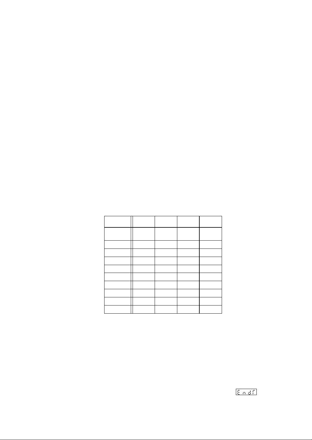
(1) External command entry
Selected
• A corresponding command is accepted when DI-RESET, DI-RUN, DI-HOLD, or
DI-ADVANCE is turned ON for more than 0.5 sec.
• Since a command is accepted at the startup, (OFF → ON), turn OFF for more than
0.5 sec. and then turn ON again if the successive entry of a command such as SKIP
is required.
• The concurrent entry of some different commands will be accepted in the following
preferential order:
RESET > RUN > HOLD > SKIP
• The same priority is given to the keyboard entered command and the external DI
input command. Therefore, a command accepted later will be validated.
(2) Pattern select entry
A pattern is selected with DI-23, DI-22, DI-21, or DI-20, as shown in the table below.
A pattern is selected by continuous DI input for more than 0.5 sec. for the input pattern
number.
For the external pattern input and the front pattern select key entry, the following
priority is given:
EXTERNAL PATTERN SELECTION > FRONT PATTERN SELECT KEY
The pattern may be selected with the front pattern select key only when the external
pattern select entry is ‘0’ (the state in which none of DIs are ON).
pattern
Pattern selected
from keyboard
1
2
3
4
5
6
7
8
9
Pattern Number = 9 is selected where the combination with DI-20 through DI-23 is other
than the above.
(3) Status output (Operating profile output)
This is a function to output an operating profile of this unit.Use this function as an
ACKNOWLEDGE signal when linking with the sequencer.
DO-RESET: Turns ON in the reset state.
DO-RUN/HOLD:
DO-END: Turns ON at the end of a program during the time set for signal
output time.
DI-23DI-22DI-2
OFF
OFF
OFF
OFF
OFF
OFF
OFF
OFF
ON
ON
ON: Running state
OFF: Holding state
OFF
OFF
OFF
OFF
ON
ON
ON
ON
OFF
OFF
1
OFF
OFF
ON
ON
OFF
OFF
ON
ON
OFF
OFF
DI-2
OFF
ON
OFF
ON
OFF
ON
OFF
ON
OFF
ON
0
3-18
Page 52

SECTION 4 ADVANCED USAGE
This section describes the PVX expert parameters. Those who want to make full use of this unit or to
explore a new type of the usage are requested to read this section.
1 Structure of expert parameter channel
Operation
profile display
User level
( )
Setting lock
SEL
( )
Program pattern channel
( )
PID channel
( )
System setup channel
( )
Expert parameter
( )
Set value upper limit
SEL
Set value lower limit
MV variation limit
Alarm 1 hysteresis
Alarm 2 hysteresis
Alarm 3 hysteresis
Alarm 4 hysteresis
DV differential mode
AT SV mode
AT PID mode
Transmission write inhibit
The expert parameter channel is displayed only when the user level is ‘2’ (Expert).
Code Name Setting range Notation Remarks
SV-H
SV-L
DMV
Set value upper limit
Set value lower limit
MV variation limit
0 to 100% of the input range
0 to 100% of the input range
0.0 to 105.0
Engineering
units
Engineering
units
%
A1HS
A2HS
A3HS
A4HS
DVDV
ATSV
PID
TDS
Alarm 1 hysteresis
width setting
Alarm 2 hysteresis
width setting
Alarm 3 hysteresis
width setting
Alarm 4 hysteresis
width setting
DV defferential
specification
AT SV mode
AT PID tuning
specification
Transmission write
inhibit
0 to 50% of the input range
0 to 50% of the input range
0 to 50% of the input range
0 to 50% of the input range
: DV differentiation
: PV differentiation
0: Standard
1: Low PV type
0: PI tuning
1: PID tuning
: Write inhibit
: Write enable
4-1
Engineering
units
Engineering
units
Engineering
units
Engineering
units
To be displayed only
when alarms 3 and 4
are provided.
Page 53
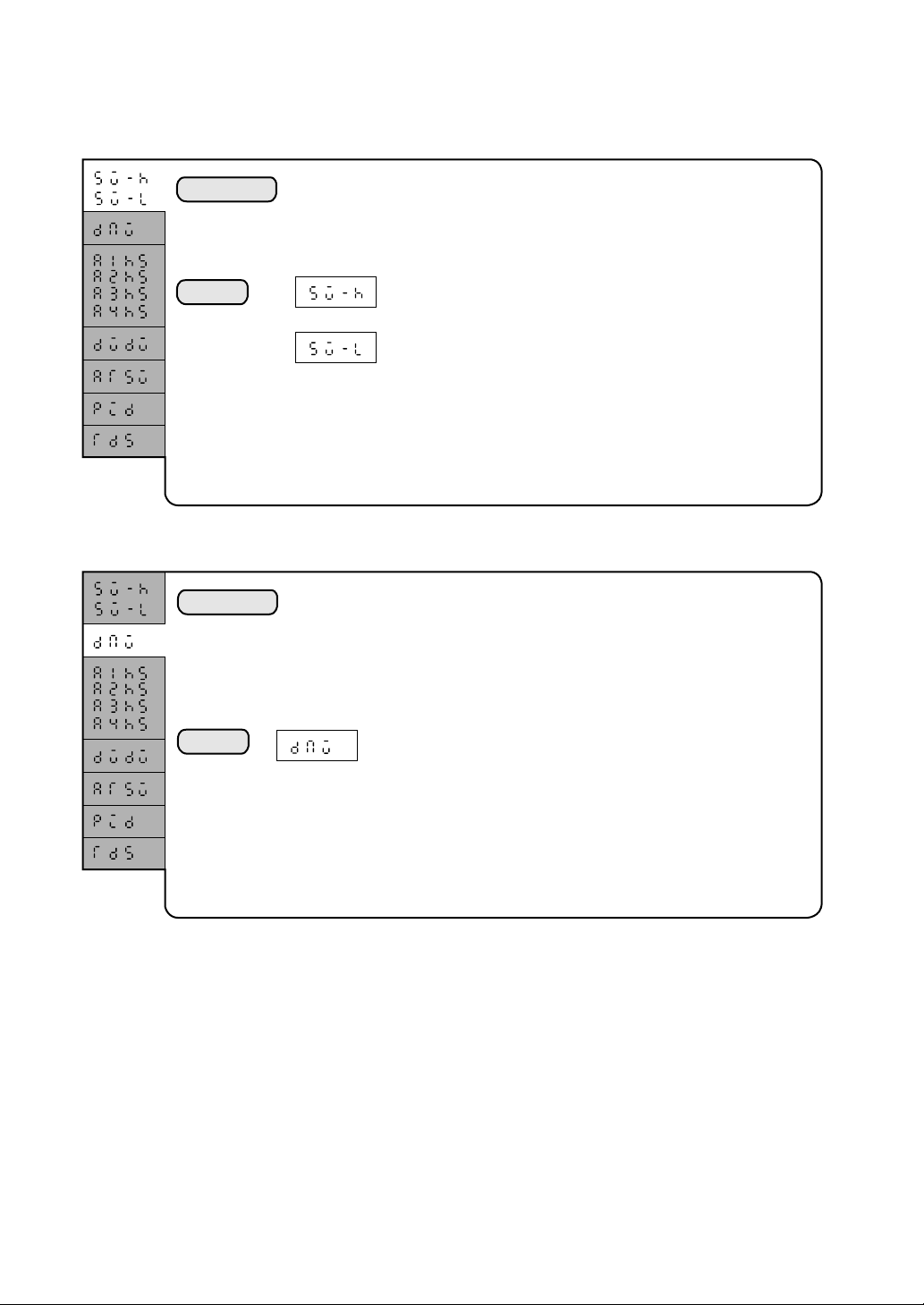
2 Setting of each parameter
2.1 Set value (SV) upper and lower limits
Explanation
Setting
The range of a set value (SV) is limited with an upper limit and a lower limit.
As a result, a value may be set within the limited range when the set value is
changed from the keyboard or through the transmission.
Set value (SV) upper limit
Set value (SV) lower limit
0 to 100% of the input range
(Engineering units)
2.2 Manipulating value (MV) variation limit
Explanation
The restriction is placed on a variation fo the MV in the automatic operation
(the state in which the PID control is performed).
This unit performs the control operation at a time interval of 0.1 second.
A variation of the manipulating value (MV) for 0.1 second is limited by the
parameter set value. This is effective for a process in bubbles or in a process
avoiding an abrupt change in the MV.
Setting
MV variation limit
0 to 105.0% (in percentages)
4-2
Page 54
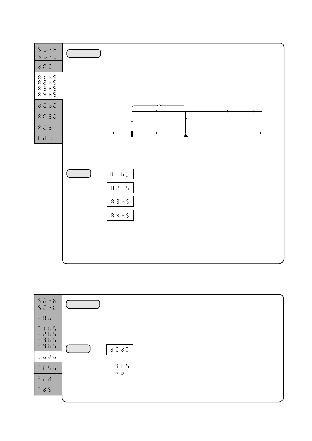
2.3 Setting of alarm 1 to 4 hysteresis allowances
Explanation
Setting
The hysteresis is to provide an allowance for the alarm ON and OFF operating
points. Normally, the hysteresis is used for the prevention of chattering
(disorder of alarm). Also it is used for positively shifting the ON and OFF
operating points.
Example) Where a hysteresis allowance of 20°C is provided for an upper limit
absolute alarm with the alarm set value of 80°C:
Hysteresis allowance
Alarm ON
Alarm OFF
60°C
80°C
(Alarm set value)
When PV is rising : the alarm turns ON at 80°C.
When PV is falling: the alarm turns OFF at 60°C.
Alarm 1 hysteresis allowance setting
Alarm 2 hysteresis allowance setting
Alarm 3 hysteresis allowance setting
Alarm 4 hysteresis allowance setting
0 to 50% of the input range (engineering units)
If the alarm type is deviation alarm, the setting must be made so that the alarm
set value is greater than the hysteresis allowance.
2.4 DV differentiate specification........ D operation of PID is differentiated
for DV.
Explanation
Setting
The D action in the PID operation is differentiated for DV. The standard D
action in this unit is the PV differentiation (differentiation-preceding type PID).
The controllability may be improved by specifying the DV differentiation when
the ramp pattern is used.
DV differentiate specification
: DV differentiation
: PV differentiation (standard)
4-3
Page 55

2.5 AT SV mode......... Auto tuning in the low PV type
Explanation
(Standard AT) (Lower-PV type AT)
SV SV
Setting
Auto tuning for this unit is performed by Limit Cycle method, centering on a
set value (SV). In the low PV type auto tuning, the central point is lowered by
10%. This 10%-lower PV type is used even in the auto tuning, where the
measured value (PV) should be less than the set value (SV).
10%
PV
PV
AT SV mode
0: Standard AT (standard)
1: Low-PV type AT
2.6 AT PID mode ............Obtaining PI control parameter
Explanation
Setting
The AT PID mode is used to obtain a parameter for the PI control in the auto
tuning. However, the auto tuning in the standard status of this unit will seek a
parameter for the PID control.
AT PID mode
0: Parameter for PI control is obtained.
1: Parameter for PID control is obtained. (standard)
4-4
Page 56

2.7 Transmission write Protect ...... The SV change via transmission is
inhibited.
Explanation
Setting
A change of the set value (SV) via transmission is inhibited. (The inhibition of
a set value change from the keyboard can be accomplished with the setting
lock ( ) parameter.)
Transmission write Protect
0: A change of SV via transmission is allowed. (standard)
1: A change of SV via transmission is inhibited.
4-5
Page 57
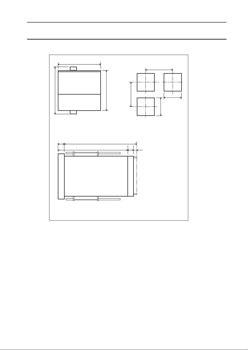
SECTION 5 INSTALLATION AND WIRING
1 Outline Diagrams
96
115
PUSH OPEN
Fuji
Electric PVX
12
173.5
154
Pannel hole center distance
100(135*)
96
116
*) The hole center distance is 135 mm in
the case of T-link transmission type.
(T-type: See the 12th column in CODE
SYMBOLS,)
12.5 7
+0.8
-0
92
92
+0.8
-0
2 Installation
2.1 Appropriate locations for installation
Like ordinary electronic digital devices, the unit should be installed at a location where the
following requirements are fulfilled:
(1) The temperature is within the normal range, 0°C to 50°C, with small changes.
(2) The area is free from corrosive gases (sulfide gas and ammonia gas, in particular).
(3) The area is free from an excessively low or high humidity. (10 to 90 RH)
(4) The area is subject to very small mechanical vibration.(0.2 G or less. 10 to 60 Hz)
(5) The area is subject to very small amount of dust and soot.
(6) The area is less affected by electrical noise.
(7) The area is free from intensive magnetism.
5-1
Page 58

2.2 How to install the unit
(1) Install the unit with the rear part descending at 15 degrees or less.
(2) For the pannel, use 2mm thick steel plate.
(3) Insert the unit casing into the pannel hole.
(4) Use fixtures (attachments) to secure the upper and lower part of the unit.
Figure 5-1 How to install Figure 5-2 Installation angle
3 Wiring
Rear descending angle:
15 degrees or less
3.1 Cautions for wiring
• Install a power switch and fuses as required. (Rating of fuse: 250V, 1A)The power switch
and fuses are not provided for the unit.
• Use a specified compensation lead wire for connecting with the input thermocouple.
• For the resistance bulb input wire, select a lead wire with small resistance.
• To avoid the influence of induced noise on the cable connecting the input signal line,
power supply line, and the blind controller, the cable must be laid apart from the power
supply line and load lines.
• The input signal line and the output signal line must be separated from each other, using
shielded wires.
3.2 Noise control measures
• The measures, as listed below, should be taken where the external wiring is subject to
excessive noise.
If a contactor is connected as a load of the digital output such as the relay contact output
and the alarm output, additionally install a surge absorber to the contactor coil. Z-TRAP
(Specification: 220V AC, ENB461D-14A, manufactured by Fuji Electric)
• Where excessive noise is generated from the power supply, the additional installation of
an insulating transformer and the use of a noise filter are suggested.
(Example: Noise filter, ZMB22R5-11, manufactured by TDK)
• Twisting wiring is effective for the power supply line of instruments.
5-2
Page 59

+
4 to 20mA
or
SSR/SSC
–
3.3 For connection of load circuit
Use an additional auxiliary relay, since the operating life of the output relay will be shortened
with a full load, where the relay operation is frequently performed as in the proportional
operation.
In this case, the use of SSR or SSC-drive output type is recommended.
For an electromagnetic switch: a proportional period of 30 seconds or longer
For SSC or SSR : a proportional period of 1 second is a target value.
Contact output life span: Mechanical life of 30 million times or more (under no load)
Electrical life of 100 thousand times or more (at rated load)
3.4 Wiring for the input 1 to 5 VDC
Although 250-ohm resistors are supplied as an attachment in the input specification of 4 to
20mA DC, these resistors will not be required.
3.5 External wiring diagram
An external wiring diagram is shown in Figure 5-3.
MV1-1
MV1-2
MV1-COM
ALM1
ALM2
ALM-COM
AC1
1
2
3
4
5
6
(COM)
9
10
TS1
11
TS2
TS3
12
13
TS4
DO-RESET
14
DO-RUN/HOLD
15
18
ALM3/TS5
19
ALM4/TS6
20
ALM/TS-COM
21
22
23
24
DI-2
DI-2
DI-2
3
2
1
27
28
29
AO2
AO1
30
31
AO-COM
DI-RESET
32
DI-RUN
33
A
36
RTD
B
37
SC
38
39
40
++
TC
mV
–
–
––
4 to 20mA
V
++
250Ω
0.1%
AC2
GND
7
8
DO-COM
DO-END
16
17
25
26
0
DI-2
DI-COM
34
DI-HOLD
DI-ADVANCE
35
41
42
Figure 5-3 External Wiring Diagram
5-3
Page 60

SECTION 6 APPENDIX
1. Specifications
1.1 Input Section
(1) Input signal-manipulating range..Multi-range
mode
Range code setting mode is employed for the
thermocouple and resistance bulb inputs.(See Table
1)
Programmable scale mode is employed for DC
voltage and current inputs. (See Table 1)
(2) Specification and setting accuracy
• Thermocouple input, resistance bulb input, and
voltage input
±0.2% FS±1 digit (at 23°C)
where, B thermocouple 0 to 400°C±5%
R thermocouple 0 to 500°C±1%
• Current input
±0.5% FS±1 digit (at 23°C)
or ±0.3% FS±1 digit (when using high-precision
resistor)
(3) Temperature drift
• ±0.2% FS/10°C
(4) Indicating resolution
• Thermocouple input: 1°C or 0.1°C
• Resistance bulb input: 1°C or 0.1°C
(5) Cold junction compensation error
• ±1.0°C
(6) Input sampling period
• 100 msec
(7) Input impedance
• Thermocouple: 1 mega ohms or more
• Current input: Outside resistor 250 ohms
• Voltage input: 1 mega ohms or more
(8) Permissible signal source resistance
• Thermocouple: 250 ohms or less
• Voltage input: 1 k ohms or less
(9) Permissible wire resistance
• Resistance bulb : 10 ohms or less (per wire)
(10) Permissible input voltage
• Voltage input : within ±35 V
• Current input : within ±22 mA
• Other inputs : within ±13 V
(11) Noise elimination ratio
• Normal mode: 60 dB (50/60 Hz)
• Common mode : ±1°C on 220V AC to ground, at
(12) Digital filter
• First-order lag filter
• 0.0 to 120.0 seconds, resolution:0.1 second (0 :
(13) PV input correction
• ±50.0%
(14) Over-range and under-range
• To detectable outside the range of from –5% to
105% of FS
1.2 Output part
(1) Control output
• Relay contact output
Proportional period: 1 to 120 sec.
Contact capacity: 220V AC/30V DC, 3A
Min. switching current: 100mA (24V DC)
Mechanical life: 30 million times (100 times/
min)
Electrical life: 100 thousand times (rated load)
50/60 Hz
±1°C on 220V AC between
input and output, at 50/60 Hz
OFF)
(resistive load)
220V AC/30V DC, 1A
(inductive load)
• Voltage pulse output (SSR/SSC-drive output)
Proportional period: 1 to 120 sec.
ON voltage: 10V DC to 18V DC
OFF voltage: 0.5V DC or less
Max. current: 20 mA DC
• Current output (4 to 20mA DC)
Guaranty output range: 3.2mA DC to 20.8mA
Accuracy: ±2% FS
Linearity: ±2% FS
Resolution: ±0.1% FS
Follow-up speed: 0.1 sec. or less
Ripple current: P-P 0.2% FS or less (50 Hz or
Load resistance: 600 ohms or less
(2) Auxiliary analog output (Option)
• Number of points: 2 points max. (option)
• Output type: 0 to 10 V DC
Guaranty output range: 0V DC to 10.5 V DC (0
Accuracy: ±0.08% FS
Ripple voltage: P-P 0.08% FS or less (50 Hz or
Temperature drift: ±0.08% FS/10°C
Load resistance: 500 k ohms or more
• Supplementary function: Scaling function
available
• Output update interval: 100 msec.
cf. An accuracy of ±0.2% FS can be assured when
scaling 1 to 5 V DC output.
DC (–5 to 105%)
less)
to 105%)
less)
1.3 Digital input (Option)
16 V DC, 15 mA
Threshold voltage: 6 V min. 15 V max.
Input read interval: (a pulse input of 0.5 sec. or longer)
(1) External command input (4 points)
• RESET Program reset
• RUN Program run to start
• HOLD Program run to hold
• ADVANCE Advancing a segment
(2) Pattern select input (4 points)
• BCD input - 1 digit (23, 22, 21, and 20)
1.4 Digital output
• Output update interval : 100 msec.
(1) Alarm output (ALM1 and ALM2) (Standard)
• Relay output × 2 points 1a contact
Contact capacity: 220 V AC/30 V DC, 1 A
Min. switching current: 100 mA(24 V DC)
Mechanical life : 12 million times (20 times/min)
Electrical life: 60 thousand times (rated load, 20
(2) Expanded alarm output (ALM3 and ALM4) (Option)
• Open collector output × 2 points
• 24 V DC, 50 mA or less
(3) Time signal (TS1, TS2, TS3, and TS4) (Option)
• Open collector output × 4 points
• 24 V DC, 50 mA or less
(4) Expanded time signal (TS5 and TS6) (Option)
• Open collector output × 2 points
• 24 V DC, 50 mA or less
(5) Status signal output (Option)
• Open collector output × 3 points
• 24 V DC, 50 mA or less
RESET Reset state
RUN/HOLD Program running/holding state
END Program ending state
(resistive load)
220 V AC/30 V DC, 0.3 A
(inductive load)
times/min)
1.5 Communication facility (Option)
6-1
Page 61

Not provided
1.6 Loader interface (Option)
• RS-232C (3-line system)
• Transmission mode: Half duplex bit serial
• Synchronization mode: Start-stop synchronization
• Coding type: ASCII code, data length: 8-bit
• Transmission rate: 9600 bps
• No. of units connectable: 1 unit max.
• Transmission distance: Overall distance 5 m max.
Odd-parity
1.7 Display section
(1) Display mode
• 7-segment, 4-digit × 3, red and green LED
• LED, red and green
(2) Display character
• 7.62 mm high and 4.19 mm wide
(3) Display update interval 100 msec
1.8 Keyboard section
(1) Key switch
• 10 sets
(2) Function
• Parameter setting and the unit operation
1.9 Setting resolution
• Thermocouple inpu: 1°C or 0.1°C (1°F or 0.1°F)
• Resistance bulb input: 1°C or 0.1°C (1°F or 0.1°F)
1.10 Controllability
Basic PID type (speed type)
(1) Proportional zone (P)
• 0.0 to 999.9, 2-position operation with P=0
(2) Integration time
• 0 to 3200 sec., I-operation breaks with I=0
(3) Differentiation time
• 0 to 900 sec., D-operation breaks with D=0
1.11 Program storage capacity
(1) Number of program patterns
• 9 patterns
(2) No. of segments in a pattern
• 20 segments
(3) Multimemory (PID grouping)
• Nine
(4) Number of program repetitions
• 99 times max.
(5) Memory backup: Lithium cell
• Room temperature 0 to 40°C, unused state: 5
years or longer
• Room temperature 40°C or higher, unused state:
1 year or longer
1.12 Power supply
(1) Power voltage
• 100 V AC to 240 V AC, free power supply
(2) Power voltage fluctuation
• Within the range of from +10% to –15%
(3) Power frequency
• 50/60 Hz
(4) Power consumption
• For 100 V AC: 20 VA or less
• For 220 V AC: 30 VA or less
1.13 Normal operating conditions
(1) Room temperature
• 0 to 50°C
(2) Environmental humidity
• 90% RH or less (No condensation must be
produced)
(3) Installation profile
• To be installed with the rear end descending at
15 degrees or less
(4) Vibration
• 10 to 70 Hz, 1 G or less
(5) Impact
• 3 G or less
(6) Warm-up
• 30 min. or longer
(7) Insulating resistance
• Power terminal - Grounding terminal
• Input terminal - Grounding terminal
• Output terminal - Grounding terminal
• Contact terminal - Grounding terminal
• Input terminal - Power terminal
• Output terminal - Power terminal
• Contact terminal - Power terminal
• Output terminal - Input terminal
• Contact terminal - Input terminal
• Contact terminal - Output terminal
(8) Dielectric strength
• Power voltage - Grounding terminal : 1500 V AC, for
• Input terminal - Grounding terminal
• Output terminal - Grounding terminal
• Contact terminal - Grounding terminal
• Input terminal - Power terminal
• Output terminal - Power terminal
• Contact terminal - Power terminal
• Output terminal - Input terminal
• Contact terminal - Input terminal
• Contact terminal - Output terminal
500 V DC,
20 M ohms
or more
1 min.
500 V AC,
for 1 min.
Leak
current: 1.5
mA or less
1.14 Transport and storage conditions (in
packed state)
(1) Storage temperature
• –10 to 60°C
(2) Environmental humidity
• 90% RH or less (No condensation must be
produced)
(3) Vibration
• 10 to 70 Hz, 2 G or less
(4) Impact
• 30 G or less
1.15 Structure
(1) Material
• Plastic housing (ABS-M-GG)
(2) Fire retardancy
• UL94V-0 or equivalent
(3) Color
• Munsell value : N1.5 (black) or equivalent
(4) Outline dimensions
•(W × H × D) mm: 96 × 96 × 170
(5) Net Weight
• Approximately 1 kg.
(6) Installation mode
• Insertion into panel hole
(7) External terminals
• Screwed terminal M3.5
(8) Dust-proof cover
• PMMA-M-GE (Transparent with no color)
(Option)
6-2
Page 62

2. [Program Pattern Preparation Form]
Set value
[Programming map]
Segment
Display
Set
Set
value
value
Pattern
PID number
Alarm 1 set value
Alarm 2 set value
Alarm 3 set value
Alarm 4 set value
Time signal 1
ON time
Time signal 1
OFF time
Time signal 2
ON time
Time signal 2
OFF time
Time signal 3
ON time
Time signal 3
OFF time
Time signal 4
ON time
Time signal 4
OFF time
Time signal 5
ON time
Time signal 5
OFF time
Time signal 6
ON time
Time signal 6
OFF time
Guarantee soak
Yes/No
Guarantee soak
type
PV start
Number of times of
cyclic operation
Link pattern
number
Time
Time
Setting
range
0 to 10000
0.0 to 99.59
1 to 9
0 to 10000
0 to 10000
0 to 10000
0 to 10000
0.0 to 99.59
0.0 to 99.59
0.0 to 99.59
0.0 to 99.59
0.0 to 99.59
0.0 to 99.59
0.0 to 99.59
0.0 to 99.59
0.0 to 99.59
0.0 to 99.59
0.0 to 99.59
0.0 to 99.59
0: Upper and
lower
1: Lower
2: Upper
,
1 to 99
,
1 to 9
Notation
Engineering
units
hr:min,
min:sec
No.
Alarm
value
Alarm
value
Alarm
value
Alarm
value
hr:min,
min:sec
hr:min,
min:sec
hr:min,
min:sec
hr:min,
min:sec
hr:min,
min:sec
hr:min,
min:sec
hr:min,
min:sec
hr:min,
min:sec
hr:min,
min:sec
hr:min,
min:sec
hr:min,
min:sec
hr:min,
min:sec
YES/NO
YES/NO
OFF or
1 to 99
OFF or
1 to 99
Time
1/11 2/12 3/13 4/14 5/15 6/16 7/17 8/18 9/19 10/20
6-3
Page 63

3. Paremeter List
Channel Code Name Setting Range Notation
ProG Ch
Pid Ch
SV
TM
PID
ALM1
ALM2
ALM3
ALM4
T1ON
T1OF
T2ON
T2OF
T3ON
T3OF
T4ON
T4OF
T5ON
T5OF
T6ON
T6OF
GS
GSTP
PVST
CYCL
LINK
P
I
D
GAP
MV-H
MV-L
REV
KNL
AR
MAN
Set value
Segment time
PID group number
Alarm 1 set value
Alarm 2 set value
Alarm 3 set value
Alarm 4 set value
Time signal 1
ON Time
Time signal 1
OFF Time
Time signal 2
ON Time
Time signal 2
OFF Time
Time signal 3
ON Time
Time signal 3
OFF Time
Time signal 4
ON Time
Time signal 4
OFF Time
Time signal 5
ON Time
Time signal 5
OFF Time
Time signal 6
ON Time
Time signal 6
OFF Time
Guarantee soak
Yes/No
Guarantee soak
Upper/Lower limit
PV start Yes/No
Number of cyclic
operations
Link pattern
number
Proportional zone
Integration time
Differentation time
Blind zone
MV upper limit
MV lower limit
Reverse
specification
Non-linear gain
Integration break
point setting
Manual setting
0-100% of input range
0.00~99.59
1-9
0-100% of input range
0-100% of input range
0-100% of input range
0-100% of input range
0.00~99.59
0.00~99.59
0.00~99.59
0.00~99.59
0.00~99.59
0.00~99.59
0.00~99.59
0.00~99.59
0.00~99.59
0.00~99.59
0.00~99.59
0.00~99.59
0-1
0-2
0-1
0-99
0-19
0.0~999.9
0-32000
0.0-900.0
0-50% of input range
–5.0-105.0
–5.0-105.0
0-1
–32767-32767
0-100% of input range
–50.0-50.0
Engineering unit
hr:min
(min:sec)
Number
Alarm display 1
Alarm display 2
Alarm display 3
Alarm display 4
hr:min
(min:sec)
hr:min
(min:sec)
hr:min
(min:sec)
hr:min
(min:sec)
hr:min
(min:sec)
hr:min
(min:sec)
hr:min
(min:sec)
hr:min
(min:sec)
hr:min
(min:sec)
hr:min
(min:sec)
hr:min
(min:sec)
hr:min
(min:sec)
YES/NO
YES/NO
OFF/numeral
OFF/numeral
%
Second
Second
Engineering unit
%
%
YES/NO
%
Engineering unit
%
Initial value
– – – –
– – – –
– – – –
– – – –
– – – –
– – – –
– – – –
– – – –
– – – –
– – – –
– – – –
– – – –
– – – –
– – – –
– – – –
– – – –
– – – –
– – – –
NO
NO
OFF
OFF
8.0%
240 sec.
40 sec.
0%
105.0%
–5.0%
YES
0.0%
100.0%
0.0%
Remarks
1
0
6-4
Page 64

Channel Code Name Setting Range Notation
SyS Ch
PVT
PV input type
PVU
PV unit
PVF
PV full scale
PVB
PV base scale
Decimal point position
PVD
Filter time constant
TF
PV shift
SFT
Input type code table
0-1
–999-9999
–999-9999
0-3
0.0-999.0
–50.0-50.0% of input
Second
Engineering unit
range
Start mode
STM
Output proportion
C1
0-1
0~120
Second
period
PSET
BURN
Preset MV value
Output set value at
–5.0-105.0
–5.0-105.0
%
%
burnout
AL1T
AL2T
AL3T
AL4T
AO1T
AO1R
Alarm 1 type
Alarm 2 type
Alarm 3 type
Alarm 4 type
AO1 output type
AO1 output range
0-18
0-18
0-18
0-18
0-2
0-2
type
AO1F
AO1B
AO2T
AO2R
AO1 full scale
AO1 base scale
AO2 output type
AO2 output range
0.0-100.0
0.0-100.0
0-2
0-2
%
%
type
AO2F
AO2B
TMU
TMDT
ENDT
GS-H
AO2 full scale
AO2 base scale
Time unit
Time display type
END signal output
time
Guarantee soak
upper limit set
0.0-100.0
0.0-100.0
0-1
0-1
0.00~99.59
–50.0-50.0% of input
range
%
%
hr:min
(min:sec)
Engineering unit
value
GS-L
Guarantee soak
lower limit set
–50.0-50.0% of input
range
Engineering unit
value
GSTM
Guarantee soak
max. wait time
0.00~99.59
hr:min
(min:sec)
Initial value
22
1000
0000
2.0 sec.
0%
20 sec
0.0%
0.0%
100.0%
0.0%
100.0%
0.0%
0:00
5%
5%
99:59
Remarks
0
Either one will be
displayed depending
on PV input type.
0
0
To be displayed on relay
drive or SSR drive.
1
To be displayed if
expanded alarms
2
(3,4) are provided.
3
4
0
To be displayed if
auxiliary signal
0
output is provided.
1
To be displayed if
2 points of
0
auxiliary signal
output are
provided.
0
0
Display format is
either "hr:min" or
"min:sec" depending
on time unit setting.
Display format is
either "hr:min" or
"min:sec" depending
on time unit setting.
EXP Ch
Station number
STN
Set value upper limit
SV-H
Set value lower limit
SV-L
MV variation limit
DMV
Alarm 1 hysteresis
A1HS
Alarm 2 hysteresis
A2HS
Alarm 3 hysteresis
A3HS
Alarm 4 hysteresis
A4HS
DV differentiate
DVDV
specification
AT SV mode
ATSV
AT PID
PID
specification
Transmission
TDS
write disable
0-99
0-100% of input range
0-100% of input range
–5.0-105.0
0-50% of input range
0-50% of input range
0-50% of input range
0-50% of input range
0-1
0-1
0-1
0-1
6-5
Engineering unit
Engineering unit
%
Engineering unit
Engineering unit
Engineering unit
Engineering unit
YES/NO
YES/NO
100%
0%
105.0%
0.5%
0.5%
0.5%
0.5%
NO
NO
0
To be displayed if Tlink transmission is
provided.
To be displayed if alarms
3 and 4 are provided.
0
1
Page 65
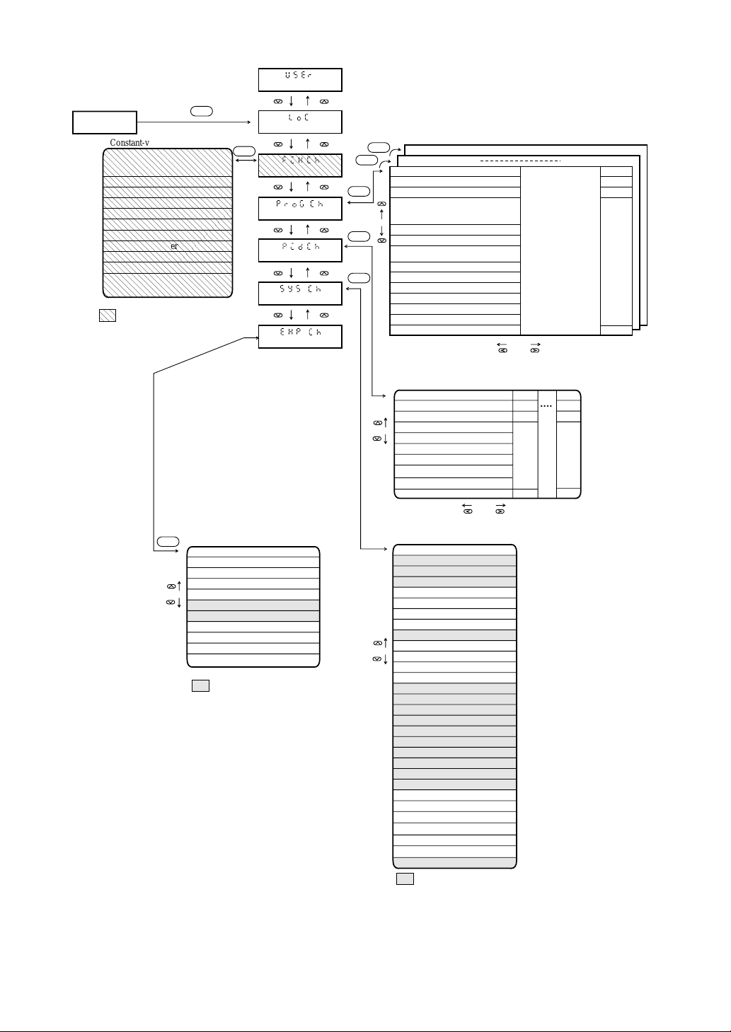
User level
Operating status
display
Constant-value mode channel
ALM1
ALM4
Pidn
P
I
d
GAP
Mv-h
Mv-L MV lower limit
rEv
KnL
Ar
MAn
To be displayed only in the
constant-value mode.
SEL
Alarm 1 set value
to
Alarm 4 set value
Proportional zone
Integration time
Differentiation time
Dead zone
MV upper limit
Reverse operation specification
Non-linear gain
Integration cut point
Manual reset
Setting lock
SEL
Constant-value channel
Program pattern channel
PID channel
Setup channel
Expert channel
SEL
SEL
SEL
PTN
PTN
Segment 1
Set value
Time
Pidn
Alarm 1 set value
ALM1
Alarm 4 set value
ALM4
T1on
Time signal 1 ON time
T1of
Time signal 1 OFF time
Program pattern channel
to
to
Time signal 6 ON time
T6on
Time signal 6 OFF time
T6of
GS
Guarantee soak Yes/No
GSTP
Guaranrtee soak type
PV start specification
PvST
CyCL
No. of times of cyclic operation
Link
Link pattern number
No.1 No.2 No.9
Proportional zone
P
Integration time
I
d
Differentiation time
GAP
Dead zone
MV-h
MV upper limit
MU-L
MU lower limit
rEv
Reverse operation specification
KnL
Non-linear gain
Ar
Integration cut point
MAn
Manual reset
PID channel
Pattern 9
P
I
d
MAn
Pattern 1
MAn
P
I
d
Segment 20
Set value
Time
Pidn
Link
SEL
Expert channel
Sv-h
Set value upper limit
Sv-L
Set value lower limit
dMv
Movement variation limit
Alarm 1 hysteresis
A1hs
Alarm 2 hysteresis
A2hs
A3hs
Alarm 3 hysteresis
Alarm 4 hysteresis
A4hs
dvdv
DV differentiate specification
ATSv
AT ST mode
Pid
AT PID mode
Tds
Transmission write inhibit
To be displayed only when an
optional item is installed.
PvT
PvU
PvF
Pvb
Pvd
TF
SFT
STM
C1
PSET
bUrn
AL1T
AL2T
AL3T
AL4T
AO1T
AO1r
AO1F
AO1b
AO2T
AO2r
AO2F
AO2b
TMU
TMdT
EndT
GS-h
GS-L
GSTM
STn
Figure 6-1 Parameter Map
System setup channel
PV input type
PV unit
PV fullscale
PV base scale
Position of deciaml point
Filter time constant
PV shift
Start mode
Output proportional period
Preset MV value
Burnout MV value
Alarm 1 type
Alarm 2 type
Alarm 3 type
Alarm 4 type
AO1 output type
AO1 output range
AO1 full scale
AO1 base scale
AO2 output type
AO1 output range
AO1 full scale
AO1 base scale
Time unit
Time display type
END signal output time
Guarantee soak upper limit
Guarantee soak lower limit
Guarantee soak max. wait time
Station number
To be displayed only when
an optional item is installed.
6-6
 Loading...