

Page 1

Instruction Manual
PORTAFLOW C
PC LOADER SOFTWARE
INSTRUCTION MANUAL
INF-TN5A1784-E
Page 2

Contents
1. OUTLINE ·········································································································································································1
1.1. COPYRIGHT OF THIS SOFTWARE·························································································································1
1.2. GENERAL ·································································································································································1
1.3. SYSTEM REQUIREMENTS······································································································································1
1.3.1. PC main unit ·······················································································································································1
1.3.2. Memory capacity·················································································································································1
1.3.3. Interface······························································································································································1
1.3.4. OS ···································································································································································1
1.4. SCOPE OF DELIVERY ·············································································································································1
2. INSTALLING OF SOFTWARE ·········································································································································2
2.1. Installing Microsoft Windows Installer 3.1··················································································································2
2.2. Installing Microsoft .NET Framework Version 2.0 ······································································································5
2.3. Installing of USBExpress···········································································································································7
2.4. Device Recognition ···················································································································································9
2.5. Installing of Loader Software···································································································································12
3. Communication Specification·········································································································································15
4. Startup Method ······························································································································································16
4.1. Version ····································································································································································17
5. Setting Screen ·······························································································································································18
6. Measurement·································································································································································19
7. Logger data····································································································································································21
8. Site Setting ····································································································································································22
8.1. Site Memory ····························································································································································23
8.2. Establish Setting······················································································································································24
8.3. Output unit/Output control ·······································································································································26
9. Maintenance ··································································································································································27
9.1. RECEIVED SIGNAL················································································································································28
9.2. Adjustment of graph scale ·······································································································································29
10. Flow velocity profile······················································································································································30
10.1. Flow velocity profile···············································································································································31
11. QUIT ············································································································································································33
12. UNINSTALLING SOFTWARE······································································································································33
13. APPENDIX···································································································································································34
13.1. If an USB device is recognized as a COM port ·····································································································34
13.1.1. How to check ··················································································································································34
13.1.2. Restoration procedure ····································································································································36
13.1.3. Check after installation····································································································································40
Thank you very much for purchasing our PortaFlow-C Loader Software.Read this instruction manual carefully before using
this personal computer communication software.
(*) Caution: This manual is subject to change without prior notice.
-i-
Page 3

1. OUTLINE
1.1. COPYRIGHT OF THIS SOFTWARE
The copyright of this software belongs to Fuji Electric Systems Co., Ltd.No part of this software may be reproduced or
transmitted in any form.
1.2. GENERAL
Using this software, you can set, read and display relevant graphs of the PortaFlow-C on your PC with ease.
1.3. SYSTEM REQUIREMENTS
1.3.1. PC main unit
AT compatible-type with CPU Pentium IV 1 GHz/Celeron 1 GHz or more installed, display resolution of 1024 × 768, and
use of small font recommended and CD-ROM drive.
1.3.2. Memory capacity
128 MB or more (256 MB or more recommended) [52 MB memory or more for free space required]
1.3.3. Interface
More than one USB port is necessary.
1.3.4. OS
Microsoft Windows 2000 Professional (SP4 or more)
Microsoft Windows XP Professional (SP2 or more)
Microsoft Windows Vista Susiness: Use it in Basic mode.
It is not avairable for Windows Aero.
Microsoft Windows 7 (Home Premium, Professional)
CD-ROM: 1
Setup disk: Installing software to PC
Instruction manual
1.4. SCOPE OF DELIVERY
-1-
Page 4
2. INSTALLING OF SOFTWARE
2.1. Installing Microsoft Windows Installer 3.1
Note) this software is not required for PC which already installed Windows installer.
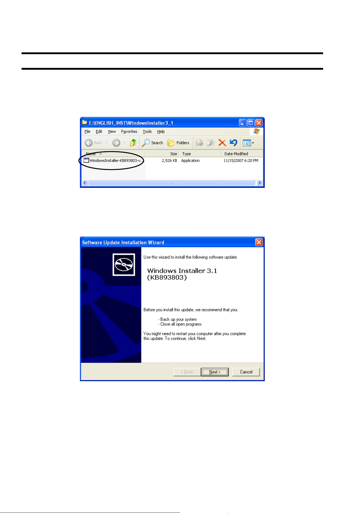
(1) Insert the setup disk into the drive, and double-click “WindowsInstaller-KB893803-v2-x86.exe” in the
WindowsInstaller3.1 folder.
Fig. 2-1 File Installation
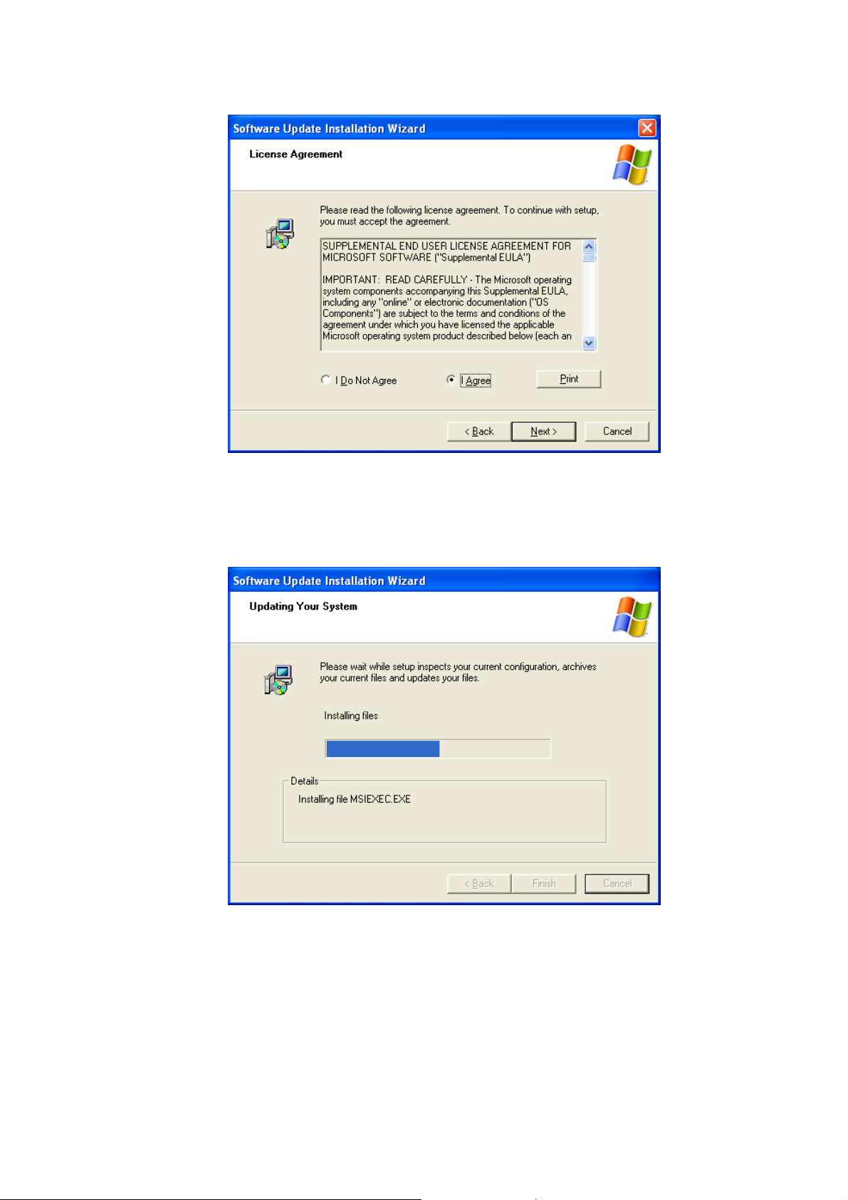
(2) Setting wizard will start up. Click the [Next] button.Click the [Cancel] button to cancel the installation.
Fig. 2-2
Wizard screen
-2-
Page 5
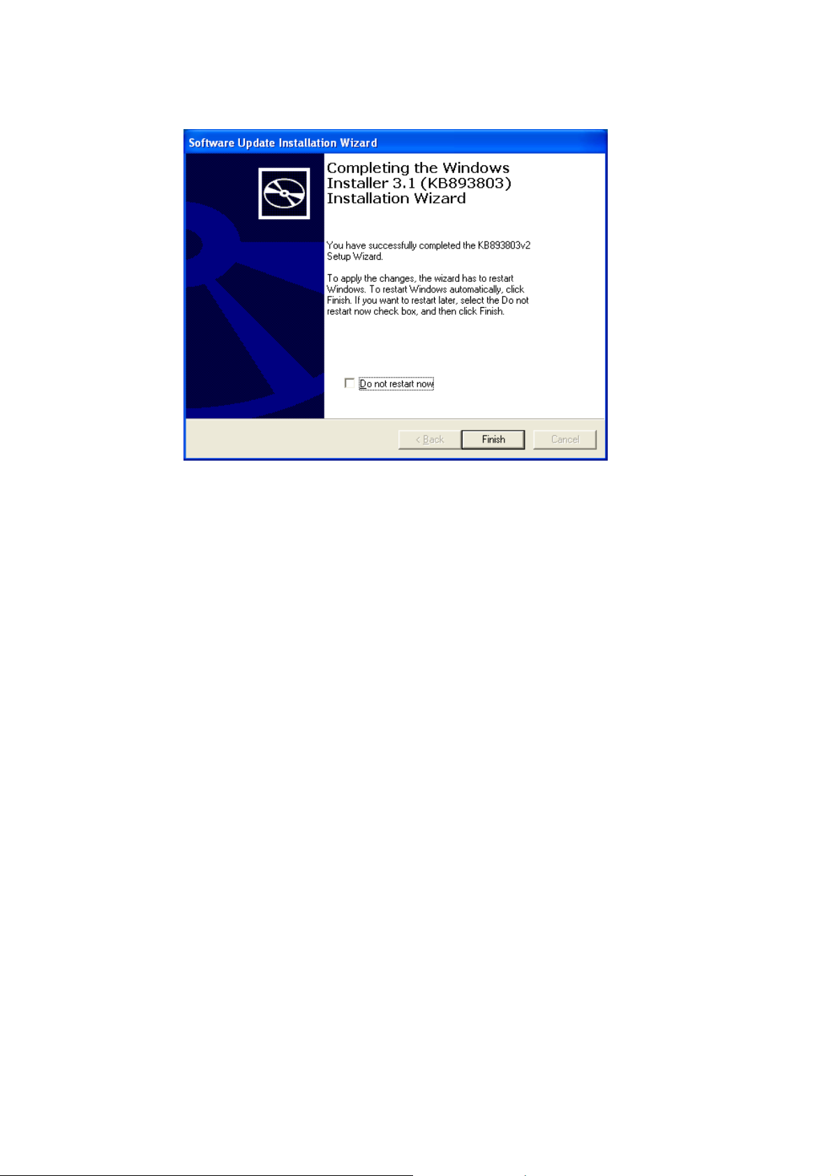
There is a query about the License Agreement, check the [I Agree] and click the [Next] button.Click the [Cancel]
(3)
button to cancel the installation.The [Back] and the [Print] buttons are not used here.
Fig. 2-3 License Agreement screen
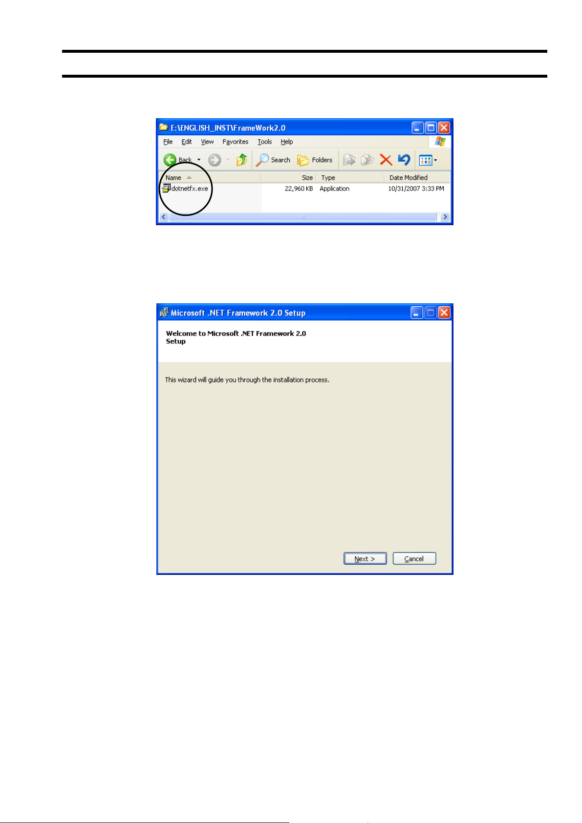
(4) Screen for updating your system is displayed.Wait until installation is completed.
Fig. 2-4 Updating Your System screen
-3-
Page 6
After installation, the installation complete screen appears. Check the “Do not restart new”, click the [Finish]
(5)
button.That is the end of installation for Microsoft Windows Installer 3.1.
Fig. 2-5 Install Complete
-4-
Page 7
2.2. Installing Microsoft .NET Framework Version 2.0
(1) Insert the setup disk into the drive, and double-click “dotnetfx.exe” in the FrameWork2.0 folder.
Fig. 2-6 File Installation
(2) Setting wizard will start up. Click the [Next] button. Click the [Cancel] button to cancel the installation.
Fig. 2-7 Setup wizard screen
-5-
Page 8
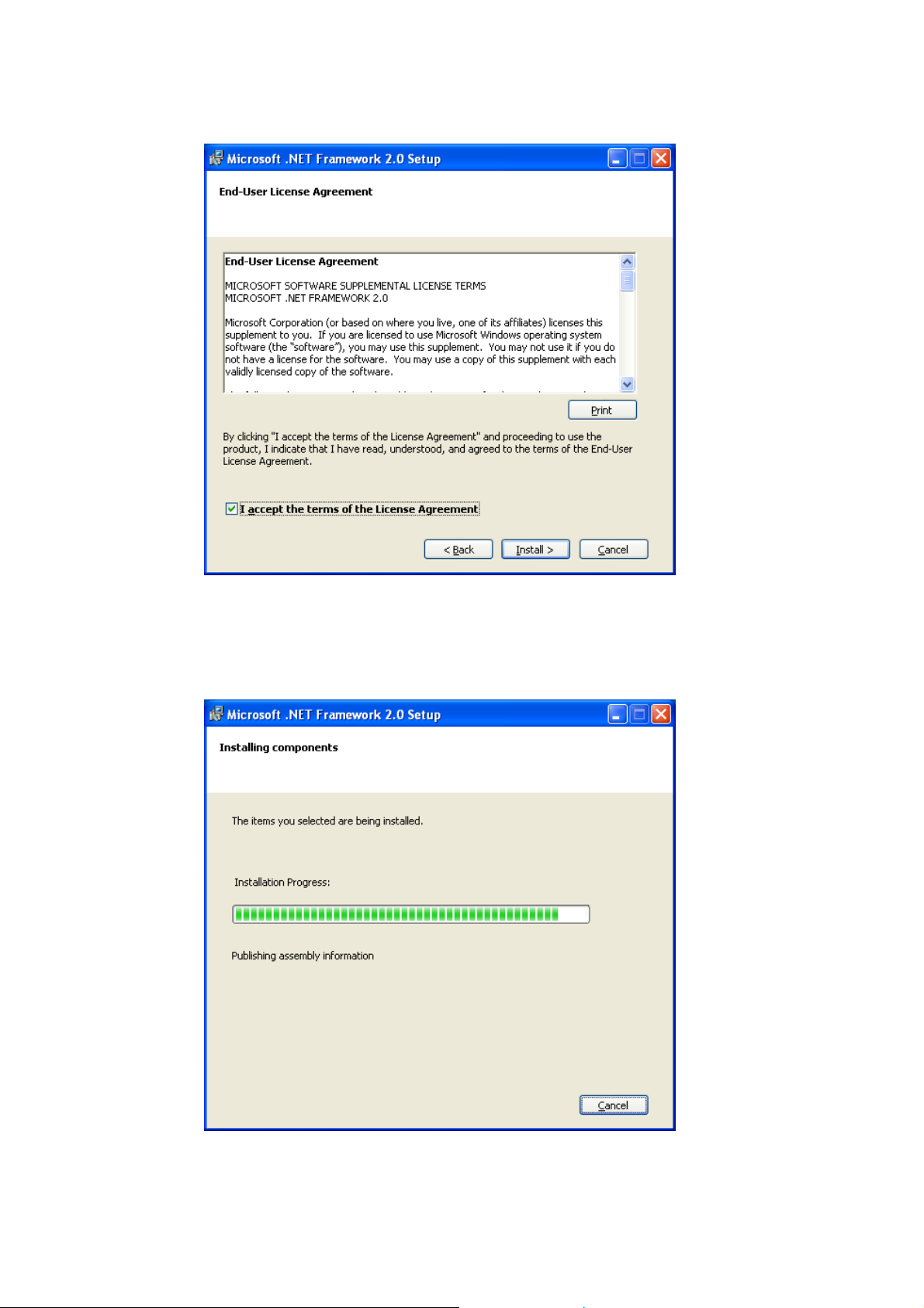
There is a query about the End-User Liecemse Agreement, check the [I accept the terms of the License Agreement]
(3)
and click the [Install] button. Click the [Cancel] button to cancel the installation. The [< Back] and the [Print] buttons
are not used here.
Fig. 2-8 End-User License Agreement screen
(4) Screen is displayed to confirm installation. Click the [Cancel] button to cancel the installation.
Fig. 2-9 Installation confirmation screen
-6-
Page 9
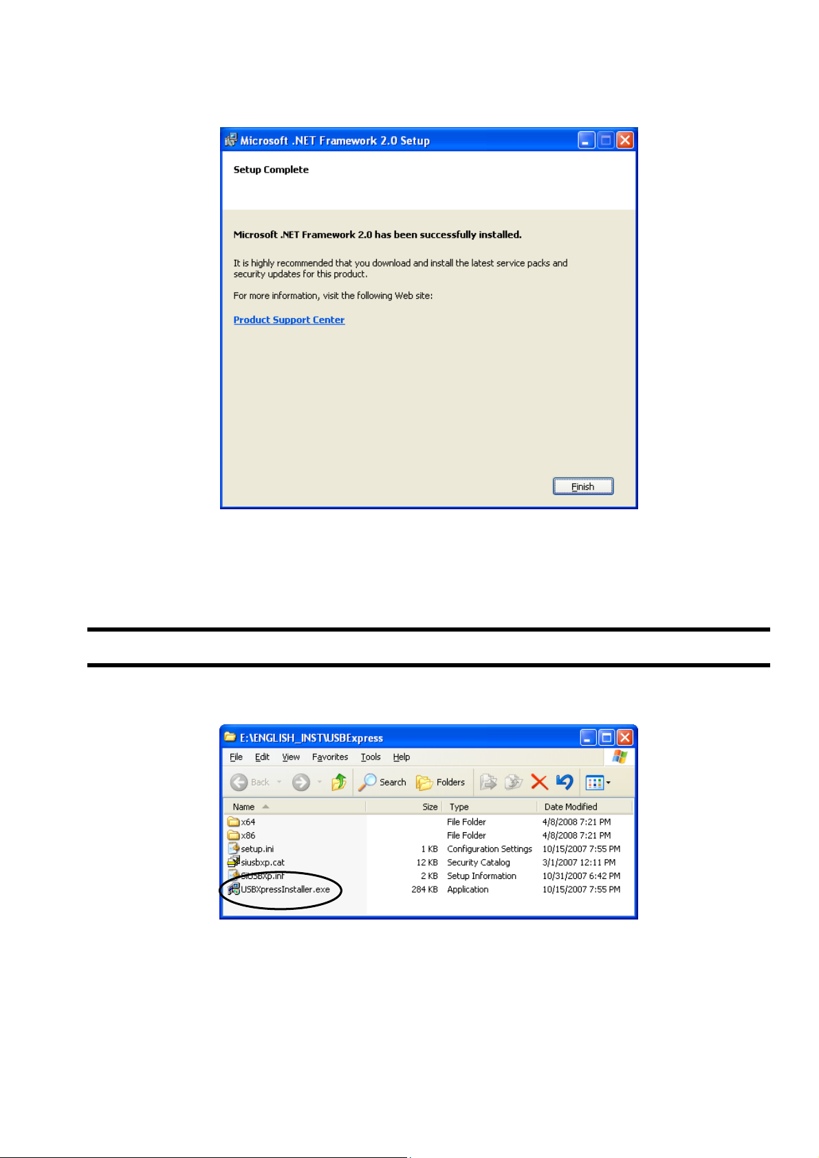
After installation, the Completion of Process Setting screen appears. Click the [Finish] button, and the installation of
(5)
Microsoft .NET Framework Version 2.0 is completed.
Fig. 2-10 Setup Complete
2.3. Installing of USBExpress
(1) Insert the setup disk into the drive, and double-click “USBXpressInstaller.exe” in the USBExpress folder.
Fig. 2-11 File Installation
-7-
Page 10
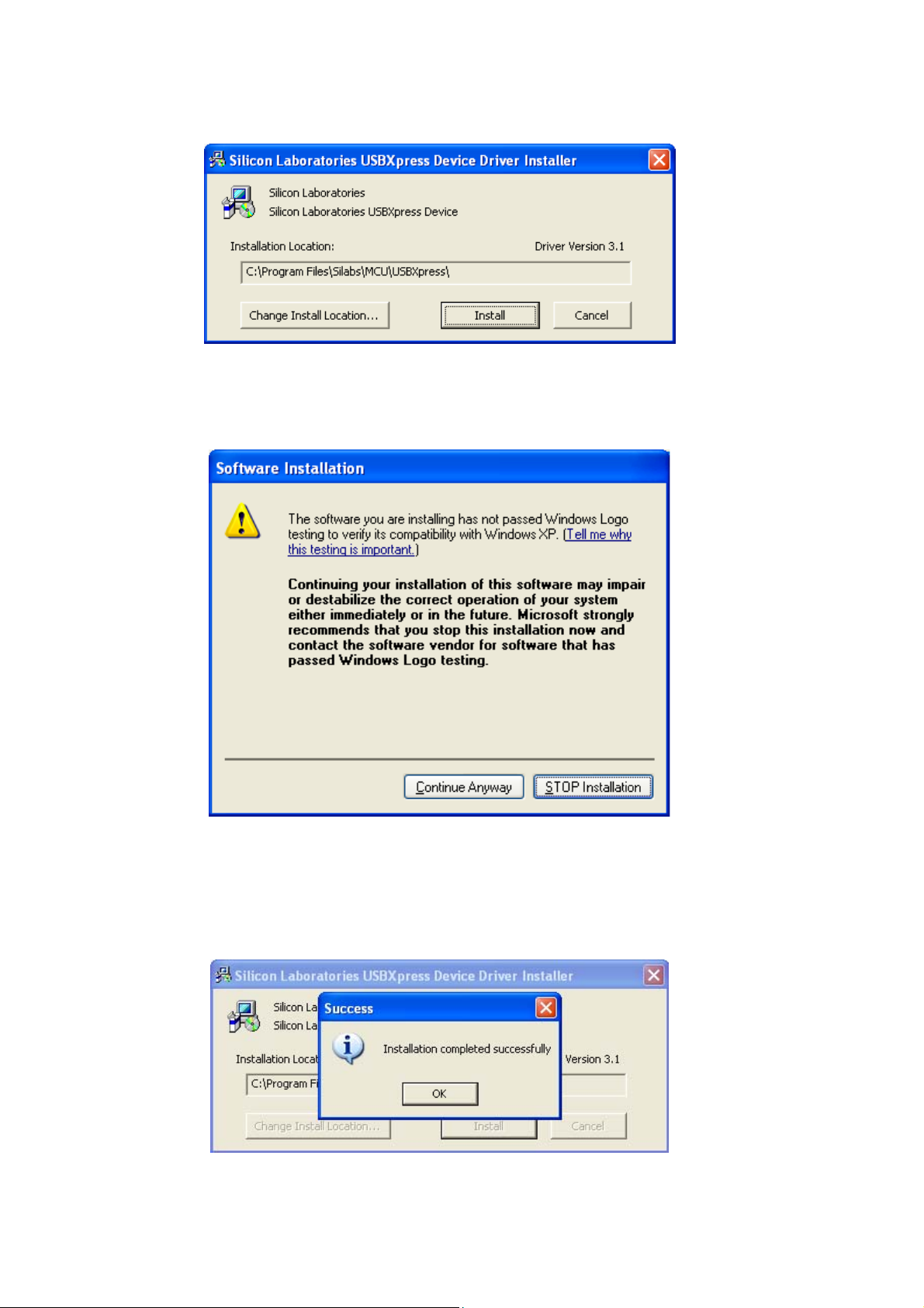
Installer will start up. Click the [Install] button. Click the [Cancel] button to cancel the installation. The [Change Install
(2)
Location] button is not used.
Fig. 2-12 Installer screen
(3) If the warning on the windows logo test is indicated, click the [Continue Anyway] button to continue the operation.
Fig. 2-13 Software Instration screen
(4) After installation, the installation complete screen appears. Click the [OK] button, and the installation of USBExpress
is completed.
Fig. 2-14 Installation complete screen
-8-
Page 11
2.4. Device Recognition
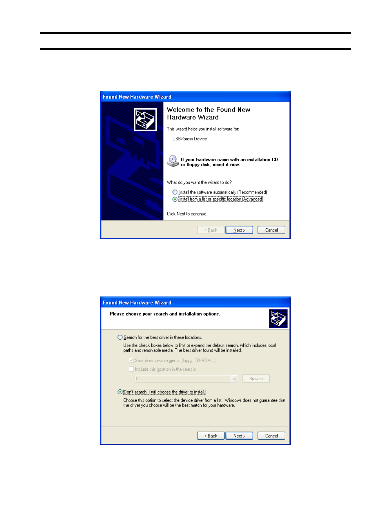
(1) After the setup in “Section 2.1, 2.2 and 2.3” are normally completed, connect the PortaFlow-C to the PC with USB
cable. Found New Hardware Wizard will start up. Check the [Install from a list or specific location (Advanced) (S)]
button and click the [Next] button. Click the [Cancel] button to cancel the installation.
Fig. 2-15 Found New Hardware Wizard
(2) The Found New Hardware Wizard appears. Check the [Don’t search. I will choose the driver to install (D)] and click
the [Next] button. Click the [Cancel] button to cancel the installation. The [Back (B)] button is not used here.
Fig. 2-16 Found New Hardware Wizard 2
-9-
Page 12
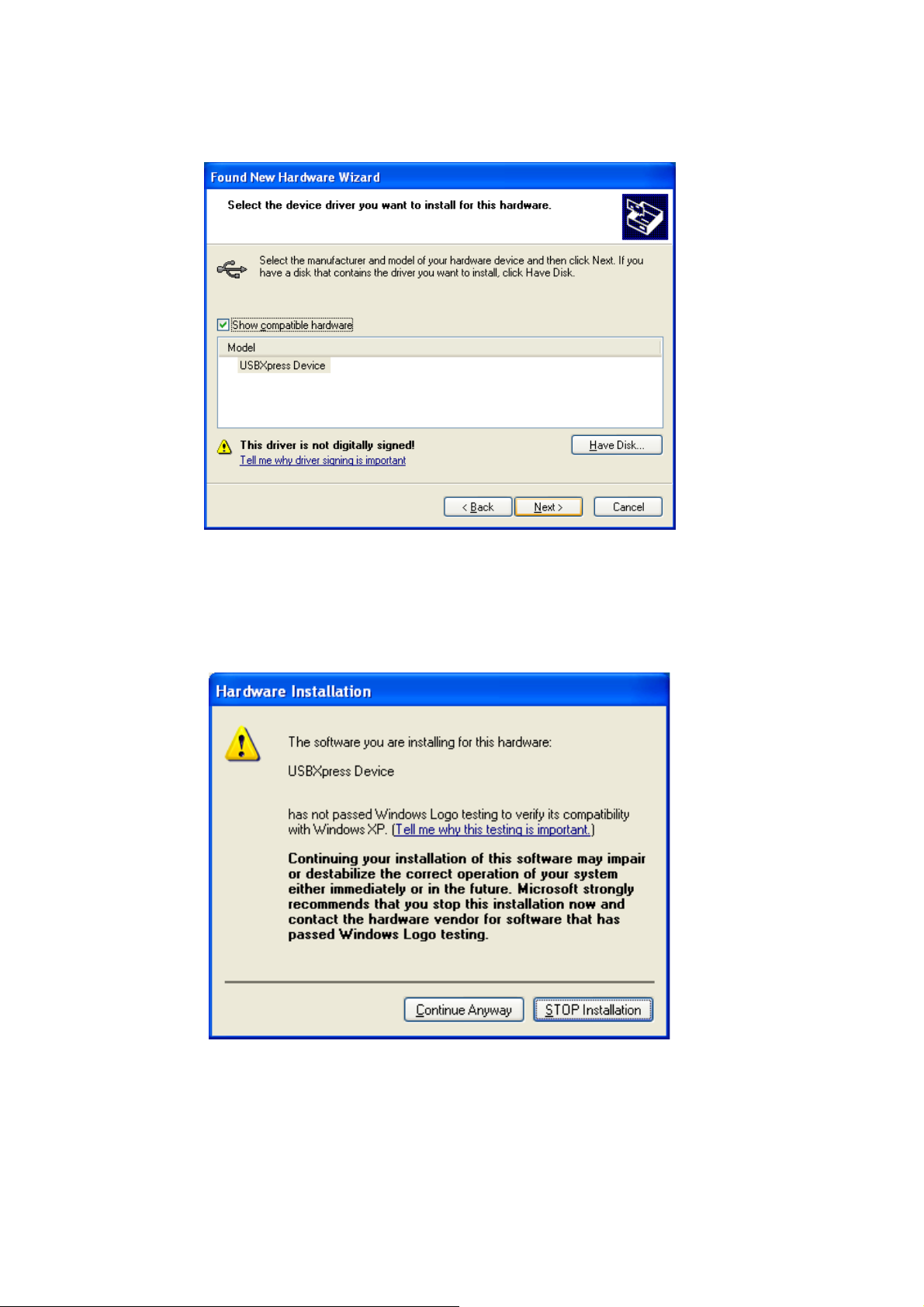
The Found New Hardware Wizard appears. Select the device driver to be installed for this hardware. Select the
(3)
[USBExpress Driver] indicated in the [Model], and click the [Next] button. Click the [Cancel] button to cancel the
installation. The [Back] button is not used here.
Fig. 2-17 Found New Hardware Wizard 3
(4) If the warning on the windows logo test is indicated, click the [Continue Anyway] button to continue the operation.
Screen is displayed to confirm installation. Wait until installation is completed.
-10-
Page 13
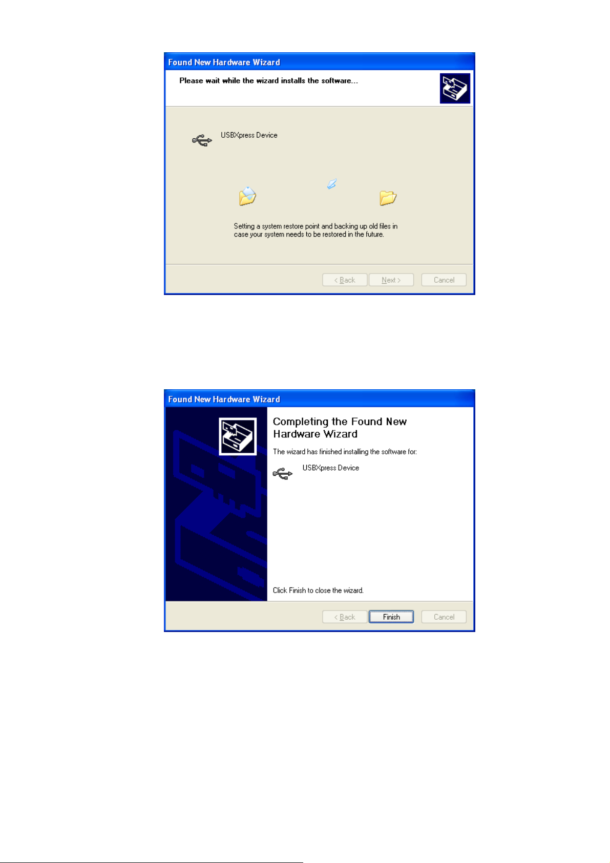
Fig. 2-18 Installation confirmation screen
(5) After installation, the installation complete screen appears. Click the [OK] button, and the device recognition is
completed.
Fig. 2-19 Installation complete screen
-11-
Page 14

2.5. Installing of Loader Software
(1) Insert the setup disk into the drive, and double-click “PFC_SETUP_ENG.msi”.
Fig. 2-20 File Installation
(2) Setting wizard will start up. Click the [Next] button. Click the [Cancel] button to cancel the installation.
Fig. 2-21 Setup wizard screen
-12-
Page 15

There is a query about selection of installation folder. Click the [Next] button to install the software in that folder. Click
(3)
the [Cancel] button to cancel the installation. The [Back (B)], the [Print (P)] and the [Disk range (D)] buttons are not
used here.
Fig. 2-22 Select installation folder screen
(4) Screen is displayed to confirm installation. Click the [Next] button to execute the installation. Click the [Cancel] button
to cancel the installation. The [Back (B)] button is not used here.
Fig. 2-23 Installation confirmation screen
-13-
Page 16

Execute installation. Click the [Cancel] button to cancel the installation.
(5)
Fig. 2-24 Installing screen
(6) The Installation Complete screen is displayed. Click the [Close] button to exit the installation screen.
Fig. 2-25 Installation complete screen
(7) After installation, the start menu and the application (“PortaFlow-C”) that has been installed in the desktop are
created.
-14-
Page 17

3. Communication Specification
See the following table for communication specifications.
(1) Genearal specification
Table 3-1 Communication specifications
Item Specifications
Standard (Electrical specification) USB communication
Transmission system Half-duplex
Synchronizing method Start-stop synchronous transmission
Transmission rate 500kBPS
Parity Odd-parity
Start/Stop bit 1 bit
Data length 8 bits
Station 0 fixed
Number of units connected Max. 1
Transmission code HEX value (MODBUS RTU mode)
Error detection CRC-16
Echo back None
Flow control Xon/of
(2) Interface specification
Electrical specification: Confirms to USB standard.
Cable length: 3m or less
Conforming cable: Mini USB cable
Connection scheme: 1:1 connection.
-15-
Page 18

4. Startup Method
Select “PORTAFLOW-C” from the Start menu and the following Menu screen appears.
Fig. 4-1 Startup screen
The Menu Window (Fig. 4-2).
At this time, read the in
If error occurs during communications, a pop-up message "Check the connection" is displayed. Check the connection
using the wired device.
i file, perform communication with the flowmeter, and the unit information is acquired.
Fig. 4-2 Menu screen
Click the Main menu and each function button to execute a desired function
-16-
Page 19

4.1. Version
On the Menu screen, click “Version” of the main menu item, and the following screen appears.
Fig. 4-3 Version screen
Click the [X] button on the upper right to close the screen.
-17-
Page 20

5. Setting Screen
Set the check box of each setting item to ON “” so that the item can be input or selected. When it is set to OFF “”, the
item cannot be input or selected. Click the [Set up] and send the setting value of the item (check box set to ON “”) one by
one, and reflect the response value to the setting value. Click the [load] and read the setting value of the item (check box
set to ON “”), and reflect the response value to the setting value. Click the [Save] and write the current setting value into
Flash ROM. If you change your setting, this operation above must be required.
When the unit in the system setting is changed, it reflects the corresponding item. Be sure to reflect the setting value or the
range unit after reading is completed. (The flowmeter returns values in a unit specified.) The values are displayed in a set
unit. (Read or change the unit when the flowmeter is started. You cannot change the unit by key operation at the loader.)
In the case of the unit whose input range is limited, the input value is not checked by the loader and sent as it is. The range
is checked on the flowmeter side. If the range is exceeded, the flowmeter does not update the request and respond the
current value.
CAUTION
For changing Flow meter setting, make sure to switch from flow meter screen to measurement
screen.
If the setting change is operated except measurement screen, communication error will occur
-18-
Page 21

6. Measurement
Click the “MEASURE” button on the Menu screen, and the following screen appears.
Fig. 6-1 MEASURE screen
First, select instantaneous trend value from [FLOW RATE], [FLOW RATE%], [VELOCITY], [THERMAL FLOW],
[THERMAL FLOW%], [ANALOG INPUT1], [ANALOG INPUT2], [FEEDING TEMP], [RETURNING TEMP] and
[DIFFEREIAL TEMP].
Up to 2 instantaneous values can be selected.
Click the [SCALE SETTING] button to set [Max.] and [Min.] of Y scale and [Cycle] and [Point] of X scale. Press the
[Setting] button to reflect the setting.Press the [Cancel] button to cancel the setting. When setting is not made, the initial
value is reflected.
Fig. 6-2 Scale setting screen
-19-
Page 22

Click the [Save as CSV] button and you are prompted to enter the name of a file to which the data is to be saved.
Specify the destination to save and enter the file name, and a CSV file is created. When the save file is set, the
[START] button can be pressed.If number of data exceeds 65531, create a separate file to save the data.Note that the
number of files to be created (serial number) is up to 500.
Example) Setting file name _ YYYYMMDDHHMMSS _ XXX (3-digit serial number. 1 START)
Click the [START] button, and the trend is displayed (X-axis is a collection time. When the specified number of items is
stored, the oldest data is deleted and the time display is changed so that the latest value is displayed.), the data is read in
the specified cycle, and the following are updated: [FLOW RATE], [FLOW RATE%], [VELOCITY], [THERMAL FLOW],
[THERMAL FLOW%], [ANALOG INPUT1], [ANALOG INPUT2], [FEEDING TEMP], [RETURNING TEMP], [DIFFERELAL
TEMP], [+TOTAL(ACTUAL)], [–TOTAL(ACTUAL)], [+TOTAL(THERMAL)], [–TOTAL(THERMAL)], [RAS INFO.].The line of
graph in the display 1 is blue and that in the display 2 is red. For stop collecting, click [Stop].
-20-
Page 23

7. Logger data
Click the ”Logger data” button on the Menu screen, and the following screen appears.
Fig. 7-1 LOGGER DATE screen
Table 7-1 LOGGER DATE screen specifications
Item Contents
Name list of the logger data numbers from 0 to 100. You cannot
Logger data list
Logger data number Displays the logger data number selected in the list.
Number of logger data registered Displays total number of logger data files registered.
Logger data number Setting
Logger data list display
Storage
Name of save files
CAUTION
The time of reading logger data to PC will take about 25 min. in case of 1.6MB.
The reading will take time for a while; regularly reading SD memory card directly via a PC is
recommended.
select multiple data. To select a logger data in the list to be read,
check the check box of the logger data.
To display a [LOGGER DATE LIST] of an arbitrary first and
subsequent data, manually input the first logger data number.
Redisplays the logger data list from the [LOGGER DATE No]
(setting).
Specify the storage area for logger data during read operation.
If specified, press the [READ] button to save the file.
Full pathname including a name of a destination file to save data that
is specified in the “Select a destination to save the data” is displayed.
You cannot directly edit this item. The extension of save files is in
CSV format.
-21-
Page 24

8. Site Setting
Click the “SITE SETUP” button on the Menu screen, and the following screen appears.
Fig. 8-1 SITE MEMORYscreen
Fig. 8-2 PROCESS SETTING screen
Fig. 8-3 UNIT OF OUTPUT/OUTPUT CONTROL
-22-
Page 25

8.1. Site Memory
Select Tab Page 1 on the SITE SETUP screen and the following screen appears.
Fig. 8-4 SITE MEMORY screen
Table 8-1
Item Contents
Name list for site memory number 1 to 32.The number of lists to be
Site memory setting
Site name Displays the name of site memory selected in the list.
Reading of Site list
REGISTRATION
DELETE
Press the [Setting] button, and set all the tab pages of the site setting only on this screen. The setting is performed only
for checked setting items in the [PROCESS SETTING] and [UNIT OF OUTPUT/OUTPUT CONTROL] pages.
Press the [READ] button, and set all the tab pages of the site setting only on this screen. The setting is performed only
for checked setting items in the [PROCESS SETTING] and [UNITOF OUTPUT/OUTPUT CONTROL] pages.
displayed is fixed to 32 and multiple selections are not allowed.
Check the site number 1 in case of initial display.
Pressed when the site memory list is being acquired. Acquire the name
list for site memory number 1 to 32 to be displayed in the site memory
setting.
Registers the site memory as a new entry. On the site memory setting list,
select the site number that has not been registered in the site memory,
and press it after entering the site name.
Deletes the site memory. On the site memory setting list, select the site
number registered in the site memory, and press it.
-23-
Page 26

8.2. Establish Setting
Select Tab Page 2 on the SITE SETUP screen and the following screen appears.
Fig. 8-5 PROCESS SETTING screen
Table 8-2 Piping specifications
Item Contents
OUTER DIAMETER Enter in the range of 13.00 to 6000.00mm [0.5118 to 236.22inch].
PIPE MATERIAL
PIPE S.V. Enter in the range of 1000 to 3700m/s [3280 to 12140ft/s].(Unit dependent)
WALL THICKNESS Enter in the range of 0.10 to 100.00mm [0.0039 to 3.9370inch].(Unit dependent)
LINING MATERIAL Select from no lining, tar epoxy, mortar, rubber, Teflon, pyrex, glass, PVC and others.
LINING S.V. Enter in the range of 1000 to 3700m/s [3280 to 12140ft/s].(Unit dependent)
LINING THICKNESS Enter in the range of 0.01 to 100.00mm [0.0003 to 3.9370inch].(Unit dependent)
KIND OF FLUID
FLUID S.V. Enter in the range of 300 to 2500m/s [984 to 8203ft/s].(Unit dependent)
VISCOSITY
SENSOR SPACING Displayed during [READ] only.
SENSOR SPACING
If “Other” is selected as pipe material, pipe sound velocity becomes valid.
If “Other” is selected as lining material, lining sound velocity becomes valid.
If other than “No lining” is selected as lining material, lining thickness becomes valid.
If “Other” is selected as fluid type, fluid sound velocity becomes valid.
Select from carbon steel, stainless steel, PVC, Copper, Cast iron, aluminum, FRP, ductile
iron, PEEK, PVDF, acrylic, PP and others.
Select from water, seawater, dist. water, ammonia, alcohol, benzene, bromide, ethanol,
glycol, kerosene, milk, methanol, toluol, lube oil, fuel oil, petrol and others.
Enter in the range of 0.0010 to 999.999×10⁻⁶ m2/s [0.0107 to 10763.9094×10-6 ft2/s].(Unit
dependent)
Displayed during [READ] operation or when the sensor type is FSSA/FSSG or
FLS_12/FLS_22.
-24-
Page 27

able 8-3 Sensor specifications
T
Item Contents
SENSOR MOUNT Select from Z method and V method.
TRANS. VOLTAGE Select from 20, 40, 80 and 160.
Select from
FSD12/FLD12, FSSD/FSD22/FLD22, FSSH, FSSC, FSSF,
SENSOR TYPE
Item Contents
ZERO ADJUSTMENT
The site name which belongs to reading/writing information is displayed in SITE NAME.
FLD11/FSG31/FLW11, FSG32/FLW12, FSD32/FLD32/FLW32,
FSD41/FLD41/FSG41/FLW41, FSD51/FLD51/FSG51/FLW51,
FSSE/FSG50/FLW50, FSSA/FSSG, FLS_12/FLS_22, FSW12,
FSW21, FSW40 and FSW50.
Table 8-4 Zero point calibration specifications
Perform zero point calibration using the Clear and the Adjust button.
ZERO ADJUSMENT is different from the method below of other
parameters.
Click the [Setting] button and display the confirmation message
screen.
-25-
Page 28

8.3. Output unit/Output control
Select Tab Page 3 on SITE SETUP screen and the following screen appears.
Fig. 8-6 UNIT OF OUTPUT/OUTPUT CONTROL
Table 8-5 Output unit specifications
Item Contents
System Unit Metric or inch
Select from L/s, L/min, L/h, L/d, kL/d, ML/d, m3/s, m3/min, m3/h,
m3/d, km3/d, Mm3/d, BBL/s, BBL/min, BBL/h, BBL/d, kBBL/d,
FLOW UNIT
THERMAL FLOW UNIT
TEMPERATURE Select either °C or K. [F or K]
THERMAL FLOW UNIT Select either MJ/h or GJ/h, BTU/h, KBTU/h, MBTU/h.
TOTAL UNIT(THERMAL) Select either MJ or GJ, BTU, KBTU, MBTU.
Item Contents
DAMPING Enter in the range of 0.0 to 100.0sec.
CUT OFF Enter in the range of 0,000 to 5,000m/s [0.000 to 16.405ft/s] .
CALIBRATION ZERO Enter in the range of -5,000 to 5,000m/s [-16.405 to 16.405ft/s].
CALIBRATION SPAN Enter in the range of 10 to 200.00%.
The site name which belongs to reading/writing information is displayed in the SITE NAME.
MBBL/d [gal/s, gal/min, gal/h, gal/d, kgal/d, Mgal/d, ft3/s, ft3/min,
ft3/h, ft3/d, kft3/d, Mft3/d, BBL/s, BBL/min, BBL/h, BBL/d, kBBL/d
and MBBL/d]
Select from mL, L, m3, km3, Mm3, mBBL, BBL, kBBL [gal, kgal, ft3,
kft3, Mft3, mBBL, BBL, kBBL, ACRf]
Table 8-6 Output control specifications
-26-
Page 29

9. Maintenance
Click the “MAINTENANCE” button on the Menu screen, and the following screen appears.
Fig. 9-1 RECEIVED SIGNAL screen
-27-
Page 30

9.1. RECEIVED SIGNAL
Select Tab Page 2 on the MAINTE screen and the following screen appears.
Received
signal
ig. 9-2 RECEIVED SIGNAL screen
F
Select one from forward direction received wave, reverse direction received wave, forward direction filter, reverse
direction filter and calculation waveform.
Click the [START] button to read in the specified cycle and click the [Stop] button to cancel the operation. Display is
updated with each read.
Save the received waveform in the specified file by [SAVE As CSV] button. Trigger level is also displayed.
Display the RAS information in the STATUS DISPLAY.
Point
1. Startup is completed within 3 to 6 waves.
2. No peak (amplitude) fluctuation should be observed.
Otherwise air is mixed in.
Trigger level
-28-
Page 31

9.2. Adjustment of graph scale
For adjusting scale, right-click on “Measurement”, “Waves” or “Velocity” screen.
Example) For adjusting the scale of X axis, select X axis, input “Max.” and “Min.” on the scale tab. Click [OK] button.
-29-
Page 32

10. Flow velocity profile
When 6th digit of the type of main unit is 1(Velocity profile measurement opton), this function should be available.
Click the“Velocity Profile” button on the Menu screen and the following screen appears.
Fig. 10-2 Velocity Profile screen
-30-
Page 33

10.1. Flow velocity profile
Select Tab Page 2 on the Velocity Profile screen and the following screen appears.
Inner wall pipe of
sensor that connected
cable with the
Inner wall pipe of
sensor that co
cable with the
upstream side.
nnected
downstream side
Pipe center
ig. 10-1 Velocity Profile screen
F
First, press the “GRAPH DISPLAY SETTING” button, and select either from VELOCITY / STANDARD DEVIATION/ POWER
or Moment / Moving Average in the following screen. In case of Moving Average, set the number of times and select one
from SENSOR-U/ SENSOUR-D/ SENSOUR-U/D on the graph display.
Fig. 10-2 Graph display setting screen
-31-
Page 34

[KIND]
[VELOCIT
[Collection]
Moment :Displays data by each read.
Moving Average :Displays data in moving average with the number of times set by channel in each read data.
[MODE]
SENSOR-U :Displays only upstream sensor that connected cable with the upstream side.
SENSOR-D :Displays only downstream sensor that connected cable with the upstream side.
SENSOR-U/D :Displays both upstream/downstream sensor above.
[Moment]
VEL. / F.RATE :Displays flow velocity or flow rate with each read.
[RAS]
RAS...Displaying RAS with each read.
[DEMO feature]
Reads the file logged by flow rate or [SAVE As CSV], displays the flow velocity profile.
[Check Box]
Displays repeatedly by setting check box to ON (“☑”).
[OFFSET Calculation]
Displays flow velocity profile detected by the sensor on the upper stream side and that on the lower stream side overlapped
at the center of the piping.
For saving format, refer to “16.5.3 Flow Velocity Profile” in the manual.
Y]
Click the [START] button to read in the specified cycle and click the [Stop] button to cancel the operation.
Click the [SAVE As CSV] button to save the data in the CSV file.
-32-
Page 35

Click the Quit on the main menu screen or [].
12. UNINSTALLING SOFTWARE
11. QUIT
Fig. 11-1 Quit popup screen
For uninstalling, selects “control pannel” – “add/ deleate application” from Windows, click Alter and Delete button.
-33-
Page 36

13. APPENDIX
13.1. If an USB device is recognized as a COM port
If there is an error of reorganization of a PC device driver, an USB device is not installed properly. In this case, the
communication between Portaflow-C and a loader software can not be performed.
This section provides the information about the restoration procedure how to make a PC recognize an USB device.
13.1.1. How to check
Check if there is any recognition error of a device driver according to the following procedure.
(1) Right click on My Computer on the PC side, and then click the [Properties]. Select the [Hardware] tab, and click the
[Add Hardware Wizard].
Fig. 13-1
-34-
Page 37

Select the [Ports (COM & LPT)] on the displayed screen.
(2)
(3) Next, select the [Universal Serial Bus controllers].
Fig. 13-2
Fig. 13-3
If the items of the Fig. 13-2 [CP2101 USB to UART Bridge Controller] and the Fig. 13-3 [CP2101 USB Composite Device]
are dis
played when checked the error according to the procedure above, the restoration procedure provided in the next
section is applied.
-35-
Page 38
13.1.2. Restoration procedure
Before proceeding to the following procedure, make sure to connect the PC used and the Portaflow-C with an USB cable.
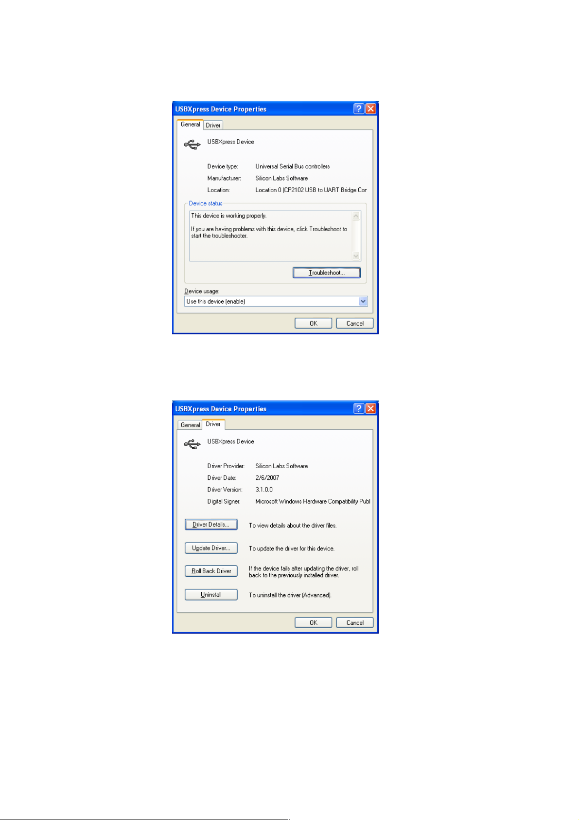
(1) Right click on the Fig. 13-3, and then click the [Properties].
(2) Click the [Driver] tab on the displayed screen.
Then, click the [Update Driver…].
Fig. 13-4
Fig. 13-5
-36-
Page 39

The [Hardware Update Wizard] is launched.
(3)
Select the【Install from a list or specific location(Advanced)】, and click the【Next】button to transit to the [Hardware
Update Wizard].
Fig. 13-6
(4) Select the【Don’t search. I will choose the driver to install.】, and then click the【Next】button.
Fig. 13-7
-37-
Page 40
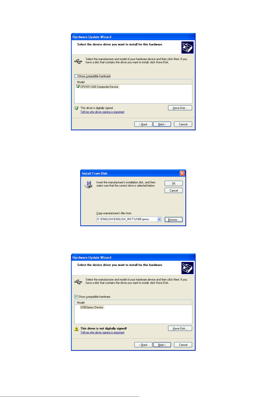
(5) Click
(6) Click[Browse…]button, and select
the【Have Disk…】button to install a device driver.
CD-ROM drive:\ENGLISH\ENGLISH_INST\USBExpress
in the install disk, and then click【OK】button.
Fig. 13-8
Fig. 13-9
(7) Select【USBXpress Device】that is listed in【Model】box, and click the【Next】button .
Fig. 13-10
-38-
Page 41

Now, installation starts. If the warning like the Fig. 13-12 concerning Windows Logo test appears during installation,
(8)
click【Co
ntinue Anyway】button.
Fig. 13-11
Fig. 13-12
(9) When installation has completed, the completion screen is displayed. Click【Finish】button. Now, restoration
procedure for USB communication error has completed.
Fig. 13-13
-39-
Page 42

13.1.3. Check after installation
Check【Universal Serial Bus controller】in the Device Manager.
Check if the device type has changed from Fig. 13-3[CP
check” to [USBXpress Device] that is highlighted in the Fig. 13-14 below.
2101 USB Composite Device]in the procedure “13.1.1. How to
Fig. 13-14
-40-
Page 43

 Loading...