

Page 1
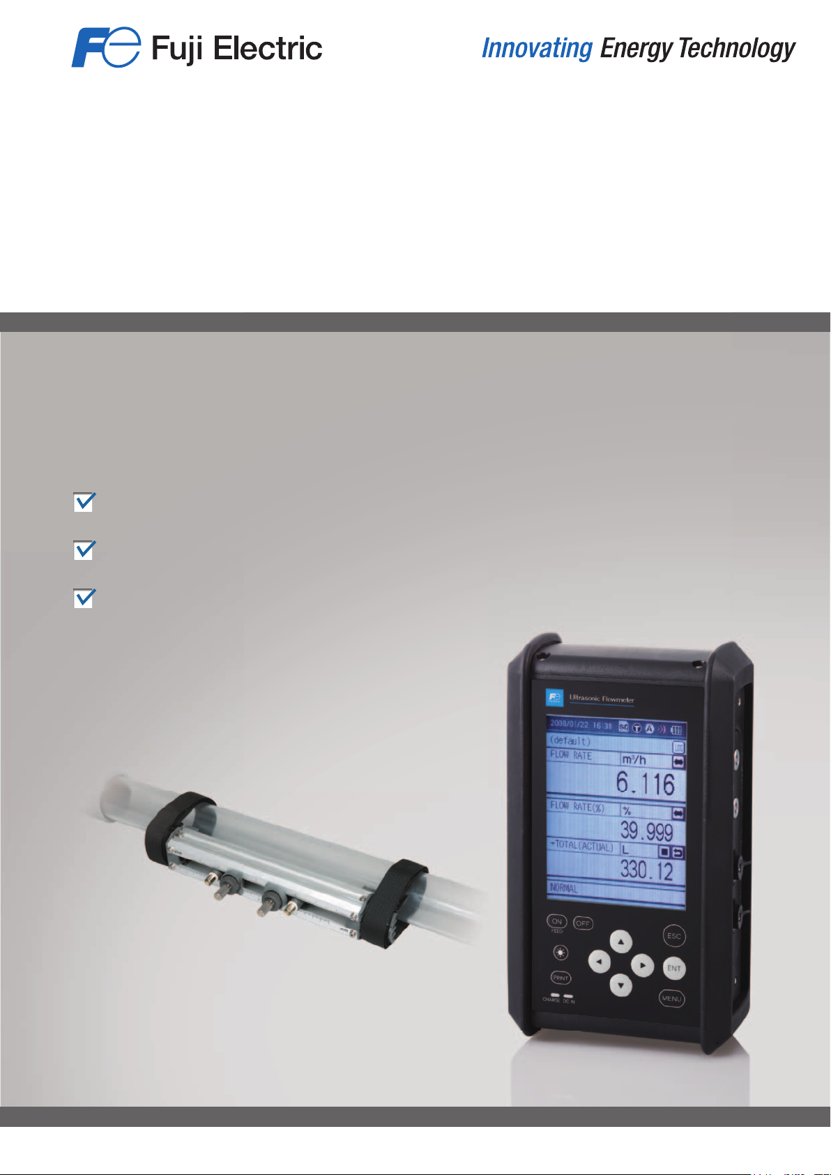
PORTABLE TYPE
ULTRASONIC FLOWMETER
Easy Measurement Anytime Anywhere
Compact and Lightweight—Only 1 kg
Easy-to-Install Detector
Consumed Energy Calculation
21A1-E-0009d
Page 2
Clamp-on Detector & Portable Transmitter
You can start measurement anytime you wish without interrupting the plant operation
15
16
17
18
1
2
4
3
7
6
5
8
27
10
9
11
28
12
13
29
14
20
30
24
25
26
19
22
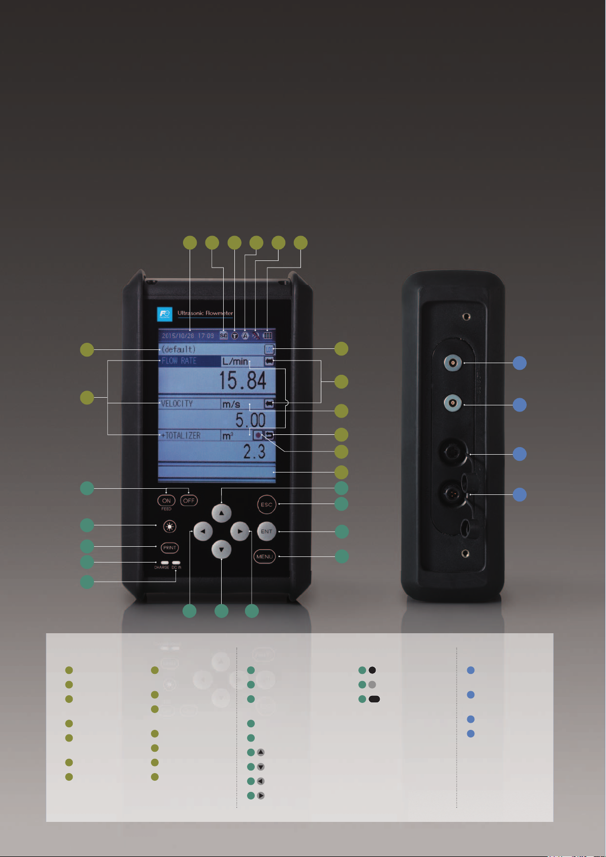
Display Operation keys Side
1
Date & time
2
SD memory card
3
Measurement
mode
4
AI/AO status
5
Ultrasonic signal
level indicator
6
Battery indicator
7
Site name
2
8
Quick logger start/
stop button
9
Kind of data
10
Switch to graph
view
11
Unit
12
Totalizer reset
13
Totalizer ON/OFF
14
Measurement
status
21
23
15
Power ON/OFF
16
Backlight ON/OFF
17
Print out or data-saving
on SD card
18
Charging status
19
Power supply
20
Up key
21
Down key
22
Left key
23
Right key
ESC
24
Escape key
ENT
25
Enter key
MENU
26
Menu key
Flow transmitter (FSC)
27
Downstream
sensor
28
Upstream
sensor
29
AI/AO
30
12 V DC power
Page 3
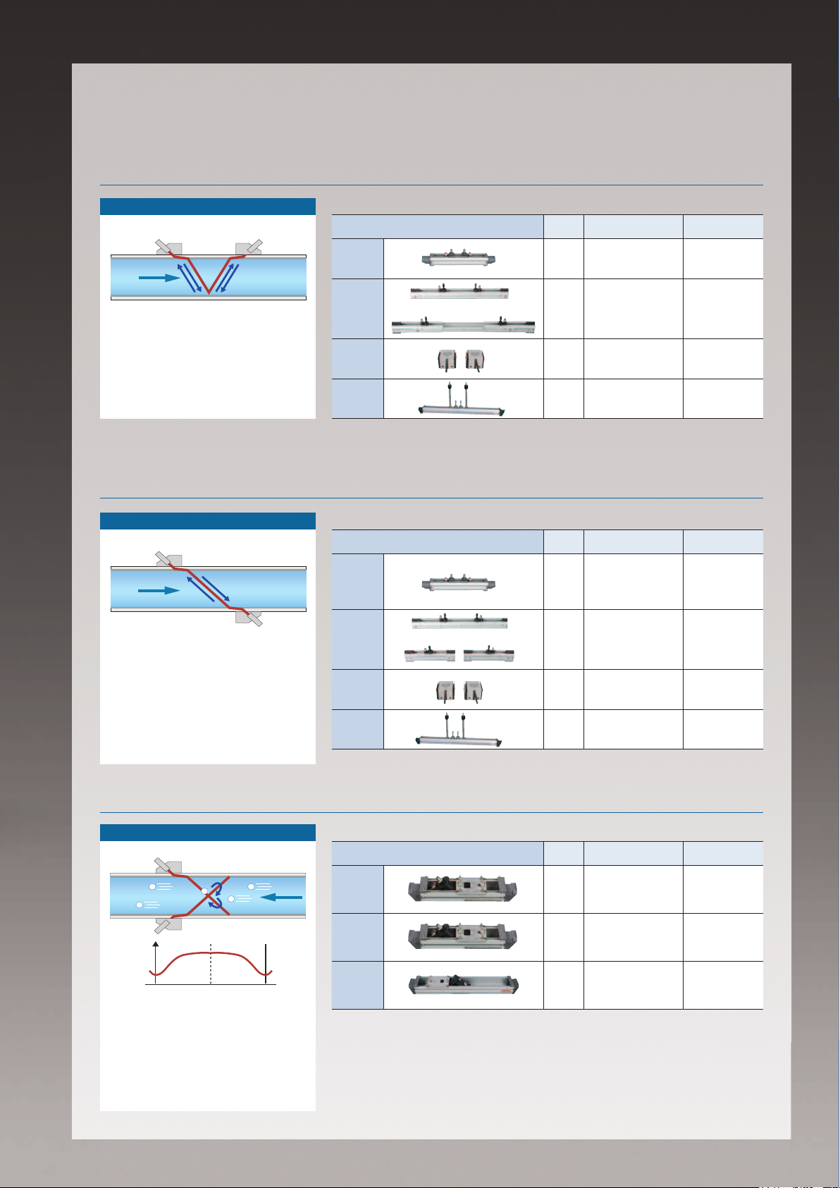
Select the best confi guration for your application
Sensor 1 Sensor 2
Flow
Sensor 1
Sensor 2
Flow
Sensor 1 Sensor 2
Flow
Transit time difference: V method
Principle
Sensor 1 Sensor 2
Flow
A pair of sensors aligned on the outside
wall of a pipe. The sensors emit ultrasonic pulse in turn, and detect the transit time difference of the pulse, by which
the fl ow rate is calculated.
Detectors
For small
diameter
pipes
Extendable rail
type
For large
pipes
For high
tempera-
ture
Transit time difference: Z method
Principle
Sensor 1
Flow
Detectors
For small
diameter
pipes
Appearance Model Pipe diameter (mm)
FSSD 13 to100 -40 to +100
Extended
↓
FSSC 50 to 600 -40 to +120
FSSE 200 to 3000 -40 to +80
FSSH 50 to 250 -40 to +200
Appearance Model Pipe diameter (mm)
FSSD 150 to 300 -40 to +100
Fluid tempera-
ture (ºC)
Fluid tempera-
ture (ºC)
A pair of sensors installed on the outside wall of a pipe, facing each other
slantingly. The sensors emit ultrasonic
pulse in turn, and detect the transit time
difference of the pulse. This method is
used mainly when the V method is not
available due to the space limitation, or
when the fl uid has high turbidity.
Pulse doppler method: for real-time fl ow pro le analysis
Sensor 1
Air bubbles
Sensor 2
velocity
The frequency of ultrasonic pulses refl ected by air bubbles or solid particles
changes according to the fl ow velocity.
The pulse doppler flowmeter uses this
frequency shift to determine the flow
velocity pro le.
Principle
Reflection
Sensor 2
Sensor 1Sensor 2Flow
CenterPipe wall Pipe wall
Flow
Extendable rail
type
For large
pipes
For high
tempera-
ture
Detectors
Small
Middle
Large
Separated
↓
FSSC 200 to 1200 -40 to +120
FSSE 200 to 6000 -40 to +80
FSSH 150 to 400 -40 to +200
Appearance Model Pipe diameter (mm)
FSDP2 40 to 200 -40 to +100
FSDP1 100 to 400 -40 to +80
FSDP0 200 to 1000 -40 to +80
Fluid tempera-
ture (ºC)
3
Page 4

Designed for Ease-of-Use
Easy Measurement Anytime Anywhere
Handy and battery-powered design allows you to take
measurement when and where needed.
Real-Time Monitoring of Flow Pro le
Using the ow transmitter FSC in combination with the
optional pulse doppler detector (FSD) enables realtime monitoring of ow pro le
(option).
Consumed Energy Calculation
A function to obtain thermal energies exchanged via
uid used in air-conditioning systems. The transmitter
calculates the consumed thermal energy based on the
forward ow temperature, the return ow temperature,
and the ow rate.
4–20 mA DC output (1 point)
Flow
Temperature sensor
T1: Forward flow temperature
Heat
source
Temperature sensor
Data Management on PC
transmitter
transmitter
Flow
Detector (FSS)
Q: flow rateT2: Return flow temperature
Data in SD card can be transmitted to your PC through
a USB cable.
Consumed thermal energy
q = K‧ Q‧(T1 -T2)
K: heat coefficient
(K for heating = 4.123)
Load
Flow pro le indication
Carrying Case
The dedicated case accommodates all the necessary
equipment including:
●
Flow transmitter
●
Detector (FSSC or FSSD)
●
Acoustic coupler (silicone grease)
●
Signal cable
●
Analog I/O cable
●
Strap parameter loader software)
●
AC power adapter
●
Power cable
●
Mounting belt
●
USB cable
●
CD-ROM (instruction manual,
Loader software provided
Parameter setting screen
Flow trend screen
Flow pro le screen
Carrying case
4
Page 5

Data Storage on SD Card
Easy-to-Mount Detector
The transmitter automatically saves the measured data
on SD memory card at user-specifi ed cycle. You can
also send the data through USB port to your PC.
For example, a 512 MB memory card can store the data of two
years' worth (at a data save cycles of 30 s, 14 kinds of data).
SD card up to 8 GB can be used.
Cover
USB port
SD memory card slot
Multilingual Display
Mounting detector requires no tools. You can start
measurement anytime.
On-Site Printing (option)
You can print out the measured data or screenshot by
the dedicated printer.
English
Chinese
Easy-to-See LCD
Received waveform
Logger data
12 Hours of Continuous Operation
with Built-in Battery
FSC can serve long hours of outdoor measurement.
Accessories for Comfortable Operation
(option)
· Hand strap
Helps you hold the transmitter
· Stand
Holds the transmitter at an easy-to-see angle
* The hand strap and the stand cannot be used simultaneously.
5
Page 6

Visualization of water use
Amount of water used
Applications
Reduction of Water Used in Plant Utilities
Visual depiction of a facility’s water use results in more effective
management of water consumption.
Measurement
in the right place
at the right time
Building C
Building B
Main pipe
1 2 3 4 5 6 7 8 9 10
Building A Building B Building C
(Day)
Spool piece
ultrasonic owmeter
Energy Consumption in Air-Conditioning Systems
Calculates the thermal energy received and sent with liquid in
air-conditioning system.
Flow transmitter
Temperature
sensor
TS: Forward flow temperature
Heat source Load
Temperature
sensor
Detector (FSS)
Q: flow rateTR: Return flow temperature
Building A
4–20 mA DC Analog Output (1 point)
Flow rate or
Consumed thermal energy
Serial Communication (USB port)
Cooling mode, heating mode, or heating/
cooling auto switching mode
Corrosive Fluid
Ultrasonic owmeters can take measurement on glass,
metallic, and plastic pipes.
Strong alkali
6
Strong acid
Wash Water in Food Manufacturing
Plants
Easier installation and lower maintenance compared to
mechanical owmeters or Coriolis owmeters
Food
processing
equipment
Wash water
Page 7

Ordering Code Select a code for each digit to congure the model for your application.
5 6 7 8 9 10 11
F S C S 3 - 0
Flow transmitter
Digit
Specications Code
Transmitter unit
5
Standard unit 1
Standard unit + printer 2
Flow velocity prole
6
None 0
With (A detector for ow velocity prole measurement is required)
AC power adapter + cable
125 V AC (Japan, North America) A
7
250 V AC (EU, Korea) B
250 V AC (China) C
Revision code 3
8
SD memory card
9
None 0
With (512 MB) 1
Instruction manual / default language setting
None / English Y
With / Japanese J
11
With / English E
With / Chinese C
Scope of Delivery
1. Transmitter unit
2. AC power adapter with AC/DC conversion cable
3. Power cable
4. Analog I/O cable (1.5 m)
5. USB cable (1 m)
6. Carrying case
Flow transmitter (FSC)
Transmit time
method ow
detector (FSS)
Pulse doppler
ow detector
(FSDP)
* Parameter loader software is available from our website at:
http://www.fujielectric.com/products/instruments/
7. Strap
8. Signal cable (5 m × 2)
9. CD-ROM (instruction manual, parameter loader
software)
Option (as specied by order)
1. SD memory card (512 MB)
2. Printer (with 1 roll of paper)
3. Instruction manual
1. Detector unit
2. Signal cable conversion cable (provided when the
detector is FSSE)
3. Mounting belt or wire (as specied by order)
4. Silicone grease or silicone-free grease (as speci-
ed by order)
1. Detector unit
2. Mounting belt or wire
3. Silicone grease (100 g)
4 5 6 7 8 9 10
F S S 1 -
Detector (transit time difference method)
Digit
Type
Extendable rail type
For small diameter pipes
4
For large pipes
For high temperature
1
Guide rail
5
Standard 1
Long (Selectable when the 4th code is D)
Mounting belt
None Y
Stainless belt (for pipe diameters ≤ 300 mm) A
Plastic cloth belt (for pipe diameters ≤ 300 mm) B
6
SS belt with screws (for pipe diameters ≤ 600 mm) C
Wire (for pipe diameters ≤ 1500 mm) D
Wire (for pipe diameters ≤ 6000 mm) E
Acoustic coupler
None Y
Silicone-free grease B
7
Silicone grease
Grease for high temperature (Selectable when the 4th code is H)
Revision code 1
8
Waterproof treatment
9
None Y
3
With*
(Selectable when the 4th code is C or E) B
Tag plate
10
None Y
Stainless steel tag plate (The tag number need to be specied.)
*1: Select an appropriate mounting belt in 6th code in reference to the following table.
Mounting method
V method A, B, or C C D
Z method C D D
Possible combination of 4th code and 6th code
Y
A
B
C
6th code
D
E
*2: Normally, select the silicone grease as an acoustic coupler. A silicone grease comes
in a 100 gram tube.
*3: Two 10-meter signal cables are included. Waterproof treatment makes the detector
submersible for ve days.
Detector
(pulse doppler method, for ow velocity prole measurement)
Model Specications
FSDP20Y1 Small (40 mm to 200 mm)
FSDP10Y1 Middle (100 mm to 400 mm)
FSDP00Y1 Large (200 mm to 1000 mm)
Specications Code
∅
50–1200 mm C
∅
13–100 mm D
∅
200–6000 mm E
∅
50–400 mm H
*1
*2
≤ 300 mm ≤ 600 mm ≤ 1200 mm
4th code
C D E H
✔ ✔ ✔ ✔
✔ ✔ ✔
✔ ✔
✔ ✔ ✔
✔ ✔
✔
3
C
D
A
7
Page 8

Specications
Fluid
Pipe inner
diameter
Fluid temperature
Velocity
Accuracy
Output cycle
Path
Display
Analog output
Analog input
Power supply
voltage
Transmitter
enclosure
Transmitter
dimensions
Transmitter
weight
SD card
Uniform liquid through which ultrasonic wave can
propagate (water, distilled water, alcohol, etc.)
13 mm to 6000 mm (depending on detector)
-40°C to +200°C (depending on detector)
0 to ±32 m/s (minimum ±0.3 m/s)
±1.0% of rate (depending on ow velocity)
1 s
1 path, transit time method
Color LCD with back light
4–20 mA DC (1 point)
4–20 mA DC / 1–5 V DC (2 points)
Built-in battery (12 hours of continuous operation)
IP64 (no printer version)
210 × 120 × 65 mm (no printer version)
Approx. 1 kg
512 MB (stores 2 years’ worth data)
Dimensions
Serial
communication
Functions
Options
Transmission data:
Data stored in SD card (instantaneous value, total
value, etc.)
Through USB port
Cable length: up to 3 m
Damping time constant (0 to 100 s)
Instantaneous value (10-digit) *The ow rate unit is
selectable
Total value (10-digit) *The ow rate unit is selectable
Consumed energy calculation
Self-diagnosis (battery power, received wave)
Flash memory (measurement parameters for pipe,
uid, sensor, etc)
Number of registration sites: 32
Zero point adjustment (by setting zero or clearing
zero)
Graph view, waveform view
Language (Japanese, English, Germain, French,
Spanish, Chinese)
Bidirectional ow measurement
Low ow cut-off (0–5 m/s)
Printer: screen hard copy, periodic printing and
logged data printing
Detector for ow velocity prole measurement:
displays ow velocity prole of instantaneous value
and average value
210±2.5
SD memory card slot
Flow transmitter (FSCS1) Flow transmitter with printer (FSCS2)
65±1.8
DOWNSTREAM
UPSTREAM
AI/AO
DC12V
SENSOR
120±1.8 65±1.8
DOWNSTREAM
UPSTREAM
AI/AO
DC12V
Power switch
USB port
USB
2-M4, Depth5 (both sides)
Sensor (downstream)
SENSOR
Sensor (upstream)
Analog input/output
DC power input
Approx. 320±4.5
SD memory card slot
120±1.8
Power switch
USB port
USB
Printer
2-M4, Depth5 (both sides)
Sensor (downstream)
Sensor (upstream)
Analog input/output
DC power input
Information in this catalog is subject to change without notice.
Read the instruction manuals thoroughly before using the products.
Instrumentation & Sensors Planning Dept.
1, Fuji-machi, Hino-city, Tokyo 191-8502, Japan
http://www.fujielectric.com
Phone: +81-42-514-8930 Fax: +81-42-583-8275
http://www.fujielectric.com/products/instruments/
Printed in Japan 2018-1/5 FOLS
 Loading...