

Page 1
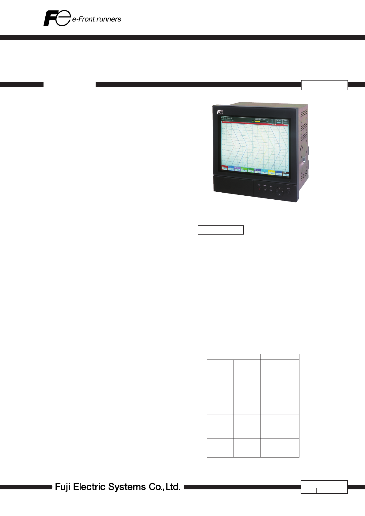
PAPERLESS RECORDER
DATA SHEET
OVERVIEW
This is a paperless recorder that displays measured data on
the LCD in real time and stores data in CompactFlash.
The type of input such as thermocouple, resistance bulb,
D.C. voltage (current), etc. can be arbitrarily set to 36 channels at the maximum.
The data stored in CompactFlash can be regenerated on the
screen, and the use of supplied support software allows the
data to be regenerated on a PC screen.
The data recorded in ASCII format can be directly read in a
spreadsheet such as Excel, which facilitates the processing on a PC. (The data recorded in binary format cannot
be read in.)
FEATURES
1. Large capacity storage by CompactFlash
Measured data is periodically stored in CompactFlash.
In case of 256 MB, for example, display fi les for about
one year and a half (display refresh cycle 30 sec) can
be taken up (in case of ASCII data format, 9 channels,
maximum/minimum recording).
2. Quick search and display of past data
Data stored in CompactFlash can be displayed in succession by scrolling the screen.
3. Various display capability
Depending on the object of measurement, the most
suitable display format can be selected from a variety of
formats including bar graph display, trend display, digital
display, etc.
4. PC support software supplied as standard
Loader software that enables easy display and change of
set data and data viewer software that regenerates the
data stored in CompactFlash are supplied as standard.
5. 36-point recording
12 types of thermocouples, 2 types of resistance bulbs
and DC voltage/current input can be recorded up to 36
points.
6. LCD extinguishing function
Automatically extinguishes the LCD if nothing is operated
for certain time. You can set the time after a lapse of
which the LCD is extinguished via parameter "LCD extinguishing time". The settable range is 0 to 60 minutes.
Setting at 0 minute overrides the function, whereby the
LCD will never extinguish.
This function prevents the backlight life from shortening
uselessly. During the extinguishment, the power consumption can be reduced.
7. Ethernet function (Option)
FTP, Web server, e-mail and MODBUS-TCP are available
using 10Base-T.
PHU
SPECIFICATIONS
Input system
Number of input points:
9, 18, 27 or 36 points (Can be selected
at the time of purchase)
Input circuit: Input mutual isolation (See ”Others” on
page 4 for the withstand voltage)
Resistance bulb measured current:
about. 1 mA
Measuring cycles:
9 or 18 points….100ms cycles
27 or 36 points….200ms cycles
Recording cycle: 1 second to 12 hours
Input types: Thermocouple, resistance bulb, DC
voltage, and DC current (Shunt resistors
are fi tted in input terminals).
Note) Provide a shunt resistor (type:
PHZP0101) separately.
Measuring range
Input types Reference range
Thermocouple B
Resistance bulb JPt100
DC voltage 50mV
Note) B, R, S, K, E, J, T, N : U : Cu-Cu · Ni (DIN 43710)
JIS C 1602, DIN IEC 584-1 PN: Platinel
W : 5%Re-26%Re · W JPt100 : JIS C 1604 (Hoskins Mfg. Co. USA) Pt100, Pt50 : JIS 1604, DIN IEC 751
L : Fe-Cu · Ni (DIN 43710)
R
S
K
E
J
T
N
W
L
U
PN
Pt100
Ni100
Pt50
Cu50
500mV
1-5 V
0-5V
400.0 to 1760.0°C
0.0 to 1760.0°C
0.0 to 1760.0°C
–200.0 to 1370.0°C
–200.0 to 800.0°C
–200.0 to 1100.0°C
–200.0 to 400.0°C
0.0 to 1300.0°C
0.0 to 1760.0°C
–200.0 to 900.0°C
–200.0 to 400.0°C
0.0 to 1300.0°C
–200.0 to 600.0°C
–200.0 to 600.0°C
–60.0 to 180.0°C
–200.0 to 600.0°C
–50.0 to 200.0°C
0.00 to 50.00mV
0.0 to 500.0mV
1.000 to 5.000V
0.000 to 5.000V
1989 (Old JIS Pt 100)
EDS10-79
May. 17, 2007Date
Page 2

PHU
Selection of input types:
By key operation on the front panel. Note
that the same input type (thermocouple,
resistance bulb, voltage) should be set every 2 channels. Refer to "Setting method
of input types" for details.
Burn-out function:
Provided as standard for thermocouple
and resistance bulb inputs. If the input
has been open-circuited, the recording
level swings over 100%.
Thermocouple burn-out current:
approx. 0.2 µA
Input fi lter function:
Settable for each channel (primary delay
fi lter)
Time constants are settable in the range
from 0 to 900 sec.
Scaling function: Possible by DC voltage (current) input
Scaling range: -32767 to 32767
Decimal position:
settable at any point
Unit symbol: Selectable out of 125 dif-
ferent units or 12 user
units of up to 7 characters.
Subtraction function:
Subtraction between each channel is
allowed.
Totalizing function:
The measured value of each channel
can be totalized. Applicable to daily,
monthly, annual or external input totalizing.
F value calculation function:
F value (extinction value of bacteria by
sterilization by heating) can be calculated from the measured temperature
by each channel.
Square rooter function:
Square rooter can be performed
against the input value per each channel.
Computation function:
The following calculation is available with
the computation function.
(1) Computation function:
Addition, subtraction, multiplication,
division, absolute value, exponential,
square-root extraction, LOG, LN, EXP,
humidity, maximum, minimum, average, and integration.
(2) Computation input enable:
Analog input (Ch1 to 72), integration
input (Ch1 to 72), DI (DI1 to 16), communication input (No.1 to 36), and
constant number (No.1 to 60).
Indication system
Indicator: 12” TFT color LCD (800 x 600 dots)
with backlight, no contrast adjustment.
On the LCD, certain picture elements
remain lit or extinguished. On account
of the nature inherent to LCD, the
brightness may be non-uniform. But,
such are not troubles.
Color of indication:
14 colors
Applicable language:
English, French (switchable)
Life of backlight: 50,000 hours in terms of total lighting
time.
(Replace the backlight as a set of display
unit. If the LCD extinguishing function is
resorted to, the LCD can be used longer
as much.)
Trend display: Direction: vertical and horizontal
Number of channels: 10, 6 or 4 channels
per screen group. (Input: 72 points at the
maximum).
Display refreshment cycles:
select from 1 second to 12 hours
Scale display or no-display can be se-
lected.
Bar graph display:
Number of channels: 10, 6 or 4 channels
per screen group. (Input: 72 points at the
maximum).
Display refreshment cycles: 1 second
Analog meter display:
Number of channels: 10, 6 or 4 channels
per screen group. Display in bar graphs
or in analog meters can be selected.
Display refresh cycle: 1 second
Digital display: Number of channels: 10, 6 or 4 chan-
nels per screen group. (Input: 72 points
at the maximum).
Display refreshment cycles: 1 second
Totalizing data display:
Number of channels: 10, 6 or 4 channels
per screen group. (Input: 72 points at the
maximum).
Display refresh cycle: 1 second
Event summary display:
Alarm summary and message summar y
can be displayed. The message occurrence information and message display
can be switched.
Ethernet log display:
E-mail sending, FTP server log in/off and
MODBUS TCP/IP communication start/
stop can be displayed.
Parameter display/set:
Already-set Data Display and Set Change
Display screen
TAG indication: Number of characters to be displayed:
Up to 8 characters
Up to 8 characters (Note 1) at 10 or 6
channel display.
Up to 16 characters at 4 channel display.
Note 1: Up to 7 characters only can be
displayed on certain screens.
Characters to be displayed:
Alphanumerics
Tag, unit and channel No. display:
Which can be displayed depends on the
particular screen. Refer to the table below.
(Keywords only are extracted.)
2
Page 3

Screen
Trend
Bar graph
Analog
meter
Instantaneous
value
{ : Displayed
¯ : 1 item only can be displayed
–
: Nothing can be displayed
Channnels per
screen
4 or less
5, 6
7 or more
6 or less
7 or more
Tag 1 Tag 2 Unit ch Np.
{
¯
{
Item
All
–
{
–
All
–
All
{
¯
¯
{
{
Historical trend display:
Displays past recording data read from
compact fl ash, currently recording data or
just recorded data. The recording chart can
be scrolled or, via time designation, the
control can jump to an arbitrary recording
chart.
Number of screen groups:
8 groups (Up to 10 channels per 1
group can be registered.)
Keyboard
No. of Keys: 8
Function: Use to select various screens and set
various parameters.
Recording function
External memory media:
Compact Flash card
Format according to FAT16 or FAT. Oth-
erwise, reading and saving are impossible.
Recording capacity:
512 MB maximum (compact fl ash). Limit-
ing the recording fi le to 64 MB is recommended (for 112 hours if display refresh
cycle is 1 second. See Table 1 (p. 6).)
If impossible, up to 256 MB is tolerated. A fi le recorded beyond could not
be opened.
* Only the Sandisk‘s compact fl ash is war-
ranted. And please change the compact
fl ash every six month to prevent the data
losing.
Recording method:
Turning ON the REC key allows measured
data to be written at fi xed cycles.
Recorded as a new fi le whenever the
recording starts.
Data save cycles:
Linked to the display refreshment cycles
on the ”Real Time Trend” screen. However, they are automatically set to about
1 minute if the refreshment cycles are
set to less than 1 minute.
Trend data: Measurement data sampled at mea-
surement cycle is saved in terms of
mean value, instantaneous value or
maximum/minimum value.
Event data: Saves alarm data and message data.
Further saves power ON and OFF, if any,
after starting recording.
Totalizing value data:
Totalizing value data at designat-
ed timing is recorded per channel.
Totalized value data at designated total-
ized value recording cycle or the sum total
is recorded in the totalizing fi le. You can
choose which type you want to record.
For each cahnnel. it can be select as
totalizing action from Analog input to-
talization, Digital input count or period
of Digital input ON, and it can be se-
lect as totalizing period type from Dairy,
Weekly, Monthly, Annual, Periodic,
Dairy (time set) or External input signal.
Even if a power failure occues during total-
ization and then the power is restored,the
totalization restarts from the value before
power failure.
Confi guration data:
Confi guration data can be saved. And this
data can also download to recorder.
Storage capacity :
Approximately 1.5 years when the display
refresh cycle is 30 seconds (in case of
9-channel recording in ASCII data format,
and 256 MB compact fl ash used). Refer
to Table 1.
Residual capacity of memory:
Indicates how much of the memory card
has been used on the screen. If the
residual capacity is none, the recording
stops.
Compact fl ash: Manufactured by SanDisk
URL: http://www.sandisk.com
Type: SDCFB-256 (256MB)
Available at any PC shops
Data format: Either of ASCII or binary format can be
selected. (Switching cannot be made
while the recording is in progress. In
the case of ASCII format, the data can
be directly read on Excel, etc. The data
recorded in binary format cannot be
read directly.)
Approximately 166 bytes per sampling
for maximum/minimum recording of
9-channel input in ASCII format, or
approximately 40 bytes for maximum/
minimum recording of 9-channel input
in binary format.
Alarm function
No. of settings: Up to 4 alarms for each channel are set-
table.
Type of alarm: High/Low limits
Indication: Status (alarm types) is displayed on
digital display unit when an alarm oc-
curs.
Historical display on alarm summary (Alarm
start/cancel time and alarm types)
Hysteresis: Set within the recording range of 0 to
100%
Acts on high or low limit alarm, and does
not affect the battery alarm nor memory
full alarm.
3
Page 4

PHU
Relay output: Number of points; 20 (option: Up to 2
cards with relay output can be mounted.)
Transistor output (open collector output):
16 points (option)
Alarm latch function:
Holds alarm indication and alarm output
even after measurement value has left
the alarm range.
ON/OFF operation is performed according
to key setting.
Power supply
Rated power voltage:
100 to 240V AC
Range of operating voltage:
90 to 264V AC
Supply frequency:
50/60Hz ±2% (both employable)
Power consumption
Power voltage
100V AC
240V AC
Consumption
About 65VA
About 80VA
Structure
Mounting method:
Panel-mounted (vertical panel)
Thickness of panel:
2 to 26 mm
Materials: Stainless steel for case, PC-ABS for
bezel
Color: Silver for case, Munsell N2.0 (black) for
bezel
External dimensions:
300 (W) × 300 (H) × 220.5 (D) mm
Mass: About 4.7 kg (9-point input, without op-
tion)
About 6.4 kg (full option)
External terminal board:
Input terminal: M3 screw terminal
Power terminal: M4 screw terminal
Operating condition
Power supply voltage:
90 to 264V AC
Power supply frequency:
50/60Hz ±2% (sharing)
Ambient temperature:
Without Ethernet function: 0 to 50°C*
With Ethernet function: 0 to 40°C*
Ambient humidity:
20 to 80%RH
Vibration: 10 to 60Hz 0.2m/s
2
or less
Shock: None
Magnetic fi eld: 400 A/m or less
Signal source resistance:
Thermocouple input .… 1kΩ or less
Resistance bulb input .… 10Ω/wire or less
(resistance of each wire of 3-wire system
should be balanced).
Voltage input .… 0.1% or less of input
resistance
1
2
Mounting posture:
Forward tilt 0, backward tilt within 30,
horizontal 0
Warm-up time: One hour or more after power ON
*1: In case of the 12th digit of ordering code is ”Y”.
*2: In case of the 12th digit of ordering code is ”E”.
Reference standard
Accuracy/resolution:
Measuring conditions (23±2˚C, 65±10%
RH, power voltage, frequency fl uctuation
within ±1%, no external noise, warm-up
time of 1 hour or more, vertical mounting, standard values of signal source
resistance and wiring resistance... within
1% )
Input types
Thermocouple
Resistance
bulb
DC voltage 50mV
Note 1) Digital indication accuracy is a percentage (%) with respect to
input range of 1 page.
Note 2) No error of reference contact compensation of thermocouple is
included.
B
R
S
K
E
J
T
N
W
L
U
PN
JPt100
Pt100
Pt50
Ni100
Cu50
500mV
5V
Digital indication
accuracy
±(0.15%+1 digit)
±(0.3%+1 digit)
for the range shown below
Thermocouple B :
400 to 600°C
Thermocouples R and S :
0 to 300°C
Thermocouples K, E, J, T,
L and U :
±(0.15%+1 digit)
±(0.5%+1 digit)
±(0.15%+1 digit)
Note 1
-
200 to -100°C
Digital indication
resolution
0.1°C
0.1°C
10V
100 V
1mV
Error of reference contact compensation:
K, E, J, T, N, L, U, PN: ±0.5˚C
R, S, B, W: ±1.0˚C
(when measured at 0˚C or more)
Max. input voltage:
Thermocouple, resistance bulb,
DC voltage: ±10V DC (continuous)
Input impedance: Thermocouple,
DC voltage: About 1MΩ
Others
Clock: With calendar function (Christian era)
Accuracy: ±50 ppm or less (monthly error:
about 2 minutes)
However, time error at power ON/OFF is
not included.
Memory backup: Parameters are saved to the internal
non-volatile fl ash memory.
The clock is backed up with built-in lithium
battery.
Trend data is not backed up.
4
Page 5

Insulation resistance:
100 MΩ (when measured between each
terminal and ground by using a 500V DC
megger)
Withstand voltage:
Input terminal – input terminal:
500 V AC, 1 min
Power terminal – ground:
2000V AC, 1 min
Input terminal – ground:500V AC, 1 min
Alarm terminal (contact output) –
ground: 2000 V AC, 1 min
Alarm terminal (contact output) – alarm
terminal (contact output):
750 V AC, 1 min
Communication terminal – ground:
500 V AC, 1 min
Alarm terminal (open collector) –
ground: 500 V AC, 1 min
Power terminal – input terminal:
500 V AC, 1 min
Effect on operation
Effect of power supply fl uctuation conditions:
For the fl uctuation in the range from 90
to 264V AC (frequeucy: 50/60Hz)
Reading change: ±(0.2%+1 digit) or
lower.
For the fl uctuation in the range from 47
to 63Hz (power voltage: 100V AC)
Reading change: ±(0.2%+1 digit) or
lower.
Effect of input signal resistance:
Thermocouple input: 50μV±1 digit per
100Ω
DC voltage: Fluctuation for resistance
value equivalent to 0.1% of the input
resistance: ±(0.2%+1 digit) or lower.
Reistance bulb (for wiring resistance of
10Ω for 1 line (the same for 3 lines))
Reading change: ±(0.2%+1 digit) or
lower.
Effect of ambient temperature:
Reading change: ±(0.3%+1 digit)/10˚C or
lower.
Effect of Mounting position:
For the backward 30˚ slant
Reading change: ±(0.2%+1 digit) or
lower.
Effect of vibration:
When sine wave of 10 to 60Hz with the
acceleration of 0.2m/s
2
is applied in each
direction for 2 hours.
Reading change: ±(0.2%+1 digit) or
lower.
Safety and EMC standard
Safety standard: Based on IEC61010-1
EMC standard: Based on EN61326
Transportation/storage conditions
Temperature: -10 to +60˚C
Humidity: 5 to 90%RH
Vibration: 10 to 60Hz, 2.45 m/s
Shock: 294m/s
2
or lower (packed state)
2
or lower
Additional function (option)
■ Alarm relay output (11th digit of code symbols: ”1”,
”2”, ”4” or ”5”)
Up to 2 cards with 10-point relay output can be
mounted. (Maximum 20 points)
Terminal structure:
M3 screw terminal
Alarm relay output:
1a contact output (10 points/card),
Individual channel or common output (OR
output) allowed.
Rating: Contact capacity 240V AC/3A,
30V DC/3A (Resistive load).
■ Alarm open collector output (11 digit of code symbols
is ”3”, ”4” or ”5”)
Card having 16 alarm points (open collector output)
can be mounted.
Terminal structure:
M3 screw terminal
Alarm output: Open-collector transistor output (16
points)
Rating: 30V DC/0.1A (resistance load)
■ DI input (7 digits of code symbol is ”1”)
Card having 16 DI input can be mounted.
Terminal structure:
M3 screw terminal
DI input: No-voltage contact input (16 points).
Contact input allows following controls.
(1) Recording start/stop
(2) Message set
(3) F value calculation reset
(4) Totalizing start/stop
(5) Totalized value reset
(6) LCD (backlight) lighting
(7) E-mail sending
Input pulse width:
ON pulse width: 400msec or more
OFF pulse width: 400msec or more
Ethernet (Option)
The following can be performed through the Ethernet
function.
■ HTTP server (Internet Explorer 6 is available)
Measurement display:
Digitally displays the measurement of
each channel of the recorder and alarm
occurrence status.
Event summary display:
Displays event summary including alarm
ON/OFF and issuance of messages.
Main unit information display:
Displays memory use conditions and
information on the main unit such as
the battery end warning.
Integrated value display:
Digitally displays the integrated value of
each channel of the recorder.
Note 1
5
Page 6

PHU
■ FTP server (Internet Explorer 6 available.)
Note 1
File download: Record fi les stored in compact fl ash
(CF) can be downloaded from the
browser.
File delete: Record fi les stored in CF can be deleted
from the browser.
Access authentication:
Authenticates access authority to FTP
server.
■ SMTP (e-mail client)
Transmits e-mails to specifi ed address
under the following conditions.
(1) When an alarm turns on or off
(2) When DI is set to ON or OFF
(3) When an error occurs to the main
unit (such as low battery or no
memory space)
(4) At specifi ed intervals
■ MODBUS TC/IP
Data read: Settings can be read through MODBUS
TCP/IP communication.
Data write: Settings can be written through MOD-
BUS TCP/IP communication.
Note1: Neither Netscape nor Mozilla Firefox
are available.
Support software
The following software is provided as standard.
• Applicable PC: PC/AT-compatible machine
• Operation on PC98-series machines by NEC is not guar-
anteed.
• Operation on self-made or shop-brand PCs is not guaran-
teed.
■ Loader software for PC
Major function: Performs various parameter setting/
change of the main unit
O/S: Windows 2000/XP (Windows Vista is
not supported.)
Required memory:
64MB or larger
Disk drive: Windows 2000/XP-capable CD-ROM
Hard disk capacity:
Free capacity of 30MB or larger re-
quired
Printer: Windows 2000/XP-capable printer and
printer driver
Note) PC loader communication cable (type PHZP1801) is
separately required.
■ Data viewer software
Major function: Regenerates the past trend record on
the PC from the data in the compact
fl ash. Provided with historical trend
display and event display functions.
Data can be changed to CSV fi le.
O/S: Windows 2000/XP (Windows Vista is
not supported.)
Required memory:
64MB or larger
Disk drive: Windows 2000/XP-capable CD-ROM
drive
Hard disk drive: Free capacity of 30MB or larger re-
quired
Printer: Windows 2000/XP-capable printer and
printer driver
Standard functions
Function
Record range
voluntary setting
Input type setting
Skip function
Trend display
TAG name display
Screen name
display
Unit creation
Scaling function
PV shift
Input filter
Burnout function
Historical
trend display
Recording range can be set by channel.
Input type can be set by channel.
(Key operation on the front face)
Set the same input type for every 2 channels.
Skips arbitrary channel display/recording.
Time display: Time is displayed at the top of the
Alarm display: On occurrence of an alarm and the
The compact flash usage is displayed with a
bargraph at the top.
By channel, Maximum of 8 characters.
Displays the screen name (maximum of 16
characters).
Industrial units can be arbitrarily created, Maximum
of 7 digits, 12 types.
Arbitrary scaling is allowed in the case of DC
voltage input. Decimal point position can also be
arbitrarily set in the range from -32767 to 32767.
Shift the zero point and slant of the reading.
Prevents sudden fluctuation of input for each
channel (primary delay filter).
Time constant: 0 to 900 seconds.
Displays the break of thermocouple/resistance bulb
input by scaling out to 100% side.
Regenerates and displays the data stored in the
compact flash by scrolling the screen.
Displays data of a designated time.
Description
trend display screen.
restoration, alarm is displayed in the
alarm display field.
Table 1. Recording capacity
The recording can be made for the period of time listed
in the tables shown below under the following conditions.
• 9 input points
• Recording data format: ASCII
• Recording type: Maximum/minimum recording
• No alarm, nor message, nor other events.
CompactFlash size 64MB
Display upgrade cycle
Recordable capacity
(about)
CompactFlash size 256MB
Display upgrade cycle
Recordable capacity(about) 18 days 187 days 1.5 years 3 years
• When the number of input points goes on increasing, the
period becomes as follows.
18 input points; The period is approximately one half of
27 input points; The period is approximately one-third
36 input points; The period is approximately one-fourth
• In binary format, the period is approximately 4 times as
long as those listed in the table.
• For recording type of mean or instantaneous value, the
number of days is approximately 2 times as long.
1 sec 10 sec 30 sec 1 min 10 min
112 hours
46 days 140 days 280 days 7.7 years
1 sec 10 sec 30 sec 1 min
those listed in the table.
of those listed in the table.
of those listed in the table.
6
Page 7
When compact fl ash is not used, up to 6M bytes of
the recording data and the event data can be stored
in the main unit. (In case of 32-channel in Max./Min.
recording, approximately 400,000 data can be stored.
For 11 hours at the display refresh cycle of 1 second.
The number of the save data varies depending on the
number of the event data.
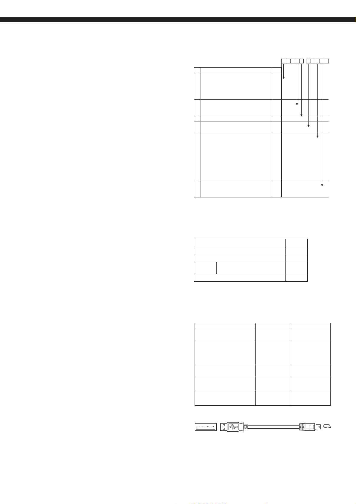
CODE SYMBOLS
Digit
<Number of input points>
4
9 points
18 points
27 points
36 points
<DI input>
7
Without
With (16 points)
<Modification No.(fixed)>
8
<Display (instruction manual)>
9
English
<Alarm output>
11
Without
10 relay points
20 relay points
Transistor (open collector) 16 points
10 relay points + transistor
(open collector) 16 points
20 relay points + transistor
(open collector) 16 points
<Ethernet>
12
Without
With
Specifications
PHU
Note
45678
1
2
3
4
-
001
0
1
1
9 10111213
1Y
E
0
1
2
3
4
5
Y
E
SCOPE OF DELIVIRY
Item Quantity
Recorder
Panel mounting bracket
CD-ROM PC support software instruction
manual
Noise filter for the power supply 1
1
1
1
OPTIONAL ITEMS
Item Code Specification
Shunt resistor for DC
current input
PC loader communication
cable
CD-ROM with instruction
manual and support software
PC card adapter PHZP0501 For compact flash
Manufactured by SanDisk
Compact flash PHZP1301-256 256MB
Manufactured by SanDisk
* Shape of this cable is shown below
USB (A) male – USB (Mini-B ) male
PHZP0101 107p 0.1%
PHZP1801 Length 3m with
connector
USB-A/USB miniB
terminal *
PHZP2501
B
7
Page 8

PHU
OUTLINE DIAGRAMS (Unit : mm)
PANEL MOUNTING TYPE
In the case of 9-point input
300
PUSH
In the case of 18-point input
300
Panel
300
Panel
26
t
2 ≤ t ≤ 26
26
220.5
175
Mounting bracket
220.5
175
Alarm output
transistor terminal
Alarm output
relay terminal
DO4
DO6
DO5
DO3
DO1 DO2
DO3
DO5
DO4DO2
DO1
DO13DO11DO12 DO14
DO22
VPD DO21
DO23
VPD
DO29
DO30
-+
+
CH1
CH2
TC?^V
TC?^V
3
1 2
4
6
5 11-8-109
+
+
-
-
CH6
CH7
TC?^V
TC?^V
LOWER
1716
‰º’i
18 2724 25-26
19 20
DO14DO11 DO12 DO13
DO31
+
21
DO15
DO24
CH1-CH9
TC?^V
7
DO15
DO25
DO32
DO6
DO16
DO33 PCD
CH3
RCJ
Rcj
R-MODULE
280
DO1-10
?iRY?j
DO11-20
?iRY?j
DO21-36
?iTr?j
Input terminal (1 to 9 points)
Alarm output
transistor terminal
Alarm output
relay terminal
Ethernet terminal
(option)
DO10
DO8 DO9DO7
DO9DO8DO7
DO10
DO18 DO19DO17DO16
DO20
DO19 DO20DO18DO17
DO27 DO28DO26
PCD
DO35DO34
DO36
+
+
CH4
TC?^V
12
-
+
TC?^V
22 23
0V
LAN
Communicator
CH5
TC?^V
UPPER
15
ã’i
13 14
+
CH9CH8
TC?^V
280
318
Ethernet terminal
(option)
DI input terminal
Power terminal
100-240VAC?`
L
N
DIDI
DI2
DI8
DI6
DI5
DI3
DI1
DI7
DI4
0V
DI
DI
DI15
DI11
DI10
DI16DI14
DI13
DI9
DI12
0V
0V
DI1-16
DI input terminal
Power terminal
100-240VAC?`
DO4
DO10
DO6
DO5
DO3
DO1 DO2
DO8 DO9DO7
DO3
DO5
DO4DO2
DO1
DO9DO8DO7
DO6
DO13DO11DO12 DO14
DO18 DO19DO17DO16
DO15
DO15
DO14DO11 DO12 DO13
DO16
DO22
VPD DO21
DO23
DO25
DO24
DO27 DO28DO26
VPD
DO29
DO30
DO33 PCD
DO32
DO31
DO35DO34
CH1-CH9
+
+
+
CH2
CH3
TC?^V
TC?^V
TC?^V
3
4
6
7
5 11-8-109
+
-
-
+
CH7
RCJ
CH6
TC?^V
TC?^V
18 2724 25-26
21
19 20
22 23
Rcj
R-MODULE
DO10
DO20
DO19 DO20DO18DO17
PCD
DO36
LAN
Communicator
-
+
-
+ +
CH4
CH5
TC?^V
TC?^V
UPPER
12
15
ã’i
13 14
2928
+
++
CH9CH8
TC?^V
TC?^V
LOWER
43-44
‰º’i
280
318
DO1-10
?iRY?j
DO11-20
?iRY?j
DO21-36
300
PUSH
280
?iTr?j
-+
CH1
TC?^V
1 2
+
-
TC?^V
LOWER
1716
‰º’i
t
2 ≤ t ≤ 26
Mounting bracket
Input terminal
(1 to 9 points)
L
N
DIDI
DI4
DI2
DI8
DI6
DI5
DI3
DI1
DI7
0V
0V
DI
DI
DI9
DI12
DI15
DI11
DI10
DI16DI14
DI13
0V
0V
DI1-16
CH10-CH18
+-
+ -
CH10
TC?^V
30
CH15
CH11
33
CH16 RCJ
TC?^V
CH12
TC?^V
TC?^V
34-3231
373635
+
48-4645 47 49-50 54-535251
Rcj
R-MODULE
CH13
38 39
TC?^V TC?^V
-
+
CH14
TC?^V
UPPER
ã’i
42
4140
+
CH18
CH17
Input terminal
(10 to 18 points)
8
Page 9
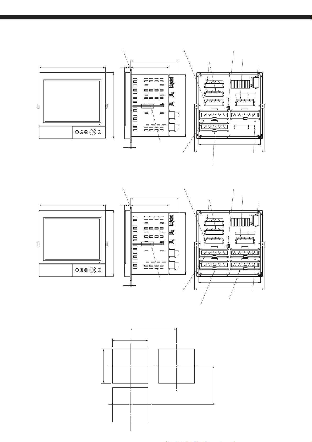
In the case of 27-point input
300
PUSH
In the case of 36-point input
300
Panel
300
Panel
26
t
2 ≤ t ≤ 26
26
Alarm output transistor terminal
220.5
175
280
Mounting bracket
Input terminal
(1 to 9 points)
Alarm output transistor terminal
220.5
175
Ethernet terminal (option)
Alarm output
relay terminal
DO4
DO10
DO6
DO5
DO3
DO1 DO2
DO8 DO9DO7
DO3
DO5
DO4DO2
DO1
DO9DO8DO7
DO6
DO1-10
?iRY?j
DO11-20
?iRY?j
DO21-36
?iTr?j
-+
CH1
TC?^V
1 2
+
-
TC?^V
LOWER
1716
‰º’i
-
+
CH10
TC?^V
29
28
+
TC?^V
LOWER
43-44
‰º’i
DO10
DO15
DO20
DO13DO11DO12 DO14
DO18 DO19DO17DO16
DO15
DO14DO11 DO12 D O13
DO16
DO19 DO20DO18DO17
DO22
VPD DO21
DO23
PCD
DO25
DO24
DO27 DO28DO26
VPD
DO29
DO30
DO36
DO33 PCD
DO32
DO31
DO35DO34
CH1-CH9
+
+
+
+
CH2
CH3
CH4
TC?^V
TC?^V
TC?^V
TC?^V
3
4
12
13 14
6
7
5 11-8-109
+
+
-
-
+
CH7
RCJ
CH6
TC?^V
TC?^V
18
21
19 20
22 23
Rcj
R-MODULE
CH19-CH27
+
-
+
-
+
+
CH11
CH12
CH13
TC?^V
TC?^V
TC?^V
30
CH15
45
TC?^V
33
34
31
38
35-37
36
-32+
-
+
CH16
CH17
RCJ
TC?^V
TC?^V
48
46
47
493950
51
Rcj
R-MODULE
-
TC?^V
-
41+40
TC?^V
CH5
UPPER
15
CH14
UPPER
42
CH18
5352
ã’i
CH9CH8
2724 25-26
ã’i
54
280
318
0V
LAN
Communicator
+ +
+ -
CH10
TC?^V
2928
30
++
CH15
TC?^V
LOWER
43-44
‰º’i
DI1
DI
0V
TC?^V
DI input terminal
Power terminal
100-240VAC?`
L
N
DIDI
DI4
DI2
DI8
DI6
DI5
DI3
DI7
0V
DI
DI9
DI12
DI15
DI11
DI10
DI16DI14
DI13
0V
CH10-CH18
+
+-
CH11
CH13
CH12
TC?^V
TC?^V
33
34-3231
38 39
373635
+
CH16 RCJ
CH17
TC?^V TC?^V
TC?^V
48-4645 47 49-50 54-535251
Rcj
R-MODULE
Input terminal
(10 to 18 points)
Input terminal (19 to 27 points)
Ethernet terminal (option)
Alarm output
relay terminal
DI input terminal
Power terminal
DI1-16
CH14
TC?^V
UPPER
ã’i
42
4140
+
CH18
PUSH
PANEL CUTOUT SIZE
100-240VAC?`
L
N
DIDI
DI4
DI2
DI8
DI6
DI5
DI3
DI1
DI7
0V
0V
DI
DI12
DI15
DI9
DI11
DI10
DI16DI14
DI13
0V
CH10-CH18
+ -
-
+-
CH10
CH11
CH13
CH12
TC?^V
TC?^V
TC?^V
2928
33
34-3231
30
38 39
373635
+
CH16 RCJ
CH15
CH17
TC?^V TC?^V
TC?^V
48-4645 47
49-50 54-535251
Rcj
R-MODULE
CH28-CH36
-83+
+
+
-
-
+
-
CH28
CH29
CH31
CH30
TC?^V
TC?^V
TC?^V
88
87
84 85+86
93
92
91
89
90
-
-
-
+
CH34
CH33
CH35
RCJ
TC?^V
TC?^V
98
102
100
99
101
104
103
Rcj
Input terminal
(10 to 18 points)
DI
0V
DI1-16
-
+
CH14
TC?^V
UPPER
ã’i
42
4140
+
CH18
+
CH32
TC?^V
UPPER
96
ã’i
94
95
+
CH36
TC?^V
108
107
105
106
300
t
2 ≤ t ≤ 26
Mounting bracket
Input terminal
(1 to 9 points)
280
DO4
DO10
DO6
DO5
DO3
DO1 DO2
DO8 DO9DO7
DO3
DO5
DO4DO2
DO1
DO9DO8DO7
DO6
DO1-10
?iRY?j
DO11-20
?iRY?j
DO21-36
?iTr?j
-+
CH1
TC?^V
1 2
+
-
TC?^V
LOWER
1716
‰º’i
-
+
CH10
TC?^V
29
28
+
TC?^V
LOWER
43-44
‰º’i
DO10
DO13DO11DO12 DO14
DO18 DO19DO17DO16
DO15
DO20
DO19 DO20DO18DO17
DO15
DO14DO11 DO12 D O13
DO16
DO22
VPD DO21
DO23
PCD
DO25
DO24
DO27 DO28DO26
VPD
DO29
DO30
DO36
DO33 PCD
DO32
DO31
DO35DO34
CH1-CH9
+
+
-
+
+
CH5
CH2
CH3
CH4
TC?^V
TC?^V
TC?^V
TC?^V
3
4
12
13 14
6
7
5 11-8-109
+
+
-
-
+
CH7
RCJ
CH6
18
+
30
CH15
45
TC?^V
TC?^V
TC?^V
21
19 20
22 23
Rcj
R-MODULE
CH19-CH27
+
-
-
+
+
-
CH13
CH14
CH11
CH12
TC?^V
TC?^V
TC?^V
TC?^V
33
34
31
38
35-37
36
41+40
-32+
-
+
-
CH16
CH17
RCJ
TC?^V
TC?^V
TC?^V
48
46
47
493950
51
5352
Rcj
R-MODULER-MODULE
UPPER
15
ã’i
CH9CH8
2724 25-26
UPPER
ã’i
42
CH18
54
LAN
Communicator
+ +
TC?^V
++
TC?^V
LOWER
43-44
‰º’i
TC?^V
82
+
TC?^V
LOWER
97
‰º’i
280
318
Input terminal (28 to 36 points)
Input terminal (19 to 27 points)
360 MIN
+2
0
281
0
+2
281
320 MIN
9
Page 10

PHU
EXTERNAL CONNECTION DIAGRAMS
Alarm output relay terminal
M3 screw
DO1
DO2
DO3
DO4
DO5
DO6
DO7
DO8
DO9
1
2
3
4
5
6
7
8
11
12
13
14
15
16
17
DO10
9
10
18
19
Power terminal
20
M4 screw
DO11
DO12
21
22
31
VPD
DO21
41
42
24V DC+
DO29 DO30 DO31 DO32 DO33 DO34 DO35 DO36 0V
51
Voltage
Thermocouple
Resistance
Resistance
Thermocouple
Alarm output relay terminal
100 to 240V AC
50/60Hz
M3 screw
DO13
DO14
DO15
DO16
DO17
DO18
DO19
23
24
25
26
27
32
33
34
35
36
Alarm output transistor terminal
M3 screw
DO22
DO23
DO24
DO25
43
44
45
52
53
54
DO26
46
47
55
56
28
37
DO27
48
57
29
38
DO28
49
58
DO20
30
39
PCD
50
59
40
DI input terminal
M3 screw
DI 0V
DI1
DI2
DI3
DI4
61
62
63
DI9 DI10 DI11 DI12 DI13 DI14 DI15 DI16
60
71
64
72
73
DI5
65
66
74
75
Input terminal
Number of input points = 1 to 9 points Number of input points = 10 to 18 points
CH1 CH2 CH3 CH4 CH5
++--++--++--++--++-
-
M3 screw
Voltage
Thermocouple
CH10 CH11 CH12 CH13 CH14
++--++--++--++--++-
Resistance
bulb
6789221023112412251326142715
16117218319420521
bulb
33 34 35 36493750385139524053415442
4328442945304631473248
Resistance
bulb
++--++-
RCJ
++--++-
Thermocouple
bulb
++--++-
RCJ
DI6
DI7
67
68
76
77
++--++-
DI8
DI 0V
69
70
78
79
80
-
10
Voltage
Voltage
Thermocouple
Resistance
bulb
Resistance
bulb
Thermocouple
Voltage
Voltage
CH15 CH16
-
CH17 CH18
-
CH6 CH7
-
CH8 CH9
-
Number of input points = 19 to 27 points Number of input points = 28 to 36 points
CH19 CH20 CH21 CH22 CH23
++--++--++--++--++-
Voltage
-
Thermocouple
CH28 CH29 CH30 CH31 CH32
++--++--++--++--++-
-
Resistance
bulb
60 61 62 63766477657866796780688169
7055715672577358745975
9782988399841008510186102
87 88 89 90
1039110492105931069410795108
Resistance
bulb
Voltage
++--++-
CH33 CH34
RCJ
++--++-
-
CH35 CH36
-
++--++-
CH24 CH25
RCJ
++--++-
-
CH26 CH27
-
Thermocouple
Note) For current input, connect an optional shunt resistance to a voltage input terminal.
96
Page 11

SELECTING INPUT TYPE
The input type is the same every 2 channels.
The input type of channel 2, 4, 6, 8, 11, 13, 15, 17, 20, 22, 24, 26, 29, 31, 33 and 35 can only be set in the same category
of previous channel.
Note, however, that input type can be arbitrarily selected only for channels 9, 18, 27 and 36 irrespective of the type
allocated to other channels.
The following input types are available.
DetailsInput type
Thermocouple, 50mV
Resistance bulb
500mV
5V
Example of channel input type selection (for 18 points input)
Channel 1 K thermocouple Thermocouple,
Channel 2 T thermocouple
Channel 3 1-5V 5V
Channel 4 0-5V
Channel 5
Channel 6
Channel 7
Channel 8
Channel 9
Channel 10
Channel 11
Channel 12
Channel 13
Channel 14
Channel 15
Channel 16
Channel 17
Channel 18
J thermocouple
K thermocouple
Other channels
K, E, J, T, R, S, B, N, W, L, U, and PN thermocouples, 50mV
Pt100, JPt100, Ni100, Pt50 and Cu50
500mV
1 to 5V, 0 to 5V
Input type DescriptionInput type
The type of thermocouple can be arbitrarily selected
50mV
Pt100 Resistance bulb The type of resistance bulb can be arbitrarily selected
JPt100
500mV 500mV
500mV
Thermocouple, 50mV
Thermocouple,
50mV
Skip
1-5 V
Pt100
Skip
500mV
50mV
5V Skip and other channel can arbitrarily be selected
Resistance bulb
500mV
Thermocouple, 50mV
for each channel.
for each channel.
Input type can be arbitrarily selected for channel 9.
The input type of the thermocouple and 50mV is the
same.
irrespective of the input type.
Input type can be arbitrarily selected for channel 18.50mV
Note 1) Windows2000/XP, Excel, and Internet Explorer are the trademarks or registered trademarks of Microsoft Corpora-
tion in the U.S.
Note 2) CompactFlash is the trademark or registered trademark of Sandisk Corporation.
Note 3) Modbus is the trademark or registered trademark of AEG Schneider Automation International.
Note 4) The PC98 Series are the trademark or registered trademark of NEC Corporation.
Note 5) Netscape is the trademark or registered trademark of Netscape Communications Corp.
Note 6) Firefox is the trade mark of Mozilla Corporation.
11
Page 12

PHU
Caution on Safety
*Before using this product, be sure to read its instruction manual in advance.
Head Office
Gate City Ohsaki, East Tower, 11-2, Osaki 1-chome,
Shinagawa-ku, Tokyo 141-0032, Japan
http://www.fesys.co.jp/eng
Instrumentation Div.
International Sales Dept.
No.1, Fuji-machi, Hino-city, Tokyo, 191-8502 Japan
Phone: 81-42-585-6201, 6202 Fax: 81-42-585-6187
http://www.fic-net.jp/eng
Information in this catalog is subject to change without notice.
Printed in Japan
 Loading...