

Page 1
Quick Reference
Sales Div. III, International Sales Group
Global Business Group
Gate City Ohsaki, East Tower, 11-2, Osaki 1-chome,
PAPERLESS RECORDER
Type : PHL
Shinagawa-ku, Tokyo 141-0032, Japan
http://www.fesys.co.jp/eng
http://www.fic-net.jp/eng
Phone: 81-42-585-6201, 6202 Fax: 81-42-585-6187
INP-TN2PHLQRb-E
Thank you for your purchasing Fuji Paperless Recorder (Type: PHL).
• Read this instruction manual carefully to ensure correct installation, operation and preparation. Incorrect handling may lead to accident or injury.
• Specifi cations of this unit is subject to change without prior notice for improvement.
• Modifi cation of this unit without permission is strictly prohibited.
Fuji will not be bear any responsibility for a trouble caused by such a modifi cation.
• This instruction manual should be kept by the person who is actually using the unit.
• After reading the manual, be sure to keep it at a place easy to access.
• This instruction manual should be delivered to the end user without fail.
Manufacturer : Fuji Electric Instrumentation Co., Ltd.
Type : Shown on nameplate of Recorder
Date of manufacture : Shown on nameplate of Recorder
Product nationality : Japan
CONTENTS
Specifi cations and Accessories ...................................... 1
Related Information ........................................................ 1
Caution on Safety (Please read fi rst) .............................. 2
For Proper Usage ........................................................... 5
1. Installation ................................................................ 5
2. Wiring....................................................................... 6
3. Operation Parts and Their Functions ....................... 7
Specifi cations and
Accessories
Before using the product, confi rm that it matches the
type ordered.
(For model code, please refer to page 12.)
Confi rm that all of the following accessories are
included.
Product name
(1)
Panel-mounting bracket
CD-ROM PC support software instruction manual
(2)
(3)
Panel packing for front face
(4)
Power supply noise filter
(5)
Quick reference (this manual)
(both in Japanese and English)
Quantity
Panel-mounted
2
1
1
1
1
Note: Windows is a registered trademark of Microsoft Corporation.
Modbus is a registered trademark of AEG Schneider Auto-
mation International.
Other product names are registered trademarks or trade-
marks of each manufacturer.
4. Display and Operation Procedure ............................ 8
5. List of Parameters .................................................... 9
6. Troubleshooting ....................................................... 11
7. Specifi cations ........................................................... 11
8. Code Symbols ......................................................... 12
9. Maintenance ............................................................ 12
Related Information
Refer to the following reference materials for details
about the items described in this manual.
Content Document
Specifications
Operation
Method
Communication
Function
Parameter
Loader
(software)
Data Viewer
(software)
Paperless Recorder (type: PHL)
Communication Functions Instruction
Manual (RS485 Modbus/Ethernet) for
Parameter Loader Instruction Manual for
Data Viewer Instruction Manual for
Catalogue
Instruction Manual for
Paperless Recorder
Paperless Recorder
Paperless Recorder
Reference
Number
ECNO: 1013
INP-TN2PHL-E
INP-TN513979-E
INP-TN513995-E
INP-TN514013-E
– 1 –
Page 2
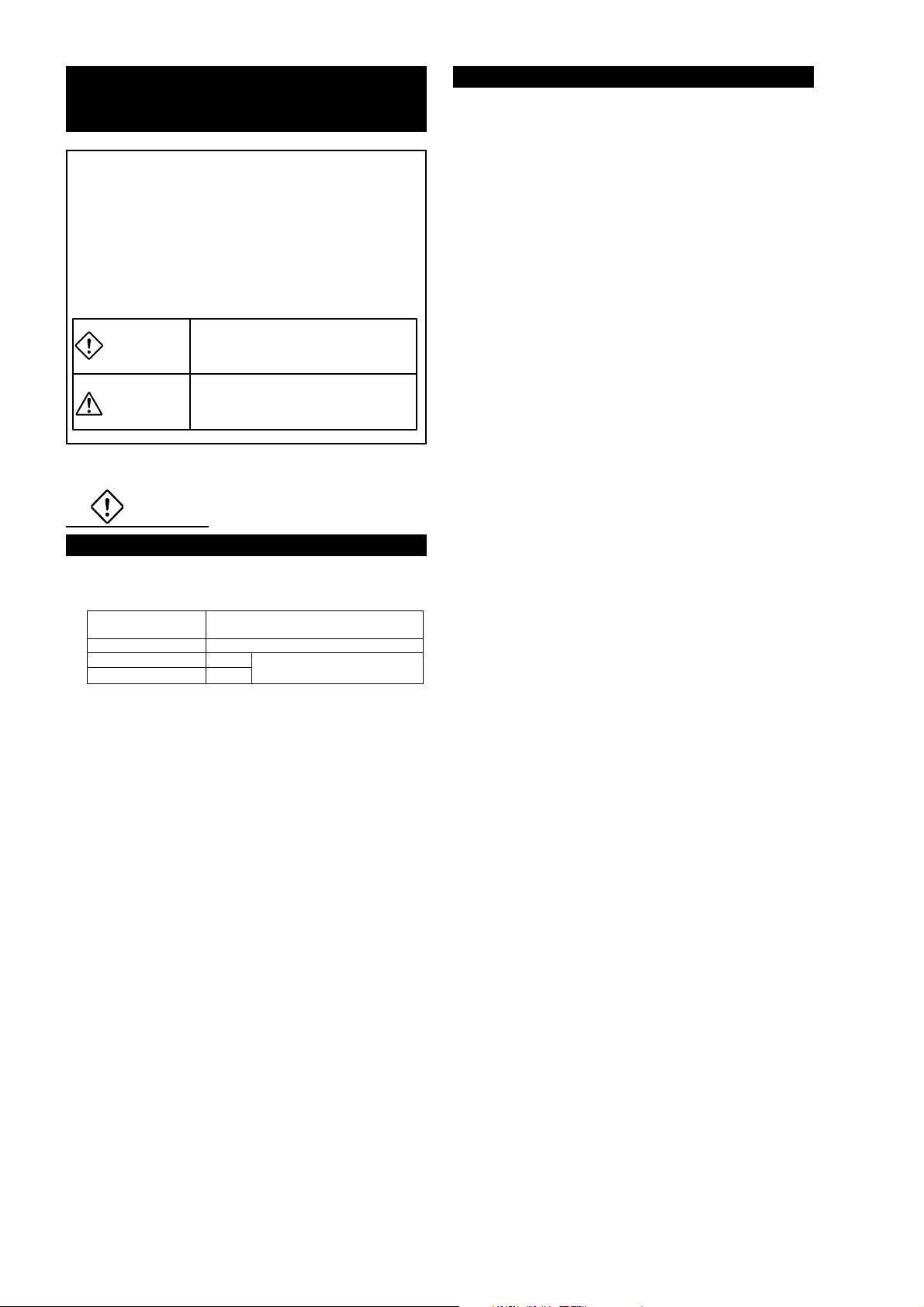
Caution on Safety
(Please read fi rst)
Read this “Caution on Safety” carefully before
using the instrument.
• Be sure to observe the instructions shown below,
because they describe important information on
safety. The degree of danger is classifi ed into the
following two levels: “DANGER” and “CAUTION.”
The signs and their meanings are as follows:
Improper handling may cause
DANGER
CAUTION
1. DANGER
dangerous situations that may
result in death or severe injury.
Improper handling may cause dangerous situations that may result in moderate or light injuries or property damage.
1.2 Maintenance
• Turn off the power before attaching/detaching the
module/unit. Otherwise electric shock, malfunction
or failure may result.
• We recommend you to perform periodic maintenance for the safe and continuous use of this instrument, because consumable parts or those which
deteriorate with time are mounted in this instrument.
• Do not block the ventilation holes at the top and the
bottom of this instrument. Otherwise a failure, malfunction, shortened service life, or fi re may result.
1.1 Installation
• This equipment is intended to be used under the
following conditions.
Ambient temperature 0 to 50°C (Without Ethernet function)
Ambient humidity 20 to 80% RH (with no condensation)
Installation category II
Pollution degree 2
• IP : 50 (Front) / 20 (Terminal)
• When there is a possibility that the abnormality of
this instrument may cause a major accident or damage to other instruments, externally install an adequate emergency stop circuit or a protection circuit
to prevent accidents.
• This product is provided with a built-in fuse that
cannot be replaced by the customer. Therefore, we
recommend you to separately provide adequate
fuses externally. (Rating: 250V, 2A)
The details of the built-in fuse are as follows.
Type : TR-5 19372, 3.15A (Manufactured by
Rating : 250V, 3.15A, Type: T (Slow-blow type)
• Feed the power-supply voltage to specifi cations to
prevent damages to and breakdown of the instrument.
• Never turn on the power before all the mounting and
wiring work are fi nished to prevent electric shock,
malfunction or failure of the instrument.
• Never use this instrument in an environment where
fl ammable or explosive gases exist, since this is not
of intrinsically safe construction.
• Never disassemble, remodel, modify, or repair this
instrument. Otherwise malfunction, electric shock,
or failure may result.
• Never touch the terminal while the instrument is being energized. Otherwise electric shock or malfunction may result.
0 to 40°C (With Ethernet function)
by IEC1010-1
Wickmann-Werke GmbH)
– 2 –
Page 3

2. Caution
2.1 Cautions when installing
• Never use the instrument if it is found damaged or
deformed when unpacked. Otherwise a fire, malfunction, or failure may result.
• Check that the instrument is to the proper specifi cations. Otherwise damage or failure may result.
• Do not give a shock to the instrument by falling or
toppling it. Otherwise damage or failure may result.
•
Avoid installing the instrument in the following places.
•
A place where the ambient temperature goes beyond the range from 0 to 50°C (0 to 40°C when
the instrument is mounted with its side face closely contacted, or provided with Ethernet function)
• A place where the ambient humidity goes beyond
the range from 20 to 80% RH
• A place where condensation occurs
• A place where corrosive gases (sulfuric gases or
ammonia, etc., in particular) or fl ammable gases
exist
• A place where vibration or impact may be applied
to the instrument (permissible continuous vibration condition: 4.9 m/s
• A place subjected to water, oil, chemicals, vapor,
or steam
• A place subjected to dust and high in salt or iron
content
• A place where inductive interference may have a
great effect, thus causing static electricity, magnetism, or noises
• A place subjected to heat accumulation by radi-
ant heat or the like
• A place that is affected by electromagnetic wave
from wireless machine or portable telephones.
• If the instrument is installed near other electronics
instruments, such as TV in particular, noises may
be caused. Take the following measures in these
cases.
• Place the instrument as far from the TV or the ra-
dio as possible (1m or more)
• Change the orientation of the antenna of the TV
or the radio.
• Use separate receptacles.
2.2 Cautions when installing to the panel
• When mounting this instrument against the panel,
pay attention not to apply stress to the case. Otherwise the case may be damaged.
• Fix the instrument by fastening the screws at the top
and the bottom of the supplied mounting bracket.
• The panel to be used should be more than 2 mm
thick.
• Excessive torque will cause damage to front panel
frame or result in case deformation.
Tightening torque: 0.2 N·m
• If the panel front is subject to water splashes, use
panel packing between the unit and panel.
2
or lower)
• Mount the unit horizontally, with
no tilt to the left or right (The
forward tilt should be 0° but the
unit may be inclined 0 to 30°
rearwards).
∠α
∠α = 60 to 90°
2.3 Cautions for wiring connection
• Only authorized workers should perform wiring.
Improper wiring may cause fi re, failure, or electric
shock.
• Be sure to ground the instrument. Otherwise electric shock or malfunction may result.
• When cables are connected to terminals of the recorder unit, don’t apply pulling force to them excessively. Excessive force to the terminal may result in
damage to the terminal or cable.
• Use the power cable that has the performance
equivalent to or higher than 600-V vinyl insulated
power cable (JIS C3307). Install the attached noise
fi lter within approximately 20cm from the power terminal of this instrument. (Wind the power cable 1 to
2 turns. The internal diameter of the ferrite core is
8mm.) Do not connect two or more instruments in
parallel.
• Up to 2 solderless terminals should be used when
connecting cables to terminals. Be sure to use an
insulation cap.
(Note)
1) At the completion of wiring of the input terminals, be sure to close the rear cover to ensure
the compensation of reference contact when
thermocouple input is used.
In case of thermocouple input, follow the steps
to stabilize temperature at the terminal.
• Be sure to attach input terminal cover.
• Don’t use a thick cable to prevent the effect
of radiation. The cable with a diameter of 0.5
mm or less is recommended.
• Don’t mount other instruments near a fan to
keep temperature stable.
2) For connection of lead wires to terminals, use
of sleeve-insulated clamping terminals (for M3
screw) is recommended.
3) This unit has no power fuse which is removable. Mount a power fuse outside the unit as
needed.
Recommended fuse rating: 250V AC, 1A
4) Don’t loosen screws that are secured to the
terminal case and power terminal.
• Input signal cables should be wired separately as
far as possible (30 cm or more) from power lines
and high-voltage lines to minimize the effect of inductive noise. Shielded cables should preferably
be used. In this case, the shield braids should be
earthed at one point.
• If a large noise is generated from the power supply,
provide an isolating transformer and use a noise fi lter.
• Install the instrument paying attention to prevent
foreign matters such as scraps, electric wire chips,
and iron powder from entering in the instrument.
– 3 –
Page 4

• Do not use the wires other than the specifi ed compensation conducting wires for the thermocouple
input connection. Otherwise improper indication or
malfunction may result.
• Use a wiring cable with low resistance and with
small resistance difference among the three wires
for the resistance bulb input connection. Otherwise
improper indication or malfunction may result.
2.4 Cautions in Operation
• Check every six months that the terminal screws
and mounting screws are securely fastened. Loose
screws may cause fi re or malfunction.
• When changing the setting during the operation or
forcibly outputting, starting or stopping the instrument, be sure to check that safety is ensured. Improper operation may result in damage or failure of
the instrument.
• Be sure to keep the attached terminal cover mounted on the terminal block during the operation. Otherwise electric shock or fi re may result.
• Stop using the instrument if it is immersed in water.
Otherwise electric leak, electric shock, or fi re may
result.
• Never use organic solvents such as alcohol or benzene when cleaning this instrument. Do not directly
water the main unit. Otherwise deterioration, failure, electric leak, electric shock, or fi re may result.
When cleaning the main unit, wipe with a dry cloth.
• Dispose the instrument as an industrial waste.
4) We recommend you to back up the data contained in the card once a month. If the CF card
is broken, the important log data contained in CF
card will be lost. Be sure to back up the data.
Before using a compact fl ash card adaptor, check
the capacity of the adaptor. If the capacity of the
memory card to be formatted is larger than that
of the adaptor, do not format the card. If the card
is formatted, a display may appear on Windows
indicating that formatting is completed, but PHL
does not recognize the completion of formatting.
5) Compact fl ash in the capacity range from 8MB to
1GB can be used.
6) The data recorded in the compact fl ash can be
regenerated on the PC by using the data viewer
(contained in the attached CD-ROM).
If the data is recorded in ASCII format, it can be
directly opened in a spreadsheet such as EXCEL.
However, large-amount data cannot be opened
(about 10MB or larger in the case of 9-point input,
and about 5MB or larger in the case of 18-point
input).
In those cases, read in data with the data viewer
(contained in the attached CD-ROM), and perform CSV conversion to divide the fi le, which allows the data to be read in.
The data recorded in binary format cannot be di-
rectly opened in a spreadsheet such as EXCEL.
Be careful not to make the size of a fi le too large
even if a large-capacity CF card is used. (Keep it
to 10MB or less.)
2.5 Handling memory card (Compact Flash)
• For the memory card, use Sandisk’s compact fl ash
memory (URL: http://www.sandisk.com). A compact
fl ash manufactured by other companies may not be
used or cause other problems.
1) Be sure to format the memory card with the PC
you use.
Format it as FAT16 or FAT. If it is formatted as
NTFS, for example, it cannot be used because
the PHL does not recognize it.
2) The memory card should be inserted in the prop-
er direction and fi xed securely to the slot.
3) Don’t turn OFF the power or remove the card
from the slot while data is being written in or read
from the card, or recorded data may be damaged
or lost.
– 4 –
Page 5

For Proper Usage
1 Installation
<Reference Item>
Model Designation Confirmation
1
2
3
Display and Operation Methods
4
5
Installation
Wiring
Turn Power On
Usage (Read before using)
List of parameters
Operation
<Details>
• Please confirm that the model
delivered matches your order.
• Dimensions
• Panel cutout
• How to install on the panel
• Terminal connection diagram
• How to handle the memory
card
• How to change the data
display screen
• How to change the parameter
setting screen
• Setting of parameters
• Stopping and starting the
recording
Dimensions/Panel Cutout
Dimensions
2≤ T ≤26
Pane l
144
160 140
Panel cutout
Mounting 1 unit Mounting n units
+1.5
137
0
+1.5
0
137
+1.5
21.6
0
137
(unit : mm)
(160 × n–22)
Mounting bracket
185
+2
0
T
24.6 when panel packing is used
161
136.5
When the display does not make sense.
6
• Displays during abnormalities.
Since about 60 minutes is needed until the unit becomes
thermally stable, wait for 60 minutes or more after turning the
power on before making measurements, etc.
Note1) If other instruments are placed under the recorder unit,
provide a space of 100 mm or more from the instrument or floor.
Note2) When unit is mounted with its side face closely contacted,
don’t use the packing.
Cautions on wiring
• Use crimped terminals matched to the screw size.
Tightening torque should be about 0.2 N·m.
• Do not connect anything to terminals not used.
AC power source
Protective grounding
Power ON
Power OFF
Double insulation
Electric shock hazard
– 5 –
Page 6

2 Wiring
Power supply terminal
(3)
Grounding terminal
(4)
L
N
100 240VAC
Screwed (panel mounted)
100 to 240V AC
50/60Hz
Alarm output (DO)/DI input terminal
211
161
162
163
171
172
173
181
182
183
191
192
193
DI1
212
DI2
213
DI3
214
DI4
215
DI5
216
DO1
217
DO2
218
DO3
219
DO4
220
DO5
221
DO6
222
DO7
223
DO8
224
DO9
225
DO10
Resistance
bulb
111
112
113
121
122
123
131
132
133
141
142
143
151
152
153
Thermocouple
+–+
+–+
+–+
+–+
+–+
Voltage
–
–
–
–
–
CH10
CH11
CH12
CH13
CH14
231
232
233
234
235
236
237
238
239
240
241
242
243
244
245
(1)
18 points Input terminal
Thermocouple
Voltage
CH15
CH16
CH17
CH18
Note) For current input, connect optional shunt resitors to the
voltage input terminals.
+
–
+
–
+
–
+
–
Resistance
bulb
+
–
+
–
RCJ
+
–
+
–
(1) Input terminal : Connect signal cable for each channel.
(2) Alarm (DO)/DI (External control unit):
Connect the output of alarm signals and the input of DI (external control) signals.
(for alarm [DO] 1 to 10 and DI [external control] 1 to 5)
(3) Power terminal : Connect power cable to L/N terminals. Power source to be connected should be free from noise.
(4) Grounding terminal : Connect to “G” terminal (Class-D, 100Ω or less).
(5) Communication, alarm (open collector) output and DI terminal:
Connect the input of alarm output (DO11) and DI (external control: D16) signals.
Connect communication signal cable to TRX (+) and TRX (-).
(6) Alarm (open collector) output and DI input:
Connect the input of alarm output (DO12 to 28) and DI (external control: DI7 to 10) signals.
(7) Ethernet terminal
Input terminal
Resistance
bulb
+
–
+
–
RCJ
+
–
+
–
DIO-CN
61
62
63
71
72
73
81
82
83
91
92
93
Rcj
R-MODULE
Fuji Electric
(1)(2)
Thermocouple
Voltage
+
–
CH6
+
–
CH7
+
–
CH8
+
–
CH9
Note) For current input, connect optional shunt resitors to the
voltage input terminals.
Thermocouple
Resistance
bulb
11
12
13
21
22
23
31
32
33
41
42
43
51
52
53
DIO
(+24V)
DIO
(0V)
DI6
SHLD DO11
TRX1 TRX2
+–+
+–+
+–+
+–+
+–+
Voltage
–
–
–
–
–
CH1
CH2
CH3
CH4
CH5
(7) Ethernet
RJ45 connector
(5)
Communication,
Alarm (open collector)
output, and DI terminal
VPD
DIO(+24V)
PCD
DIO(0V)
DO11
PCD
(6)
Alarm (open collector)
DI6
SHLD
TRX2
TRX1
output, and DI terminal
(D-Sub 25-pin)
1
14
13
25
DO12
6
7 DO13
8 DO14
9 DO15
10 DO16
11 DO17
12 DO18
15 DO19
16 DO20
17 DO21
18 DO22
19 DO23
20 DO24
21 DO25
22 DO26
23 DO27
24 DO28
2DI7
PCD
3DI8
4DI9
5 DI10
–
+
VPD
PCD
(Shield)
(
(+)
-
)
VPD
PCD
24VDC
MODBUS
communication
– 6 –
Page 7

3 Operation Parts and their Functions
(1)
(5)
(2)
OWER
(3)
S4
S3S2S1
S5
(6)
(4)
Name Function Name Function
)
S1 REC key
S2 DISP key
S3 SEL key
S4 Cursor key
S5 ENT key
• Used to start or stop recording.
Pressing once starts recording, and pressing once
again stops recording.
• U
sed to switch displayed contents. Every time it is
pressed, the display is switched in the following
order: (1) (2) (3) (4) (5) (6) (7) and back
to (1).
(1) Real time trend display
(2) Key guidance display
(3) Bar graph/analog meter display
(4) Digital display.
(5) Totalizing data display
(6) Event summary display
(7) Ethernet log display
• Used to switch the parameter setting screen to
the data display screen.
• Used to switch from the data display screen to the
parameter setting screen.
• Pressing the key on the parameter setting screen
switches to the screen one step up.
Note, however, that pressing the key on the menu
screen does not change screens.
(1) Used to select setting items.
(2) Used to increase or decrease numerical values.
(3) Pressing the key on the real time trend
displays the historical trend screen (*1).
At this time, the window can be scrolled using
the cursor key.
(4) Pressing the or the key on the real time
trend display, bar graph/analog meter display,
digital display, or totalized value display screen
switches group screens as follows.
key: Group 1 2 3 4 1 ...
key: Group ... 1 4 3 2 1
(1) Used for selection on the setting screen or
registration of the set data.
(2) If the key is pressed while the scales are
displayed on the real time trend display screen,
historical trend display screen (*1), or recorded
data display screen, the channels for which
scales are to be displayed can be switched.
(Scale of ch1 scale of ch2 ….. scale
of ch9 scale of ch1 scale of ch2…..)
(1) Display unit
(2) Power switch Used to turn the power ON or OFF.
(3) Memory card slot
(4) Memory card
ejection button
(5) Connector to
parameter loader
(6) Status indicator
lamp
(7) Memory card
Allows the Real time trend screen, Bar Graph
Display screen, Analog Meter Display screen,
Digital Display screen, Totalized Value Display
screen, Historical trend screen and other various
Parameter Set screens to be displayed.
Used for inserting the memory card.
Insert the card straight into the slot as shown in
upper right figure.
Be careful not to forcibly press the card if it is
inserted obliquely. Otherwise the pin on the PHL
may be damaged.
To remove the memory card from the slot,
press this button.
When changing parameters by using a loader,
connect the exclusive cable (optional cable: Type;
PHZP1801 or USB cable [USB (A) plug – USB
(mini B) plug] to the connector.
Displays power ON/OFF, LCD (screen) ON/OFF ,
and recording status.
Lamp ON (lighting)
: Power: ON,
LCD: ON (
Lamp blinking
(ON for 2 seconds / OFF for 2 seconds)
: Power: ON,
LCD: OFF (recording in progress)
Lamp blinking
(ON for 1 second / OFF for 1 second)
: Power: ON,
LCD: OFF (recording suspended)
Lamp OFF (extinction)
: Power : OF F
For the memory card, use Sandisk’s compact flash
memory (URL: http://www.sandisk.com). Other
memory cards may case trouble to the recorder.
recording in progress or suspended
Caution
1. Do not remove the memory card during recording. Refer to the
another Manual in the CD-ROM “Removing memory card
(compact flash)” for the removal of the memory card while
recording is in progress.
2. After inserting the memory card into the slot, don’t remove the
card until the recorder can acknowledge it.
3. Be careful with static electricity when removing the
Caution
ON
OFF
o
*1: The screen in the past of the data
currently recorded
*1: The screen in the past of the data
currently recorded
(7)
– 7 –
Page 8

4 Display and Operation Procedure
Data display screens
Real time
trend
(Group1)
(Group2)
(Group3)
(Group4)
Key
operation
guide
Historical
trend
(Group2)
Go to Real time trend, group1.
(Group3)
(Group4)
Bar gragh
or
Analog meter
(Group2)
(Group3)
(Group4)
Digital
display
(Group2)
(Group3)
(Group4)
Go to Parameter setting screen.
Totalizing
data
(Group2)
(Group3)
(Group4)
Event
summary
Ethernet
log
(To real time trend group1)
Parameter setting
Menu screen
Each parameter screen
(Example: channel 1 setting screen)
Input type :
Tag 1 :
Range start :
(1) Enter characters
Select characters using the
keys, and then move
to ENTRY . After that, press the
key to confirm the setting.
If press the , the setting is
canceled.
(2) Select or set the data
Select the item using the keys
or set the numeric character using
the keys. And then press
the key to confirm the data.
If press the , the setting is
canceled.
– 8 –
Page 9

5 List of Parameters
Parameter name
Basic setting
Channel setting
Math channel
setting
Setting at delivery (Default value) Setting range Remarks
Display refresh cycle : 1 second
Display compression : 1/1 1/1, 1/10, 1/30, 1/60
Alarm hysteresis : 0.2%
Alarm latch : OFF
LCD lights out time : 0
DO output at memory FULL: None
DO output at battery END: None
File division cycle : No division
File overwrite : OFF OFF, ON
Date format : yyyy/mm/dd
Select language : English English, French
MODBUS station No. : 1
MODBUS communication baud rate: 19200
MODBUS parity bit : Odd
Front communication : ON
Record data format : ASCII
Time setting :
Register data :
Input type: K-Type TC
(K thermocouple)
TAG1 : TAG½½ (½½: channel No.)
TAG2 : Blank
Unit : °C
Input range (range start/end): 0 to 1200
Decimal point position :
Input filter : 3 seconds
Subtraction channel : None
PV shift : 0.0
PV gain : 100%
F value calculation function: OFF
Display color: depends on channel No.
Recording type:
Maximum/minimum value recording
Recording mode : With record
Totalize setting
Totalize tag: STAG ½½ (½½: channel No.)
Totalize calculation : OFF
Totalize type : Periodic
Digital input : DI1 Digital input, Channel alarm
Totalize base time : /h /s, /min, /h, /day
Reset operation : ON OFF, ON
Totalize unit :
Totalize cut value : 0.0°C
Totalize scaling value
Totalize reset input : None None, Digital input, Channel alarm
Alarm setting
Alarm No. 1 type : OFF
Set point : 0.0°C
DO relay No. : None
From alarm No. 2 to No. 4
There are the same items above.
Formula setting: All formula are blank Calculation: +,
Tag1: TAG
TAG2 : Blank
½½ (½½
½½½½.½
: 1
: channel No.)
1 second to 12 hours
From 0.00 to 100.00%
OFF, ON
0 to 60 minutes
*1
None, DO1 to DO28
None, DO1 to DO28
No division, 1 hour, 1 day, 1 week, 1 month
yyyy/mm/dd, dd/mm/yyyy, dd-mmm-yy,
mm/dd/yyyy, mmm-dd-yy
0 to 255
9600, 19200 bps
None, Odd, Even
OFF, ON
ASCII, Binary
Skip, K, E, J, T, R, S, B, N, W, L, U,
PN thermocouple, Pt100, JPt100, Ni100, Cu50,
Pt50, 50mV, 500mV, 1-5V and 0-5V range
Up to 8 characters
Up to 8 characters
°
C, °F, Engineering unit in case of voltage input
Engineering value
0 to 900 seconds (In increments of 1 second)
0 to 30 (No subtraction at 0)
Engineering value –3276.7 to 3276.7
0.00 to 327.67%
OFF, ON
14 colors
Instantaneous value recording, average value
recording, maximum/minimum value recording
With record/Display only
Up to 8 characters
OFF, ON
Periodic, Daily, Weekly, Monthly, Annual,
Daily (Time set), External
Can be arbitrarily selected
Engineering value
1 to 32767
OFF, H, L
Engineering value
DO1 to DO28
-,½
, /
Function: ABS, POW, SQR, LOG, LN, EXP, RH,
MAX, MIN, H-P, L-P, AVG, SUM
Input: Input channel, Totalizer input, Digital input,
Communication input, Constant, Temporay data
Up to 8 characters
Up to 8 characters
*1
LCD keeps
turning on when
set “0”.
Set the same
input type for
every 2 channels.
– 9 –
Page 10

Parameter name
Math channel
setting
Math timer setting
Display screen
setting
Display setting
F value calculation
setting
Totalize setting
Message setting
Original unit definition
DI setting
Constant setting
Ethernet setting IP address : 0.0.0.0 0 to 255
E-mail setting SMTP IP address : 0.0.0.0 0 to 255
E-mail trigger
setting
User account
setting
Config and
record password
Setting at delivery (Default value) Setting range Remarks
Unit : °C Engineering unit
Measuring range (range start/end)
0.0 to 500.0
Decimal point position :
Engineering range (range start/end)
0.0 to 500.0
Square rooter : OFF
Input range (range start/end): 0 to 1200
Input filter : 3 seconds 0 to 900 seconds (In increments of 1 second)
Subtract channel : None 0 to 30
PV shift : 0.0 Engineering value
PV gain : 100.00% 0.00 to 327.67%
H-P, L-P timer cycle : 1 min
AVG timer cycle : 1 min
SUM timer cycle : 1 min
Trend back color : White
Historical back color : Black
Display configuration:
No. 1 to 9 = ch1 to 9
Decimal point position :
Manual reset : OFF
Totalize base time : 00:00
Totalize cycle : 1 hour
Weekly base day : Sunday
Monthly base day : 1 1 to 31
Start time, Stop time: 00:00 to 00:00 00:00 to 23:59
External input : DI1 Digital input, Channel alarm
Message : Blank
Unit : Blank
DI function: Function invalid
Constant : 0
Subnet mask : 0.0.0.0 0 to 255
Default gateway : 0.0.0.0 0 to 255
FTP server function : OFF, ON
FTP access control : OFF, ON
Web server function : OFF, ON
E-mail function : OFF, ON
MODBUS TCP/IP : OFF, ON
Sender’s mail
Add : Blank
Name : Blank Up to 32 characters
Receiver’s mail
Add1 to Add8 : Blank
Trigger timing : None None, DI ON, DI OFF,
Alarm Channel : 1 Channel 1 to 30
Alarm No. : 1 1 to 4
Title : Blank Up to 32 characters
Text1, 2 : Blank Up to 32 characters
PV value affixation : OFF, ON
Receiver’s add No. : 1 1 to 8
Mail send test :
User name : Blank Up to 16 characters
Password : Blank Up to 8 characters
User Level :
Security mode : Password Password, Logon
Password : 0000 0000 to 9999
Record Password : 0000 0000 to 9999
½½½½½.½ ½½½½½½, ½½½½½.½, ½½½½.½½, ½½½.½½½, ½½.½½½½
½½½½½.½ ½½½½½½, ½½½½½.½, ½½½½.½½, ½½½.½½½, ½½.½½½½
Administrator
Engineering value
Engineering value
OFF, ON
OFF, ONLogarithmic display : OFF
Engineering value
1 to 32767min
1 to 32767min
1 to 32767min
White, Black
White, Black
No.1 to 10, Each provided with ch1 to 30
OFF, ON
00:00 to 23:59
10, 20, 30 minutes, 1, 2, 3, 4, 6, 12 and 24 hours
Sunday to Saturday
Up to 32 characters
Up to 7 characters
Function invalid, Rec start/Rec stop, F value
calc. reset, Totalize start/stop, Totalize reset,
LCD ON
-
32767 to 32767
Up to 64 characters
Up to 64 characters
Alarm ON, Alarm OFF, Warning, Timer cycle
Administrator, Engineer, Operator, Guest
– 10 –
Page 11

6 Troubleshooting
7 Specifi cations
Error indications
This recorder is provided with an error display function.
Modify the abnormal conditions as soon as an error
display appears. Make sure to turn off the power before checking the wire connection to modify the abnormal conditions. Otherwise electric shock or a serious
accident may result.
Display Cause
OVER
UNDER
ERROR
BURNOUT
Displayed when the measurement signal inputs
exceeding the settable recording range (Table 1).
Displayed when the measurement signal inputs lower
than the settable recording range.
Displayed in the following cases with 50mV, 500mV,
and 5V input.
1) When the measurement signal inputs exceeding
OVER.
2) When the measurement signal inputs lower than
UNDER.
Displayed in the following cases with TC and PT input.
1) When a break or disconnection of a cable occurs
within the sensor
2) When the measurement signal inputs exceeding
OVER.
3) When the measurement signal inputs lower than
UNDER.
Power voltage :
Power consumption (VA)
Input measurement
range
Record range
Input circuit
Measurement cycle
Record cycle
Record type
Data storage cycle
Record media
Data format
Alarm type
Alarm output (relay)
:
Alarm output
(transistor)
Digital input
Communication function
Operating environment
Operating temperature
:
Operating humidity
Storage temperature
Storage humidity
Installation category
Pollution degree
Operating altitude
Calibration
Ethernet :
- protocol :
Specification
100 to 240 V AC (10%), 50/60 Hz
47 VA max. (240 V AC)
:
Range where input reading accuracy is assured.
:
Settable recording range. (See Table 1.)
:
Insulated between all channels (functional insulation).
:
100 msec
:
1 sec to 12 hours/one time
:
Select from max.-min. value, instantaneous value, or average
:
value.
1 min. (when record cycle is less than 1 min.) or synchronized
:
with record cycle (when record cycle is more than 2 min.).
Compact Flash (by Sandisk), 1GB max.
:
Only FAT16 or FAT is supported.
Select from ASCII or binary. Refer to *1 for usage size of
:
measured data.
Upper limit alarm, lower limit alarm
:
(DO1) 150Vac/3A, 30Vdc/3A
:
(DO2 to10) 240Vac/3A, 30Vdc/3A
30Vdc/0.1A
:
No-voltage contact input.
:
RS-485 Interface (*2)
:
Communication method / Half-duplex bit serial asynchronous
communication
Baud rate / 9,600bps, 19,200bps
Protocol / compliant to Modbus RTU
Communication distance / 500 m max. (total extension of
communication)
Number of connectable units / 31 (Master excluded)
Indoor
:
0 to 50°C (without Ethernet function)
:
0 to 40°C (with Ethernet function)
20 to 80% RH (No condensation allowed.)
:
-
10 to 60°C
:
5 to 90% RH (No condensation allowed.)
:
:
2
:
2000m max.
:
Calibrate at least once a year in order to maintain high
:
measurement accuracy. For calibration, refer to the instruction
manual in the CD-ROM, or contact us.
10 Base-T
Web (server)
FTP (server)
SMTP (client)
MODBUS-TCP (slave)
*1 Usage size of measurement data
Usage size for each sampling is as follows:
ASCII (max.-min. record)
Time : 21 bytes
Measurement data: 16 bytes × number of input points
From the above, if the number of input point is 9ch,
21 + 16 × 9 = 165 bytes
ASCII (instantaneous or average value)
Time : 21 bytes
Measurement data: 8 bytes × number of input points
From the above, if the number of input point is 9ch,
21 + 8 × 9 = 93 bytes
Binary (max.-min. record)
Time : 4 bytes
Measurement data: 4 bytes × number of input points
From the above, if the number of input point is 9ch,
4 + 4 × 9 = 40 bytes
Binary (instantaneous or average value)
Time : 4 bytes
Measurement data: 2 bytes × number of input points
From the above, if the number of input point is 9ch,
4 + 2 × 9 = 22 bytes
*2 Communication converter is necessary for the connection with a computer.
Recommendation: K3SC-10 (insulation type) by OMRON Corporation
– 11 –
Page 12

8 Code Symbols 9 Maintenance
45678
3L2H1
P
Digit
4
9
11
12
Note 1: If you select 2 (18-point input) for the 4th digit of the code
symbol, you cannot select 1 for the 11th digit (alarm output/DI
input board).
Note 2: If alarm output/DI input for 18-point input is required, select R or
W for the 12th digit (communication/alarm output/DI input/
Ethernet).
Item
Number of
input points
Display
Alarm (relay)
output/DI
input board
Communication/alarm
(open collector)
output/DI input/
Ethernet
Specifications
9-point input
18-point input
English
Without
With (Note 1)
Without
RS485+DI+DO
Ethernet
Ethernet+RS485
+DI+DO
1
2
910111213
-
2E1 V
11B
E
0
1
Recommended parts replacement cycle
Front panel : 5 years (degradation of bright-
ness of LCD back light.
Pickup repair: including packing
and battery)
Panel packing : 5 years (pickup repair)
Lithium battery : 5 years (pickup repair)
Fuse (external) : 2 years (for preventive mainte-
Y
R
E
W
: rating: 250V AC 1A
Memory card : 6 months
nance)
: Back up the data more frequently
than 6 months.
Type
Thermocouple
Resistance
bulb
DC voltage
Table 1 Display Range Set Range
Input range Record range set range
B
R
S
K
E
J
T
N
W
L
U
PN
JPt100
Pt100
Ni100
Pt50
Cu50
400 to 1760°C
0 to 1760°C
0 to 1760°C
–200 to 1370°C
–200 to 800°C
–200 to 1100°C
–200 to 400°C
0 to 1300°C
0 to 1760°C
–200 to 900°C
–200 to 400°C
0 to 1300°C
–200 to 600°C
–200 to 600°C
–60 to 180°C
–200 to 600°C
–50 to 200°C
0 to + 50mV
0 to +500mV
+ 1 to + 5V
0 to + 5V
370.0 to 1790.0°C
– 30.0 to 1790.0°C
– 30.0 to 1790.0°C
–230.0 to 1400.0°C
–230.0 to 830.0°C
–230.0 to 1130.0°C
–230.0 to 430.0°C
– 30.0 to 1330.0°C
– 30.0 to 1790.0°C
–230.0 to 930.0°C
–230.0 to 430.0°C
– 30.0 to 1330.0°C
–230.0 to 630.0°C
–230.0 to 630.0°C
–90.0 to 210.0°C
–230.0 to 630.0°C
–80.0 to 230.0°C
– 10.00 to + 55.00mV
– 10.0 to + 550.0mV
+ 0.500 to + 5.500V
– 0.100 to + 5.500V
– 12 –
 Loading...