

Page 1

Instruction Manual
PAPERLESS RECORDER
COMMUNICATION
FUNCTION
(RS-485 MODBUS/Ethernet)
TYPE: PHL
INP-TN513979c-E
Page 2

Note: MODBUS® is the registered trade mark of AEG Schneider Automaion International.
Note: GW-BASIC, Windows 98 and MS-DOS are registered trademarks of Microsoft Corporation.
NOTICE
1. Exemption items from responsibility
The contents of this document may be changed in the future without prior notice.
We paid the utmost care for the accuracy of the contents. However, we are not liable for direct and
indirect damages resulting from incorrect descriptions, omission of information, and use of
information in this document.
Page 3

CONTENTS
1. COMMUNICATION FUNCTIONS .....................................................................................................1
1.1 General ...............................................................................................................................................1
1.2 Overview of MODBUS slave communication function (RS-485 interface)......................................1
1.3 Overview of Ethernet communication functions................................................................................2
2. SPECIFICATIONS ...............................................................................................................................3
2.1 Communication Specifications...........................................................................................................3
3. CONNECTION.....................................................................................................................................4
3.1 Communication Terminal Allocation.................................................................................................4
3.2 Wiring.................................................................................................................................................5
SETTING OF COMMUNICATION CONDITION
4.
4.1 Set Items.............................................................................................................................................6
4.2 Setting Operation Method ..................................................................................................................7
5. MODBUS COMMUNICATION PROTOCOL ....................................................................................8
5.1 General ...............................................................................................................................................8
5.2 Composition of Message ....................................................................................................................9
5.3 Response of Slave Station ................................................................................................................11
5.4 Function Code ..................................................................................................................................12
5.5 Calculation of Error Check Code (CRC-16) ....................................................................................13
5.6 Transmission Control Procedure ......................................................................................................14
5.7 FIX Processing (Cautions in data write)...........................................................................................16
6. DETAILS OF MESSAGE...................................................................................................................17
6.1 Read-out of Word Data [Function code: 03
Read-out of Read-out Only Word Data [Function code: 04H]
6.2
6.3 Write-in of Continuous Word Data [Function code: 10
7. ADDRESS MAP AND DATA FORMAT ...........................................................................................23
7.1 Data Format......................................................................................................................................23
7.2 Address Map.....................................................................................................................................25
7.3 Additional Explanation of Address Map..........................................................................................39
.....................................................................................6
] ..................................................................................17
H
.............................................................19
]................................................................21
H
8. SAMPLE PROGRAM ........................................................................................................................48
9. ETHERNET COMMUNICATION FUNCTIONS..............................................................................53
9.1 LAN port specification.....................................................................................................................53
9.2 Connection to the terminal ...............................................................................................................53
9.3 Connection........................................................................................................................................53
9.4 Setting Ethernet communicating conditions.....................................................................................54
9.5 Ethernet communicating conditions setting operation .....................................................................54
10. FTP SERVER FUNCTION.................................................................................................................55
10.1 Description of FTP server function ..................................................................................................55
10.2 Setting FTP server function..............................................................................................................57
10.3 FTP server function setting operation ..............................................................................................57
10.4 FTP server operation ........................................................................................................................58
11. WEB SERVER FUNCTION...............................................................................................................59
11.1 Description of web server function ..................................................................................................59
11.2 Setting web server function..............................................................................................................59
- i -
Page 4

11.3 Web server function setting operation..............................................................................................59
11.4 Web server operation .......................................................................................................................60
11.5 Web monitor screen .........................................................................................................................60
12. E-MAIL SEND FUNCTION..............................................................................................................63
12.1 Description of E-mail send function ................................................................................................63
12.2 Setting E-mail function ....................................................................................................................63
12.3 E-mail function setting operation.....................................................................................................64
12.4 E-mail send test operation................................................................................................................67
12.5 E-mail send contents ........................................................................................................................67
13. MODBUS TCP/IP FUNCTION .........................................................................................................68
13.1 Description of MODBUS TCP/IP function......................................................................................68
13.2 Setting MODBUS TCP/IP function ................................................................................................. 68
13.3 MODBUS TCP/IP function setting operation..................................................................................68
13.4 MODBUS TCP/IP communication protocol....................................................................................69
14. TROUBLESHOOTING......................................................................................................................71
- ii -
Page 5
1. COMMUNICATION FUNCTIONS
1.1 General
• This equipment provides a communication function (optional) using an RS-485 interface and also a
communication function (optional) using an Ethernet interface.
1.2 Overview of MODBUS slave communication function
(RS-485 interface)
See Chapter 2 through Chapter 8 for the method for use of MODBUS slave communication function in detail.
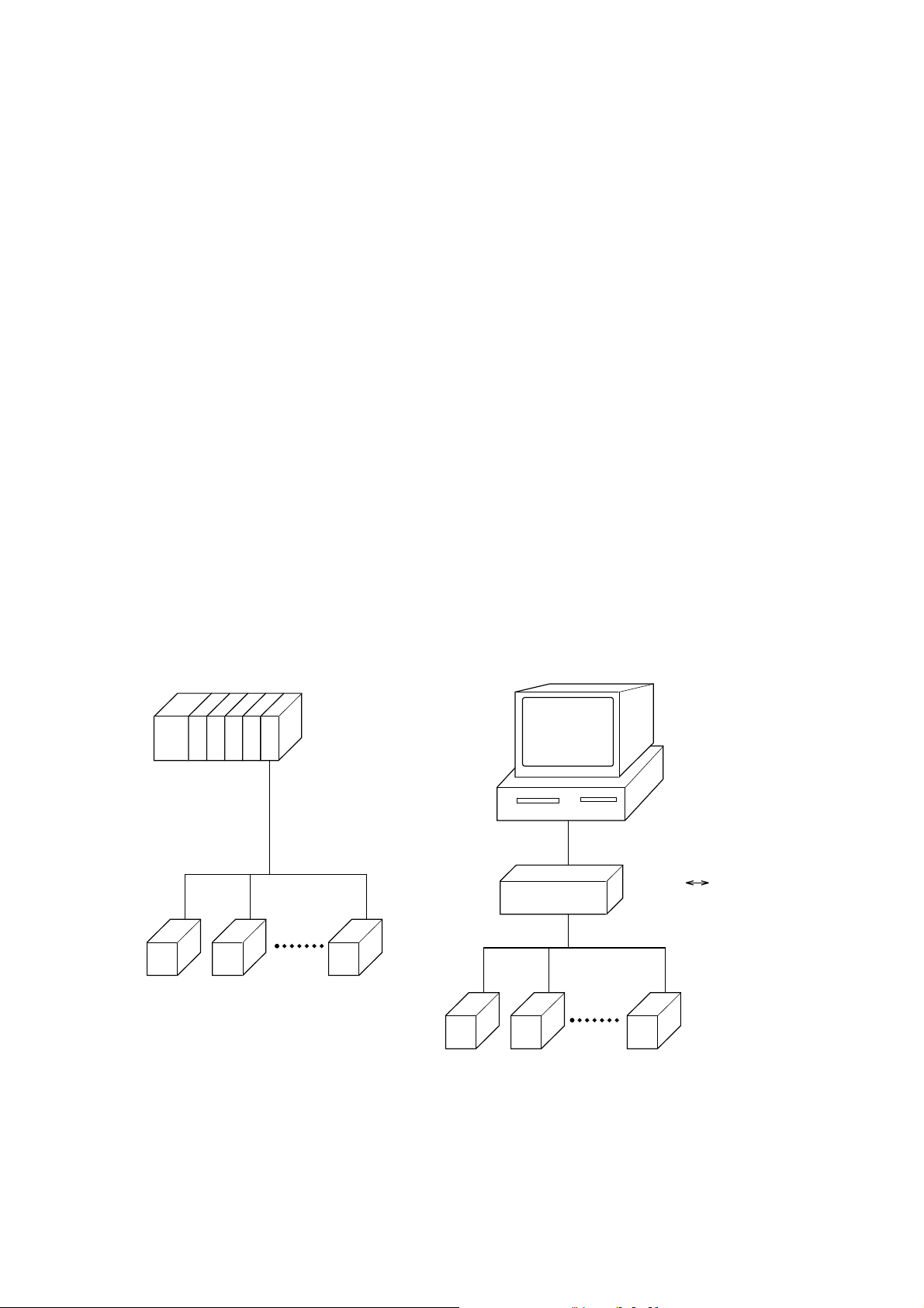
• The MODBUS slave communication function permits exchange of data with host computer, programmable
controller, graphic display panel, etc.
• The communication system consists of master station and slave stations. Up to 31 slave stations (PHL) can
be connected per master station.
Note that, because the master station can communicate with only one slave station at a time, a party to
communicate with must be specified by the “MODBUS Station No.” set at each slave station.
• In order that the master station and slave station can communicate, the format of the transmit/receive data must
coincide. For the PHL, the format of the communication data is determined by the MODBUS protocol.
• Please use an RS-232C ⇔ RS-485 converter in case of designating a personal computer or other devices which
have an RS-232C interface as a master station.
[RS-232C ⇔ RS-485 converter] (recommended article)
Type: K3SC-10 (isolated type)/ OMRON Corporation.
Programmable
controller
RS-485
RS-232C
RS-485
Caution:
When using the RS-232C ⇔ RS-485 converter, pay attention to cable connection between the converter and
master station. If the cable is not connected correctly, the master station and slave station cannot communicate.
In addition, be careful about communication settings such as baud rate and parity set for the converter.
Personal
computer
RS-232C RS-485 converter
- 1 -
Page 6

1.3 Overview of Ethernet communication functions
See Chapter 10 and Chapter 11 for the method for use of Ethernet communication functions in detail.
• The following functions are available as Ethernet communication functions.
(1) FTP server function
Permits take-out of files from the compact flash of the paperless recorder, using personal computer's
browser (Internet Explorer) or DOS prompt.
(2) Web server function
Permits check of measured values and event information recorded in the paperless recorder, using personal
computer's browser (Internet Explorer).
(3) E-mail send function
Permits E-mail transmission in a fixed period and also on occurrence of an alarm.
(4) MODBUS TCP/IP function
Permits exchange of data with host computer, programmable controller, graphic display panel, etc. by
MODBUS TCP/IP communication.
- 2 -
Page 7

2. SPECIFICATIONS
2.1 Communication Specifications
Item Specification
Electrical specification Based on EIA RS-485
Transmission system 2-wire, semi-duplicate
Synchronizing system Start-stop synchronous system
Connection format 1: N
Number connectable units Up to 31 units
Transmission distance 500 m max. (total extension distance)
Transmission speed 9600, 19200 bps
Data format Data length 8 bits
Stop bit 1 bit
Parity none, even, odd (selectable)
Transmission code HEX value (MODBUS RTU mode)
Error detection CRC-16
Isolation
Functional isolation between transmission circuit
and ground (withstand voltage: 500V AC)
- 3 -
Page 8
3. CONNECTION
WARNING
For avoiding electric shock and malfunctions, do not turn on the power supply untill all wiring
have been completed.
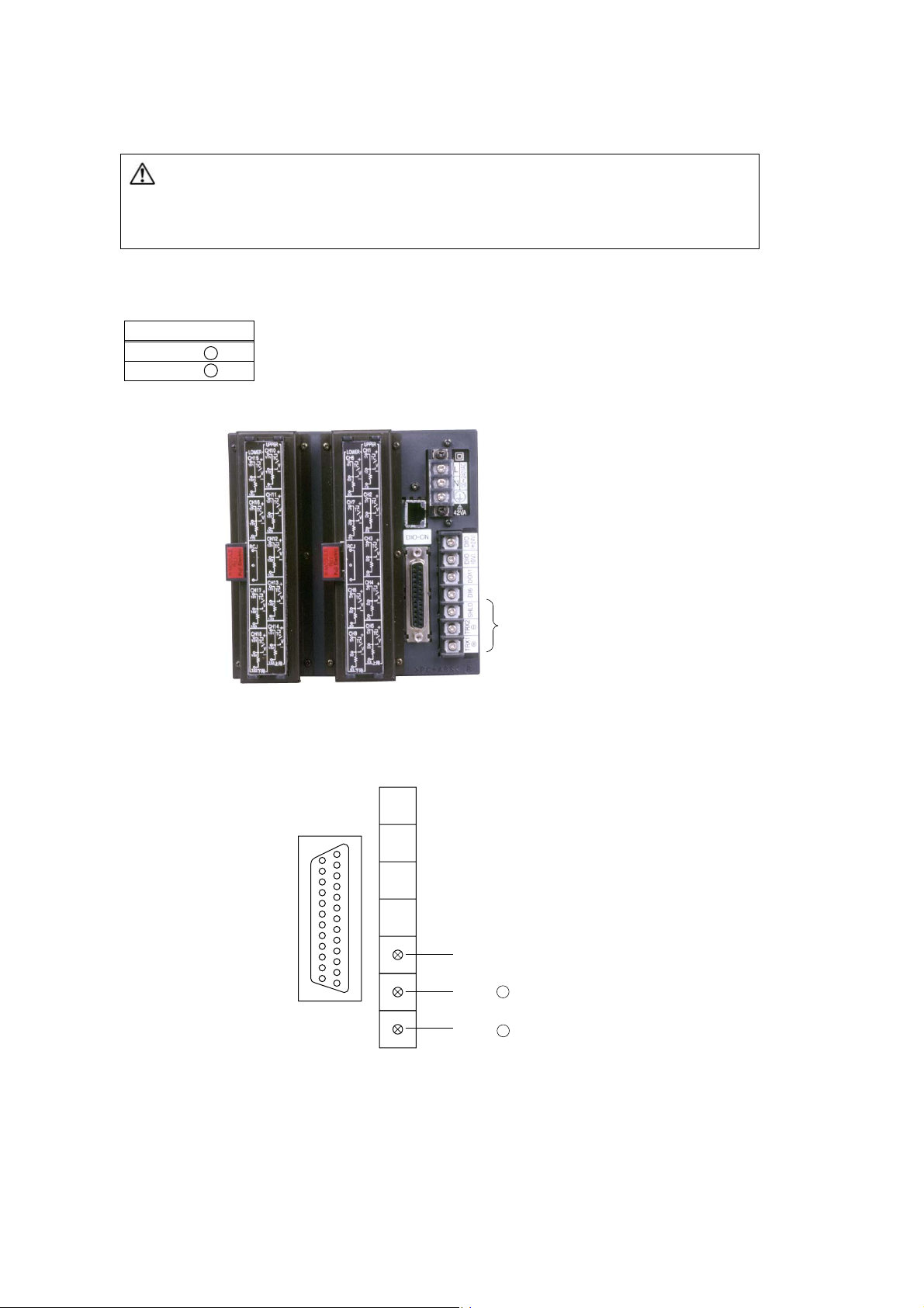
3.1 Communication Terminal Allocation
Signal name
TRX2 –
TRX1 +
Communication
Terminal
Communication Terminal
Shield
-
TRX2
TRX1 +
- 4 -
Page 9
3.2 Wiring
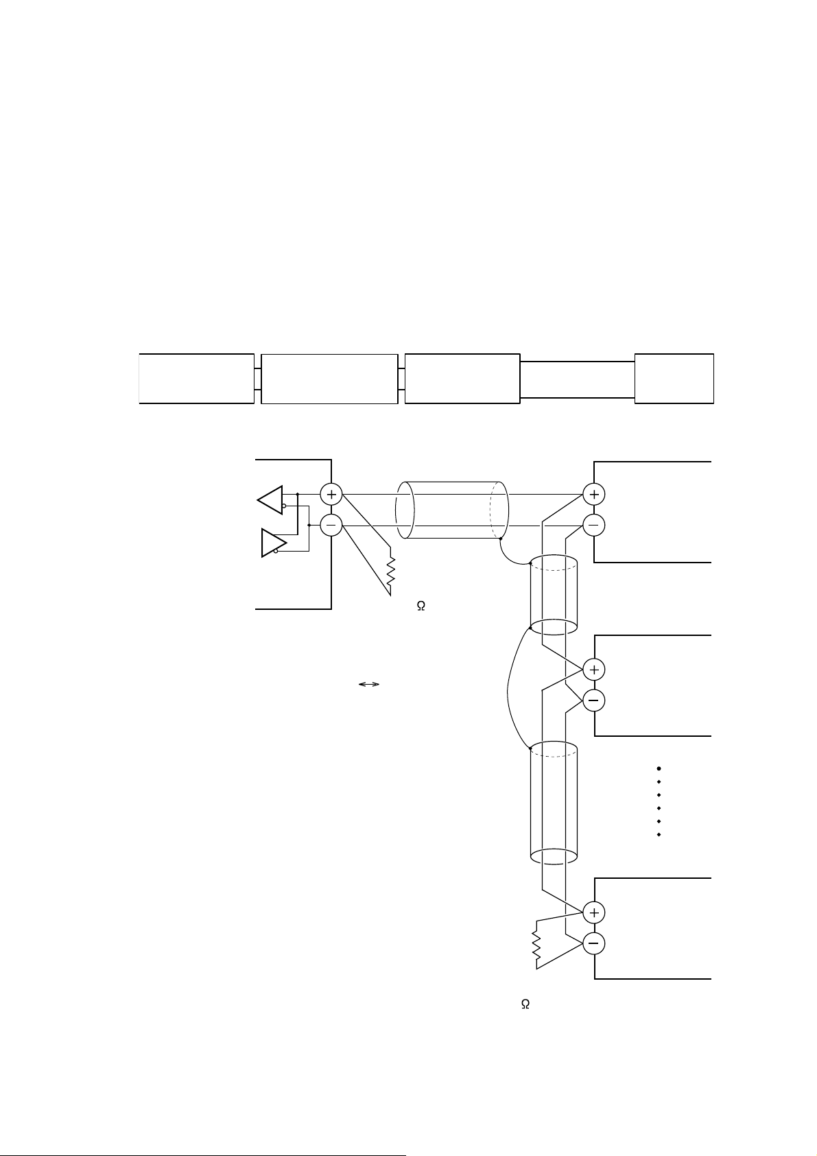
Use twisted pair cables with shield.
Recommended eable: UL2464, UL2448, etc.
• The total extension length of the cable is up to 500 m. A master station and up to 31 units of the PHL can be
connected per line.
• Both ends of the cable should be terminate with terminating resistors 100Ω (1/2W).
• The shield wire of the cable should be grounded at one place on the master station unit side.
• If the PHL is to be installed where the level of noise applied to the PHL may exceed 1000 V, it is recommended
to install a noise filter in the master station side as below.
Recommended noise filter: ZRAC2203-11/TDK
Master station
(PC, etc.)
RS-232C⇔RS-485
Master station side
Noise filter PHL
Transmission
cable
Slave station (PHL)
FG
RS-485 interface
or
RS-485 side of the RS-232C
(Recomended converter:
K3SC-10/OMRON Corporation)
Twisted pair cable with shield
Terminating resistor
100
(1/2W)
RS-485 converter
TRX1
TRX2
Slave station (PHL)
TRX1
TRX2
Slave station (PHL)
TRX1
TRX2
Terminating resistor
100 (1/2W)
- 5 -
Page 10

4.
In order that the master station and instrument (PHL) can correctly communicate, following settings are required.
• All communication condition settings of the master station are the same as those of instruments (PHL).
• All instruments (PHL) connected on a line are set to “ MODBUS Station No.” which are different from each
SETTING OF COMMUNICATION CONDITION
other. (Any “ MODBUS Station No.” is not shared by more than one instrument.)
4.1 Set Items
The parameters to be set are shown in the following table. Set them by operating the front panel keys.
Item
Station No. 1
Transmission
speed
Parity setting Odd
Data length
Stop bit
Value at
delivery
0 to 255
(0: communication function stop)
19200 bps 9600bps, 19200bps
None: None parity
Odd: Odd parity
Even: Even parity
8 bit
1 bit
Fixed (can not be changed)
Fixed (can not be changed)
Setting range Remarks
Set a different value to
each station.
Set the same communication condition to the
master station and all
stave stations.
- 6 -
Page 11

4.2 Setting Operation Method
The following example shows how to set the communication conditions.
Example: Selecting an even parity and “STno=10 and 9600bps” on a station.
Keys used Display Meanings
Trend display Operation state (Trend display)
SEL Menu
Press the [SEL] key to display the Menu screen.
ENT Parameter setting Press the [ENT] key to the Parameter setting screen.
ENT Basic setting
∨
ENT
∨
MODBUS Station NO
Numeric value entering
screen
<010>
ENT MODBUS Station NO
∨
ENT
∧
MODBUS baud rate
Baud rate selection
screen
9600
ENT MODBUS baud rate
∨
ENT
∨
MODBUS parity
Parity bit selection
screen
Even
Press the [ENT] key to the Basic setting screen.
Press the [
key pressed more than six times, use the [
Press the [ENT] key to display the Numeric value entering screen.
Use [<], [>] ,[∧], or [∨] key to change the numeric value to 10.
Press the [ENT] key to confirm the MODBUS Station NO.
Press the [∨] key to select the MODBUS baud rate.
∨] key six times to select MODBUS Station NO. (When the
∧] key to back)
Press the [ENT] key to display the Baud rate selection screen.
Press the [
Press the [ENT] key to confirm the baud rate.
Press the [∨] key to select the MODBUS parity.
Press the [ENT] key to display the Parity bit selection screen.
Press the [∨] key to select “Even”.
∧] key to select “9600”.
ENT MODBUS parity
DISP
ENT
Selection screen for
saving the settings
Confirmation screen for
saving the settings
ENT Trend display
Power OFF -
Power ON Trend display
Press [ENT] key to confirm the parity bit.
Press the [DISP] key to display a screen asking you want to save the
setting.
Press the [ENT] key to save the setting. (The confirmation screen
appears.)
The Trend screen appears.
Turn off the power.
Turn on the power once again to complete the setting.
- 7 -
Page 12

5. MODBUS COMMUNICATION PROTOCOL
5.1 General
The communication system by the MODBUS protocol is that the communication is always started from the master
station and a slave station responds to the received message.
Transmission procedures is as shown below.
1) The master station sends a command message to a slave station.
2) The slave station checks that the station No. in the received message matches with the own station No. or
not.
3) If matched, the slave station executes the command and sends back the response message.
4) If mismatched, the slave station leaves the command message and wait for the next command message.
a) In case when the station No. in the received command message matches with the own slave station No.
Master to slave
Slave to master
b) In case when the station No. in the received command message mismatches with the own slave station
No.
Master to slave
Slave to master
5) To assure safety, provide a structure where the response message is checked and retry is made three (3)
times or more if no response is made or an error occurs.
The master station can individually communicate with any one of slave stations connected on the same line upon
setting the station No. in the command message.
Command message
Command message
Response message
(Not respond)
Data on
the line
Data on
the line
- 8 -
Page 13

5.2 Composition of Message
Command message and response message consist of 4 fields ; Station No., Function code, Data and Error check
code. And these are send in this order.
Station No. (1 byte)
Function code (1 byte)
Data (2 to 133 bytes)
Error check code (CRC-16) (2 bytes)
Fig. 5-1 Composition of message
In the following, each field is explained.
(1) Station No
Station No. is the number specifiing a slave station. The command message is received and operated only by
the slave station whose station No. matches with the No. set in the parameter “ MODBUS Station No.”
For details of setting the parameter “ MODBUS Station No.”, refer to chapter 4.
(2) Function code
This is a code to designate the function executed at a slave station.
For details, refer to section 5.4.
(3) Data
Data are the data required for executing function codes. The composition of data varies with function codes.
For details, refer to chapter 6.
A register number is assigned to each data in the recorder. For reading/writing
the data by communication, designate the register number.
Note that the register number transmitted on message is expressed as its relative address.
The relative address is calculated by the following expression.
The lower 4 digits of the
Relative address
For example, when the resister number designated by a function code is 40003,
Relative address = (lower 4 digits of 40003)
= 0002
is used on the message.
=
register number
-
1
- 1
- 9 -
Page 14

(1) Error check code
This is the code to detect message errors (change in bit) in the signal transmission.
On the MODUBUS protocol (RTU mode), CRC-16 (Cycric Redundancy Check) is applied.
For CRC calculation method, refer to section 5.5.
- 10 -
Page 15

5.3 Response of Slave Station
(1) Response for normal command
To a relevant message, the slave station creates and sends back a response message which corresponds to the
command message. The composition of message in this case is the same as in section 5.2.
Contents of the data field depend on the function code. For details, refer to Chapter 6.
(2) Response for abnormal command
If contents of a command message have an abnormality (for example, non-actual function code is designated)
other than transmission error, the slave station does not execute that command but creates and sends back a
response message at error detection.
The composition of response message at error detection is as shown in Fig. 5-2 The value used for function
code field is function code of command message plus 80
Table 5-1 gives error codes.
Station No.
Function code + 80H
Error code
Error check (CRC-16)
.
H
Error code Contents Description
01H Illegal function code Non-actual function code is designated.
02H Illegal data address A relative address of a resister number to which the
03H Illegal data number Because the designation of number is too much,
(3) No response
Under any of the following items, the slave station takes no action of the command message and sends back no
response.
• A station number transmitted in the command message differs from the station number specified to the
slave station.
• A error check code is not matched, or a transmission error (parity error, etc.) is detected.
• The time interval between the composition data of the message becomes longer than the time
corresponding to 24 bits. (Refer to section 5.6 Transmission Control Procedure)
• Station No. of a slave station is set to 0.
Fig. 5-2 Response message at error detection
Table 5-1 Error Code
Check for the function code.
designated function code can not be used.
the area where resister numbers do not exist is
designated.
- 11 -
Page 16

5.4 Function Code
According to MODBUS protocol, register numbers are assigned by function codes.
Each function code acts on specific register number.
This correspondence is shown in Table5-2, and the message length by function is shown in Table5-3.
Table5-2 Correspondence between function codes and objective address
Function code
No. Function Object
03H
04H
10H
Function
code
03H Read-out of word data 64 words 8 8 7 133
04H
10H Write-in of continuous word data 64 words 11 137 8 8
Read-out
(continuously)
Read-out
(continuously)
Write-in
(continuously)
Contents
Read-out of word data
(read-out only)
Holding register
Input register
Holding register
Table5-3 Function code and message length
Number of
designatable
data
64 words 8 8 7 133
No. Contents
4xxxx Read-out/write-in word data
3xxxx Read-out word data
4xxxx Read-out/write-in word data
Command message Response message
Minimum Maximum Minimum Maximum
Resister No.
[Unit: byte]
- 12 -
Page 17
r
e
5.5 Calculation of Error Check Code (CRC-16)
CRC-16 is the 2-byte (16-bits) error check code. From the top of the message (station No.) to the end of the data
field are calculated.
The slave station calculates the CRC of the received message, and does not respond if the calculated CRC is
different from the contents of the received CRC code.
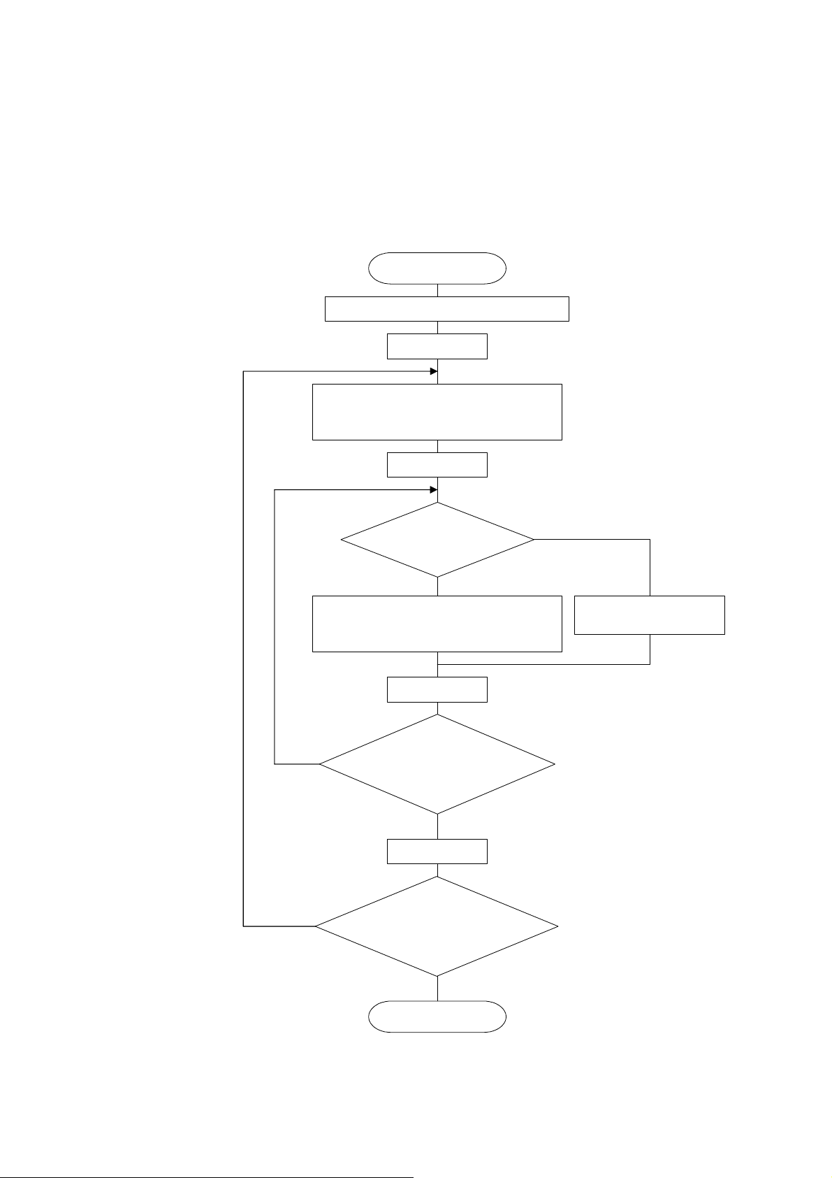
Fig. 5-3 shows the flow of the CRC-16 calculation system.
Set FFFFH (hexadecimal number) in CR.
Exclusive logical sum (XOR) is executed
with CR and one character (1 byte) of the I
characters, and its results is set in CR.
Start
Set 1 in I.
Set 1 in J.
Explanation of variables
CR : CRC error check data (2 bytes)
I : Digits of calculation characters
in command message
J : Check on the number of times
of CR calculation
Bit at right end
of CR is 1?
YES
Shift CR to right by 1 bit, and A001H and
exclusive logical sum (XOR) are executed
and its result is set in CR.
Add 1 to J.
NO
NO
Calculation (8 times)
is finished?
J>8
YES
Add 1 to I.
Calculation of all characters is
completed?
I>All characters
YES
End
NO
Shift CR to right by 1 bit.
(Calculation is executed in the orde
of command message station No.,
function code and data.)
CR calculation result shall be added
to the last command message in th
order of LOW byte and HIGH byte.
Fig. 5-3 Flow of CRC-16 calculation
- 13 -
Page 18

5.6 Transmission Control Procedure
(1) Transmission procedure of master station
The master station must proceed to a communication upon conforming to the following items.
(1-1) Before sending a command message, provide 48 bits time or more vacant status.
(1-2) For sending, the interval between bytes of a command message is below 24 bits time.
(1-3) Within 24 bits time after sending a command message, the receiving status is posted.
(1-4) Provide 48 bits time or more vacant status between the end of response message reception and
beginning of next command message sending [same as in (1-1)].
(1-5) For ensuring the safety, make a confirmation of the response message and make an arrangement so
as to provide 3 or more retries in case of no response, error occurrence, etc.
Note) The above definition is for most unfavorable value. For ensuring the safety, it’s recommended the
program of the master to work with safety factors of 2 to 3. Concretely, it is advised to arrange the
program for 9600 bps with 10 ms or more for vacant status (1-1), and within 1 ms for byte interval
(1-2) and changeover from sending to receiving (1-3).
(2) Description
1) Detection of the message frame
Since the communication system uses the 2-wire RS-485 interface, there may be 2 statuses on a line below.
(a) Vacant status (no data on line)
(b) Communication status (data is existing)
Instruments connected on the line are initially at a receiving status and monitoring the line. When 24 bits
time or more vacant status has appeared on the line, the end of preceding frame is assumed and, within
following 24 bits time, a receiving status is posted. When data appears on the line, instruments receive it
while 24 bits time or more vacant status is detected again, and the end of that frame is assumed. I.e., data
which appeared on the line from the first 24 bits time or more vacant status to the next 24 bits time or more
vacant status is fetched as one frame.
Therefore, one frame (command message) must be sent upon confirming the following.
(1-1) 48 bits time or more vacant status precedes the command message sending.
(1-2) Interval between bytes of 1 command message is smaller than 24 bits time.
2) Response of this instrument (PHL)
After a frame detection (24 bits time or more vacant status), this instrument carries out processing with that
frame as a command message. If the command message is destined to the own station, a response
message is returned. Its processing time is 300 to 500 ms (depends on contents of command message).
After sending a command message, therefore, the master station must observe the following
(1-3) Receiving status is posted within 24 bits time after sending a command message.
- 14 -
Page 19

Space time of longer than 5 ms is
needed.
(longer than 10 ms is recommended.)
Master
station
Master
station
→
← PHL
Data on line
PHL
POL1
500 ms max
POL1 response data
POL1 POL2 POL1 response data
POL2
- 15 -
Page 20
5.7 FIX Processing (Cautions in data write)
The instrument is provided inside with a non-volatile memory (F-ROM) for holding the setting parameters.
Data written in the non-volatile memory is not lost even if turning off the power.
To hold parameters that were written in the internal memory via communication after turning off the power, the FIX
process is effective. It allows parameters to be written in nonvolatile memory.
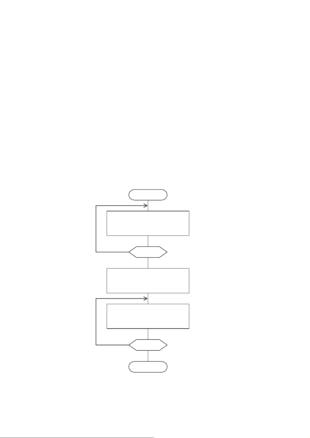
Fig.5-4 shows the FIX procedure.
Cautions:
•
Write in the non-volatile memory takes approximately 2 seconds.
• While writing, do not turn off the power of the PHL. Otherwise, the data in the non-volatile memory will be
destroyed, whereby the PHL could not be used any longer.
• Don’t change parameters on the front panel when performing the FIX procedure, or memory error may result.
• The non-volatile memory (F-ROM) is a device where the number of write-in times is limited. The
guaranteed number of write-in times of the non-volatile memory used on the instrument is 100,000 minimum.
Therefore, limit the times of change of parameter setting to absolute minimum. Refrain from carrying out
the FIX processing periodically for example or while such is not absolutely required.
Start FIX
Read the FIX data
with function code : 03
H
relative address : 1387
No
FIX=0?
Yes
Write ‘1’ into FIX data
with function code : 10
H
relative address : 1387
Read the FIX data
with function code : 03
H
relative address : 1387
No
FIX=0?
Yes
H
H
H
End FIX
Fig.5-4 FIX procedure
- 16 -
Page 21

6. DETAILS OF MESSAGE
6.1 Read-out of Word Data [Function code: 03H]
Function code
03H 64 words
Max. word number read-out
in one message
(1) Message composition
Command message composition (byte) Response message composition (byte)
Station No. Station No.
Function code Function code
Read-out start
No.
(relative address)
number
CRC data
* Arrangement of read-out word data
MSB LSB
Upper byte of contents of the first word data
Lower byte of contents of the first word data
Upper byte of contents of the next word data
Lower byte of contents of the next word data
~
Upper byte of contents of the last word data
Lower byte of contents of the last word data
Upper Read-out byte number Read-out word number×2
Lower Upper
Upper
Lower
Lower
Upper
(2) Function explanations
Relative data address Register No. Kind of data
0000H to 1386H 40001 to 44999 Storage enable data
to 176FH 45000 to 46000 Storage disable data
1387
H
Contents of the
1 to 64
first word data
Contents of the
next word data
~~
Contents of
the last word
data
CRC data
~
Lower Read-out word
Upper
Lower
Upper
Lower
Lower
Upper
Word data of continuous word numbers from the read-out start No. can be read. Read-out word data are
transmitted from the slave station in the order of upper and lower bytes.
- 17 -
Page 22

(3) Message transmission (example)
Reading range start and range end in Channel 1 from No. 2 station is shown below.
Relative address of range start in Channel 1: 001B
Command message composition (byte) Response message composition (byte)
Station No. 02
Function code 03H Function code 03H
Upper 00H Read-out byte number 04H Read-out start No.
(relative address)
number
CRC data
* Meaning of data to be read
Channel 1 Range start 00 00
(contents of the first word data)
Channel 1 Range end 0F A0
(contents of the next word data)
Where the unit is
°C with decimal point position set at 1,
Channel 1 Range start = 0.0
Channel 1 Range end = 400.0
Point
For “Point” decimal point, refer to Section 7.1
Lower 1B
Upper 00H
Lower 02
Lower B4H
Upper 3F
°C
°C
(Register No.40028), Data number: 02H
H
Station No. 02H
H
Upper 00H
H
H
Lower CCH
H
= 0
H
= 4000
H
Contents of the
first word data
Contents of the
next word data
CRC data
Lower 00H Read-out word
Upper 0FH
Lower A0H
Upper BBH
- 18 -
Page 23

6.2
Read-out of Read-out Only Word Data [Function code: 04H]
Function code
04H 64 words 0000H to 07CFH 30001 to 32000
(1) Message composition
Command message composition (byte) Response message composition (byte)
Station No. Station No.
Function code Function code
Read-out start No.
(relative address)
Read-out word
number
CRC data
* Arrangement of read-out word data
MSB LSB
Upper byte of contents of the first word data
Lower byte of contents of the first word data
Upper byte of contents of the next word data
Lower byte of contents of the next word data
~
Upper byte of contents of the last word data
Lower byte of contents of the last word data
(2) Function explanations
Max. word number read-out
in one message
Upper
Lower
Upper
Lower
Lower
Upper
Read-out byte number Read-out word number×2
Upper
1 to 64
Contents of the
first word data
Contents of the
next word data
~~
the last word
data
CRC data
Relative data address Register No.
Lower
Upper
Lower
Upper Contents of
Lower
Lower
Upper
~
Word data of continuous word numbers from the read-out start No. can be read. Read-out word data are
transmitted from the slave station in the order of upper and lower bytes.
- 19 -
Page 24

(3) Message transmission (example)
Reading measured values in Channel 2 from No. 1 station is shown below.
Relative address of measured value in Channel 2: 0065
Command message composition (byte) Response message composition (byte)
Station No. 01
Function code 04H Function code 04H
Upper 00H Read-out byte number 02H Read-out start No.
(relative address)
number
CRC data
* Meaning of data to be read
Channel 2 Measured value 01 4F
(contents of the first word data)
Where the unit is °C with decimal point position set at 1
Channel 2 Measured value = 33.5
Point
For “Point” decimal point, refer to Section 7.1.
Lower 65
Upper 00H
Lower 01
Lower 21H
Upper D5
°C
(Register No.30102), Data number: 01H
H
Station No. 01H
H
Upper 01H
H
H
H
= 335
H
Contents of the
first word data Lower 4FH Read-out word
CRC data
Lower F9H
Upper 54H
- 20 -
Page 25

6.3 Write-in of Continuous Word Data [Function code: 10H]
Function code
Max. word number write-in
in one message
10H 64 words
(1) Message composition
Command message composition (byte) Response message composition (byte)
Station No. Station No.
Function code Function code
Upper Upper Write-in start No.
(relative address)
number
Write-in byte number
Lower
Upper Upper Write-in word
Lower
Upper First write-in
word data
Lower
Upper Next write-in
word data
~ ~
Lower
Upper Last write-in
word data
CRC data
Lower
Lower
Upper
* Arrangement of write-in word data
MSB LSB
Upper byte of contents of the first word data
Lower byte of contents of the first word data
Upper byte of contents of the next word data
Lower byte of contents of the next word data
Upper byte of contents of the last word data
Lower byte of contents of the last word data
(2) Function explanation
Relative data address Register No. Kind of data
0000H to 1386H 40001 to 44999 Storage enable data
to 176FH 45000 to 46000 Storage disable data
1387
H
Write-in start No.
(relative address)
Lower
Write-in word
1 to 64
Write-in word number×2
number
CRC data
Lower
Lower
Upper
~~
Word data of continuous word number is written from write-in start address. Write-in word data are
transmitted from master station in the order of upper and lower bytes.
- 21 -
Page 26

(3) Message transmission (example)
Writing Subtract channel = channel 2, PV shift = 20.0°C, and PV gain = 110.0% in
Channel 1 of No. 1 station is shown below.
Subtract channel = 0002H (= 2D : channel 2)
PV shift = 00C8H (= 200D)
Input filter = 044CH (= 1100D)
Relative address of Subtract channel in Channel 1: 0014
Command message composition (byte) Response message composition (byte)
Station No. 01
Function code 10H Function code 10H
Upper 00H Upper 00H Write-in start No.
(relative address)
number
Write-in byte number 06H Lower 41H
word data
word data
word data
CRC data
Point
Caution
Since the transmission data can not include a decimal point, data of 110.0 is
transmitted as “1100”.
For transmission format of each data, refer to the address map (Chapter7)
If the write-in command message is sent to any slave station during the
FIX process, response is not returned from it.
Lower 14
Upper 00H Upper 00H Write-in word
Lower 03
Upper 00H
Lower 02
Upper 00H Next write-in
Lower C8
Upper 04H Last write-in
Lower 4C
Lower 5DH
Upper CB
(Register No.40021), Data number: 03H
H
Station No. 01H
H
Write-in start No.
H
H
H
H
H
H
(relative address)
Write-in word
number
CRC data
Lower 14H
Lower 03H
Upper CDH First write-in
- 22 -
Page 27

7. ADDRESS MAP AND DATA FORMAT
7.1 Data Format
7.1.1 Transmission data format
The MODBUS protocol used in this instrument (PHL) is RTU (Remote Terminal Unit) mode.
Transmitted data is “numeric value” and not “ASCII code”.
- 23 -
Page 28

7.1.2 Control of decimal point
A decimal point is not included on the transmission data.
Align decimal point for data that have decimal point (decimal point is eliminated in transmission, and added in
receiving).
7.1.3 Data with input error
When input error (Over, Under, Burnout or Error) occurs in display data, read data from measured values are as
follows.
Display data Read data
Over 32767
Under
Bunout
Error
Detection of input error during communication can be performed at address 30131 = Channel status.
-
32767
-
32768
-
32768
7.1.4 Range of write-in data
When data is written in each parameter, the write-in data should be kept within the setting range. PHL accepts the
write-in data beyond the range. However, be careful since the PHL performance will not be guaranteed.
- 24 -
Page 29

7.2 Address Map
For detailed contents about individual parameter function or setting range, refer to the operation manual.
Data type Long: long data The data of this address is manipulated in unit of word. 1 data/2 address
Word: word data The data of this address is manipulated in unit of word. 1 data/1 address
Byte: byte data The data of this address is manipulated in unit of byte. A maximum of 2 data/1 address
Bit: Bit data The data of this address is manipulated in unit of bit. A maximum of 16 data/1 address
7.2.1 Word data [read-out / write-in] : Function code [03H, 10H]
Register
No.
4XXXX
Data
type
40001 Byte 1st, 2nd characters Set Tag 1 (8 characters) by the ASCII code.
40002 Byte 3rd, 4th characters
40003 Byte 5th, 6th characters
40004 Byte
40005 Byte 1st, 2nd characters Set Tag 2 (8 characters) by the ASCII code.
40006 Byte 3rd, 4th characters
40007 Byte 5th, 6th characters
40008 Byte
40009 Word Color 1 to 14 (Please refer to Table 1.)
40010 Word Input type 0 to 33 (Please refer to Table 2.)
40011 Word Input filter 0 to 900 (0 to 900 sec)
40012 Word Unit 0 to 167 (Please refer to Table 3.)
40013 Word Scaling 0: OFF, 1: ON
40014 Word Masuring start
40015 Word Masuring end
40016 Word Engineering start
40017 Word Engineering end
40018 Word Decimal point 0 to 4 (Please refer to Table 5.)
40019 Word Square rooter 0: OFF, 1: ON
40020 Word Logarithmic display 0: OFF, 1: ON
40021 Word Subtract channel
40022 Word PV shift
40023 Word PV gain 0 to 32767 (0.00 to 327.67%)
40024 Word Reserve
40025 Word Reserve
40026 Word Recording mode 0: With record, 1: Display only
40027 Word Recording type 0: Min-Max rec., 1: Point record, 2: Average rec.
40028 Word Range start
40029 Word Range end
40030 Word Reserve
40031 Word Reserve
40032 Word Reserve
40033 Word Reserve
40034 Word Reserve
40035 Word Reserve
40036 Word Fvalue caluculation 0: OFF, 1: ON
40037 Word Totalize caluculation 0: OFF, 1: Totalizer, 2: Counter, 3: Timer
40038 Byte 1st, 2nd characters Set Totalize Tag (8 characters) by the ASCII code.
40039 Byte 3rd, 4th characters
40040 Byte 5th, 6th characters
40041 Byte
40042 Word Totalize unit 0 to 167 (Please refer to Table 3.)
40043 Word Totalize cut value
40044 Word Totalize scale value 1 to 32767
40045 Word Totalize type 0 to 6 (Please refer to Table 7.)
40046 Word External input 0 to 129 (Please refer to Table 8.)
40047 Word Totalize base time 0: /s, 1: /min, 2: /h, 3: /day
40048 Word Reset operation 0: OFF, 1: ON
40049 Word
Memory contents Read-out data / Write-in data setting range Remarks
Tag 1
7th, 8th characters
Tag 2
7th, 8th characters
-
1000 to 5500 (Please refer to Table 4.)
-
1000 to 5500 (Please refer to Table 4.)
-
32767 to 32767
-
32767 to 32767
Channel 1
setting
(64
words)
0 to 30 (0: Subtract OFF, 1 to 30: channel 1 to
30)
-
32767 to 32767
-
32767 to 32767 (Please refer to Table 6.)
-
32767 to 32767 (Please refer to Table 6.)
Totalize
tag
7th, 8th characters
-
32767 to 32767 (Please refer to Table 6.)
Totalize reset input 0 to 130 (Please refer to Table 9.)
- 25 -
Page 30

Register
No.
Data
type
40050 Word Reserve
to Reserve
40065 Word Channel 2 setting Same allocation as in Channel 1
to
40129 Word Channel 3 setting Same allocation as in Channel 1
to
40193 Word Channel 4 setting Same allocation as in Channel 1
to
40257 Word Channel 5 setting Same allocation as in Channel 1
to
40321 Word Channel 6 setting Same allocation as in Channel 1
to
40385 Word Channel 7 setting Same allocation as in Channel 1
to
40449 Word Channel 8 setting Same allocation as in Channel 1
to
40513 Word Channel 9 setting Same allocation as in Channel 1
to
40577 Word Channel 10 setting Same allocation as in Channel 1
to
40641 Word Channel 11 setting Same allocation as in Channel 1
to
40705 Word Channel 12 setting Same allocation as in Channel 1
to
40769 Word Channel 13 setting Same allocation as in Channel 1
to
40833 Word Channel 14 setting Same allocation as in Channel 1
to
40897 Word Channel 15 setting Same allocation as in Channel 1
to
40961 Word Channel 16 setting Same allocation as in Channel 1
to
41025 Word Channel 17 setting Same allocation as in Channel 1
to
41089 Word Channel 18 setting Same allocation as in Channel 1
to
41153 Word Channel 19 setting Same allocation as in Channel 1
to
41217 Word Channel 20 setting Same allocation as in Channel 1
to
41281 Word Channel 21 setting Same allocation as in Channel 1
to
41345 Word Channel 22 setting Same allocation as in Channel 1
to
41409 Word Channel 23 setting Same allocation as in Channel 1
to
41473 Word Channel 24 setting Same allocation as in Channel 1
to
41537 Word Channel 25 setting Same allocation as in Channel 1
to
41601 Word Channel 26 setting Same allocation as in Channel 1
to
41665 Word Channel 27 setting Same allocation as in Channel 1
to
41729 Word Channel 28 setting Same allocation as in Channel 1
to
41793 Word Channel 29 setting Same allocation as in Channel 1
to
41857 Word Channel 30 setting Same allocation as in Channel 1
to
Memory contents Read-out data / Write-in data setting range Remarks
- 26 -
Page 31

Register
No.
Data
type
41921 Word Alarm type 0: OFF, 1: H alarm, 2: L alarm
41922 Word Set point
41923 Word
41924 Word
41925 Word Alarm type 0: OFF, 1: H alarm, 2: L alarm
41926 Word Set point
41927 Word
41928 Word
41929 Word Alarm type 0: OFF, 1: H alarm, 2: L alarm
41930 Word Set point
41931 Word
41932 Word
41933 Word Alarm type 0: OFF, 1: H alarm, 2: L alarm
41934 Word Set point
41935 Word
41936 Word
41937 Word Channel 2 alarm setting Same allocation as in Channel 1
to
41953 Word Channel 3 alarm setting Same allocation as in Channel 1
to
41969 Word Channel 4 alarm setting Same allocation as in Channel 1
to
41985 Word Channel 5 alarm setting Same allocation as in Channel 1
to
42001 Word Channel 6 alarm setting Same allocation as in Channel 1
to
42017 Word Channel 7 alarm setting Same allocation as in Channel 1
to
42033 Word Channel 8 alarm setting Same allocation as in Channel 1
to
42049 Word Channel 9 alarm setting Same allocation as in Channel 1
to
42049 Word Channel 9 alarm setting Same allocation as in Channel 1
to
42065 Word Channel 10 alarm setting Same allocation as in Channel 1
to
42081 Word Channel 11 alarm setting Same allocation as in Channel 1
to
42097 Word Channel 12 alarm setting Same allocation as in Channel 1
to
42113 Word Channel 13 alarm setting Same allocation as in Channel 1
to
42129 Word Channel 14 alarm setting Same allocation as in Channel 1
to
42145 Word Channel 15 alarm setting Same allocation as in Channel 1
to
42161 Word Channel 16 alarm setting Same allocation as in Channel 1
to
42177 Word Channel 17 alarm setting Same allocation as in Channel 1
to
42193 Word Channel 18 alarm setting Same allocation as in Channel 1
to
42209 Word Channel 19 alarm setting Same allocation as in Channel 1
to
42225 Word Channel 20 alarm setting Same allocation as in Channel 1
to
42241 Word Channel 21 alarm setting Same allocation as in Channel 1
to
42257 Word Channel 22 alarm setting Same allocation as in Channel 1
to
42273 Word Channel 23 alarm setting Same allocation as in Channel 1
to
Memory contents Read-out data / Write-in data setting range Remarks
-
32767 to 32767 (Please refer to Table 6.)
-
32767 to 32767 (Please refer to Table 6.)
-
32767 to 32767 (Please refer to Table 6.)
-
32767 to 32767 (Please refer to Table 6.)
Channel 1
alarm
setting
(16
words)
Alarm
No.1
DO relay No. 0 to 28 (0: None, 1 to 28: DO1 to 28)
Alarm
No.2
DO relay No. 0 to 28 (0: None, 1 to 28: DO1 to 28)
Alarm
No.3
DO relay No. 0 to 28 (0: None, 1 to 28: DO1 to 28)
Alarm
No.4
DO relay No. 0 to 28 (0: None, 1 to 28: DO1 to 28)
Reserve
Reserve
Reserve
Reserve
- 27 -
Page 32

Register
No.
Data
type
42289 Word Channel 24 alarm setting Same allocation as in Channel 1
to
42305 Word Channel 25 alarm setting Same allocation as in Channel 1
to
42321 Word Channel 26 alarm setting Same allocation as in Channel 1
to
42337 Word Channel 27 alarm setting Same allocation as in Channel 1
to
42353 Word Channel 28 alarm setting Same allocation as in Channel 1
to
42369 Word Channel 29 alarm setting Same allocation as in Channel 1
to
42385 Word Channel 30 alarm setting Same allocation as in Channel 1
to
42401 Word Reserve
to Reserve
42425 Byte 1st, 2nd characters Set Display name (16 characters) by the ASCII code.
42426 Byte 3rd, 4th characters
42427 Byte 5th, 6th characters
42428 Byte 7th, 8th characters
42429 Byte 9th, 10th characters
42430 Byte 11th, 12th characters
42431 Byte 13th, 14th characters
42432 Byte
42433 Word Display No.1 0: None, 1 to 30: ch1 to 30
42434 Word Display No.2 0: None, 1 to 30: ch1 to 30
42435 Word Display No.3 0: None, 1 to 30: ch1 to 30
42436 Word Display No.4 0: None, 1 to 30: ch1 to 30
42437 Word Display No.5 0: None, 1 to 30: ch1 to 30
42438 Word Display No.6 0: None, 1 to 30: ch1 to 30
42439 Word Display No.7 0: None, 1 to 30: ch1 to 30
42440 Word Display No.8 0: None, 1 to 30: ch1 to 30
42441 Word Display No.9 0: None, 1 to 30: ch1 to 30
42442 Word
42443 Word Display group 2 setting Same allocation as Display group 1
to
42461 Word Display group 3 setting Same allocation as Display group 1
to
42479 Word Display group 4 setting Same allocation as Display group 1
to
42497 Word Reserve
42498 Word Trend direction 0: Vertical, 1: Horizontal
42499 Word Channel index 0: CH No.disp., 1: Tag No.disp., 2: Unit Disp.
42500 Word Scale display 0: OFF, 1: ON
42501 Word Reserve
42502 Word
42503 Word Display group 2 setting2 Same allocation as Display group 1
to
42508 Word Display group 3 setting2 Same allocation as Display group 1
to
42513 Word Display group 4 setting2 Same allocation as Display group 1
to
42518 Word Reserve
42519 Word Reserve
42520 Word Reserve
42521 Word
42522 Word Display group 2 setting2 Same allocation as Display group 1
to
42526 Word Display group 3 setting2 Same allocation as Display group 1
to
42530 Word Display group 4 setting2 Same allocation as Display group 1
to
42534 Word Reserve
to Reserve
Memory contents Read-out data / Write-in data setting range Remarks
Display
name
Display
group 1
setting
(18
words)
Display
group 1
setting2
(5 words)
Display
group 1
setting3
(4 words)
Display No.10 0: None, 1 to 30: ch1 to 30
Display divided 1 to 20
Analog meter 0: Bar graph, 1: Analog meter
15th, 16th characters
- 28 -
Page 33

Register
No.
Data
type
42541 Word Totalize base time 0 to 1439 (0 to 1439min = 00:00 to 23:59)
42542 Word Totalize cycle 0 to 9 (Please refer to Table 10.)
42543 Word Weekly base day 0 to 6 (Please refer to Table 11.)
42544 Word Monthly base day 1 to 31 (1 to 31day)
42545 Word Dayly (time) start time 0 to 1439 (0 to 1439min = 00:00 to 23:59)
42546 Word Dayly (time) stop time 0 to 1439 (0 to 1439min = 00:00 to 23:59)
42547 Word External input 0 to 129 (Please refer to Table 8.)
42548 Word H-P, L-P timer cycle 1 to 32767 (1 to 32767min)
42549 Word AVG timer cycle 1 to 32767 (1 to 32767min)
42550 Word SUM timer cycle 1 to 32767 (1 to 32767min)
42551 Word Formula1 1st calculation (Please refer to Table 12.)
42552 Word argument1
42553 Word argument2
42554 Word Formula1 2nd calculation
42555 Word argument1
42556 Word argument2
42557 Word Formula1 3rd calculation
42558 Word argument1
42559 Word argument2
42560 Word Formula2 1st calculation
42561 Word argument1
42562 Word argument2
to
42584 Word Formula4 3rd calculation
42585 Word argument1
42586 Word
42587 Word Math channel 20 setting Same allocation as Channel 19
to
42623 Word Math channel 21 setting Same allocation as Channel 19
to
42659 Word Math channel 22 setting Same allocation as Channel 19
to
42695 Word Math channel 23 setting Same allocation as Channel 19
to
42731 Word Math channel 24 setting Same allocation as Channel 19
to
42767 Word Math channel 25 setting Same allocation as Channel 19
to
42803 Word Math channel 26 setting Same allocation as Channel 19
to
42839 Word Math channel 27 setting Same allocation as Channel 19
to
42875 Word Math channel 28 setting Same allocation as Channel 19
to
42911 Word Math channel 29 setting Same allocation as Channel 19
to
42947 Word Math channel 30 setting Same allocation as Channel 19
to
42983 Word Constant1 Value
42984 Word Dicimal point 0 to 4
to
43021 Word Constant20 Value
43022 Word Dicimal point 0 to 4
43023 Word Reserve
to Reserve
43032 Word Time setting Time set request 1: Time set request.(Automatically clear)
43033 Word Time setting Year 1 to 99 (2001 to 2099year)
43034 Word Month 1 to 12 (1 to 12month)
43035 Word Day 1 to 31 (1 to 31day)
43036 Word Hour 0 to 23 (0 to 23hour)
43037 Word Minute 0 to 59 (0 to 59minute)
43038 Word Reserve
43039 Word Reserve
43040 Word Refreshment cycle 0 to 19 (Please refer to Table 14.)
Memory contents Read-out data / Write-in data setting range Remarks
Math
CH 19
setting
(36
words)
argument2
-
32767 to 32767 (Please refer to Table 13.)
-
32767 to 32767 (Please refer to Table 13.)
Attention:
Don’t change the
time absolutely
during recording
and totalizing.
- 29 -
Page 34

Register
No.
Data
type
43041 Word Reserve
43042 Word LCD lights-out time 0 to 60 (0: ON all the time, 1 to 60: 1 to 60min)
43043 Word File division cycle 0 to 4 (Please refer to Table 15.)
43044 Word Memory full alarm 0 to 28 (0: None, 1 to 28: DO1 to 28)
43045 Word Record data format 0: Ascii, 1: Binary
43046 Word Target temperture
43047 Word Z value
43048 Word Decimal point 0 to 4 (Please refer to Table 16.)
43049 Word Reserve
43050 Word
43051 Word Battery alarm 0 to 28 (0: None, 1 to 28: DO1 to 28)
43052 Word Data format 0 to 4 (Please refer to Table 17.)
43053 Word File overwrite 0: OFF, 1: ON
43054 Word Display compression 0: 1/1, 1: 1/10, 2: 1/30, 3: 1/60
43055 Word Select language 0: English, 1: French
43056 Word Alarm hysteresis 0 to 10000 (0.00 to 100.00%)
43057 Word Alarm latch 0: OFF, 1: ON
43058 Word MODBUS Station No. 0 to 255 (0: Communication OFF)
43059 Word MODBUS baud rate 0: 9600bps, 1: 19200bps
43060 Word MODBUS parity 0: None, 1: Odd, 2: Even
43061 Word Configuration password 0 to 9999
43062 Word CF manager password 0 to 9999
43063 Word Record password 0 to 9999
43064 Word Security mode 0: Password, 1: Logon
43065 Word Reserve
43066 Word Reserve
43067 Word Trend back color 0: White, 1: Black
43068 Word Historical back color 0: White, 1: Black
to Reserve
43081 Byte Messege 1st, 2nd characters Set Message (32 characters) by the ASCII code.
43082 Byte 3rd, 4th characters
43083 Byte 5th, 6th characters
43084 Byte 7th, 8th characters
43085 Byte 9th, 10th characters
43086 Byte 11th, 12th characters
43087 Byte 13th, 14th characters
43088 Byte 15th, 16th characters
43089 Byte 17th, 18th characters
43090 Byte 19th, 20th characters
43091 Byte 21th, 22th characters
43092 Byte 23th, 24th characters
43093 Byte 25th, 26th characters
43094 Byte 27th, 28th characters
43095 Byte 29th, 30th characters
43096 Byte 31th, 32th characters
43097 Word Reserve
43098 Word Reserve
43099 Word Messege timing 0 to 2 (Please refer to Table 18.)
43100 Word Messege timing argument 1
43101 Word Messege timing argument 2
43102 Word
43103 Word Messege No.2 setting Same allocation as Message No. 1
to
43125 Word Messege No.3 setting Same allocation as Message No. 1
to
43147 Word Messege No.4 setting Same allocation as Message No. 1
to
43169 Word Messege No.5 setting Same allocation as Message No. 1
to
43191 Word Messege No.6 setting Same allocation as Message No. 1
to
43213 Word Messege No.7 setting Same allocation as Message No. 1
to
Memory contents Read-out data / Write-in data setting range Remarks
FValue calculation
Message
No.1
setting
(22
Word s)
Reserve
Reset temperature
-
32767 to 32767 (-3276.7 to 3276.7°C)
-
32767 to 32767 (-3276.7 to 3276.7°C)
-
32767 to 32767 (-3276.7 to 3276.7°C)
- 30 -
Page 35

Register
No.
Data
type
43235 Word Messege No.8 setting Same allocation as Message No. 1
to
43257 Word Messege No.9 setting Same allocation as Message No. 1
to
43279 Word Messege No.10 setting Same allocation as Message No. 1
to
43301 Byte 1st, 2nd characters Set original unit (7 characters) by the ASCII code.
43302 Byte 3rd, 4th characters
43303 Byte 5th, 6th characters
43304 Byte 7th, characters
43305 Byte Reserve
43306 Byte Reserve
43307 Byte
43308 Byte Original unit 2 setting Same allocation as Original unit 1
to
43315 Byte Original unit 3 setting Same allocation as Original unit 1
to
43322 Byte Original unit 4 setting Same allocation as Original unit 1
to
43329 Byte Original unit 5 setting Same allocation as Original unit 1
to
43336 Byte Original unit 6 setting Same allocation as Original unit 1
to
43343 Byte Original unit 7 setting Same allocation as Original unit 1
to
43350 Byte Original unit 8 setting Same allocation as Original unit 1
to
43357 Byte Original unit 9 setting Same allocation as Original unit 1
to
43364 Byte Original unit 10 setting Same allocation as Original unit 1
to
43371 Byte Original unit 11 setting Same allocation as Original unit 1
to
43378 Byte Original unit 12 setting Same allocation as Original unit 1
to
43385 Word
to
43496 Word DI 1 function 0 to 5 (Please refer to Table 19.)
43497 Word DI 2 function 0 to 5
43498 Word DI 3 function 0 to 5
43499 Word DI 4 function 0 to 5
43500 Word DI 5 function 0 to 5
43501 Word DI 6 function 0 to 5
43502 Word DI 7 function 0 to 5
43503 Word DI 8 function 0 to 5
43504 Word DI 9 function 0 to 5
43505 Word DI 10 function 0 to 5
43506 Word RCJ ON/OFF 0: OFF, 1: ON
43507 Word Reserve
43508 Word Reserve
43509 Word Reserve
43510 Word Front communication 0: OFF, 1: ON
43511 Word Rec.start adjust OFF 0: OFF, 1: ON
43512 Word Do not write
to Do not write
Memory contents Read-out data / Write-in data setting range Remarks
Original unit 1 setting
Reserve
Reserve
Reserve
- 31 -
Page 36

Register
No.
Data
type
44001 Byte 1st, 2nd characters Do not write
44002 Byte 3rd, 4th characters Do not write
44003 Byte 5th, 6th characters Do not write
44004 Byte 7th, 8th characters Do not write
44005 Byte 9th, 10th characters Do not write
44006 Byte 11th, 12th characters Do not write
44007 Byte 13th, 14th characters Do not write
44008 Byte 15th, 16th characters Do not write
44009 Byte 17th, 18th characters Do not write
44010 Byte 19th, 20th characters Do not write
44011 Byte 21th, 22th characters Do not write
44012 Byte 23th, 24th characters Do not write
44013 Byte 25th, 26th characters Do not write
44014 Byte 27th, 28th characters Do not write
44015 Byte 29th, 30th characters Do not write
44016 Byte
44017 Byte 1st, 2nd characters Do not write
44018 Byte 3rd, 4th characters Do not write
44019 Byte 5th, 6th characters Do not write
44020 Byte 7th, 8th characters Do not write
44021 Byte 9th, 10th characters Do not write
44022 Byte 11th, 12th characters Do not write
44023 Byte 13th, 14th characters Do not write
44024 Byte
44025 Word Do not write
to Do not write
Memory contents Read-out data / Write-in data setting range Remarks
PILC data
31th, 32th characters Do not write
Serial number
15th, 16th characters Do not write
Following register No. 45000 to 45500 will not be recorded in the main unit.
Register
No.
Data
type
45000 Word Register data request 1: Register data (Automatically clear)
45001 Word Reserve
45002 Word Fvalue calculation reset request 1: Fvalue reset (Automatically clear)
45003 Word Prohibiting the writing to the memory card 0: Writing permission, 1: Writing prohibition
45004 Bit Recorder control (Please refer to Table 20.)
45005 Bit Message request (Please refer to Table 21.)
45006 Word Totalize reset request 1: Totalize reset (Automatically clear)
45007 Word Alarm latch clear request 1: Alarm latch clear (Automatically clear)
45008 Word Do not write
to Do not write
45051 Bit Totalize reset request Channel 1 to 16 (Please refer to Table 22.)
45052 Bit of each channel Channel 17 to 30
45053 Word
to Word
45061 Word Communication input 1 : M01
45062 Word Communication input 2 : M02
45063 Word Communication input 3 : M03
45064 Word Communication input 4 : M04
45065 Word Communication input 5 : M05
45066 Word Communication input 6 : M06
45067 Word Communication input 7 : M07
45068 Word Communication input 8 : M08
45069 Word Communication input 9 : M09
45070 Word Communication input10 : M10
45071 Word Communication input11 : M11
45072 Word Communication input12 : M12
to Do not write
Memory contents Read-out data / Write-in data setting range Remarks
-
32767 to 32767
-
32767 to 32767
-
32767 to 32767
-
32767 to 32767
-
32767 to 32767
-
32767 to 32767
-
32767 to 32767
-
32767 to 32767
-
32767 to 32767
-
32767 to 32767
-
32767 to 32767
-
32767 to 32767
Reserve
Reserve
- 32 -
Page 37

The following addresses are recorded in the main unit.
Register
No.
Data
type
45501 Word Reserve
45502 Word E-mail function 0: OFF, 1. ON
45503 Word FTP server function 0: OFF, 1: ON
45504 Word FTP access control 0: OFF, 1: ON
45505 Word Web server function 0: OFF, 1: ON
45506 Word Reserve
45507 Word Reserve
45508 Word MODBUS TCP/IP function 0: OFF, 1. ON
45509 Word IP address 1st number 0 to 255
45510 Word 2nd number 0 to 255
45511 Word 3rd number 0 to 255
45512 Word 4th number 0 to 255
45513 Word Subnet mask 1st number 0 to 255
45514 Word 2nd number 0 to 255
45515 Word 3rd number 0 to 255
45516 Word 4th number 0 to 255
45517 Word Default gateway 1st number 0 to 255
45518 Word 2nd number 0 to 255
45519 Word 3rd number 0 to 255
45520 Word 4th number 0 to 255
45521 Word SMTP IP address 1st number 0 to 255
45522 Word 2nd number 0 to 255
45523 Word 3rd number 0 to 255
45524 Word 4th number 0 to 255
45525 Byte Sender’s mall address 1st, 2nd characters Set address (64 characters) by the ASCII code.
45526 Byte 3rd, 4th characters
45527 Byte 5th, 6th characters
45528 Byte 7th, 8th characters
45529 Byte 9th, 10th characters
45530 Byte 11th, 12th characters
45531 Byte 13th, 14th characters
45532 Byte 15th, 16th characters
45533 Byte 17th, 18th characters
45534 Byte 19th, 20th characters
45535 Byte 21th, 22th characters
45536 Byte 23th, 24th characters
45537 Byte 25th, 26th characters
45538 Byte 27th, 28th characters
45539 Byte 29th, 30th characters
45540 Byte 31th, 32th characters
45541 Byte 33th, 34th characters
45542 Byte 35th, 36th characters
45543 Byte 37th, 38th characters
45544 Byte 39th, 40th characters
45545 Byte 41th, 42th characters
45546 Byte 43th, 44th characters
45547 Byte 45th, 46th characters
45548 Byte 47th, 48th characters
45549 Byte 49th, 50th characters
45550 Byte 51th, 52th characters
45551 Byte 53th, 54th characters
45552 Byte 55th, 56th characters
45553 Byte 57th, 58th characters
45554 Byte 59th, 60th characters
45555 Byte 61th, 62th characters
45556 Byte 63th, 64th characters
45557 Byte Sender’s mail name 1st, 2nd characters Set name (32 characters) by the ASCII code.
45558 Byte 3rd, 4th characters
45559 Byte 5th, 6th characters
Memory contents Read-out data / Write-in data setting range Remarks
- 33 -
Page 38

Register
No.
Data
type
45560 Byte 7th, 8th characters
45561 Byte 9th, 10th characters
45562 Byte 11th, 12th characters
45563 Byte 13th, 14th characters
45564 Byte 15th, 16th characters
45565 Byte 17th, 18th characters
45566 Byte 19th, 20th characters
45567 Byte 21th, 22th characters
45568 Byte 23th, 24th characters
45569 Byte 25th, 26th characters
45570 Byte 27th, 28th characters
45571 Byte 29th, 30th characters
45572 Byte 31th, 32th characters
45573 Byte Receiver’s mail 1st, 2nd characters Set address (64 characters) by the ASCII code.
45574 Byte address 1 3rd, 4th characters
45575 Byte 5th, 6th characters
45576 Byte 7th, 8th characters
45577 Byte 9th, 10th characters
45578 Byte 11th, 12th characters
45579 Byte 13th, 14th characters
45580 Byte 15th, 16th characters
45581 Byte 17th, 18th characters
45582 Byte 19th, 20th characters
45583 Byte 21th, 22th characters
45584 Byte 23th, 24th characters
45585 Byte 25th, 26th characters
45586 Byte 27th, 28th characters
45587 Byte 29th, 30th characters
45588 Byte 31th, 32th characters
45589 Byte 33th, 34th characters
45590 Byte 35th, 36th characters
45591 Byte 37th, 38th characters
45592 Byte 39th, 40th characters
45593 Byte 41th, 42th characters
45594 Byte 43th, 44th characters
45595 Byte 45th, 46th characters
45596 Byte 47th, 48th characters
45597 Byte 49th, 50th characters
45598 Byte 51th, 52th characters
45599 Byte 53th, 54th characters
45600 Byte 55th, 56th characters
45601 Byte 57th, 58th characters
45602 Byte 59th, 60th characters
45603 Byte 61th, 62th characters
45604 Byte 63th, 64th characters
45605 Byte Receiver's mail address 2 Same allocation as Receiver's mail address 1
to
45637 Byte Receiver's mail address 3 Same allocation as Receiver's mail address 1
to
45669 Byte Receiver's mail address 4 Same allocation as Receiver's mail address 1
to
45701 Byte Receiver's mail address 5 Same allocation as Receiver's mail address 1
to
45733 Byte Receiver's mail address 6 Same allocation as Receiver's mail address 1
to
45765 Byte Receiver's mail address 7 Same allocation as Receiver's mail address 1
to
45797 Byte Receiver's mail address 8 Same allocation as Receiver's mail address 1
to
45829 Word Reserve
to Reserve
45901 Byte User1 User name 1st, 2nd characters Set name (16 characters) by the ASCII code.
45902 Byte setting 3rd, 4th characters
45903 Byte 5th, 6th characters
Memory contents Read-out data / Write-in data setting range Remarks
- 34 -
Page 39

Register
No.
Data
type
45904 Byte 7th, 8th characters
45905 Byte 9th, 10th characters
45906 Byte 11th, 12th characters
45907 Byte 13th, 14th characters
45908 Byte 15th, 16th characters
45909 Byte Password 1st, 2nd characters Set name (8 characters) by the ASCII code.
45910 Byte 3rd, 4th characters
45911 Byte 5th, 6th characters
45912 Byte 7th, 8th characters
45913 Word User level
45914 Word Reserve
45915 Byte User 2 setting Same allocation as User 1
to
45929 Byte User 3 setting Same allocation as User 1
to
45943 Byte User 4 setting Same allocation as User 1
to
45957 Byte User 5 setting Same allocation as User 1
to
45971 Byte User 6 setting Same allocation as User 1
to
45985 Byte User 7 setting Same allocation as User 1
to
45999 Byte User 8 setting Same allocation as User 1
to
46013 Word Reserve
to Reserve
46101 Byte E-mail Title 1st, 2nd characters Set title (32 characters) by the ASCII code.
46102 Byte trigger 1 3rd, 4th characters
46103 Byte setting 5th, 6th characters
46104 Byte 7th, 8th characters
46105 Byte 9th, 10th characters
46106 Byte 11th, 12th characters
46107 Byte 13th, 14th characters
46108 Byte 15th, 16th characters
46109 Byte 17th, 18th characters
46110 Byte 19th, 20th characters
46111 Byte 21th, 22th characters
46112 Byte 23th, 24th characters
46113 Byte 25th, 26th characters
46114 Byte 27th, 28th characters
46115 Byte 29th, 30th characters
46116 Byte 31th, 32th characters
46117 Byte Text 1 1st, 2nd characters Set text 1 (32 characters) by the ASCII code.
46118 Byte 3rd, 4th characters
46119 Byte 5th, 6th characters
46120 Byte 7th, 8th characters
46121 Byte 9th, 10th characters
46122 Byte 11th, 12th characters
46123 Byte 13th, 14th characters
46124 Byte 15th, 16th characters
46125 Byte 17th, 18th characters
46126 Byte 19th, 20th characters
46127 Byte 21th, 22th characters
46128 Byte 23th, 24th characters
46129 Byte 25th, 26th characters
46130 Byte 27th, 28th characters
46131 Byte 29th, 30th characters
46132 Byte 31th, 32th characters
46133 Byte Text 2 1st, 2nd characters Set text 2 (32 characters) by the ASCII code.
46134 Byte 3rd, 4th characters
46135 Byte 5th, 6th characters
46136 Byte 7th, 8th characters
46137 Byte 9th, 10th characters
Memory contents Read-out data / Write-in data setting range Remarks
0: Administrator, 1: Engineer, 2: Operator,
3: Guest
- 35 -
Page 40

Register
No.
Data
type
46138 Byte 11th, 12th characters
46139 Byte 13th, 14th characters
46140 Byte 15th, 16th characters
46141 Byte 17th, 18th characters
46142 Byte 19th, 20th characters
46143 Byte 21th, 22th characters
46144 Byte 23th, 24th characters
46145 Byte 25th, 26th characters
46146 Byte 27th, 28th characters
46147 Byte 29th, 30th characters
46148 Byte 31th, 32th characters
46149 Word Trigger timing (Please refer to Table 23.)
46150 Word Trigger timing argument 1
46151 Word Trigger timing argument 2
46152 Word PV value affixation 0: OFF, 1: ON
46153 Word Receiver's mail address No. (Please refer to Table 24.)
46154 Word Reserve
46155 Byte E-mail trigger 2 setting Same allocation as E-mail trigger 1
to
46209 Byte E-mail trigger 3 setting Same allocation as E-mail trigger 1
to
46263 Byte E-mail trigger 4 setting Same allocation as E-mail trigger 1
to
46317 Byte E-mail trigger 5 setting Same allocation as E-mail trigger 1
to
46371 Byte E-mail trigger 6 setting Same allocation as E-mail trigger 1
to
46425 Byte E-mail trigger 7 setting Same allocation as E-mail trigger 1
to
46479 Byte E-mail trigger 8 setting Same allocation as E-mail trigger 1
to
46533 Byte E-mail trigger 9 setting Same allocation as E-mail trigger 1
to
46587 Byte E-mail trigger 10 setting Same allocation as E-mail trigger 1
to
46641 Word Reserve
to Reserve
47000 Word Final address Reserve
Memory contents Read-out data / Write-in data setting range Remarks
- 36 -
Page 41

7.2.2 Word data [read-out only] : Function code [04H]
Register
No.
3xxxx
Data
type
30001 Bit System information (Please refer to Table 25.)
30002 Bit Reserve
30003 Bit DO information DO 1 to 16 (Please refer to Table 26.)
30004 Bit DO 17 to 28
30005 Bit Reserve
30006 Bit DI information (Please refer to Table 27.)
to Reserve
30086 Word Memory cord utilization 0 to 1000 (0.00 to 100.0%, 100.0% = Memory Full)
to Reserve
30093 Bit Channel 1 to 4 (Please refer to Table 28.)
30094 Bit Channel 5 to 8
30095 Bit Channel 9 to 12
30096 Bit Channel 13 to 16
30097 Bit Channel 17 to 20
30098 Bit Channel 21 to 24
30099 Bit Channel 25 to 28
30100 Bit
30101 Word Channel 1
30102 Word Channel 2
30103 Word Channel 3
to
30129 Word Channel 29
30130 Word
30131 Word Channel 1 0: Normal, 1: Burnout, 2: Over, 3: Under, 4: Error
30132 Word Channel 2 0: Normal, 1: Burnout, 2: Over, 3: Under, 4: Error
30133 Word Channel 3 0: Normal, 1: Burnout, 2: Over, 3: Under, 4: Error
to
30160 Word
30161 Long Totalizing value Channel 1
30162 Long Channel 1
30163 Long Channel 2
30164 Long Channel 2
to
30219 Long Channel 30
30220 Long Channel 30
30221 Long Totalizing start time Channel 1 Greenwich Time
30222 Long Channel 1
30223 Long Channel 2 Greenwich Time
30224 Long Channel 2
to
30279 Long Channel 30 Greenwich Time
30280 Long Channel 30
30281 Long Totalizing end time Channel 1 Greenwich Time
30282 Long Channel 1
30283 Long Channel 2 Greenwich Time
30284 Long Channel 2
to
30339 Long Channel 30 Greenwich Time
30340 Long Channel 30
30341 Long Previous totalized Channel 1
30342 Long value Channel 1
30343 Long Channel 2
30344 Long Channel 2
to
30399 Long Channel 30
30400 Long Channel 30
30401 Long Previous totalized Channel 1 Greenwich Time
30402 Long start time Channel 1
30403 Long Channel 2 Greenwich Time
30404 Long Channel 2
to
Memory contents Read-out data Remarks
Channel Alarm
information
Channel 29 to 30
-
32767 to 32767 (No decimal point)
-
32767 to 32767 (No decimal point)
-
Measured value
Channel 30
Channel status
Channel 30 0: Normal, 1: Burnout, 2: Over, 3: Under, 4: Error
32767 to 32767 (No decimal point)
-
32767 to 32767 (No decimal point)
-
32767 to 32767 (No decimal point)
-
999999999 to 999999999 (No decimal point)
-
999999999 to 999999999 (No decimal point)
-
999999999 to 999999999 (No decimal point)
-
999999999 to 999999999 (No decimal point)
-
999999999 to 999999999 (No decimal point)
-
999999999 to 999999999 (No decimal point)
- 37 -
Page 42

Register
No.
Data
type
30459 Long Channel 30 Greenwich Time
30460 Long Channel 30
30461 Long Previous totalized Channel 1 Greenwich Time
30462 Long end time Channel 1
30463 Long Channel 2 Greenwich Time
30464 Long Channel 2
to
30519 Long Channel 30 Greenwich Time
30520 Long Channel 30
30521 Word Reserve
to Reserve
32000 Word Final address Reserve
Memory contents Read-out data Remarks
Notes) The area marked (Do not write) is a system area. Do not write in there.
- 38 -
Page 43

7.3 Additional Explanation of Address Map
Table 1 Channel color code
Data color
1 Red
2 Blue
3 Violet
4 Green
5 Sky blue
6 Yellow
7 Gray
8 Indigo
9 Dark red
10 Purple
11 Deep green
12 Pale blue
13 Yellowish green
14 Silver
Table 2 Input type code
Data Input type Initial decimal point
0 Skip Skip 0
1 K-Type TC
2 E-Type TC
3 J-Type TC
4 T-Type TC
5 R-Type TC
6 S-Type TC
7 B-Type TC
8 N-Type TC
9 W-Type TC
10 L-Type TC
11 U-Type TC
12 PN-Type TC
20 Pt100
21 JPt100
22 Ni100
23 Pt50
24 Cu50
30 50mV 2
31 500mV 1
32 1-5V
33 0-5V
Note) When position of decimal point varies with input type, initialize it.
Thermocouple 1
Resistance bulb 1
DC voltage
3
- 39 -
Page 44

Table 3 Unit code
Data Unit Data Unit Data Unit Data Unit Data Unit
0
°C
1
°F
2 %RH 20 g/min 38 kPa 56 m2 74 ppmSO2
3 vol% 21 m3/min 39 MPa 57 g 75 ppmH2S
4 22 l/min 40 58 kg 76 ppmCO
5 23 41 59 t 77 ppmO2
6 t/d 24 t/s 42 mm 60 g/cm3 78 ppmNOx
7 kg/d 25 kg/s 43 cm 61 kg/cm3 79 ppb
8 g/d 26 g/s 44 m 62 g/m3 80 pH
9 m3/d 27 m3/s 45 63 kg/m3 81 mol
10 l/d 28 l/s 46 64 82 %
11 29 47 65 83 %H2
12 t/h 30 mbar 48 ml 66 g/l 84 %CO2
13 kg/h 31 bar 49 L 67 kg/l 85 %He
14 g/h 32 N/mm2 50 kl 68 g/ml 86 %Ar
15 m3/h 33 N/m2 51 mm3 69 87 %O2
16 l/h 34 52 cm3 70 88 %NaC
17 35 53 m3 71 89 %CO
18 t/min 36 mPa 54 mm2 72 ppm
19 kg/min 37 Pa 55 cm2 73 ppmNH3
Data Unit Data Unit Data Unit Data Unit Data Unit
90 mN 108 us 126 Var 144 uSv/h 162 *Unit 7
91 N 109 ms 127 kVar 145 mSv/h 163 *Unit 8
92
N⋅m
93 J 111 min 129 uF 147 uGy/h 165 *Unit 10
94 kJ 112 h 130 F 148 um 166 *Unit 11
95 113 day 131 C 149 167 *Unit 12
96 mm/s 114 mV 132 mH 150
97 mm/min 115 V 133 H 151
98 mm/h 116 kV 134 m ohm 152
99 m/s 117 uA 135 ohm 153
100 m/min 118 mA 136 k ohm 154
101 m/h 119 A 137 M ohm 155
102 rps 120 Hz 138 lx 156 *Unit 1
103 rpm 121 dB 139 cd 157 *Unit 2
104 rph 122 W 140 lm 158 *Unit 3
105 m/s2 123 kW 141 cd/m2 159 *Unit 4
106 rad/s 124 VA 142 160 *Unit 5
107 km/h 125 kVA 143 161 *Unit 6
110 s 128 uS/cm 146 nGy/h 164 *Unit 9
Pa⋅s
mPa⋅s
*The unit that was made in Unit 1 to 12: Original unit definition is selected.
Table 4 Measuring start, Measuring end setting limit
Input type Measuring start, Measuring end limit
50mV
500mV
1 to 5V 500 to 5500 (0.500 to 5.500V)
0 to 5V
-
1000 to 5500 (-10.00 to 55.00mV)
-
100 to 5500 (-10.0 to 550.0mV)
-
100 to 5500 (-0.100 to 5.500V)
Table 5 Decimal point code
Decimal point data Setting data
0 -32767 to 32767
1 -3276.7 to 3276.7
2 -327.67 to 327.67
3 -32.767 to 32.767
4 -3.2767 to 3.2767
- 40 -
Page 45

Table 6 Data setting limit
With Fvalue calculation OFF
•
Input type TC, Pt
Range start, Range end
Alarm No.1 to 4 set point
Totalize cut value
K-Type TC
E-Type TC
J-Type TC
T-Type TC
R-Type TC
S-Type TC
B-Type TC
N-Type TC
W-Type TC
L-Type TC
U-Type TC
PN-Type TC
Pt100
JPt100
Ni100
Pt50
Cu50
-
2300 to 14000 (-230.0 to 1400.0°C)
-
2300 to 8300 (-230.0 to 830.0°C)
-
2300 to 11300 (-230.0 ot 1130.0°C)
-
2300 to 4300 (-230.0 to 430.0°C)
-
300 to 17900 (-30.0 to 1790.0°C)
-
300 to 17900 (-30.0 to 1790.0°C)
3700 to 17900 (370.0 to 1790.0°C) 6980 to 32540 (698.0 to 3254.0°F)
-
300 to 13300 (-30.0 to 1330.0°C)
-
300 ot 17900 (-30.0 ot 1790.0°C)
-
2300 to 9300 (-230.0 to 930.0°C)
-
2300 to 4300 (-230.0 to 430.0°C)
-
300 to 13300 (-30.0 to 1330.0°C)
-
2300 to 6300 (-230.0 to 630.0°C)
-
2300 to 6300 (-230.0 to 630.0°C)
-
900 to 2100 (-90.0 to 210.0°C)
-
2300 to 6300 (-230.0 to 630.0°C)
-
800 to 2300 (-80.0 to 230.0°C)
• Input type Volt
Scaling OFF Scaling ON
Range start, Range end
Alarm No.1 to 4 set point
Totalize cut value
50mV
500mV
1 to 5V 500 to 5500 (0.500 to 5.500V)
0 to 5V
-
1000 to 5500 (-10.00 to 55.00mV)
-
100 to 5500 (-10.0 to 550.0mV)
-
100 to 5500 (-0.100 to 5.500V)
• With Fvalue calculation ON
Range start, Range end
Alarm No.1 to 4 set point
Totalize cut value
All type
-
32767 to 32767 (Please refer to Table 14.)
°C (Centigrade) °F (Fahrenheit)
Range start, Range end
Alarm No.1 to 4 set point
Totalize cut value
-
3820 to 25520 (-382.0 to 2552.0°F)
-
3820 to 15260 (-382.0 to 1526.0°F)
-
3820 to 20660 (-382.0 to 2066.0°F)
-
3820 to 8060 (-382.0 to 806.0°F)
-
220 to 32540 (-22.0 to 3254.0°F)
-
220 to 32540 (-22.0 to 3254.0°F)
-
220 to 24260 (-22.0 to 2426.0°F)
-
220 to 32540 (-22.0 to 3254.0°F)
-
3820 to 17060 (-382.0 to 1706.0°F)
-
3820 to 8060 (-382.0 to 806.0°F)
-
220 to 24260 (-22.0 to 2426.0°F)
-
3820 to 11660 (-382.0 to 1166.0°F)
-
3820 to 11660 (-382.0 to 1166.0°F)
-
1300 to 4100 (-130.0 to 410.0°F)
-
3820 to 11660 (-382.0 to 1166.0°F)
-
3820 to 11660 (-382.0 to 1166.0°F)
Range start, Range end
Alarm No.1 to 4 set point
Totalize cut value
-
32767 to 32767 (Please refer to Table 5.)
Table 7 Totalize type code
Data Totalize type
0 Periodic
1 Daily
2 Weekly
3 Monthly
4 Annual
5 Daily (Time set)
6 External
- 41 -
Page 46

Table 8 Totalize input and External input code
Data Input Data Input
0 DI 1 10 CH 1 Alarm No.1
1 DI 2 11 CH 1 Alarm No.2
2 DI 3 12 CH 1 Alarm No.3
3 DI 4 13 CH 1 Alarm No.4
4 DI 5 14 CH 2 Alarm No.1
5 DI 6 :
6 DI 7 126 CH30 Alarm No.1
7 DI 8 127 CH30 Alarm No.2
8 DI 9 128 CH30 Alarm No.3
9 DI 10 129 CH30 Alarm No.4
Table 9 Totalize reset input code
Data Input Data Input
0 None 11 CH 1 Alarm No.1
1 DI 1 12 CH 1 Alarm No.2
2 DI 2 13 CH 1 Alarm No.3
3 DI 3 14 CH 1 Alarm No.4
4 DI 4 15 CH 2 Alarm No.1
5 DI 5 :
6 DI 6 :
7 DI 7 127 CH30 Alarm No.1
8 DI 8 128 CH30 Alarm No.2
9 DI 9 129 CH30 Alarm No.3
10 DI 10 130 CH30 Alarm No.4
Table 10 Totalize cycle code Table 11 Weekly base day code
Data Totalize type Data Weekly base day
0 10min 0 Sunday
1 20min 1 Monday
2 30min 2 Tuesday
3 1hour 3 Wednesday
4 2hour 4 Thursday
5 3hour 5 Friday
6 4hour 6 Saturday
7 6hour
8 12our
9 24hour
Table 12 Formula code
calculation data = four rules calculation data + function data * 256
Data Function data Data Four rules calculation data
0 None 0 Formula end
1 ABS 1 + (Please set it to the 1st calculation.)
2 POW 2 –
3 SQR 3 *
4 LOG 4 /
5 LN
6 EXP
7 RH
8 MAX
9 MIN
10 H-P
11 L-P
12 AVG
13 SUM
- 42 -
Page 47

Argument 1, 2 data = argument type * 256 + data number
Data Argument type Data number limit
0 Input channel 0 to 29 (Channel 1 to 30 : C01 to C30 )
1 Totalizer input 0 to 29 (Channel totalizer 1 to 30 : T01 to T30 )
2 Digital input 0 to 9 (DI1 to 10 : D01 to D10 )
3 Communication input 0 to 11(Communication input 1 to 12 : M01 to M12)
4 Constant 0 to 19 (Constant 1 to 20 : K01 to K20 )
5 Temporary data 0 to 2 (Temporary data 1 to 3 : B01 to B03 )
When setting “POW (C01, T02)*K03” in Formula 1 of Channel 19, set the following data.
Address Data Display Breakdown
42551 513 (+)POW Four rules calc. data : “+” (1) + Function data : “POW”(2 * 256)
42552 0 C01 Argument type : Input channel(0 * 256) + Data number : 1 (0)
42553 257 T02 Argument type : Totalizer input(1 * 256) + Data number : 2 (1)
42554 3 * Four rules calc. data : “*” (3) + Function data : none (0 * 256)
42555 1026 K03 Argument type : Constant(4 * 256) + Data number : 3 (2)
42556 0 (none)
42557 0 (End)
42558 0 (none)
42559 0 (none)
Table 13 Constant data
Decimal point data Constant data
0 -32767 to 32767
1 -3276.7 to 3276.7
2 -327.67 to 327.67
3 -32.767 to 32.767
4 -3.2767 to 3.2767
Table 14 Refreshment cycle code Table 15 File division cycle code
Data Refreshment cycle Data File division cycle
0 1sec 0 No division
1 2sec 1 1 hour
2 3sec 2 1 day
3 5sec 3 1 week
4 10sec 4 1 month
5 20sec
6 30sec
7 1min
8 2min
9 3min
10 5min
11 10min
12 20min
13 30min
14 1hour
15 2hour
16 3hour
17 4hour
18 6hour
19 12hour
- 43 -
Page 48

Table 16 FValue calculation decimal point code
Decimal point data FValue calculation ON channel data
0 -32767 to 32767
1 -3276.7 to 3276.7
2 -327.67 to 327.67
3 -32.767 to 32.767
4 - 3.2767 to 3.2767
Table 17 Date format code
Data Data format
0 2005/10/28
1 28/10/2005
2 28-Oct-5
3 10/28/2005
4 Oct-28-05
Table 18 Message timing data
Message timing argument 1 and 2 have a significant difference according to the contents of Message timing.
Data Message timing argument 1 argument 2
0 None None None
1 DI ON 0 to 9 (DI1 to 10) None
2 DI OFF 0 to 9 (DI1 to 10) None
3 Alarm start 0 to 29 (channel 1 to 30 ) 0 to 3 (Alarm No.1 to 4 )
4 Alarm cancel 0 to 29 (channel 1 to 30 ) 0 to 3 (Alarm No.1 to 4 )
Table 19 DI function code
Data DI function
0 Function invalid
1 Rec start/Rec stop
2 Fvalue calc. reset
3 Totalize start/stop
4 Totalize reset
5 LCD ON
Table 20 Recorder control
Bit Contents Write data
0 Record start/stop 0: Record stop, 1: Record start
1 Reserve
2 Totalize start/stop 0: Totalize stop, 1: Totalize start
3 LCD Lighting 0: No change, 1: LCD Lighting
4 Reserve
5 Reserve
6 Reserve
7 Reserve
8 Reserve
9 Reserve
10 Reserve
11 Reserve
12 Reserve
13 Reserve
14 Reserve
15 Reserve
- 44 -
Page 49

Table 21 Message request
Bit Contents Write data
0 Message No.1 request 0: No change, 1: Message request
1 Message No.2 request 0: No change, 1: Message request
2 Message No.3 request 0: No change, 1: Message request
3 Message No.4 request 0: No change, 1: Message request
4 Message No.5 request 0: No change, 1: Message request
5 Message No.6request 0: No change, 1: Message request
6 Message No.7request 0: No change, 1: Message request
7 Message No.8request 0: No change, 1: Message request
8 Message No.9request 0: No change, 1: Message request
9 Message No.10request 0: No change, 1: Message request
10 Reserve
11 Reserve
12 Reserve
13 Reserve
14 Reserve
15 Reserve
Table 22 Totalize reset request of each channel
Write data 0: No change, 1: Totalize reset request
Bit Address 45051 Address 45052
0 Channel 1 Channel 17
1 Channel 2 Channel 18
2 Channel 3 Channel 19
3 Channel 4 Channel 20
4 Channel 5 Channel 21
5 Channel 6 Channel 22
6 Channel 7 Channel 23
7 Channel 8 Channel 24
8 Channel 9 Channel 25
9 Channel 10 Channel 26
10 Channel 11 Channel 27
11 Channel 12 Channel 28
12 Channel 13 Channel 29
13 Channel 14 Channel 30
14 Channel 15 Reserve
15 Channel 16 Reserve
Table 23 Trigger timing data
Triggaer timing argument 1 and 2 have a significant difference according to the contents of Trigger timing.
Data Trigger timing Argument 1 Argument 2
0 None None None
1 DI ON 0 to 9 (DI 1 to 10) None
2 DI OFF 0 to 9 (DI 1 to 10) None
3 Alarm ON 0 to 29 (Channel 1 to 30) 0 to 3 (Alarm No. 1 to 4)
4 Alarm OFF 0 to 29 (Channel 1 to 30) 0 to 3 (Alarm No. 1 to 4)
5 Warning 0 to 3 0: Alarm ON (All ch)
1: All warning
2: No battery
3: CF full
6 Timer cycle 0 to 6 0: 1 hour
1: 2 hour
2: 3 hour
3: 4 hour
4: 6 hour
5: 12 hour
6: 1 day
None
0 to 23
(Base time 0:00 to 23:00)
- 45 -
Page 50

Table 24 Receiver’s mail address No.
Bit Contnets Data
0 E-mail address No. 1 0: No receive; 1: Address to receive
1 E-mail address No. 2 0: No receive; 1: Address to receive
2 E-mail address No. 3 0: No receive; 1: Address to receive
3 E-mail address No. 4 0: No receive; 1: Address to receive
4 E-mail address No. 5 0: No receive; 1: Address to receive
5 E-mail address No. 6 0: No receive; 1: Address to receive
6 E-mail address No. 7 0: No receive; 1: Address to receive
7 E-mail address No. 8 0: No receive; 1: Address to receive
8 Reserve
9 Reserve
10 Reserve
11 Reserve
12 Reserve
13 Reserve
14 Reserve
15 Reserve
Table25 System information
Bit Contents Read data
0 Recording status 0: Stop, 1: Recording
1 CF card capacity 0: Capacity available, 1: No capacity
2 Channel alarming status 0: OFF, 1: ON
3 Reserve
4 Reserve
5 LCD state 0: ON, 1: OFF
6 Reserve
7 Totalizing condition 0: Stop, 1: Totalizing
8 Battery condition 0: Provided, 1: Not provided
9 Reserve
10 CF information 0: No, 1: Yes
11 Reserve
12 Reserve
13 Reserve
14 Reserve
15 Reserve
Table26 DO information
Bit
Address 30003 Address 30004
Contents Read data Contents Read data
0 DO 1 information 0: OFF, 1: ON DO 17 information 0: OFF, 1: ON
1 DO 2 information 0: OFF, 1: ON DO 18 information 0: OFF, 1: ON
2 DO 3 information 0: OFF, 1: ON DO 19 information 0: OFF, 1: ON
3 DO 4 information 0: OFF, 1: ON DO 20 information 0: OFF, 1: ON
4 DO 5 information 0: OFF, 1: ON DO 21 information 0: OFF, 1: ON
5 DO 6 information 0: OFF, 1: ON DO 22 information 0: OFF, 1: ON
6 DO 7 information 0: OFF, 1: ON DO 23 information 0: OFF, 1: ON
7 DO 8 information 0: OFF, 1: ON DO 24 information 0: OFF, 1: ON
8 DO 9 information 0: OFF, 1: ON DO 25 information 0: OFF, 1: ON
9 DO 10 information 0: OFF, 1: ON DO 26 information 0: OFF, 1: ON
10 DO 11 information 0: OFF, 1: ON DO 27 information 0: OFF, 1: ON
11 DO 12 information 0: OFF, 1: ON DO 28 information 0: OFF, 1: ON
12 DO 13 information 0: OFF, 1: ON Reserve
13 DO 14 information 0: OFF, 1: ON Reserve
14 DO 15 information 0: OFF, 1: ON Reserve
15 DO 16 information 0: OFF, 1: ON Reserve
- 46 -
Page 51

Table27 DI information
Bit Contents Read data
0 DI 1 information 0: OFF, 1: ON
1 DI 2 information 0: OFF, 1: ON
2 DI 3 information 0: OFF, 1: ON
3 DI 4 information 0: OFF, 1: ON
4 DI 5 information 0: OFF, 1: ON
5 DI 6 information 0: OFF, 1: ON
6 DI 7 information 0: OFF, 1: ON
7 DI 8 information 0: OFF, 1: ON
8 DI 9 information 0: OFF, 1: ON
9 DI 10 information 0: OFF, 1: ON
10 Reserve
11 Reserve
12 Reserve
13 Reserve
14 Reserve
15 Reserve
Table28 Channel Alarm information
All data 0: Alarm OFF, 1: Alarm ON
Bit Address 30093 Address 30094 Address 30095 Address 30096
0 Channel 1 Alarm No.1 Channel 5 Alarm No.1 Channel 9 Alarm No.1 Channel 13 Alarm No.1
1 Alarm No.2 Alarm No.2 Alarm No.2 Alarm No.2
2 Alarm No.3 Alarm No.3 Alarm No.3 Alarm No.3
3 Alarm No.4 Alarm No.4 Alarm No.4 Alarm No.4
4 Channel 2 Alarm No.1 Channel 6 Alarm No.1 Channel 10 Alarm No.1 Channel 14 Alarm No.1
5 Alarm No.2 Alarm No.2 Alarm No.2 Alarm No.2
6 Alarm No.3 Alarm No.3 Alarm No.3 Alarm No.3
7 Alarm No.4 Alarm No.4 Alarm No.4 Alarm No.4
8 Channel 3 Alarm No.1 Channel 7 Alarm No.1 Channel 11 Alarm No.1 Channel 15 Alarm No.1
9 Alarm No.2 Alarm No.2 Alarm No.2 Alarm No.2
10 Alarm No.3 Alarm No.3 Alarm No.3 Alarm No.3
11 Alarm No.4 Alarm No.4 Alarm No.4 Alarm No.4
12 Channel 4 Alarm No.1 Channel 8 Alarm No.1 Channel 12 Alarm No.1 Channel 16 Alarm No.1
13 Alarm No.2 Alarm No.2 Alarm No.2 Alarm No.2
14 Alarm No.3 Alarm No.3 Alarm No.3 Alarm No.3
15 Alarm No.4 Alarm No.4 Alarm No.4 Alarm No.4
Bit Address 30097 Address 30098 Address 30099 Address 30100
0 Channel 17 Alarm No.1 Channel 21 Alarm No.1 Channel 25 Alarm No.1 Channel 29 Alarm No.1
1 Alarm No.2 Alarm No.2 Alarm No.2 Alarm No.2
2 Alarm No.3 Alarm No.3 Alarm No.3 Alarm No.3
3 Alarm No.4 Alarm No.4 Alarm No.4 Alarm No.4
4 Channel 18 Alarm No.1 Channel 22 Alarm No.1 Channel 26 Alarm No.1 Channel 30 Alarm No.1
5 Alarm No.2 Alarm No.2 Alarm No.2 Alarm No.2
6 Alarm No.3 Alarm No.3 Alarm No.3 Alarm No.3
7 Alarm No.4 Alarm No.4 Alarm No.4 Alarm No.4
8 Channel 19 Alarm No.1 Channel 23 Alarm No.1 Channel 27 Alarm No.1 Reserve
9 Alarm No.2 Alarm No.2 Alarm No.2 Reserve
10 Alarm No.3 Alarm No.3 Alarm No.3 Reserve
11 Alarm No.4 Alarm No.4 Alarm No.4 Reserve
12 Channel 20 Alarm No.1 Channel 24 Alarm No.1 Channel 28 Alarm No.1 Reserve
13 Alarm No.2 Alarm No.2 Alarm No.2 Reserve
14 Alarm No.3 Alarm No.3 Alarm No.3 Reserve
15 Alarm No.4 Alarm No.4 Alarm No.4 Reserve
- 47 -
Page 52

8. SAMPLE PROGRAM
This section concerns data read-out/write-in sample program by GW-BASIC*1 which operated on Windows 98*1
*1
MS-DOS
Note that the program shown here is for reference for you to create a program and not for guaranteeing all actions.
Before executing the program, make sure of the communication conditions in the following procedure.
• Communication speed (baud rate), data length, stop bits and parity bit:
PROMPT.
Set in this program. Match the conditions with this instrument.
*1: GW-BASIC, Windows 98 and MS-DOS are the registered trademarks of Microsoft Corporation.
- 48 -
Page 53

(a) Example of data read-out
Operation : allows measured values in Channel 1 to 9 to be read out at a time.
(Continuous word read-out from read-out only area)
Used function code : 04H
Read-out start register No. : 30101
Read-out word number : 9
1000 '-------------------------------------------------------
1010 ' READ CONTINUOUS WORDS SAMPLE PROGRAM
1020 '-------------------------------------------------------
1030 '
1040 '
1050 '
1060 CLS
1070 DIM CC(255)
1080 '
1100 '-------------- Send data setting -----------------------
1110 CC(1)=&H01 'Station No. = 1
1120 CC(2)=&H04 'Function code = 04H
1130 CC(3)=&H00 'Upper byte of relative address(0064H) of resister No.30101
1140 CC(4)=&H64 'Lower byte of relative address(0064H) of resister No.30101
1150 CC(5)=&H00 'Upper byte of read-out word number(0009H)
1160 CC(6)=&H09 'Lower byte of read-out word number(0009H)
1170 COUNT=6
1200 '
1210 '------------- CRC code calculation of send data --------------
1220 GOSUB 3020
1230 CC(7)=CRC.L 'Lower byte of CRC calculation result -> Upper byte in message
1240 CC(8)=CRC.H 'Upper byte of CRC calculation result -> Lower byte in message
1250 COUNT=COUNT+2
1300 '
1310 '------------- Send data -----------------------------
1320 PRINT “Sending data > “;
1330 OPEN “COM1:9600,o,8,1” AS #1 '9600bps, Odd parity, Data Length=8, Stop bit=1
1340 FOR I=1 TO COUNT
1350 PRINT #1,CHR$(CC(I)); 'Writing in transmission port
1360 PRINT RIGHT$(“0”+HEX$(CC(I)),2);” “; 'Displaying on screen
1370 NEXT I
1380 '
1390 FOR I=O TO 300000 :NEXT I 'Interval time
1500 '
1510 '------------- Data receive ----------------------------
1520 PRINT
1530 LENGTH=LOC(1) 'Number of data in receiving buffer
1540 IF LENGTH=0 THEN PRINT “No answer” :END
1550 PRINT “Receiving data < “;
1560 FOR I=1 TO LENGTH
1570 X$=INPUT$(1,#1) 'Taking data from receiving buffer
1580 CC(I)=ASC(X$) 'Digitizing and storing
1590 PRINT RIGHT$(“0”+HEX$(CC(I)),2);” “; 'Displaying on screen
1600 NEXT I
1610 CLOSE #1
1620 COUNT=LENGTH-2
1630 GOSUB 3020 'GOSUB *CRC.CALC
1700 '
1710 '------------- Transmission error check -----------------------
1720 PRINT
1730 CRC.L$=RIGHT$(“0”+HEX$(CRC.L),2)
- 49 -
Page 54

1740 CRC.H$=RIGHT$(“0”+HEX$(CRC.H),2)
1750 PRINT “CRC calculation = “;CRC.L$;” “;CRC.H$
1760 IF CC(LENGTH-1)<>CRC.L THEN GOTO 1790 'GOTO *ER.MESSAGE
1770 IF CC(LENGTH)<>CRC.H THEN GOTO 1790 'GOTO *ER.MESSAGE
1780 GOTO 1920 'GOTO *PRT.RESULT
1790 '*ER.MESSAGE
1800 PRINT “Communication error”
1810 END
1900 '
1910 '------------- Display of result ---------------------------
1920 '*PRT.RESULT
1930 ' In case of decimal point position = 1 and unit = mV
1940 PRINT
1950 CH1$=HEX$(CC(4))+RIGHT$(“0”+HEX$(CC(5)),2) '2byte -> 1word
1960 CH2$=HEX$(CC(6))+RIGHT$(“0”+HEX$(CC(7)),2) '2byte -> 1word
1970 CH3$=HEX$(CC(8))+RIGHT$(“0”+HEX$(CC(9)),2) '2byte -> 1word
1980 CH4$=HEX$(CC(10))+RIGHT$(“0”+HEX$(CC(11)),2) '2byte -> 1word
1990 CH5$=HEX$(CC(12))+RIGHT$(“0”+HEX$(CC(13)),2) '2byte -> 1word
2000 CH6$=HEX$(CC(14))+RIGHT$(“0”+HEX$(CC(15)),2) '2byte -> 1word
2010 CH7$=HEX$(CC(16))+RIGHT$(“0”+HEX$(CC(17)),2) '2byte -> 1word
2020 CH8$=HEX$(CC(18))+RIGHT$(“0”+HEX$(CC(19)),2) '2byte -> 1word
2030 CH9$=HEX$(CC(20))+RIGHT$(“0”+HEX$(CC(21)),2) '2byte -> 1word
2040 PRINT “CH1 =“;VAL(“&H”+CH1$)/10;”mV” '1 place of decimal
2050 PRINT “CH2 =“;VAL(“&H”+CH2$)/10;”mV” '1 place of decimal
2060 PRINT “CH3 =“;VAL(“&H”+CH3$)/10;”mV” '1 place of decimal
2070 PRINT “CH4 =“;VAL(“&H”+CH4$)/10;”mV” '1 place of decimal
2080 PRINT “CH5 =“;VAL(“&H”+CH5$)/10;”mV” '1 place of decimal
2090 PRINT “CH6 =“;VAL(“&H”+CH6$)/10;”mV” '1 place of decimal
2100 PRINT “CH7 =“;VAL(“&H”+CH7$)/10;”mV” '1 place of decimal
2110 PRINT “CH8 =“;VAL(“&H”+CH8$)/10;”mV” '1 place of decimal
2120 PRINT “CH9 =“;VAL(“&H”+CH9$)/10;”mV” '1 place of decimal
2130 END
3000 '
3010 '------------ CRC calculation ------------------------------
3020 '*CRC.CALC 'For contents, refer to CRC calculation flow chart
3030 CR=&HFFFF
3040 FOR I=1 TO COUNT
3050 CR=CR XOR CC(I)
3060 FOR J=1 TO 8
3070 CT=CR AND &H1
3080 IF CR<0 THEN CH=1 ELSE CH=0:GOTO 3100
3090 CR=CR AND &H7FFF
3100 '*CRC.CALC.10
3110 CR=INT(CR/2)
3120 IF CH=1 THEN CR=CR OR &H4000
3130 IF CT=1 THEN CR=CR XOR &HA001
3140 NEXT J
3150 NEXT I
3160 CRC.L=CR AND &HFF 'Lower byte of CRC calculation
3170 CRC.H=((CR AND &HFF00)/256 AND &HFF) 'Upper byte of CRC calculation
3180 RETURN
- 50 -
Page 55

(b) Data write-in example
Operation : allows alarm latch in Station No. 1 to be released via communication.
(Word write-in)
Used function code : 10H
Write-in start register No. : 45007
Write-in word number : 1
Write-in data : 1 (Alarm latch clear)
1000 '-------------------------------------------------------
1010 ' WRITE CONTINUOUS WORDS SAMPLE PROGRAM
1020 '-------------------------------------------------------
1030 '
1040 '
1050 '
1060 CLS
1070 DIM CC(255)
1080 '
1100 '-------------- Send data setting -----------------------
1110 CC(1)=&H01 'Station No. = 1
1120 CC(2)=&H10 'Function code = 10H
1130 CC(3)=&H13 'Upper byte of relative address(138EH) of resister No.45007
1140 CC(4)=&H8E 'Lower byte of relative address(138EH) of resister No.45007
1150 CC(5)=&H00 'Upper byte of write-in word number(0001H)
1160 CC(6)=&H01 'Lower byte of write-in word number(0001H)
1170 CC(7)=&H02 'Write-in word number * 2
1180 CC(8)=&H00 'Upper byte of write-in data(0001H)
1190 CC(9)=&H01 'Lower byte of write-in data(0001H)
1200 COUNT=9
1210 '------------- CRC code calculation of send data --------------
1220 GOSUB 3020
1230 CC(10)=CRC.L 'Lower byte of CRC calculation result -> Upper byte in
message
1240 CC(11)=CRC.H 'Upper byte of CRC calculation result -> Lower byte in
message
1250 COUNT=COUNT+2
1300 '
1310 '------------- Send data -----------------------------
1320 PRINT “Sending data > “;
1330 OPEN “COM1:9600,o,8,1” AS #1 '9600bps, Odd parity, Data Length=8, Stop bit=1
1340 FOR I=1 TO COUNT
1350 PRINT #1,CHR$(CC(I)); 'Writing in transmission port
1360 PRINT RIGHT$(“0”+HEX$(CC(I)),2);” “; 'Displaying on screen
1370 NEXT I
1380 '
1390 FOR I=O TO 300000 :NEXT I 'Interval time
1500 '
1510 '------------- Data receive ----------------------------
1520 PRINT
1530 LENGTH=LOC(1) 'Number of data in receiving buffer
1540 IF LENGTH=0 THEN PRINT “No answer” :END
1550 PRINT “Receiving data < “;
1560 FOR I=1 TO LENGTH
1570 X$=INPUT$(1,#1) 'Taking data from receiving buffer
1580 CC(I)=ASC(X$) 'Digitizing and storing
1590 PRINT RIGHT$(“0”+HEX$(CC(I)),2);” “; 'Displaying on screen
1600 NEXT I
1610 CLOSE #1
1620 COUNT=LENGTH-2
- 51 -
Page 56

1630 GOSUB 3020 'GOSUB *CRC.CALC
1700 '
1710 '------------- Transmission error check -----------------------
1720 PRINT
1730 CRC.L$=RIGHT$(“0”+HEX$(CRC.L),2)
1740 CRC.H$=RIGHT$(“0”+HEX$(CRC.H),2)
1750 PRINT “CRC calculation = “;CRC.L$;” “;CRC.H$
1760 IF CC(LENGTH-1)<>CRC.L THEN GOTO 1790 'GOTO *ER.MESSAGE
1770 IF CC(LENGTH)<>CRC.H THEN GOTO 1790 'GOTO *ER.MESSAGE
1780 GOTO 1920 'GOTO *PRT.RESULT
1790 '*ER.MESSAGE
1800 PRINT “Communication error”
1810 END
1900 '
1910 '------------- Display of result ---------------------------
1920 '*PRT.RESULT
1930 PRINT
1940 PRINT “Completion of alarm latch clear”
1950 END
3000 '
3010 '------------ CRC calculation ------------------------------
3020 '*CRC.CALC 'For contents, refer to CRC calculation flow chart
3030 CR=&HFFFF
3040 FOR I=1 TO COUNT
3050 CR=CR XOR CC(I)
3060 FOR J=1 TO 8
3070 CT=CR AND &H1
3080 IF CR<0 THEN CH=1 ELSE CH=0:GOTO 3100
3090 CR=CR AND &H7FFF
3100 '*CRC.CALC.10
3110 CR=INT(CR/2)
3120 IF CH=1 THEN CR=CR OR &H4000
3130 IF CT=1 THEN CR=CR XOR &HA001
3140 NEXT J
3150 NEXT I
3160 CRC.L=CR AND &HFF 'Lower byte of CRC calculation
3170 CRC.H=((CR AND &HFF00)/256 AND &HFF) 'Upper byte of CRC calculation
3180 RETURN
- 52 -
Page 57

9. ETHERNET COMMUNICATION
FUNCTIONS
FTP server function, web server function, E-mail send function and MODBUS TCP/IP function can be used for
Ethernet communication.
Setting of IP address, etc. is essential for connection of a paperless recorder to Ethernet. Be sure to consult with the
system manager of your company.
9.1 LAN port specification
Item Specification 10BASE-T
Transmission rate 10 Mbps
Transmission method Base band
Maximum network length or maximum node interval 500 m (cascade in 4 stages)
Maximum segment length 100 m (between node and hub)
Cable for connection UTP (twisted-pair cable without shield) 22-26 AWG
Protocol TCP/IP
9.2 Connection to the terminal
Ethernet terminal
9.3 Connection
HUB
Ethernet
10 BASE-T
straight cable
Node to hub distance: Up to 100 m
Maximum number of nodes per network: 100 nodes
Recommended cable: 10 BASE-T twisted-pair cable, Category 5
- 53 -
Page 58

9.4 Setting Ethernet communicating conditions
• Set IP address, subnet mask and default gateway for connection of the paperless recorder to Ethernet. (Consult
with the system manager of your company for the values to be set.)
• Communicating conditions setting items
Item Value at delivery Setting range Remarks
IP address 192.168. 1. 1 0 to 255 for each digit
Sugnet mask 255.255.255. 0 0 to 255 for each digit
Default gateway 0. 0. 0. 0 0 to 255 for each digit
Turn ON the power again after
setting change.
9.5 Ethernet communicating conditions setting operation
(1) Select “Ethernet setting” from the “Parameter setting” menu screen, and press the [ENT] key.
(2) Move the cursor to “IP address”, and set an IP address.
(3) Move the cursor to “Subnet mask”, and set a subnet mask.
(4) Move the cursor to “Default gateway”, and set a default gateway.
- 54 -
Page 59

10. FTP SERVER FUNCTION
10.1 Description of FTP server function
• This function permits take-out of record files from the compact flash of the recorder, using browser or DOS
prompt.
• This function permits take-out of record data from the internal memory of the recorder, using browzer or DOS
prompt.
• This function permits deletion of record files from the compact flash of the recorder, using browser or DOS
prompt. (Users of Administrator, Engineer and Operator level can be deleted.)
• This function permits changing names of record files recorded on the compact flash of the recorder, using
browser or DOS prompt. (Users of Administrator, Engineer and Operator level can be changed.)
• Use Internet Explorer made by Microsoft as the personal computer's browser.
• Up to eight (8) user names and passwords may be set for those who are permitted to log in the FTP server.
• If the FTP server access verify function is OFF, log-in to the FTP server is permitted with common user name
“ftp” (without password).
• When log-in or log-off to/from the FTP server is executed, the subject information is displayed on the Ethernet
communication log screen.
• The FTP server permits log-in by one user only at a time.
• Record data in the internal memory of recorder becomes binary format regardless of “Record data format”
setting in the main body.
• The folder configuration of FTP server is shown below.
[Caution]
• The communication automatically disconnects, if no FTP communication request is made for 10 minutes.
• The display motion of the paperless recorder may slow down when taking out a file of large size.
• While the compact flash of the paperless recorder is accessed by FTP communication, do not take out the
compact flash.
Furthermore, when the FTP server function is used, inhibit access to the compact flash in the "Memory card
abstract" screen, before taking out the compact flash.
• Do not delete or change the name of a file while the file is being recorded or integrated.
• Attributes of all files in the FTP server are displayed as read-only as hidden files.
• If the Ethernet communication is shut down while the FTP server is in log-in status, log-in is not permitted
until the communication is automatically disconnected ten (10) minutes later.
- 55 -
Page 60

FTP server folder configuration
Root S******.FDT Record file
Folder
Folder name File name
T******.FDT Periodic totalize data file
W******.FDT Weekly totalize data file
M******.FDT Monthly totalize data file
Y******.FDT Yearly totalize data file
R******.FDT Daily (time) totalize data file
E******.FDT External signal totalize data file
Folder name
SI00000.FDT, SI00001.FDT, SI00002.FDT, SI00003.FDT
Event data of internal memory (4 pieces max.)
Folder name File name
Compact flash card
S000000
Internal memory (The name of record data in the internal memory is fixed.)
MEMORY
A******.FDT Event file
Record data of Internal memory (4 pieces max.)
AI00000.FDT, AI00001.FDT, AI00002.FDT, AI00003.FDT
T000000
PARAM
T000000
D******.FDT Daily totalize data file
PA00000.PHL Setting value file
TI00000.FDT, TI00001.FDT
DI00000.FDT, DI00001.FDT Daily totalize data of internal memory
WI00000.FDT, WI00001.FDT Weekly totalize data of internal memory
MI00000.FDT, MI00001.FDT Monthly totalize data of internal memory
YI00000.FDT, YI00001.FDT Yearly totalize data of internal memory
RI00000.FDT, RI00001.FDT Daily (time) totalize data of internal memory
EI00000.FDT, EI00001.FDT External input totalize data of internal memory
Periodic totalize data of internal memory
(2 pieces max.)
(2 pieces max.)
(2 pieces max.)
(2 pieces max.)
(2 pieces max.)
(2 pieces max.)
(2 pieces max.)
- 56 -
Page 61

10.2 Setting FTP server function
• Execute setting of FTP server function and of access verification, for using the FTP server function.
Furthermore, set names and passwords of those who use the FTP server function.
• FTP server function setting items
Item Value at delivery Setting range Remarks
FTP server function OFF ON, OFF
FTP access control OFF ON, OFF
Turn ON the power again
after setting is changed.
• User name setting items
Item Value at delivery Setting range Remarks
User 1 to 8 name (Blank) Up to 16 letters may be set.
User 1 to 8 password (Blank) Up to 8 letters may be set.
User 1 to 8 level Administrator Administrator, Engineer,
Operator, Guest
10.3 FTP server function setting operation
• FTP server function setting
(1) Execute setting of the FTP server function first of all. Select “Ethernet setting” from the “Parameter setting”
menu screen, and press the [ENT] key.
(2) Move the cursor to “FTP server function”, and select FTP server function ON/OFF. The FTP server function
can be used, if ON is set.
(3) Move the cursor to “FTP access control”, and select FTP server verify function ON/OFF. No password is
required at the time of log-in to the FTP server, if OFF is set.
- 57 -
Page 62

• User name setting
(1) Set user names and passwords. Select “User account setting” from the “Parameter setting” menu screen, and
press the [ENT] key.
(2) Move the cursor to the user to be set, and press the [ENT] key.
(3) Set a user name using up to 16 letters.
(4) Set a password using up to 8 letters.
(5) Select a user access level out of “Administrator,” “Engineer,” “Operator,” and “Guest.”
If “Guest” was selected, file deletion is not permitted, although log-in to the FTP server is permitted.
10.4 FTP server operation
• Connect the FTP server to the paperless recorder from the browser, by performing operation in the sequence
indicated below.
(1) Start Internet Explorer from a personal computer on Ethernet.
(2) Enter the IP address of the paperless recorder in the address column in the following manner.
FTP: //(recorder's IP address)
Enter FTP: //192.168.1.2 in case the IP address of the paperless recorder is 192.168.1.2.
(3) The screen that requests entry of user name and password appears. Enter a user name and password.
(4) The “S000000” and “MEMORY” directories are displayed on the browser.
Select the “S000000” folder to display the recorded files in the compact flash.
Select the “MEMORY” folder to display the recorded data in the internal memory.
(5) The files recorded in the browser are displayed.
(6) Select a desired file and copy it to an arbitrary folder in the personal computer.
(7) If the compact flash was selected, you can delete the recorded files. Select a desired file and delete it.
- 58 -
Page 63

11. WEB SERVER FUNCTION
11.1 Description of web server function
• The web server function permits monitoring of measured values and event log in the paperless recorder using
personal computer's browser.
• Use Internet Explorer made by Microsoft as the personal computer's browser.
[Caution]
11.2 Setting web server function
• Monitoring from cell phone's browser is not permitted. If connection to recorder's web server is
made from a cell phone, the recorder may halt in the worst case. Do not attempt to monitor data in
the paperless recorder from a cell phone.
• An error may arise depending on the circumstances of the communication, as the period of update of
the browser is 10 seconds.
The screen of the PC is displayed again, if the update button of the browser is pressed in such a case.
• The characters may not be displayed normally depending on the setting of the browser.
• Set the web server function for permitting its use.
• Set items
Item Value at delivery Setting range Remarks
Web server function OFF ON, OFF Turn ON the power again after setting is changed.
11.3 Web server function setting operation
(1) Select “Ethernet setting” from the “Parameter setting” menu screen, and press the [ENT] key.
(2) Move the cursor to “Web server function”, and select web server function ON/OFF. Use of the web server
function is permitted if ON is set.
- 59 -
Page 64

11.4 Web server operation
• Connect the web server to the paperless recorder from the personal computer's browser, by performing
operation in the sequence indicated below.
(1) Start Internet Explorer from a personal computer on Ethernet.
(2) Enter the IP address of the paperless recorder in the address column in the following manner.
http: //(recorder's IP address)
Enter http: //192.168.1.2 in case the IP address of the paperless recorder is 192.168.1.2.
(3) The paperless recorder monitor screen is displayed on the browser.
11.5 Web monitor screen
• Connect to the web server of the paperless recorder, and the following screen appears.
(1) Web monitor menu screen
- 60 -
Page 65

(2) PV display screen
(3) Totalize display screen
- 61 -
Page 66

(4) Event Summary display screen
- 62 -
Page 67

12. E-MAIL SEND FUNCTION
12.1 Description of E-mail send function
• E-mails can be transmitted from the paperless recorder. (Receipt of E-mails is not permitted.)
• E-mails can be transmitted in any of the states indicated below.
(1) An alarm arose or was cancelled.
(2) An external input (DI) was ON or OFF.
(3) Any error occurred to the main unit. (Battery end or compact flash full occurred, if an alarm of an
arbitrary channel arose.)
(4) Once every fixed period (The period may be selected out of 1 hour, 2 hours, 3 hours, 4 hours, 6 hours, 12
hours and 24 hours.)
• Up to eight (8) addresses can be registered for transmission of E-mails.
• Measured values of each channel can be attached to each E-mail.
• E-mail transmission test can be conducted in the E-mail trigger setting screen.
[Caution]
• Up to sixteen (16) E-mail send requests can be transmitted continuously, but not more than 16.
No transmission will be implemented if the number of E-mail send requests exceeds 16. Therefore, make
setting so that E-mail send requests will not occur continuously.
• For sending E-mails, it is necessary to register the paperless recorder in the mail server.
Consult with the system manager of your company, for registration to the mail server.
• If E-mail send fails, the E-mail send requests are cancelled.
• Even if E-mail is sent, there is a possibility where the E-mail does not reach the destination because of
incorrect address, etc.
• If two or more E-mail addresses are set as send destinations in the E-mail trigger setting, the error message
is not recorded on the communication log unless all the attempts to send E-mails fail.
12.2 Setting E-mail function
• Set E-mail send/receive addresses and E-mail send trigger, for permitting use of the E-mail function.
(Consult with the system manager of your company, for the values to be set.)
• E-mail function set items
Item Value at delivery Setting range Remarks
E-mail function OFF ON, OFF Turn ON the power again after setting
change.
• E-mail send/receive address set items
Item Value at delivery Setting range Remarks
SMPT IP address 0. 0. 0. 0 0 to 255 for each digit
Sender’s mail address (Blank) Up to 64 letters may be set.
Sebder’s mail name (Blank) Up to 32 letters may be set.
Receiver’s mail addree
1 to 8
(Blank) Up to 64 letters may be set.
- 63 -
Page 68

• E-mail send trigger set items
Item Value at delivery Setting range Remarks
Trigger timing None None, DI ON, DI OFF,
Alarm ON, Alarm OFF,
Warning, Timer cycle
DI No. DI 1 DI 1 to 10 Trigger timing = DI ON, DI OFF
Alarm Channel Channel 1 Channel 1 to 30
Alarm No. 1 1 to 4
Warning type Alarm ON (All ch) Alarm ON (All ch),
All warning, No battery,
CF full
Time cycle 1 hour 1, 2, 3, 4, 6, 12 hour, 1 day
Time base (hour) 0 0 to 23
Title (Blank) Up to 32 letters may be set.
Text 1 (Blank) Up to 32 letters may be set.
Text 2 (Blank) Up to 32 letters may be set.
PV value affixation OFF ON, OFF
Receiver’s add No. None Receiver’s address
No. 1, 2, 3, 4, 5, 6, 7, 8
Trigger timing = Alarm ON, OFF
Trigger timing = Warning
Trigger timing = Timer cycle
12.3 E-mail function setting operation
• Setting E-mail function
(1) Set the E-mail function first of all. Select “Ethernet setting” from the “Parameter setting” menu screen, and
press the [ENT] key.
(2) Move the cursor to “E-mail function”, and select E-mail function ON/OFF. The E-mail send function can be
used, if ON is set.
- 64 -
Page 69

• Setting E-mail send/receive addresses
(1) Select “E-mail setting” from the “Parameter setting” menu screen, and press the [ENT] key.
(2) Move the cursor to “SMTP IP address”, and set the IP address of the mail server.
(3) Move the cursor to “Sender’s mail Add”, and set the sender's mail address.
(4) Move the cursor to “Sender’s mail Name”, and set the sender's name.
(5) Move the cursor to “Receiver’s mail Add”, and set up to eight (8) receivers' mail addresses.
• Setting E-mail send trigger
(1) Select “E-mail trigger setting” from the “Parameter setting” menu screen, and press the [ENT] key.
- 65 -
Page 70

(2) Up to ten (10) patterns of E-mail send timing may be set.
Select a send timing to be selected, and press the [ENT] key.
(3) Move the cursor to “Trigger timing”, and select an E-mail send timing.
Select one of the followings as an E-mail send timing.
When a timing is selected, particulars set items are displayed for each timing type. Set these items also.
1) DI ON, DI OFF
E-mails can be sent by DI ON/OFF.
When DI ON/OFF timing is selected, set items for the DI No. to be used are displayed. Set the DI No. to be
used for judgment.
2) Alarm ON, Alarm OFF
E-mails can be sent by the alarm occur/cancel information.
When alarm ON/OFF timing is selected, set items for the channel No. and alarm No. to be used are displayed.
Set the channel No. and alarm No. to be used for judgment.
3) Warning
E-mails can be sent by warning occur information.
When warning is selected, set items for the warning information to be used are displayed. Set the warning
information to be used for judgment.
- 66 -
Page 71

4) Timer cycle
E-mails can be sent in a fixed period.
When timer cycle is selected, set items for the send period and reference time are displayed. Set the E-
mail send period and reference time.
(4) Move the cursor to “Title”, and set the E-mail title.
(5) Move the cursor to “Text 1”, “Text 2”, and set a comment of two (2) lines to be described in the E-mail.
(6) Move the cursor to “PV value affixation”, and set whether to indicate measured values of all the channels in the
E-mail. All the channels can be indicated , ON is set.
(7) Move the cursor to “Receiver’s add No.”, and select an address No. to receive the E-mail.
The E-mail is sent to each address No. for which ON was set.
(8) An E-mail send test can be conducted by moving the cursor to “Mail sent test” and by then pressing the [ENT]
key.
12.4 E-mail send test operation
• Conduct an E-mail send test with the paperless recorder, by performing operation in the sequence indicated
below.
(1) Select “E-mail trigger setting” from the “Parameter setting” menu screen, and press the [ENT] key.
(2) Select an E-mail trigger setting No. to conduct a send test, and then press the [ENT] key.
(3) Move the cursor to “Mail send test”, and then press the [ENT] key.
12.5 E-mail send contents
• The paperless recorder sends an E-mail with following contents.
2002/ 4/ 3 20:00:00 Operational report
1hour
PVON
CH1 = 862.6mH
CH2 = 862.5mm/s
CH3 = 862.5mV
CH4 = 862.5mV
CH5 = 6.270V
CH6 = 6.270V
CH7 = 6.270V
CH8 = 6.270V
CH9 = 6.270V
Sender's mail name
Mail title
Mail trigger timing & time
Mail text 1
Mail text 2
PV value
- 67 -
Page 72

13. MODBUS TCP/IP FUNCTION
13.1 Description of MODBUS TCP/IP function
• The MODBUS TCP/IP protocol permits use of MODBUS protocol (MODBUS RTU), which is used with RS-
485 interface, on an Ethernet interface.
* See Chapter 5 through Chapter 7 for MODBUS protocol (MODBUS RTU) of RS-485 interface.
• MODBUS TCP/IP communication is executed through port 502.
• The MODBUS TCP/IP function permits read/write of set values from/to the paperless recorder.
13.2 Setting MODBUS TCP/IP function
• Make MODBUS TCP/IP function setting to permit the use of MODBUS TCP/IP function.
• Specify station No. to evaluate the device with which communication is to be carried out.
• Set items
Item Factory default Setting range Remarks
MODBUS TCP/IP OFF ON, OFF Turn on the power after the setting is changed.
MODBUS Station NO. 1 0 to 255 Communication is not carried out if 0 is selected.
13.3 MODBUS TCP/IP function setting operation
(1) Select “Ethernet setting” from the “Parameter setting” menu screen, and press the [ENT] key.
(2) Move the cursor to “MODBUS TCP/IP”, and select MODBUS TCP/IP function ON/OFF. The MODBUS
TCP/IP function can be used, if ON is set.
(3) Select “Basic setting” on the Parameter setting” menu screen, and press the [ENT] key.
(4) Move the cursor to “MODBUS Station No.” and select a desired station No. If RS-485 interface is used to
carry out MODBUS master communication, select a No. different from that of slave devices.
- 68 -
Page 73

13.4 MODBUS TCP/IP communication protocol
• The MODBUS TCP/IP communication protocol permits use of MODBUS protocol, which is used with RS-485
interface, on the same interface.
* See Chapter 5 through Chapter 7 for MODBUS protocol (MODBUS RTU) of RS-485 interface.
• MODBUS TCP/IP communication is executed through port 502.
• A message used by the MODBUS TCP/IP communication protocol is what is produced by deleting two bytes of
error check code MODBUS TCP/IP from a message used by MODBUS RTU and by adding a 6-byte header.
A MODBUS RTU message can be converted to a message for MODBUS TCP/IP as indicated below.
MODBUS RTU message Data section CRC
A
MODBUS TCP/IP message Header Data section
• The header of a MODBUS TCP/IP message is composed of transfer ID, protocol ID and total number of bytes
of the data section.
Byte No. 0 1 2 3 4 5
Data content Transaction Identifier Protocol Identifier Length Unit Identifier
Data meaning:
Transaction Identifier: Identification of a MODBUS Request/Response transaction.
Protocol Identifier: Set 0 for MODBUS TCP/IP.
Length Unit Identifier: Number of bytes of data part
• Conversion of what is shown in Chapter 6.2 (3) Message transmission (example) into a MODBUS TCP/IP
message, for instance, can be accomplished as described below.
For reading the measured value of channel 2 from station No. 1:
Relative address of channel 2 measured value: 0065H (register No. 30102), number of data: 01H
Composition of command message (bytes)
MODBUS RTU message (bytes) MODBUS TCP/IP message (bytes)
More significant 00H
More significant 00H
More significant 00H
Data
section
CRC CRC data
Station No. 01H Station No. 01H
Function code 04H Function code 04H
More significant 00H More significant 00H Read start No.
(relative address)
Number of read
data
Less significant 65H
More significant 00H More significant 00H
Less significant 01H
More significant 21H
Less significant D5H
Header
Data
section
Transfer ID
Protocol ID
Number of bytes
Read start No.
(relative address)
Number of read
data
Less significant 00H
Less significant 00H
Less significant 06H
Less significant 65H
Less significant 01H
- 69 -
Page 74

Composition of response message (bytes)
MODBUS RTU message (bytes) MODBUS TCP/IP message (bytes)
More significant 00H
More significant 00H
More significant 00H
Data
section
CRC CRC data
Station No. 01H Station No. 01H
Function code 04H Function code 04H
Number of bytes of read data 02H Number of bytes of read data 02H
Contents of first
word data
More significant 01H More significant 01H
Less significant 4FH
More significant F9H
Less significant 54H
Header
Data
section
Transfer ID
Protocol ID
Number of bytes
Contents of first
word data
Less significant 00H
Less significant 00H
Less significant 05H
Less significant 4FH
• The following error code is returned on occurrence of a communication error.
Error code Content Explanation
01H Illegal function code Non-actual function code is designated.
Check for the function code.
02H Illegal data address A relative address of a resister number to which the designated function code
can not be used.
03H Illegal data number Because the designation of number is too much, the area where resister
numbers do not exist is designated.
04H Device error Communication with slave equipment failed. Check the communication
specification for the slave equipment.
- 70 -
Page 75

14. TROUBLESHOOTING
If the communication is unavailable, check the following items.
Case of RS-485 MODBUS communication
Whether the power is turned ON again after communication setup change.
Whether all devices related to communication are turned on.
Whether connections are correct.
Whether the number of connected instruments and connection distance are as specified.
Whether communication conditions coincide between the master station (host computer) and slave stations
(PHL).
Transmission speed : 9600bps
19200bps
Data length : 8 bits
Stop bit : 1 bit
Parity : odd
even
none
Whether send/receive signal timing conforms to Section 5.4 in this manual.
Whether the station No. designated as send destination by the master station coincides with the station No. of
the connected PHL.
Whether more than one instrument connected on the same transmission line shares the same station No.
Whether the station No. of instruments is set at other than 0.
If it is 0, the communication function does not work.
Whether the 12th digit of type cord of this Recorder is R or W ?
(PHL
-
R
-)
W
Case of Ethernet communication (common to FTP, web, E-mail and MODBUS TCP/IP)
Whether the power is turned ON again after communication setup change.
Whether all devices related to communication are turned ON.
Whether connections are correct.
Whether the number of connected instruments and connection distance are as specified.
Whether conditions for communication are correct.
IP address
Subnet mask
Default gateway
Whether the 12th digit of type code of this Recorder is E or W?
(PHL
Case of FTP server function
Whether the user name, the password, and the user level are correct?
Whether a compact flash has been inserted to the main unit.
Case of E-mail send function
Whether conditions for communication are correct.
SMTP address
Sender’s mail address
Receiver’s mail address
Whether E-mail send conditions are correct.
-
E
-)
W
- 71 -
Page 76

Case of MODBUS TCP/IP communication function
Whether the station No. designated as send destination by the master station coincides with the station No. of
this Recorder been connected.
Whether the station No. of this Recorder is set other than 0.
If it is 0, the communication function does not work.
- 72 -
Page 77

Sales Div. III, International Sales Group
Global Business Group
Gate City Ohsaki, East Tower, 11-2, Osaki 1-chome,
Shinagawa-ku, Tokyo 141-0032, Japan
http://www.fesys.co.jp/eng
http://www.fic-net.jp/eng
Phone: 81-42-585-6201, 6202 Fax: 81-42-585-6187
 Loading...