

Page 1
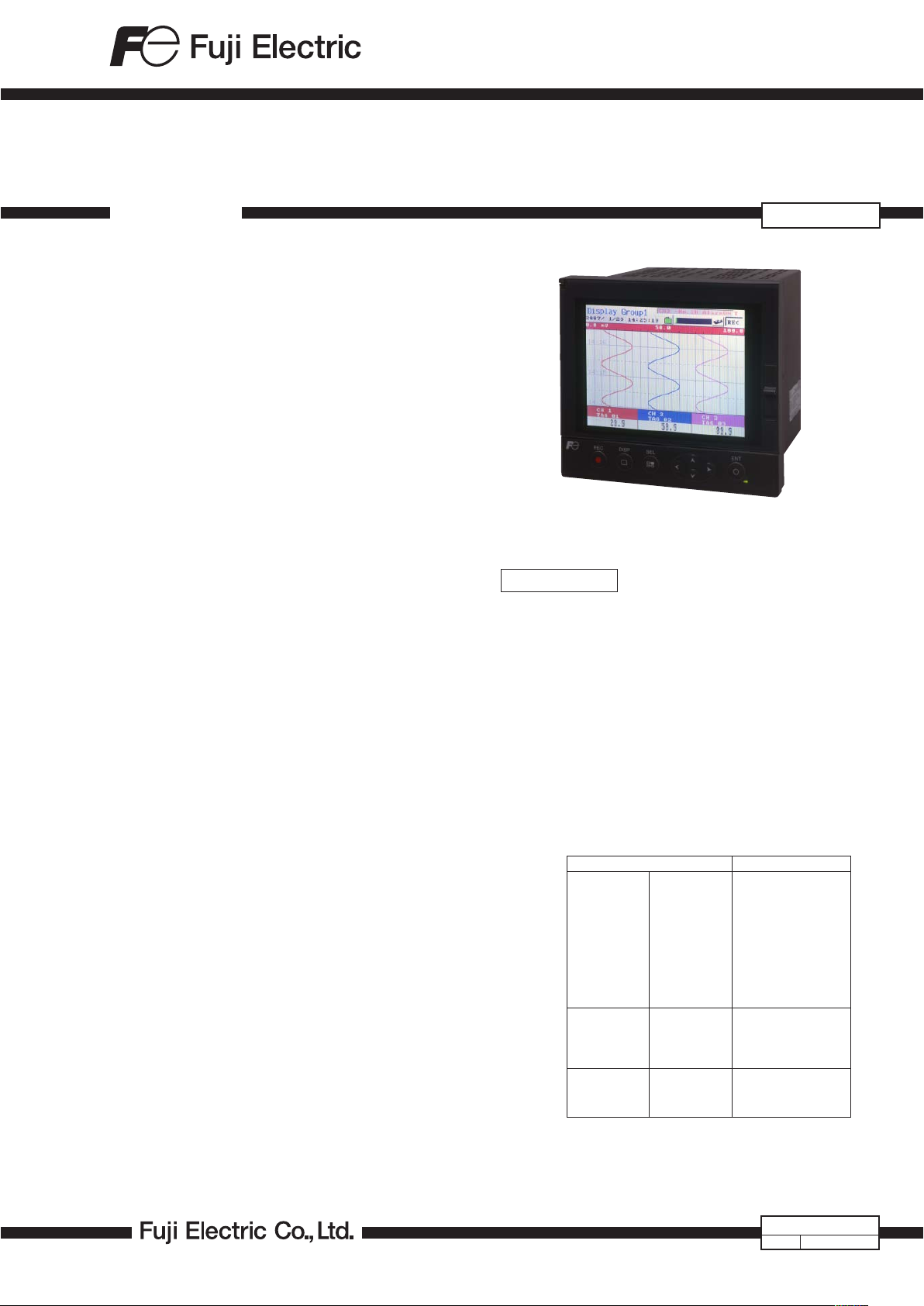
PAPERLESS RECORDER
DATA SHEET
This is a paperless recorder that displays measured data
on the LCD in real time and stores data in CompactFlash.
The type of input such as thermocouple, resistance bulb,
D.C. voltage (current), etc. can be arbitrarily set to 6 channels at the maximum.
The data stored in CompactFlash can be regenerated on
the screen, and the use of supplied support software allows
the data to be regenerated on a PC screen.
The data recorded in ASCII format can be directly read in
a spreadsheet such as Excel, which facilitates the processing on a PC. (The data recorded in binary format cannot be
read in.)
FEATURES
1. Large capacity storage by CompactFlash
Measured data is periodically stored in CompactFlash.
Large storage capacity of up to 512MB allows display files
for approximately 4 years to be recorded continuously at
the display refresh cycle of 30 seconds (in the case of
ASCII data format, 6 channels).
2. Quick search and display of past data
Data stored in CompactFlash can be displayed in succession by scrolling the screen.
3. Various display capability
Depending on the object of measurement, the most
suitable display format can be selected from a variety of
formats including bar graph display, trend display, digital
display, etc.
4. PC support software supplied as standard
Loader software that enables easy display and change of
set data and data viewer software that regenerates the
data stored in CompactFlash are supplied as standard.
5. Compact size
160 (W) × 144 (H) × 185 (D) mm (Panel mounting), 1.5kg
compact size
6. 6-point recording (Option)
12 types of thermocouples, 5 types of resistance bulbs
and DC voltage/current input can be recorded up to 6
points.
7. Screen saver function
If the non-operation exceeds the setting value of parameter, “LCD lights-out time”, recorder turns off the
backlight.
Setting range of this parameter is 0 to 60 minutes. If the
setting value is "0", this function doesn’t work, so the
backlight remains on during power on.
Screen saver function makes the life of backlight expand
and power consumption reduce.
8. Ethernet function (Option)
FTP, Web server, e-mail and MODBUS-TCP are available
using 10Base-T.
PHF-2
SPECIFICATIONS
Input system
Number of input points:
3 points or 6 points (Can be selected at
the time of purchase)
Input circuit: Input mutual isolation
Resistance bulb measured current:
about 1 mA
Measuring cycles:
3 or 6 points….100ms cycles
Recording cycle: 1 sec to 12 hours
Input types: Thermocouple, resistance bulb, DC volt-
age, and DC current (Shunt resistors are
fitted in input terminals).
Note) Order a shunt resistor (type:
PHZP0101) separately.
Measuring range
Thermocouple B
Resistance bulb JPt100
DC voltage 50mV
Note) B, R, S, K, E, J, T : JIS C 1602, DIN IEC 584-1
N : NICOSIL-NISIL (IEC 584)
W : 5%Re-26%Re · W (Hoskins Mfg. Co. USA)
L : Fe-Cu · Ni (DIN 43710)
U : Cu-Cu · Ni (DIN 43710)
PN: Platinum
JPt100 : JIS C 1604 Pt100, Pt50 : JIS C 1604, DIN IEC 751
Input types Reference range
R
S
K
E
J
T
N
W
L
U
PN
Pt100
Ni100
Pt50
Cu50
500mV
1-5V
0-5V
400.0 to 1760.0°C
0.0 to 1760.0°C
0.0 to 1760.0°C
–200.0 to 1370.0°C
–200.0 to 800.0°C
–200.0 to 1100.0°C
–200.0 to 400.0°C
0.0 to 1300.0°C
0.0 to 1760.0°C
–200.0 to 900.0°C
–200.0 to 400.0°C
0.0 to 1300.0°C
–200.0 to 600.0°C
–200.0 to 600.0°C
–60.0 to 180.0°C
–200.0 to 600.0°C
–50.0 to 200.0°C
0.00 to 50.00mV
0.0 to 500.0mV
1.000 to 5.000V
0.000 to 5.000V
1989 (Old JIS Pt 100)
EDS10-81
Jan. 23, 2017Date
Page 2

PHF-2
Selection of input types:
By key operation on the front panel. Note
that the same input type (thermocouple,
resistance bulb, voltage) should be selected for channel 4 and 5. Refer to ”Setting method of input types” for details.
Burn-out function:
Equipped in thermocouple and resistance
bulb inputs as standard, and overswings
the recording to 100% side.
Thermocouple burn-out current:
approx. 0.2 µA
Input filter function:
Settable for each channel (primar y delay
filter) Time constants are settable in the
range from 0 to 900 sec.
Scaling function: Possible by DC voltage (current) input
Scaling range: -32767 to 32767
Decimal position: settable at any point
Unit symbol: settable up to 7 digits and
125+12 types
Subtraction function:
Subtraction between each channel is al-
lowed.
Square rooter function:
Square rooter can be performed against
the input value per each channel.
Indication system
Indicator: 5.7” TFT color LCD (320 × 240 dots)
with backlight, no contrast adjustment.
On the LCD, cert ain picture elements
remain lit or extinguished. On account of
the nature inherent to LCD, the brightness
may be non-uniform. But, such are not
troubles.
Color of indication:
14 colors
Applicable language:
English, French, German, Italian (switchable)
Life of backlight: 50,000 hours (20°C)
(the complete indicator unit should be
replaced when replacing backlight).
Trend display: Direction: vertical and horizontal
Number of channels: 6 channels or 4 channels or 3 channels for the screen (Input:
6 points at the maximum).
Display refreshment cycles:
select from 1 second to 12 hours
No numerical value display. Scale display/
no-display can be selected.
Bar graph display:
Direction: vertical
Number of channels: 6 channels or 4 channels or 3 channels for the screen (Input:
6 points at the maximum).
Display refreshment cycles: 1 second.
Digital display: Number of channels: 6 channels or 4 chan-
nels or for the screen (Input: 6 points at
the maximum).
Display refreshment cycles: 1 second.
Event summary display:
Alarm summary and message summary
can be displayed.
Ethernet log display:
E-mail sending, FTP server log in/off and
MODBUS TCP/IP communication start/
stop can be displayed.
Parameter display/set:
Already-set Data Display and Set Change
Display screen
TAG indication: Number. of characters to be displayed:
Up to 8 characters at 6 channels on one
screen or up to 16 (= 8 × 2) characters
at 4 channels on one screen.
Characters to be displayed:
Alphanumerical characters
Tag, unit and channel number display:
It depends on the screen. See below
table.
Screen
Trend
Bar graph
Digital
x: only 1 item can be displayed.
+: only 2 items can be displayed.
Number of channel
on one screen
4 or less
more than 5
4 or less
more than 5
TAG1 TAG2 unit
+
x
+
x
Items
+
+
x
+
+
all items are displaed
x
ch number
+
x
+
x
Historical trend display:
The past data can be displayed from the
Compact Flash or internal memory. The
past data file can be read and displayed
with scroll display function or jump the
cursor to the position which you entered
date and time. Scale display/no-display
can be selected.
Number of screen groups:
1 group (Up to 6 channels per 1 group
can be registered.)
Keyboard
No. of Keys: 8
Function: Use to select various screens and set
various parameters.
Recording function
External memory media:
Compact Flash card
(Format as FAT32, FAT16 or FAT, or recorder can’t read and write.)
Recording capacity:
2GB maximum (compact flash). Limiting
the recordin g fi le to 64MB is recommended (for 112 hours if display refresh
cycle is 1 second. See Table 1 (p. 6).)
(When the size of the recording file comes
to be 256MB or more, a new file is created
automatically and recording is maintained.)
* Please change the compact flash every
six month to prevent the data losing.
Recording method:
Turning ON the REC key allows measured
data to be written at fixed cycles.
Recorded as a new file whenever the
recording starts
2
Page 3

Data save cycles:
100V AC
240V AC
About 32VA
About 42VA
Linked to the display refreshment cycles
on the “Trend display” screen. However,
they are autom atically set to about 1
minute if the refreshment cycles are set
to less than 1 minute.
Trend data: Average, instance or min. and max. mea-
sured values out of measured data that
are sampled at the measuring cycles are
saved.
Event data: Saves alarm data and power ON data
when the power turns off and on during
recording.
Storage capacity :
Approximately 4 years when the display
refresh cycle is 30 seconds (in the case of
6-channel recording in ASCII data format,
and 512MB Compact Flash is used). Refer
to Table 1.
Memory usage: Indicates the memory which has already
used on the screen. When all the memory
is used up, you can stop recording or
delete the oldest recording file to save
the newest data.
Compact flash card form: PHZP2801
(CF card) (If a card other than the above is used,
no operation assurance is ensured.
Meanw hile, as for other CF card s for
which operation check will have been
completed, the results will be posted on
our company's homepage sequentially.
Please refer to this website.)
Data format: Either of ASCII or binary format can be
selected. (Switching cannot be made while
the recording is in progress. In the case
of ASCII format, the data can be directly
read on Excel, etc.)
Note: The data recorded in binary format
cannot be read directly.
Approximately 118 bytes per sample (for
6-channel input in ASCII format) or approximately 28 bytes (for 6-channel input
in binar y format)
Alarm function
No. of settings: Up to 4 alarms for each channel are set-
table.
Type of alarm: High/Low limits
Indication: Status (alarm types) is displayed on digital
display unit when an alarm occurs.
History display on alarm summar y (Alarm
start/cancel time and alarm types)
Hysteresis: Set within the recording range of 0 to 100%
(it is effective only in case of high/low limit
alarm)
Relay output: Number of points; 10
Alarm latch function:
Keeps alarm indication and alarm output
turning on after alarm reset.
ON/OFF operation is performed according
to key setting.
Power supply
Rated power voltage:
100 to 240V AC
Range of operating voltage:
90 to 264V AC
Supply frequency:
50/60Hz (both employable)
Power consumption
Structure
Mounting method:
Panel-mounted (vertical panel)
Thickness of panel:
2 to 26 mm
Materials: PC-ABS for case and bezel
Color: Black
External dimensions:
Panel-mounted: 160 (W) × 144 (H) × 185
(D) mm
Mass: Approx. 1.5 kg (no option)
External terminal board:
Screw terminals (M3 thread)
RJ45 : Ethernet terminal (option)
Normal operating condition
Power voltage: 90 to 264V AC
Supply frequency:
50/60 Hz ±2% (both employable)
Ambient temperature: Panel-mounted
0 to 50°C
(without Ethernet option*
0 to 40°C
(with Ethernet option*
Note) In case of 30°C or more of ambient temperature,
this display might be fogged little bit (This is not
out of order).
Ambient humidity:
20 to 80%RH
Vibration: 10 to 60Hz 0.2m/s
Shock: None
Magnetic field: 400 A/m or less
Signal source resistance:
Thermocouple input …. 1kΩ or less
Resistance bulb input… 10Ω/wire or less
(resistance of each wire of 3-wire system
should be balanced).
Volt ag e input… 0.1% or less of input
resistance
Mounting posture:
Forward tilt 0°, backward tilt within 30°,
horizontal 0°
Warm-up time: One hour or more after power ON
Environmental protection:
IEC IP50 (Front)/20 (Terminal)
Installation category:
II
Pollution degree: 2
Operating altitude:
2000m max.
2
)
2
or less
1
)
*1: In case of the 12th digit of ordering code is ”Y”.
*2: In case of the 12th digit of ordering code is “E”.
3
Page 4

PHF-2
Safety and EMC standard
Safety standard: Based on IEC61010-1
EMC standard: Based on EN61326
Transportation/storage conditions
Temperature: –10 to +60°C
Humidity: 5 to 90%RH, no condensation
Vibration: 10 to 60Hz, 2.45m/s
Shock: 294m/s
2
or lower (packed state)
2
or lower
Reference standard
Accuracy/resolution:
Measuring conditions (23±2°C, 65±10%
RH, power volt age, frequency fluctuation
within ±1%, no external noise, warm-up
time of 1 hour or more, vertical mounting,
standard values of signal source resistance
and wiring resistance... within 1% )
Input types
Thermocouple
Resistance
bulb
DC voltage 50mV
Note 1) Digital indication accuracy is a percentage (%) of the value in the
measuring range on page 1.
Note 2) No error of reference contact compensation of thermocouple is
included.
B
R
S
K
E
J
T
N
W
L
U
PN
JPt100
Pt100
Pt50
Ni100
Cu50
500mV
1
-
5V
0
-
5V
Digital indication
accuracy
± (0.15%+1 digit)
±(0.3%+1 digit)
for the range shown below
Thermocouple B :
400 to 600°C
Thermocouples R and S :
0 to 300C
Thermocouples K, E, J, T,
L and U :
± (0.15%+1 digit)
± (0.5%+1 digit)
± (0.15%+1 digit)
Note 1
-
200 to -100°C
Error of reference contact compensation:
K, E, J, T, N, L, U, PN: ±0.5°C
R, S, B, W: ±1.0°C
(when measured at 0°C or more)
Max. input voltage:
Thermocouple, resistance bulb, DC voltage: ±10V DC (continuous)
Input resistance: Thermocouple, DC voltage:
About 1MΩ
Digital indication
resolution
0.1°C
0.1°C
10µV
100µV
1mV
1mV
Withstand voltage:
Power terminal – ground: 2000V AC, 1 min
Input terminal – ground: 500V AC, 1 min
Alarm terminal – ground: 2000V AC, 1 min
Alarm terminal – alarm terminal:
750V AC, 1 min
Communication terminal – ground:
500V AC, 1 min
Effect on operation
Effect of power supply fluctuation conditions:
For the fluctuation in the range from 90
to 264V AC (frequency: 50/60Hz)
Reading change (100V AC base): ±(0.2%+1
digit) or lower.
For the fluctuation in the range from 47
to 63Hz (power voltage: 100V AC)
Reading change (50Hz base): ±(0.2%+1
digit) or lower.
Effect of input signal resistance:
Thermocouple input: (0.5µV/Ω)+1 digit
or less
DC voltage: Fluctuation for resistance
value equival ent to 0.1% of the input
resistance: ±(0.2%+1 digit) or lower.
Resistance bulb (for wiring resistance of
10Ω for 1 line (the same for 3 lines))
Reading change: ±(0.2%+1 digit) or lower.
Effect of ambient temperature:
Reading change: ±(0.3%+1 digit)/10°C
or lower.
Effect of Mounting position:
For the backward 30° slant
Reading change: ±(0.2%+1 digit) or lower.
Effect of vibration:
When sine wave of 10 to 60Hz with the
acceleration of 0.2m/s
direction for 2 hours.
Reading change: ±(0.2%+1 digit) or lower.
Effect of external noise:
Normal mode noise (50, 60Hz±0.1Hz)
…
20dB or more
Common mode noise (50, 60Hz±0.1Hz)
…
120dB or more
(Th ermocouple input: minus te rminalground)
(Resistance bulb input: b Line-ground)
2
is applied in each
Others
Clock: With calendar function (Christian era)
Accuracy: ±100ppm or less (monthly
error: about 4 minutes)
However, time error at ambient temperature 23±2°C and power ON/OFF is
not included.
Memory backup: Parameters are saved to the internal non-
volatile flash memory.
The clock and totalized data are backed
up with built-in lithium battery.
Insulation resistance:
100 MΩ or more (when measured between each terminal and ground by using
a 500V DC megger)
4
Additional function (option)
■ Alarm relay output/DI (11th digit of code symbols: “1”)
A card with 10-point relay output and 5-point DI input
can be mounted.
Terminal structure:
M3 screw terminal
Alarm relay output:
Contact output (SPST:10 points),
Individual channel or common output (OR
output) allowed.
DO1: Conta ct cap aci t y; 150V/3A AC,
30V/3A DC (resistive load)
DO2-10: Contact capacit y; 240/3A AC,
30V/3A DC (resistive load)
Page 5

DI input: No-voltage contact input (5 points)
The following control is allowed by contact input.
(1) Recording start/stop
(2) LCD turns on
(3) E-mail sending
On pulse width: 200msec or longer
Off pulse width: 200msec or longer
Ethernet (Option)
The following can be performed through the Ethernet
function.
Note 1
■ HTTP server (Internet Explorer 6 is compatible)
Measurement display:
Dig it ally displays the measurement of
each channel of the recorder and alarm
occurrence status.
Event summary display:
Displays event summary including alarm
ON/OFF.
Main unit information display:
Disp lays mem ory use condit ion s an d
information on the main unit such as the
battery end warning.
Integrated value display:
Digitally displays the integrated value of
each channel of the recorder.
■ FTP server (Internet Explorer 6 is compatible.)
Note 1
File download: Record files stored in compact flash (CF)
can be downloaded from the browser.
File delete: Record files stored in CF can be deleted
from the browser.
Access authentication:
Authenticates access authority to FTP
server.
■ SMTP (e-mail client)
Transmits e-mails to specified address
under the following conditions.
(1) When an alarm turns on or off
(2) When DI is set to ON or OFF
(3) When an error occurs to the main unit
(such as low batter y or no memory
space)
(4) At specified intervals
■ MODBUS TC/IP
Data read: Settings can be read through MODBUS
TCP/IP communication.
Data write: Settings can be written through MODBUS
TCP/IP communication.
Note1: Neither Netscape nor Mozilla Firefox
is available.
Support software
The following software is provided as standard.
• PC/AT-compatible machine
• Operation on PC98-series machines by NEC is not guar-
anteed.
• Operation on self-made or shop-brand PCs is not guaran-
teed.
■ Loader software for PC
Major function: Performs various parameter setting/change
of the main unit
O/S: Windows 2000/XP, Windows 7 (Home
Premium, Professional (Not applicable for
64 bit version))
Required memory:
64MB or larger
Disk drive: Windows 2000/XP/7-capable CD-ROM drive
Hard disk capacity:
Free capacity of 30MB or larger required
Printer: Windows 2000/XP/7-capable printer and
printer driver
Note) PC loader communication cable (type
PHZP1801) is separately required.
■ Data viewer software
Major function: Regenerates the past trend record on the
PC from the data in the Compact Flash.
Provided with historical trend display and
event display functions.
O/S: Windows 2000/XP, Windows 7 (Home
Premium, Professional)
Required memory:
64MB or larger
Disk drive: Windows 2000/XP/7-complaint CD-ROM
drive
Hard disk drive: Fr ee capa city of 30MB or la rger re -
quired
Printer: Windows 2000/XP/7-capable printer and
printer driver
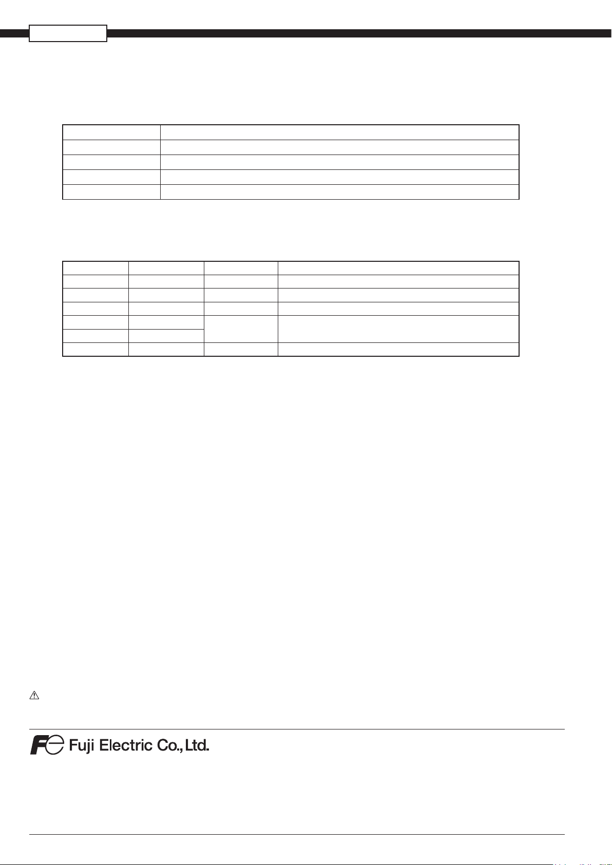
Standard functions
Function
Record range
voluntary setting
Input type setting
Skip function
Trend display
TAG name display
Screen name
display
Unit creation
Scaling function
PV shift
Input filter
Burnout function
Historical
trend display
Recording range can be set by channel.
Input can be set by channel.
(Key operation on the front face)
The same input type is selected for channel 4 and 5.
See “SELECTING INPUT TYPE” on the last page.
Skips arbitrary channel display/recording.
Time display: Time is displayed at the top of the
trend display screen.
Alarm display: On occurrence of an alarm and the
restoration, alarm is displayed in the
alarm display field.
The Compact Flash usage is displayed at the top of
the bargraph.
By channel, Maximum of 8 characters.
Displays the screen name (maximum of 16
characters).
Industrial units can be arbitrarily created, Maximum
of 7 digits, 12 types.
Arbitrary scaling is allowed in the case of DC
voltage input. Decimal point position can also be
arbitrarily set in the range from -32767 to 32767.
Shift the zero point and slant of the reading.
Prevents sudden fluctuation of input for each
channel (primary delay filter).
Time constant: 0 to 900 seconds.
Displays the break of thermocouple/resistance bulb
input by scaling out to 100% side.
Regenerates and displays the data stored in the
compact flash by scrolling the screen or jump to
time when you entered.
Description
5
Page 6
PHF-2
Display refreshment
cycle
CompactFlash size 64MB
1 sec 10 sec 30 sec 1 min 10 min
Recordable capacity
(about)
159 hours
66 days 199 days 398 days
10.9 years
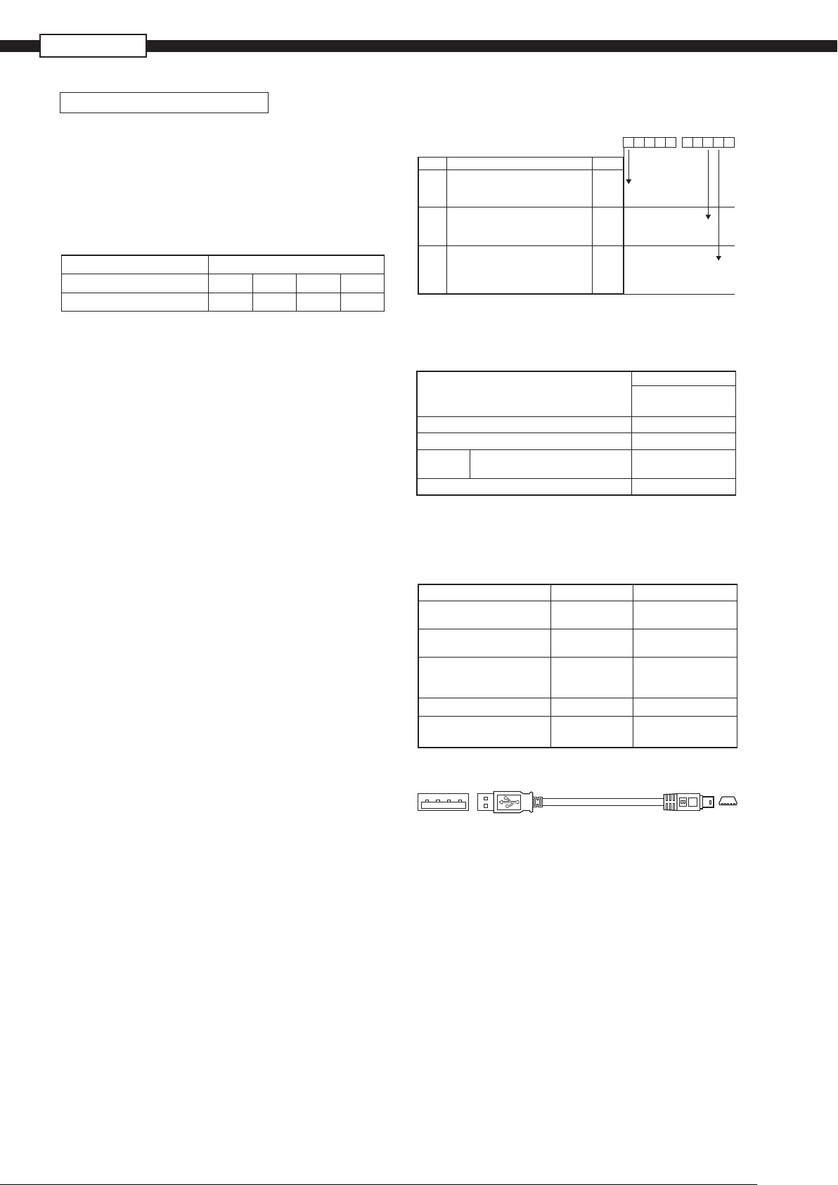
Table 1. Recording capacity
Input point: 6
Data format: ASCII
The recording can be made for the period of time listed in
the tables shown below. When the number of input points
is 3, the period is approximately 1.6 times of those listed
in the table.
In binary format, the period is approximately 4 times as long
as those listed in the table.
CompactFlash size 256MB
Display refreshment cycle
Recordable capacity(about) 26 days 265 days 2.1 years 4.3 years
When Compact Flash is not used, up to 600K bytes of the
recording dat a and the event data can be stored in the
main unit. (In case of 6-channel in Max./Min. recording, approximately 21,000 data can be stored. For 5 hour at the
display refresh cycle of 1 second. The number of the save
data varies depending on the number of the event data.
1 sec 10 sec 30 sec 1 min
ORDERING CODE
Digit Note
4
11
12
Specifications
<Number of input points>
3
6
<
Alarm (relay) output/DI input
Without
With
<
Communication
Without any communication
With Ethernet communication
>
>
STANDARD ACCESSORY
Item
Recorder (PHF)
Panel mounting bracket
CD-ROM PC support software
Noise filter for the power supply
instruction manual
PHF
4 5 6 7 8
5
6
Quantity
mounting
9 10 11 12 13
-
2 1E
Panel
1
2
1
1
V1B1
0
1
Y
E
OPTIONAL ITEMS
Item Code Specification
Shunt resistor for DC
current input
PC loader communication
cable
CD-ROM with Instruction
manual and 2 support
software
PC card adapter PHZP0501 For Compact Flash
Compact Flash PHZP2801-512
* Shape of this cable is shown below
PHZP0101 10Ω ±0.1%
PHZP1801 With USB-A and
PHZP2101
PHZP2801-01G
USB (A) Plug – USB (Mini-B ) Plug
USB miniB * 3m
512MB
1GB
6
Page 7
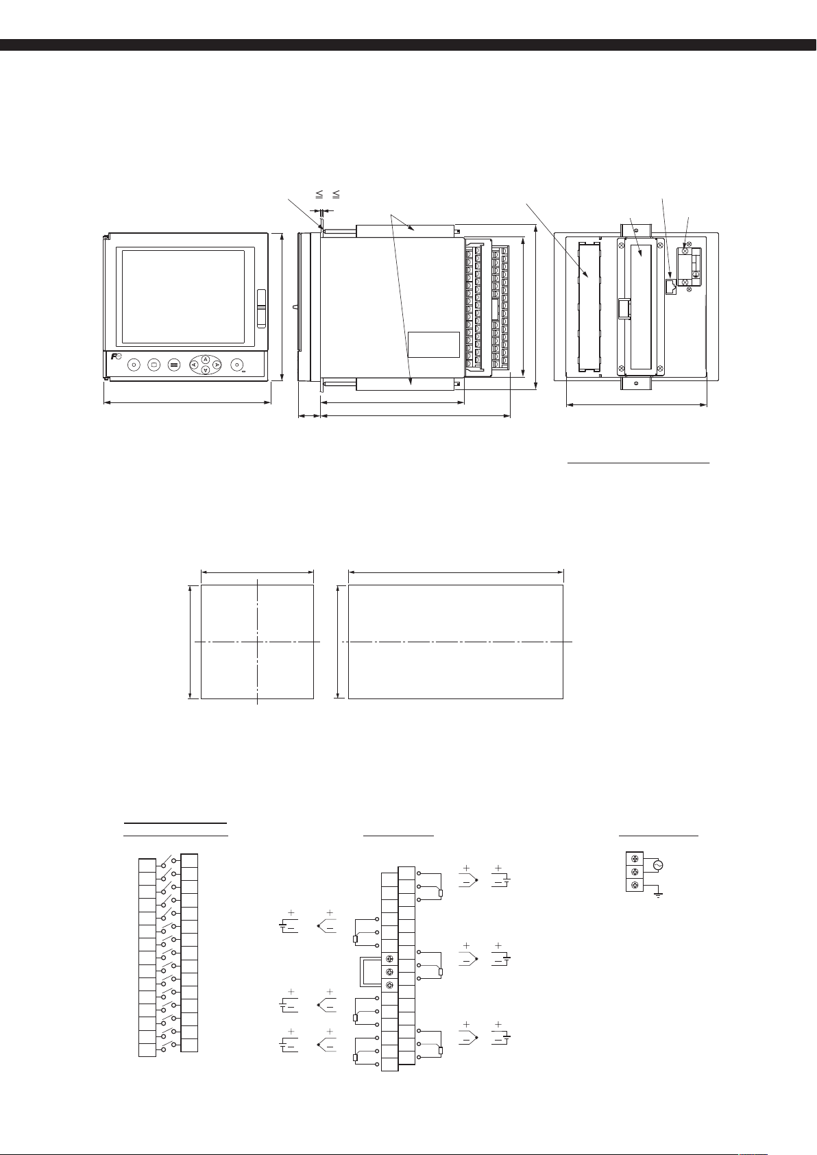
OUTLINE DIAGRAMS (Unit : mm)
PANEL MOUNTING
In the case of 3, 6-point input
Panel
2 T 26
T
Mtg.bracket
Digital input & alarm output
(Option)
Input terminal
Ethernet terminal (Option)
Source terminal
L
N
100〜240VAC
REC DISP SEL
160 140
PANEL CUTOUT
+1.5
143.6
ENT
21.6
185
(Note) When placing the main unit on another instrument
or on the floor, allow a space of 100mm or more between
the unit and instrument or the floor.
Mounting one unit Mounting n unit
0
137
137
+1.5
0
(160 × n-22)
+1.5
0
137
161
136.5
In the case of 3,6-point input
n : Number of units to be mounted
+2
0
Rcj
R‑MODULE
FujiElectric
136.5
Do not use the water proof packing in case of mounting n unit
EXTERNAL CONNECTION DIAGRAMS (M3 screw)
In the case of 3, 6-point input
Alarm (relay) output /
digital Input terminal
211
231
232
233
234
235
236
237
238
239
240
241
242
243
244
245
212
213
214
215
216
217
218
219
220
221
222
223
224
225
DI1
DI2
DI3
DI4
DI5
DO1
DO2
DO3
DO4
DO5
DO6
DO7
DO8
DO9
DO10
Thermo-
Voltage Voltage
couple
CH4
CH5
CH6
(Note1) For current input, connect an optional shunt resistance to a voltage input terminal.
(Note2) Do not use any input terminal which is not needed.
Input terminal
Resistance
bulb
RCJ
41
42
43
51
52
53
61
62
63
Resistance
11
12
13
21
22
23
31
32
33
bulb
Thermo-
couple
CH1
CH2
CH3
Source terminal
AC100 to 240V
50/60Hz
7
Page 8
PHF-2
SELECTING INPUT TYPE
The input types of channel 4 and 5 is the same.
Channel 5 can only be allocated the input type that is the same as channel 4.
The following input types are available.
DetailsInput category
Thermocouple, 50mV
Resistance bulb
500mV
5V
Note) Arbitrary input type can be selected for any channels other than channel 4 and 5 irrespective of the type
allocated to other channels.
Example of channel input type selection
Channel 1 K thermocouple
Channel 2
Channel 3 500mV 500mV
Channel 4
K thermocouple
Channel 5
Channel 6
K, E, J, T, R, S, B, N, W, L, U, and PN thermocouples, 50mV
Pt100, JPt100, Ni100, Pt50, Cu50
500mV
1 to 5V, 0 to 5V
Input category DescriptionInput type
Thermocouple, 50mV
1-5V 5V
50mV
Pt100
Thermocouple,
50mV
Resistance bulb
The input type of the thermocouple and 50mV is the same.
Note 1) Windows 2000/XP, Excel and Internet Explorer are the registered trademarks of Microsoft Corporation in the
U.S.A.
Note 2) Compact Flash is the registered trademark of Sandisk Corporation.
Note 3) Modbus
Note 4) PC98 series are the trade mark or registered trade mark of NEC Corp.
Note 5) Netscape is the trade mark or registered trade mark of Netscape Communication Corp.
Note 6) Mozilla Firefox is the registered trade mark of Mozilla Foundation.
Caution on Safety
*Before using this product, be sure to read its instruction manual.
Global Sales Section
Instrumentation & Sensors Planning Dept.
1, Fuji-machi, Hino-city, Tokyo 191-8502, Japan
http://www.fujielectric.com
Phone: +81-42-514-8930 Fax: +81-42-583-8275
http://www.fujielectric.com/products/instruments/
Information in this catalog is subject to change without notice.
®
is the trade mark or registered trade mark of AEG Schneider Automation International.
Prin te d in Ja pa n
 Loading...