

Page 1
Instruction Manual
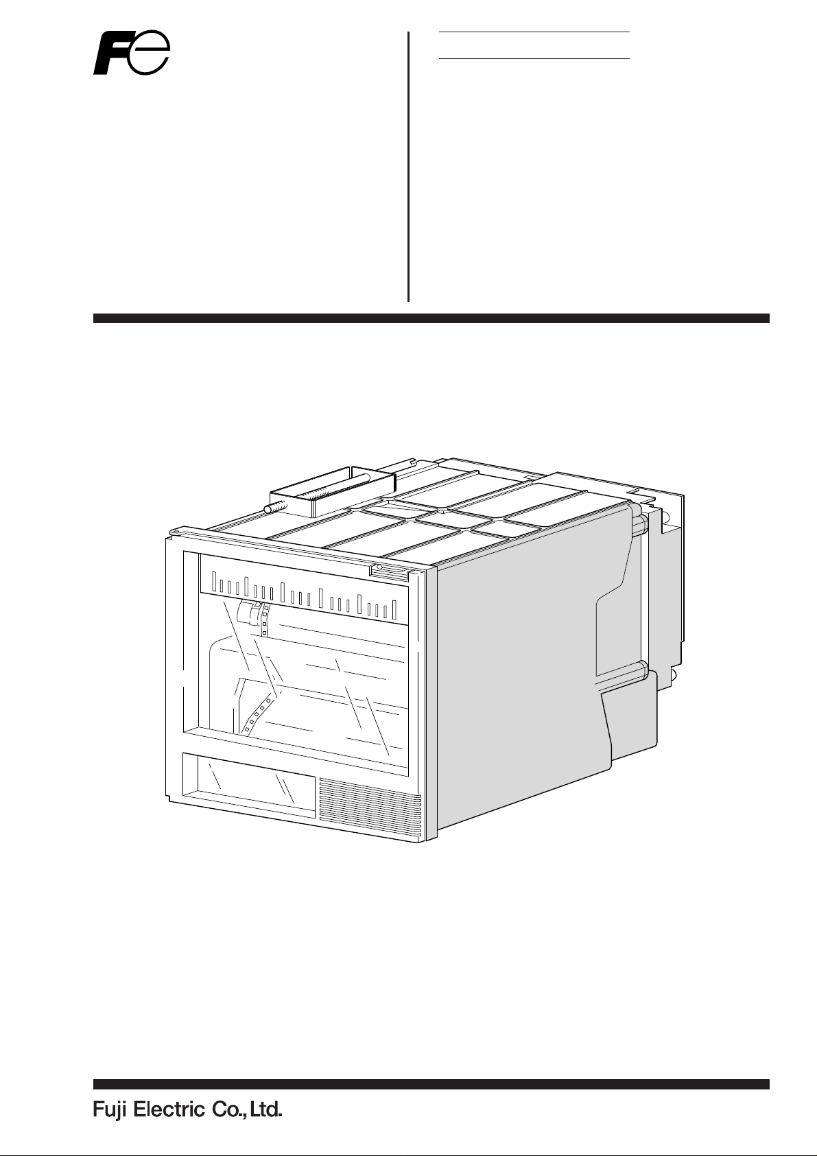
MICROJET RECORDER E
TYPE: PHE–2
INP-TN2PHEVd-E
Page 2

PREFACE
Congratulations on your purchase of Fuji Microjet Recorder (Type: PHE)
• Read this instruction manual carefully to ensure correct installation, operation and preparation.
Incorrect handling may lead to accidnt or injury.
• Failure to comply with the instructions contained in this manual may reduce the safety of the instrument.
• Specifications of this unit is subject to change without prior notice for improvement.
• Modification of this unit without permission is strictly prohibited.
Fuji will not bear any responsibility for a trouble caused by such a modification.
• This instruction manual should be kept by the person who is actually using the unit.
• After reading the manual, be sure to keep it at a place easy to access.
• This instruction manual should be delivered to the end user without fail.
Manufacturer : Fuji Electric Co., Ltd.
Type : Shown on nameplate of Microjet recorder
Date of manufacture : Shown on nameplate of Microjet recorder
Product nationality : Japan
Request
• It is prohibited to transfer part or all of the manual without Fuji's
permission.
• Description in this manual will be changed without prior notice.
© Fuji Electric Co., Ltd. 1999
Issued in November, 1999
Rev. 1st edition April, 2000
Rev. 2nd edition April, 2005
Rev. 3rd edition April, 2011
Rev. 4th edition May, 2014
- i -INP-TN2PHEV-E
Page 3
CAUTION ON SAFETY
First of all, read this “Caution on safety” before using the unit.
• The cautionary descriptions listed here contain important information about safety, so they should
always be observed. Those safety precautions are ranked 2 levels, DANGER and CAUTION.
Wrong handling may cause a dangerous situation, in which
DANGER
there is a risk of death or heavy injury.
Wrong handling may invite a dangerous situation, in which
there is a possibility of medium level trouble or slight injury
CAUTION
or only physical damage is predictable.
PROHIBITION
Caution on Installation
DANGER
CAUTION
Items which must not be done are noted.
• This unit is not an explosion-proof type. Do not use it in a place
with explosive gases to prevent explosion, fire or other serious
accident.
• For installation, select a place observing the operating conditions noted in the instruction manual. Installation at an unsuited
place may cause fall, trouble or malfunction.
• The unit must be installed correctly as shown in the instruction
manual. Incorrect installation may cause fall, trouble or malfunction.
• During installation work, keep the inside of the unit free from
entry of cable chips or other foreign objects as it may cause fire,
trouble or malfunction.
This unit is a component device used for instrumentation. It is
CAUTION
- ii - INP-TN2PHEV-E
mounted on a panel or in a rack.
• The unit conforms to EN61010-1 Safety Standards, and is designed for protection class I, overvoltage Category II and pollution degree 2, except the alarm output terminal (overvoltage category I).
• EMC conforms to EN50081-1 (1992) and EN50082-1 (1992),
(both used for housing areas), except that the noise level of the
power terminal is rated for Class A (used for commercial and
industrial areas).
• Input signals and communication interface should be of SELV
(safety separated from hazardous voltage).
Page 4
Caution of Wiring
DANGER
Caution on Maintenance
DANGER
• Wiring work must be performed as specified. If the unit is not
earthed, it would result in electric shocks or malfunction.
• Be sure to connect power source that matches the rating. Connection of incorrect rating of power source may lead to fire.
• Before starting wiring work, be sure to turn OFF the main power
to prevent electric shocks.
• Wiring materials to be used must meet the rating. Use of materials which do not withstand the rating may cause a fire accident.
• When disposing of the recording head, put it in a vinyl bag
and seal it to prevent the diffusion of ink. It should be handled
as an imcombustible object when disposing of it.
• Ink is harmful to human body. Observe the following emer-
gency treatments.
.
When ink gets in eyes, wash out for at least 5 minutes
immediately with much clean water, and ask your doctor
for treatment at once.
.
When ink gets on skin, wash out and clean skins with
soap and water.
.
When ink is breathed in, move to a clean place immediately. If necessary, ask your doctor for treatment at once.
• Do not touch the connector at the rear of the carriage mount-
ing the recording head to avoid the risk of electric shocks.
Caution on Use
DANGER
• If the fault or anomaly of the device may cause serious accident or troubles to other devices, externally install appropriate protective circuit to avoid accidents.
• This device does not have a power switch. The device has a
fuse, but you cannot replace it. Mount a fuse if necessary.
• When fuse is blown out, check and remove the cause of it,
and replace it with new one specified in the instruction manual.
Do not use any other fuse or short it, as it may cause electric
shocks or fire.
- iii -INP-TN2PHEV-E
Page 5
Caution on Use
r
DANGER
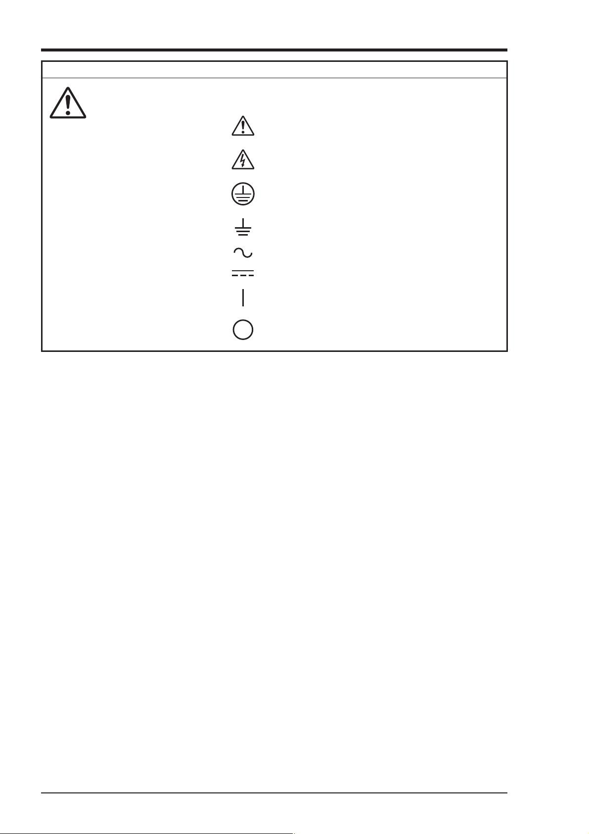
• The following safety symbols are used on PHE SERIES.
Caution (To avoid injury, operator must refe
to the explanation in the manual.)
Be careful of electric shock.
Protective ground terminal
Functional ground terminal (do not use this
terminal as a protective ground terminal)
Alternating current
Direct current
ON (power)
OFF (power)
- iv - INP-TN2PHEV-E
Page 6

CONTENTS
PREFACE .................................................................................................................................. i
CAUTION ON SAFETY..............................................................................................................ii
1. INTRODUCTION ............................................................................................................. 1-1
1.1 Microjet recorder......................................................................................................................1-1
1.2 Product check ...........................................................................................................................1-1
1.3 Check on type and specification............................................................................................... 1-2
2. NAMES AND FUNCTIONS OF PARTS........................................................................... 2-1
3. MOUNTING METHOD..................................................................................................... 3-1
3.1 Mounting location .................................................................................................................... 3-1
3.2 External dimensions and panel cut out dimensions .................................................................3-1
3.3 Method of mounting onto panel ...............................................................................................3-2
4. WIRING ........................................................................................................................... 4-1
4.1 Before wiring............................................................................................................................4-1
4.2 Caution on power source wiring .............................................................................................. 4-1
4.3 Connection to terminals ...........................................................................................................4-2
5. SET-UP ............................................................................................................................ 5-1
5.1 Loading chart paper..................................................................................................................5-1
5.2 Recording head installation (replacement)...............................................................................5-5
6. OPERATION AND ACTIONS .......................................................................................... 6-1
6.1 Before running the equipment:.................................................................................................6-1
6.2 Turning on power and status ....................................................................................................6-2
6.3 Printing the test pattern ............................................................................................................6-2
6.4 Operation in normal mode........................................................................................................6-3
6.5 Displays and print-outs on detection (cancellation) of alarms................................................. 6-4
6.6 Displays and print-outs on occurrent of burnt-out ................................................................... 6-4
6.7 Indication of over-range, under-range display and abnormal input display.............................6-5
6.8 Display of fault in recording head carriage.............................................................................. 6-5
6.9 Display of skipped parameter...................................................................................................6-5
Chapter 3,4 and chapter 8 should be observed for installation and mainte-
CAUTION
nance of the unit. So, it must be performed by qualified engineers.
- v -INP-TN2PHEV-E
Page 7

7. SETTING AND CHECKING PARAMETERS ................................................................... 7-1
7.1 Setting and Checking ............................................................................................................... 7-1
7.2 Outline of procedure for setting parameters............................................................................. 7-2
7.3 Key lock setting/release ............................................................................................................ 7-3
7.4 Setting the Chart Speed (main chart speed) ............................................................................. 7-4
7.5 How to list ................................................................................................................................ 7-5
7.6 How to print the scale (manually) ............................................................................................ 7-6
7.7 How to set ON/OFF of periodic print-out ................................................................................ 7-7
7.8 How to set ON/OFF of scale print-out ..................................................................................... 7-8
7.9 How to set the input filter ....................................................................................................... 7-10
7.10 How to set the alarm ............................................................................................................... 7-11
7.11 Selecting whether to start recording when turning on........................................................... 7-13
7.12 Setting of date and time.......................................................................................................... 7-14
8. MAINTENANCE - INSPECTION ..................................................................................... 8-1
8.1 Maintenance/inspection items .................................................................................................. 8-1
8.2 Battery replacement procedure................................................................................................. 8-2
9. ADJUSTMENT MODE ..................................................................................................... 9-1
9.1 How to adjust the printing and recording (adjust the backlash) ............................................... 9-1
9.2 How to position the analog trend recording (position the head zero/span) .............................. 9-2
9.3 How to set the PV shift ............................................................................................................. 9-3
9.4 How to set the sub chart speed ................................................................................................. 9-5
9.5 How to set the skip ................................................................................................................... 9-6
9.6 Head selection .......................................................................................................................... 9-7
9.7 How to calibrate measured value (ADJUST) ........................................................................... 9-8
10. TROUBLESHOOTING ................................................................................................. 10-1
11. EXAMPLES OF RECORDING AND PRINTING .......................................................... 11-1
11.1 Periodic print-out and scale print-out ..................................................................................... 11-1
11.2 Digital print-out (Instantaneous values) ................................................................................. 11-2
11.3 Parameter listing..................................................................................................................... 11-2
11.4 Test pattern ............................................................................................................................. 11-3
11.5 Scale print-outs (manual print-outs)....................................................................................... 11-3
11.6 Alarm print-outs ..................................................................................................................... 11-4
11.7 Burn-out print-out .................................................................................................................. 11-4
11.8 Record start mark ................................................................................................................... 11-4
11.9 Chart speed change mark ....................................................................................................... 11-4
12. SPECIFICATION .......................................................................................................... 12-1
APPENDIX 1. MOUNTING OF PHE OPTIONAL UNITS ...................................................... A-1
APPENDIX 2. SYSTEM PARAMETER SETTING ................................................................. B-1
- vi - INP-TN2PHEV-E
Page 8
1. INTRODUCTION
We thank you for purchasing Microjet Recorder PHE.
The instruction manual describes installation, operation, maintenance, etc. of Microjet Recorder. Read
it carefully before use.
1.1 Microjet recorder
① This recorder (100mm wide) is used to record up to 6 points of input signals from a thermocouple,
resistance bulb and DC voltage.
② Analog trend data and digital print data are color recorded clearly and quickly.
③ Analog trend data can be recorded continuously or intermittently (see Item 1.3 “Check on type and
specification”).
④ Besides recording measured values, chart paper feed speed, measurement range, etc. can be printed
as standard functions.
1.2 Product check
Upon receiving the unit, check the appearance and accessories to make sure that they are not damages.
Also, check that the accessories are supplied correctly.
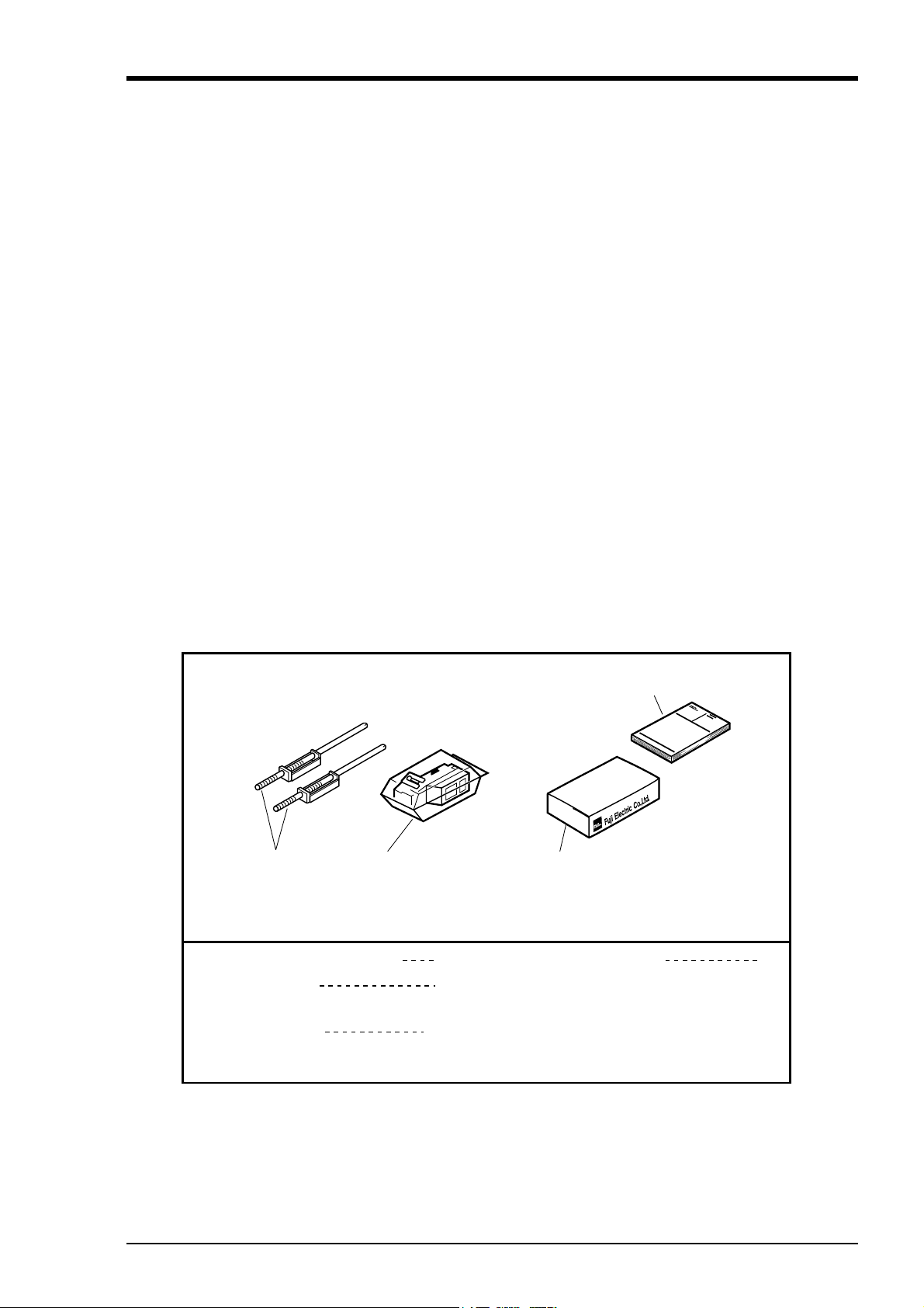
Check on accessories
The unit comes with the accessories shown in Fig. 1-1. Please check that they are all there.
④ Instruction Manual
取
扱
説
明
書
① Panel-mounting
attachments
② Recording head, with
cloth for absorbing ink
(Keep the ink blotting cloth so as not to be lost.)
① Panel-mounting attachments
② Recording head
with cloth for absorbing ink
③ Recording paper
(The standard recording paper No. is
PEX00DL1-5000B)
2
1
1 pack
富
士
電
機
株
式
会
社
③ Recording paper
④ Instruction Manual 1
Fig. 1-1 Accessories
1 - 1INP-TN2PHEV-E
Page 9
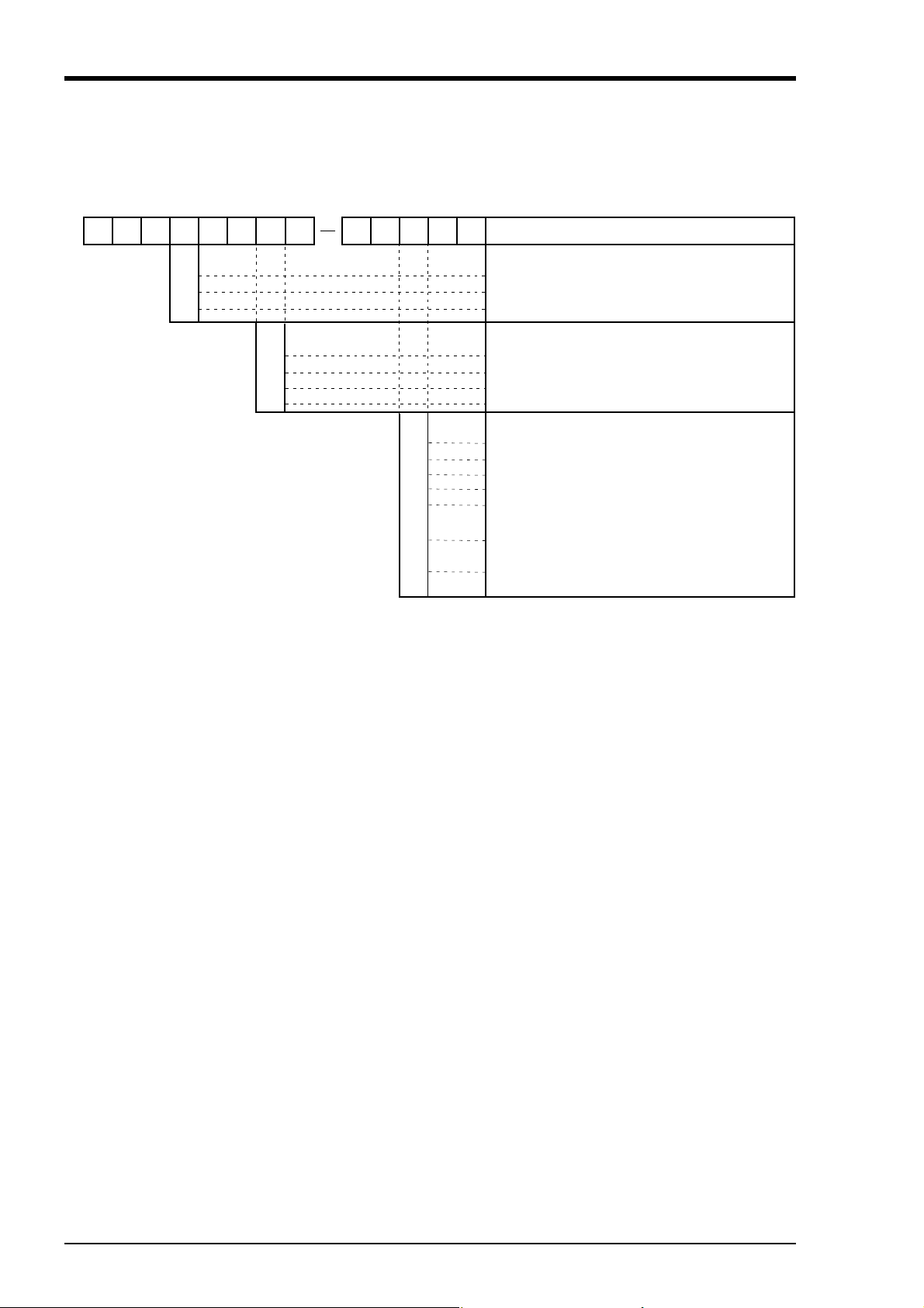
1.3 Check on type and specification
12345678 9
PHE 00 2
1
2
9
1
2
3
4
Input : Universal (Programmable)
Range : Field settable (Programmable)
10 11 12 13
VVV E
0
1
2
3
A
B
C
Recording points
1 continuous recording
2 continuous recording
6 intermittent recording
Power supply · Temperature Unit
100 to 120VAC 50/60Hz °C
200 to 240VAC 50/60Hz °C
100 to 120VAC 50/60Hz °F
200 to 240VAC 50/60Hz °F
Alarm output/external control input (1 point)
Without
2 points alarm output (1 continuous only)
4 points alarm output (2 continuous only)
6 points alarm output (6-intermittent only)
2 points alarm output/External control
4 points alarm output/External control
6 points alarm output/External control
Description
(1 continuous only)
(2 continuous only)
(6-intermittent only)
Note) 1. Initial set before delivery is ;
• Thermocouple K type 0 to 1200°C
2. Shunt resistor (10Ω±0.1%) should be ordered separately
for current input.
Shunt Resistor : Ordering code PHZT1101
Note) Items to specify when ordering except model : PHE □00
1. Code symbols (according to above table)
2. Recording range (scale) and unit in case of DC voltage
and DC current input.
For 2 continuous type, recording range and unit should
be specified for each channel 1 and channel 2.
3. Recording range should be specified with 3 or more
effective figures.
exp. 0 to 100, 0.0 to 10.0, 0.00 to 1.00
Note) Change of kinds of input signal
When changing the kinds of input signal, some adjustments
may become necessary. For adjustments, refer to Appendix, page B-6.
1 - 2 INP-TN2PHEV-E
Page 10
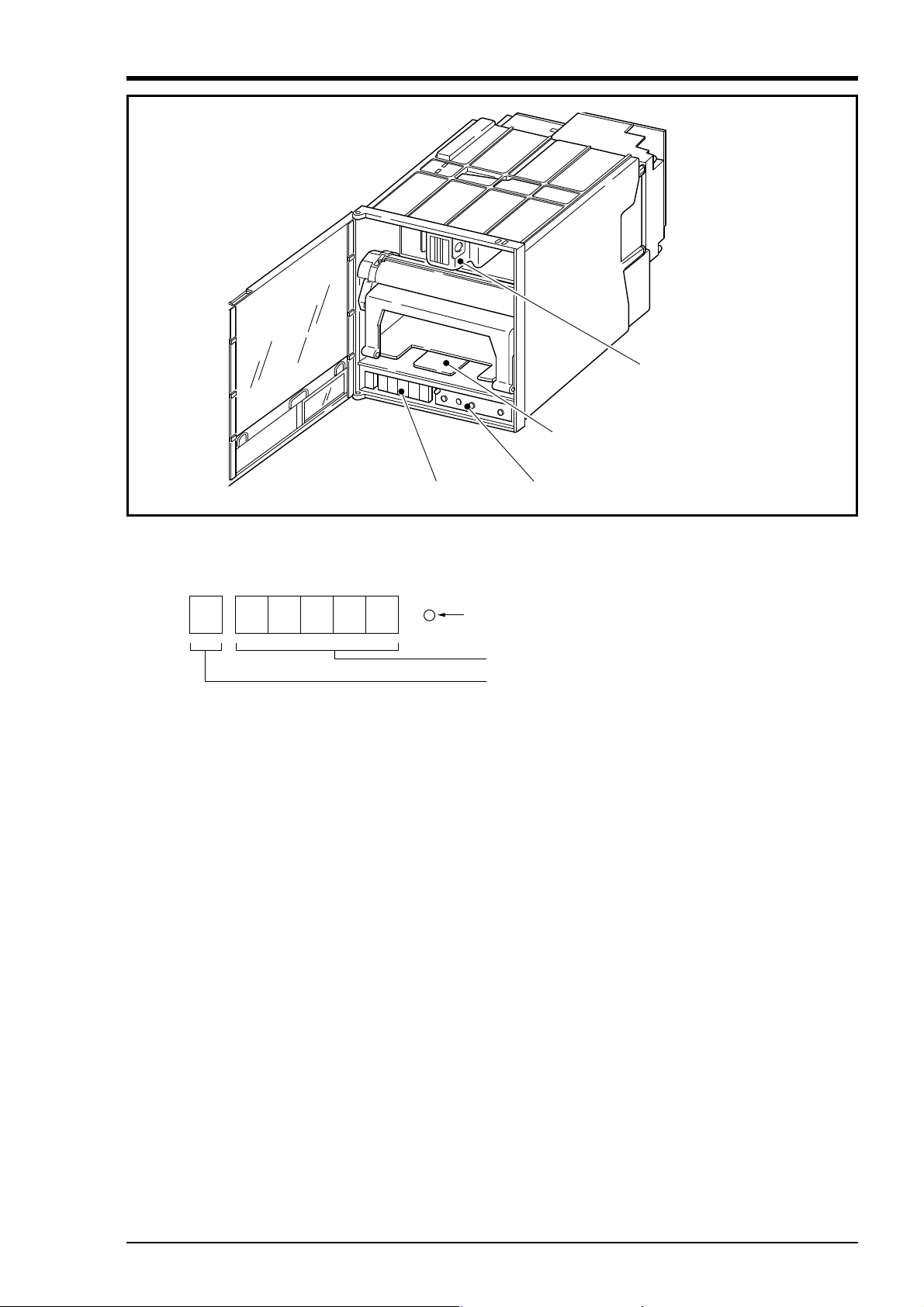
2. NAMES AND FUNCTIONS OF PARTS
Display unit
er
d.
③Paper feed unit drawout lev
②Recording head
①
(1) Display unit
Time, measurement data, set values and comments are displayed.
④Function key board
Under recording Lamp (LED) ON
Measured value and set value are displaye
Channel is displayed.
(2) Recording head
Used for analog trend recording and digital printing. (Recording head is not mounted in the
recorder prior delivery. It should be mounted referring to Item 5.2)
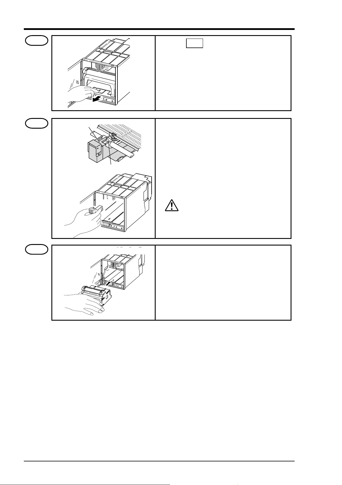
(3) Paper feed unit drawout lever
When setting (replacing) chart papaer, press down the drawout lever and the paper feed unit will be
drawn out. If it is not drawn out automatically, pull out the paper feed unit by hand while pressing
down the lever.
2 - 1INP-TN2PHEV-E
Page 11
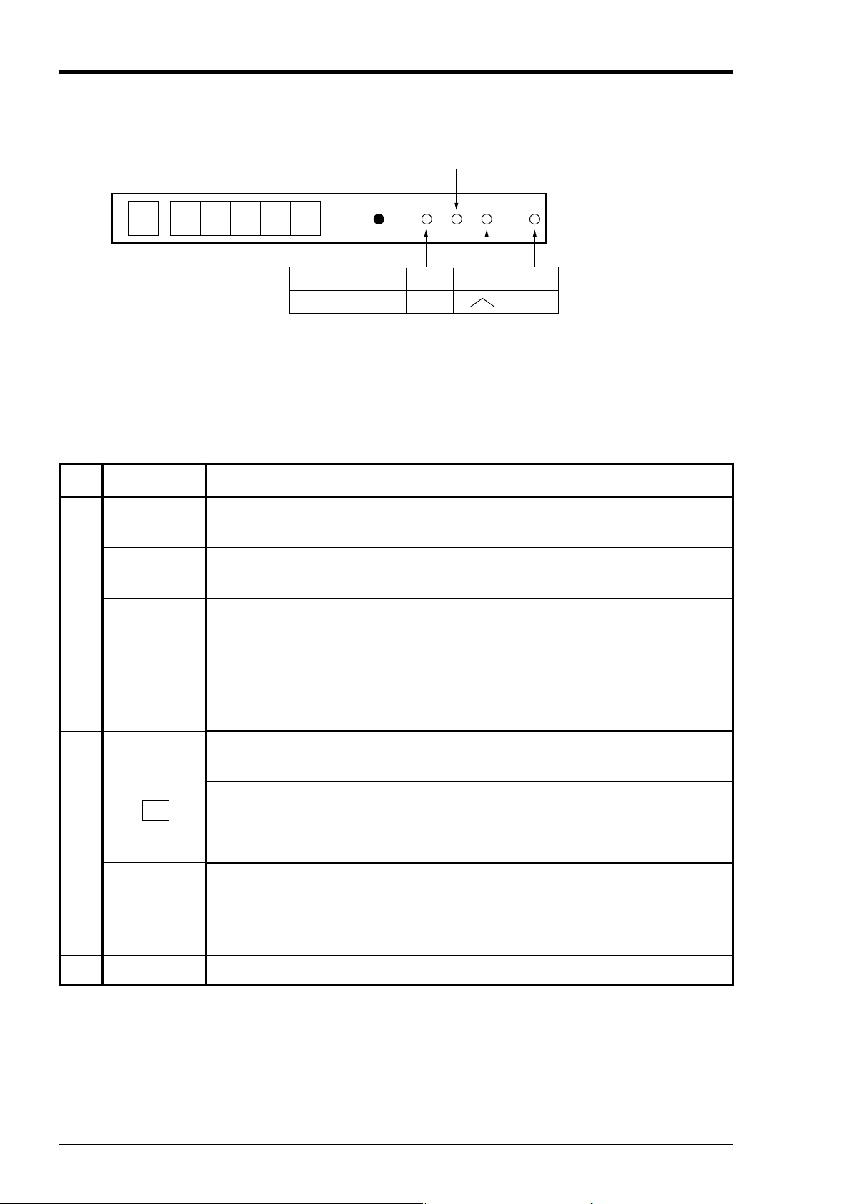
(4) Function key board
Used for setting or confirming parameters and for operating the recorder.
Reset switch
DSPNormal mode
Setting mode
・Normal mode : Measured value or the states of alarm of each channel is displayed. This
mode is started at power ON.
・Setting mode : This mode is used for setting chart speed or alarm.
Name of key
REC
(record)
FEED
(feed)
DSP
(display)
Normal mode
Recording start/stop function key. Recording is started at the first press of the key
and stops at the second press.
Chart paper fast feed key
Feed speed becomes fast by pressing the key for more than 3 seconds.
1. Used for changing display data . The following 2 functions are selected at
each press of the key.
(1) Data of all channels are displayed in order, except for the skip channel.
(2) Display only of the data of specific channels.
SEL ENT
FEED REC
Function
ENT
(entry)
∧
(up)
Setting mode
SEL
(select)
Reset switch
2. Used when shifting from normal mode to setting mode (press the key for more
than 3 seconds)
Used to register set data and to start or stop list printing.
Used to change set data. Chart paper fast feed is effected during list printing.
1. Used to read parameters in order in setting mode. This key can not be used
during list printing.
2. Used when shifting from setting mode to normal mode (press the key for more
than 3 seconds)
Used to reset the recorder (The operation is the same as that at power ON/OFF.)
2 - 2 INP-TN2PHEV-E
Page 12
3. MOUNTING METHOD
P
F
g
P
This unit is designed to be panel mounted.
3.1 Mounting location
Select the following location for mounting the unit.
(1) A place that is not subject to vibration or shock.
(2) A place where there is no corrosive gas.
(3) A place that is subject to little temperature variation and is close to
normal temperature (23°C)
(4) A place that is not struck directly by strong radiant heat.
(5) As humidity affects the ink and recording paper, select a place that
is in the range 45 to 80% RH.
(6) Mount the unit horizontally, with no tilt to the left or right.
(The forward tilt should be 0° but the unit may be inclined 0 to 30°
rearwards.)
(7) A place where you can operate the power switch (or the circuit
breaker) of the device without difficulty.
∠α
α=60to90°
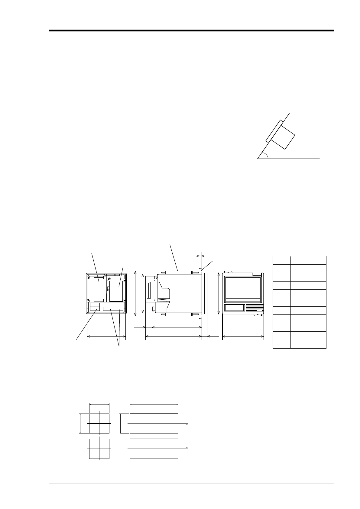
3.2 External dimensions and panel cut out dimensions (unit: mm)
Mounting attachment
Alarm external control terminal (option)
Input terminal (for 6 dot)
161
136.5
22 175
136.4 144
ower supply terminal
Input terminal (for 1, 2 continuous)
197
ANEL CUTOUT
or single unit mounting For left/right tight fit mountin
+1.5
137
0
+1.5
0
137
+1.5
0
137
+1.5
L
0
2≦t≦30
t
Panel
144
19
Number of
units
Mass : Continuous type Approx. 1.3kg
(without alarm terminal)
Approx. 1.5kg
(with alarm terminal)
Intermittent type Approx. 1.5kg
(without alarm terminal)
Approx. 1.7kg
(with alarm terminal)
175Min
Power consumption :
Approx. 13VA (100V AC, without option)
Approx. 15VA (100V AC, with all options)
2
3
4
5
6
7
8
9
10
n
+ 1.5
L
0 (mm)
282
426
570
714
858
1002
1146
1290
1434
(144×n)−6
3 - 1INP-TN2PHEV-E
Page 13
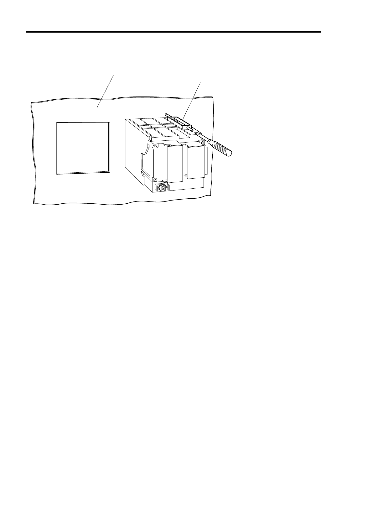
3.3 Method of mounting onto panel
Panel
Screw
• Using the supplied mounting
fixture, tighten the upper and
lower screws until the panel is
fixed.
• The panel to be used should
be more than 2mm thick.
3 - 2 INP-TN2PHEV-E
Page 14
4. WIRING
D
R
C
N
4.1 Before wiring
① For thermocouple input, be sure to use a compensated lead wire.
② Input signal cables should be wired separately as far as possible (30cm or more) from power lines
and high-voltage lines to minimize the effect of inductive noise. Shielded cables should preferably
be used. In this case, the shield braids should be earthed at one point.
Notes
(1) At the completion of wiring of the input terminals, be sure
to close the rear cover to ensure the compensation of reference contact when thermocouple input is used.
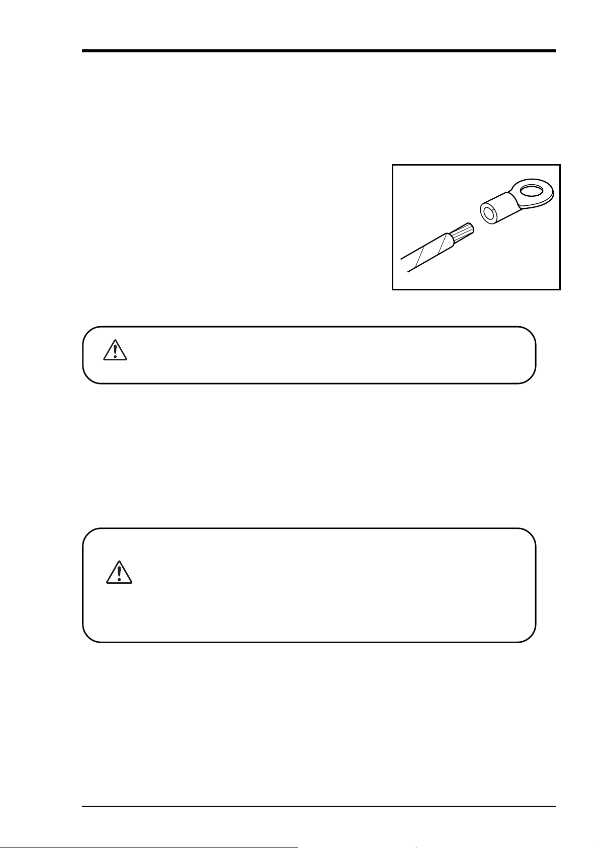
(2) For connection of lead wires to terminals, use of sleeve-
insulated clamping terminals (for M4 screws) is recommended.
4.2 Caution on power source wiring
This device has a power fuse, but it cannot be replaced. Mount an external fuse if
necessary.
AUTIO
① When connecting power cable and earth cable to terminals, be sure to use crimp style terminals
with insulated sleeves (M4 screw).
② For power cable connection, be sure to use 600V vinyl insulated cable or equivalent.
③ A switch (or a circuit-breaker) must be included in the installation.
④ A switch (or a circuit-breaker) must be suitably located and easily reached.
⑤ A switch (or a circuit-breaker) must be marked as the disconnecting device for this equipment.
⑥ Supply wiring shall be prepared by installers in accordance with national regulations.
ANGE
Recommended fuse rating: 250 V AC, T1A or equivalent
・ Before making a wiring work, be sure to turn OFF the main power to prevent
the risk of electric shocks. After wiring, be sure to close the cover.
・ Wiring materials to be used must meet the rating. Use of materials which do
not withstand the rating may cause a fire accident.
・ Wring work must be performed as specified. If the unit is not earthed, it
would result in electric shocks or malfunction.
4 - 1INP-TN2PHEV-E
Page 15
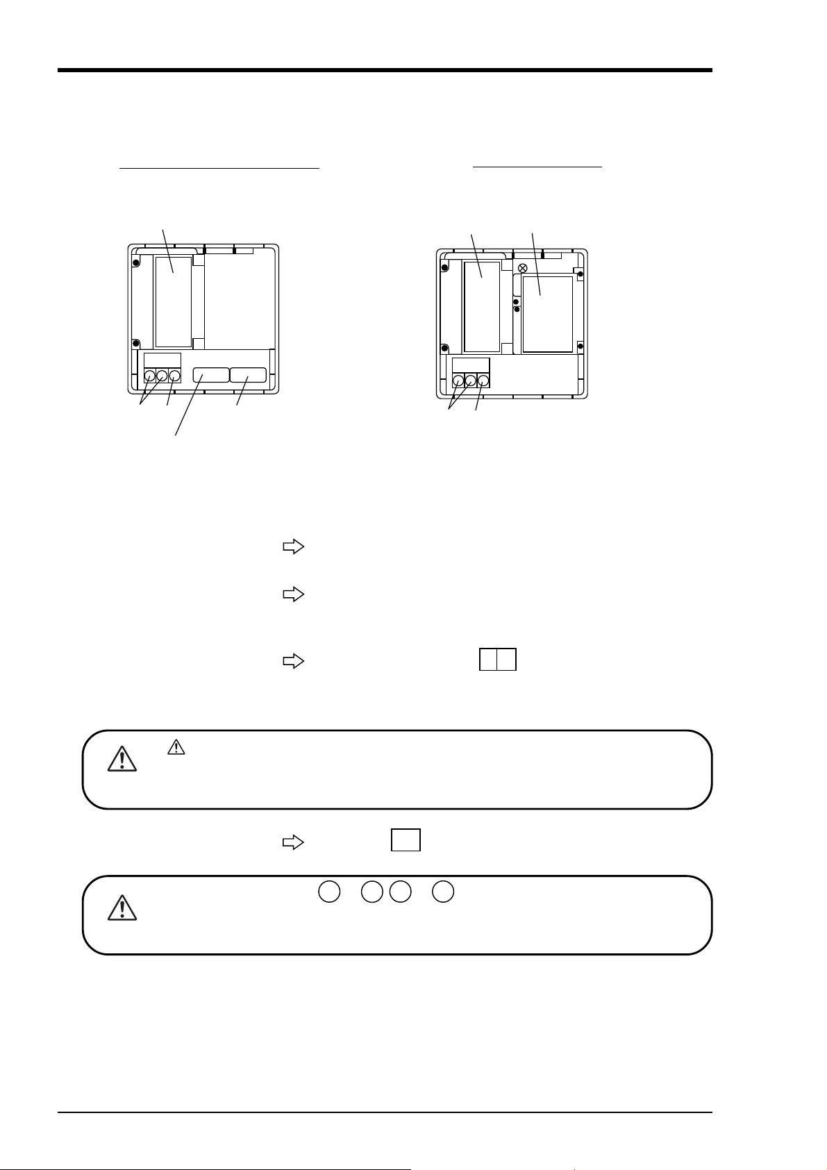
4.3 Connection to terminals
1)
For 2 continuous (channel 2)
②
For 6 dot (channel 1 to 6)
C
N
C
N
1, 2 continuous recording
④③
①
① Input terminal
①For 1, 2 continuous (channel
Connect signal cable for each channel.
6 dot recording_
①
②
④③
② Alarm/external control unit
(option)
③ Power terminal
mark on the power terminal indicates caution for electric shock. The voltage
AUTIO
applied on power terminal after wiring is 100 to 120 V AC or 200 to 240 V. Be sure
to put the cover on the power terminal after wiring to avoid electric shock.
④ Earth terminal
Alarm output terminals ( 11 to 16 , 21 to 26 ) are of overvoltage category I. Other
terminals (input signals, communication interface) are for SELV signals (safety sepa-
AUTIO
rated from hazardous voltage).
Connect the alarm signal output and external control signal input (for alarms 1 to 6, external control).
Connect power cable to L N terminal. Power source to be
connected should be free from noise .
(Code symbol : 100 to 120V AC or 200 to 240 V AC, 50/60 Hz)
Connect to PE terminal (Class-3, less than 10 Ω).
4 - 2 INP-TN2PHEV-E
Page 16
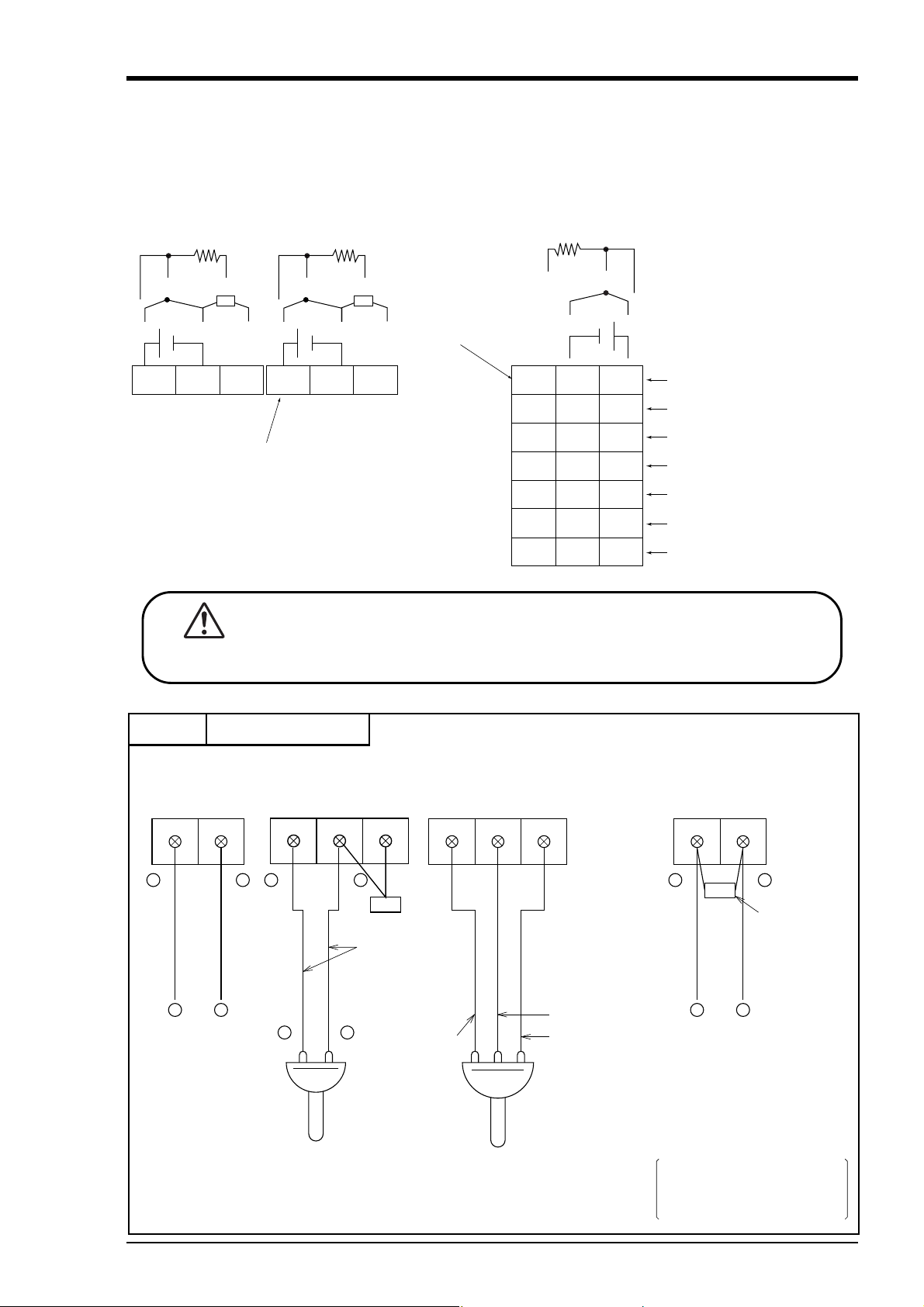
(1) Connection of input terminals
)
+
D
R
① Input terminal No. is determined for each channel.
② Connect input terminals according to the relation between the number of points of input signal and
channel shown in Code Symbols (see Item 1.3).
[For 1, 2 continuous] [For 6 dot]
Bb
RCJ module RCJ module
21 22 23
2 continuous
ANGE
ABbA
− −+
Terminal No.
11 12 13 Input 1
1 continuous
Terminal No.
ABb
131211
232221
333231
434241
535251
636261
737271
Resistance bulb (RTD
+−
Thermocouple (Tc)
DC voltage (V)
Input 2
Input 3
Input 4
Input 5
Input 6
NC
・ Before starting wiring work, be sure to turn OFF the main power to prevent
the risk of electric shocks.
Example
Input terminal wiring
DC voltage input Thermocouple input
11
12
+
11 11
12−13 12 13 11
+
−
RCJ module
Compensating
leads
+
−
DC votlage input
+
−
Thermocouple
Note : Avoid using thermocouple
input with wiring parallel
to other instruments.
<1, 2 continuous>
Resistance bulb input DC current input
bB A
Black (b)
White (B)
Red (A)
+
+
DC current input
Example : 10Ω ±0.1% shunt
Resistance bulb
In this case, ±500mV
input range is available.
12
−
Shunt
resistance
−
resistance is used for
4 to 20mA and 10 to
50mA input.
4 - 3INP-TN2PHEV-E
Page 17
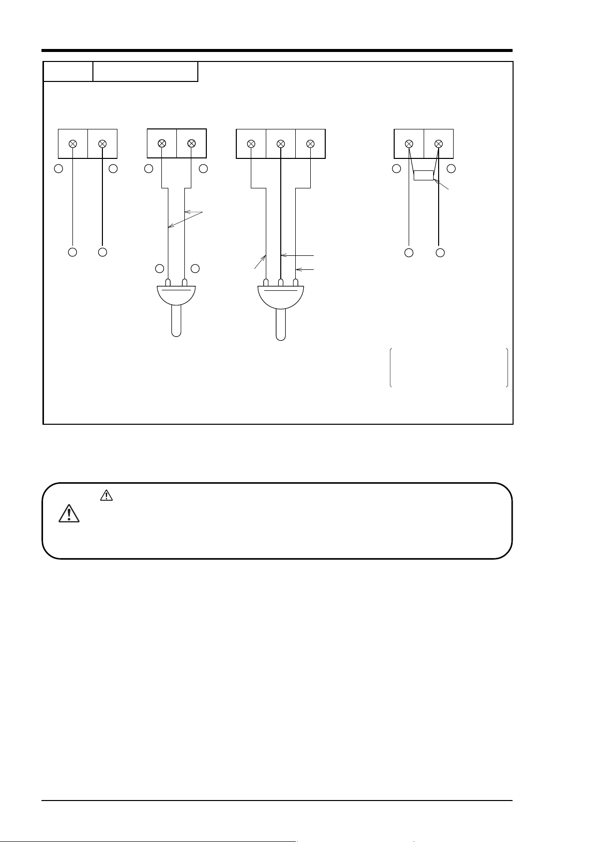
Example
C
N
Input terminal wiring
<6 dot>
DC voltage input Thermocouple input
12+11
−
12 1311 12 11 12 11
−
+
Compensating
leads
+
−
DC votlage input
−
+
Thermocouple
Note : Avoid using thermocouple
input with wiring parallel
to other instruments.
Resistance bulb input DC current input
AB b
Red (A)
White (B)
Black (b)
−
−
DC current input
Example : 10Ω ±0.1% shunt
resistance is used for
Resistance bulb
4 to 20mA and 10 to
50mA input.
Note : The line between channels
is not insulated only at
In this case, ±500mV
input range is available.
input from resistance bulb.
Be sure to use an insulated
type resistance bulb input unit.
+
Shunt
resistance
+
AUTIO
mark on the input terminal indicates caution for electric shock. Put a terminal cover on
after wiring to avoid electric shock. Use the sensor or equipment with basic insulation or
supplementary insulation to connect to the input terminal.
DC voltage/current input signal should be separated from hazardous voltage.
4 - 4 INP-TN2PHEV-E
Page 18
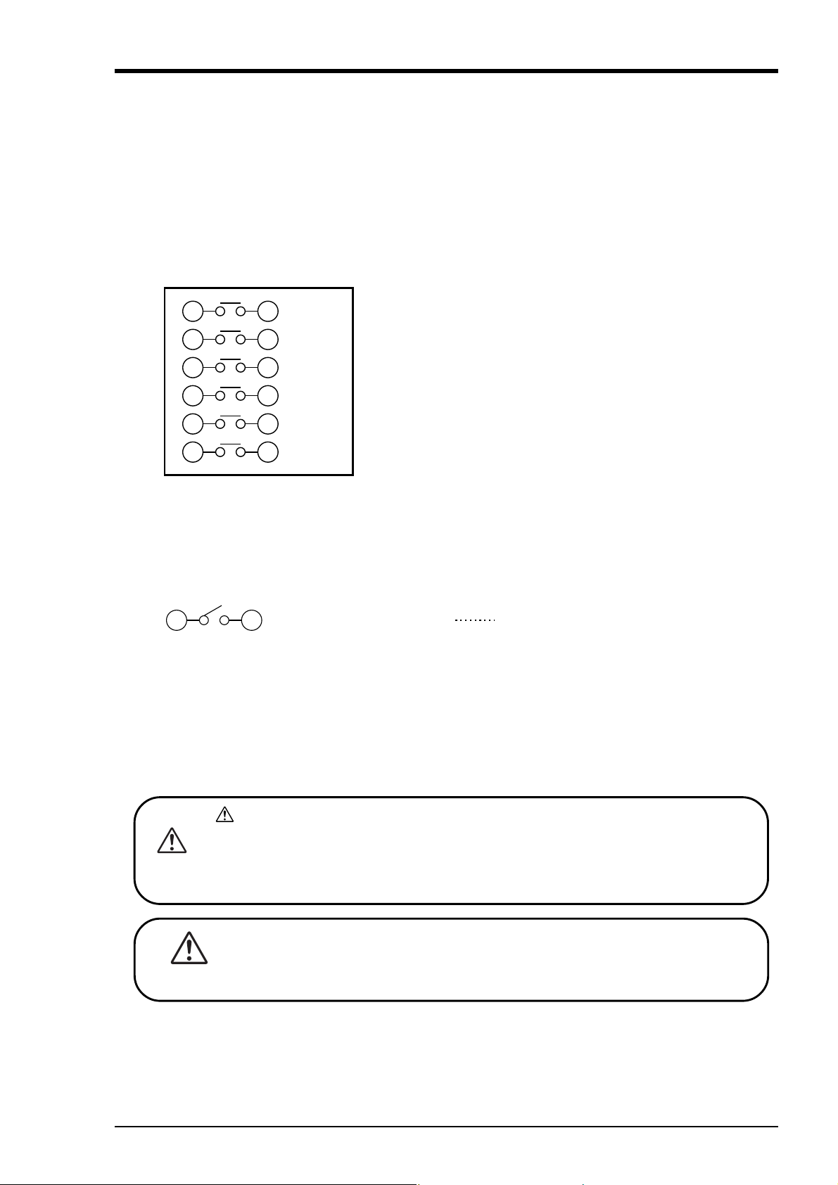
(2) Alarm output/remote control unit (option)
n
D
R
C
N
About alarm outputs :
① Alarm setting (2 points) is provided for each input channel. Alarm output is option and selected
from among 2 points, 4 points and 6 points.
② When an alarm is generated, the relevant terminals are shorted.
1a contact output : Relay contact capacity 240V AC/3A, 30V DC/3A (resistive load)
③ Alarm 1 to 6 corresponds to DO output No. 1 to 6 on the alarm setting panel. For details, refer to
the alarm setting method under Item 7.10.
11 21
Alarm 1
Note : If lamps are used on the outside, insert a resistor to pre-
12 22
13 23
14 24
15 25
16 26
Alarm 2
Alarm 3
Alarm 4
Alarm 5
Alarm 6
vent surge current.
Also, if relays or solenoids are used, insert elements for
contact protection (diodes, surge killers, etc.).
External control unit
① This unit has a function “Chart speed selection” using contact signals from the outside of the
recorder.
② Wiring
17 27 (DI) Chart speed selection Sub-chart speed at short,
and main chart speed at ope
Note 1) The external control unit is not insulated and should be used with a relay connected to the
outside.
External contact capacity : 12V DC/0.05A, 1a contact
Note 2) Recording start/stop operation is selected by setting sub-chart speed to 0 mm/h.
For details, refer to the sub-chart speed under Item 9.4.
mark on the terminal of alarm output/external control unit indicates caution for
electric shock. Be sure to put the terminal cover on after wiring to avoid electric
AUTIO
shock. Use the equipment with basic insulation or supplementary insulation to connect to the terminal of alarm output/external control unit.
・ Before starting wiring work, be sure to turn OFF the main power to prevent
the risk of electric shocks.
ANGE
4 - 5INP-TN2PHEV-E
Page 19

(3) Caution on connection of input signal through barrier
A) Thermocouple input and resistance bulb input.
Perform "Calibration of measured value" with the input connected to the barrier recorder because
the barrier internal resistance is added and causes an error in the measured value.
For the calibration method, refer to Item 9.7.
B) When using Fuji Zener Barrier (PWZ), a power source 100V AC line (100 to 120V AC) should
be used to ensure safe operation of the unit.
4 - 6 INP-TN2PHEV-E
Page 20
5. SET-UP
C
A
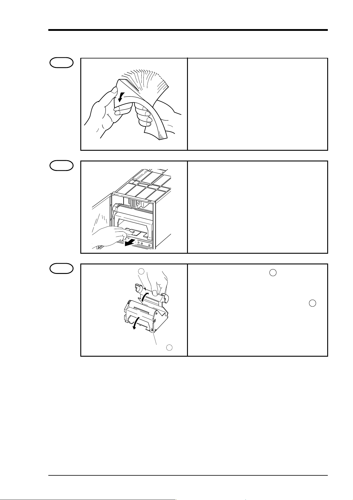
5.1 Loading chart paper
Step 1
Step 2
Prepare chart paper.
Loosen both ends of the chart paper thoroughly to
prevent sheets from being fed together.
Open the front door and press down the paper feed
unit drawout lever.
The paper feed unit will be drawn out.
Step 3
hart paper retainer B
Hold the chart paper retainer B and open it backward.
Also, hold and open the chart paper retainer A .
Chart paper retainer
5 - 1INP-TN2PHEV-E
Page 21
C
r
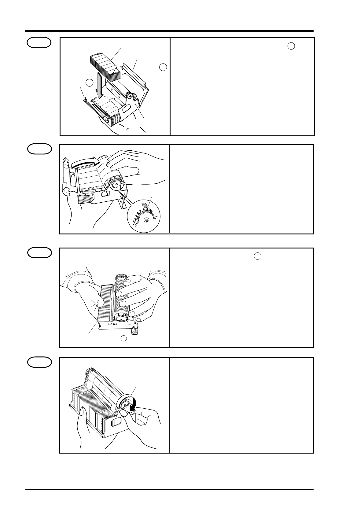
Step 4
hart paper
etainter B
Chart paper
Paper feed unit
Chart paper
retainter A
Set chart paper in the chart paper retainer B as
illustrated.
Step 5
Step 6
Align the perforations of the chart paper with the
pins.
Pin
Close the chart paper retainer B . (The chart paper
is set vertically).
Chart paper retainter B
Step 7
Turn clockwise the gear of the roller unit with hand
and check that the chart paper shifts forward.
Gear
5 - 2 INP-TN2PHEV-E
Page 22
C
r
r
es
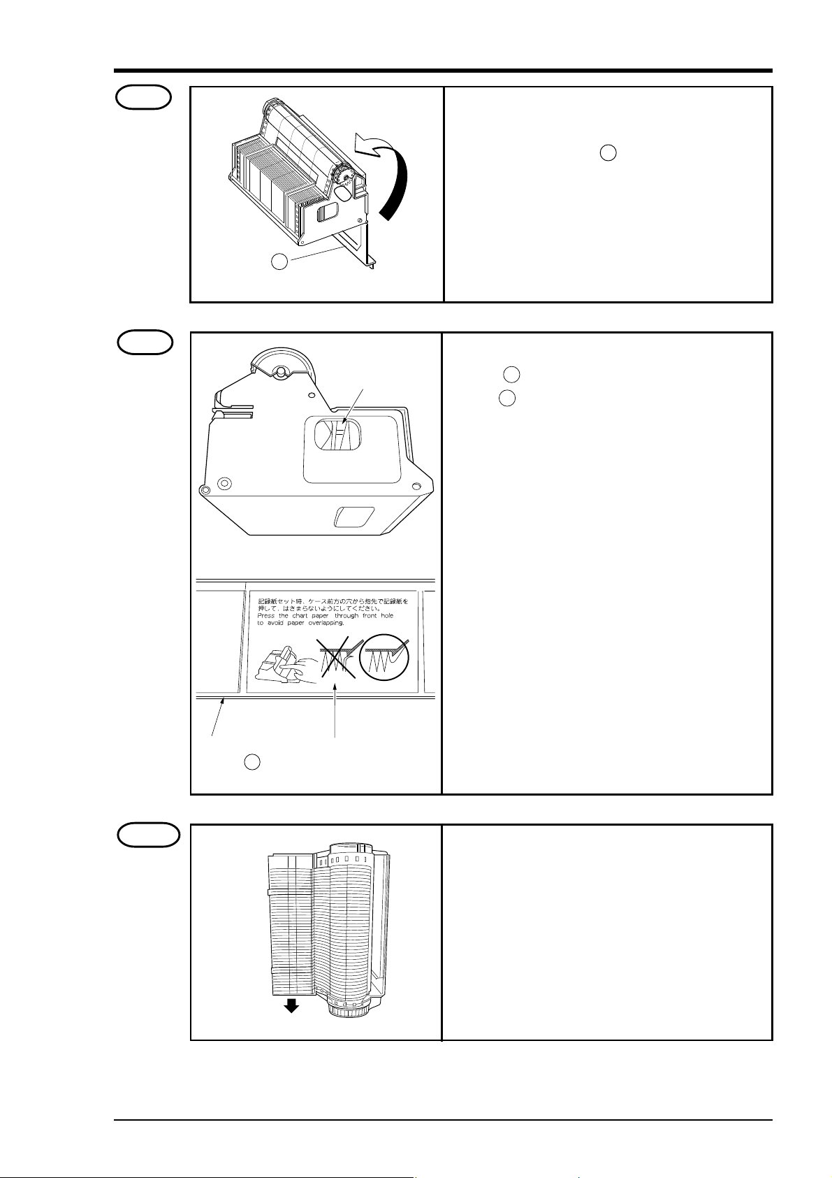
Step 8
Transfer the chart paper that has been forwarded
into the storage of the paper feed unit. Then close
the chart paper retainer A .
hart paper
etainter A
Step 9
Chart paper
retainter B
Check the chart pape
through this hole.
Caution in setting
a chart paper
As shown by the caution display on the chart paper
retainer B , if paper is caught in the chart paper
retainer B , paper jam may result.
As shown by the figure at left, check through the
holes on the left and the right side of the paper feed
unit that the chart paper is not caught in the retainer.
Step 10
Side provided with long hol
The chart paper is provided with long holes and short
holes. Gather the chart paper in the storage to the
side provided with short holes as illustrated on the
left.
Gather the
chart paper
Side provided
with short holes
5 - 3INP-TN2PHEV-E
Page 23
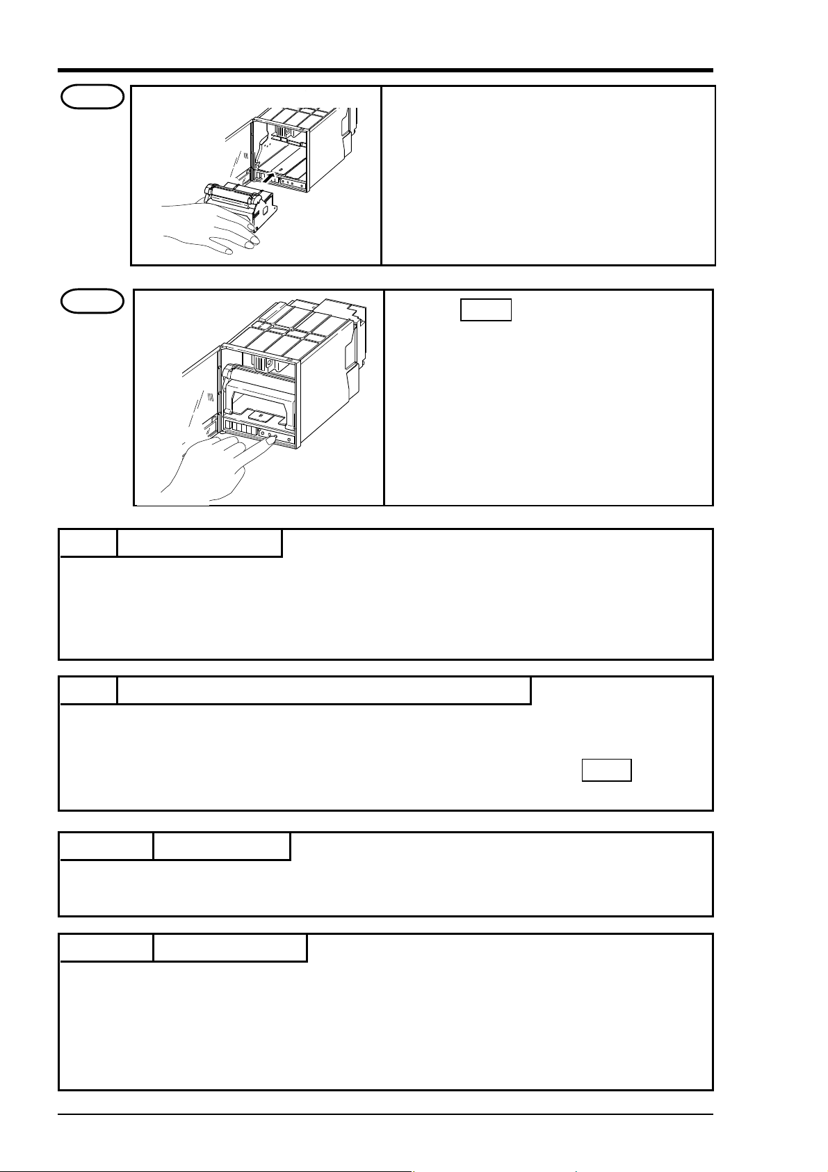
Step 11
Mount the paper feed unit in the recorder. At this
time, check that it is properly locked in position.
Step 12
Press the FEED key and check that the chart
paper is fed out smoothly.
(Feed out about 2 folds of paper.)
<If the paper is not fed out smoothly, go through
the procedure from Step 2 again.>
Note 1 Selection of chart paper
The chart paper greatly affects the quality of the printed recording and it is also related to problems such
as paper jamming, etc.
Please be sure to use the pure-quality chart paper specified us.
Chart paper type: PEX00DL1-5000B (50 equal divisions, no time lines).
Note 2 Use of the recorder after it has been left unused for a long time
If the recorder is left unused for a long time with chart paper still in the main unit, the paper 'packs down'
and if the recorder is used straightway there can be problems of paper jamming, etc.
If you use the equipment after it has been left unused for a long time, first press the FEED key to feed
out 2 to 3 folds of the paper.
Reference 1 Chart paper length
The chart paper is approximately 15m long. This permits about 31 days continuous print-out at a chart
speed of 20mm/h.
Reference 2 Chart paper end mark
The remainder of chart paper is indicated by numerals on the right of paper (unit : 10cm). When it
becomes small, a red band will appear on the right to indicate that the chart paper needs to be replaced
with new one.
(Note) The recorder is not provided with a chart paper end sensor. When chart paper is used out, stop
recording or replace the chart paper with new one.
5 - 4 INP-TN2PHEV-E
Page 24
5.2 Recording head installation (replacement)
S
The recording head is a combination of a head and ink.
When ink is used out or trouble arises with the head, it can easily be replaced.
Use the recording head carefully observing the “Caution” noted in the later paragraph.
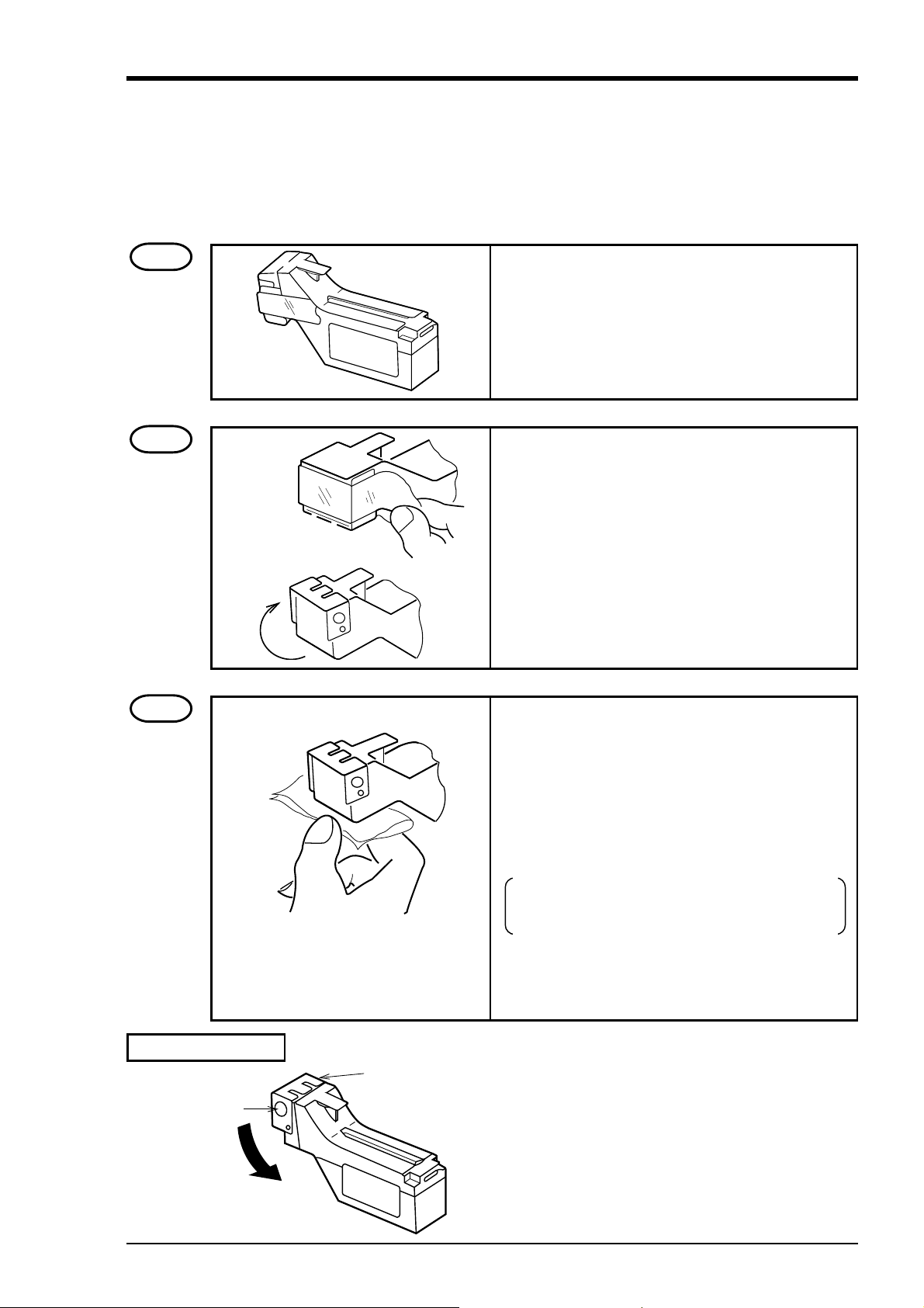
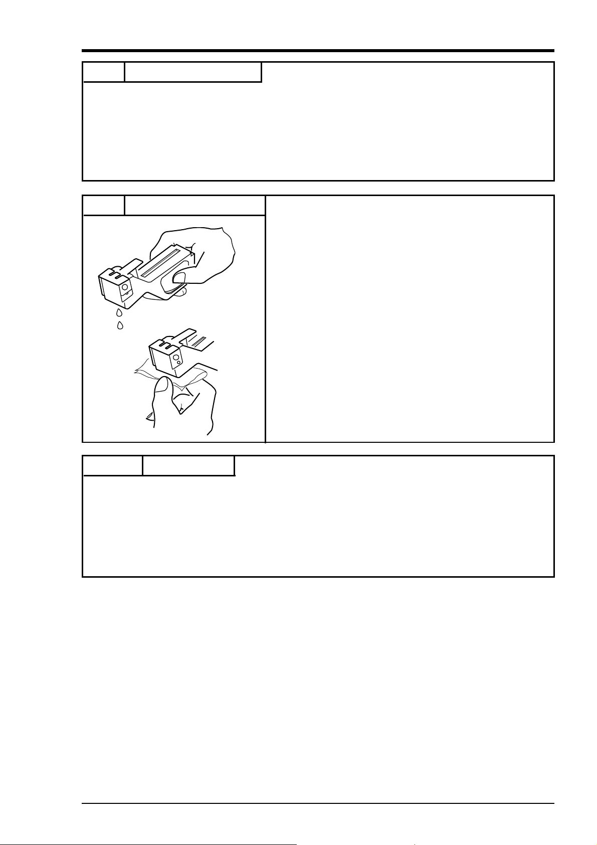
Step 1
Step 2
Get the recording head ready by taking it out of its
aluminium pack.
Tear the tape.
Open the cap by turning it in the direction indicated
by the arrow.
(If the head is not going to be used for a long time,
close the cap back in its original position.)
The cap is integral with the head unit. Turn it about
180° until it stops against the top of the head.
Step 3
How to close the cap
Cap
topper
• Lightly attach the supplied cloth to the nozzle
(ink ejecting side) to such up the ink. For the
standard head, check to make sure that 4-color
ink, blue, red, yellow and black, are soaked into
the cloth (for the 2-color head, 2 colors of ink are
soaked).
First press the cloth against the surface for 2 to
3 second; if the 4 colors ooze out, it is OK.
Note) Do not use any cloth other than the supplied
one. Also, do not rub the nozzle with the
cloth.
• Turn the cap in the direction indicated by the arrow and press it firmly until it is retained by the
stopper.
• Ink may leak out if the cap is not properly in place.
5 - 5INP-TN2PHEV-E
Page 25
Step 4
R
C
N
• Press the REC key. Operate the recorder after it
has been set in recording stop mode.
• Open the front door and press down the paper
feed unit drawout lever.
The paper feed unit will be drawn out.
Step 5
Step 6
ecording head
Nozzle cariage
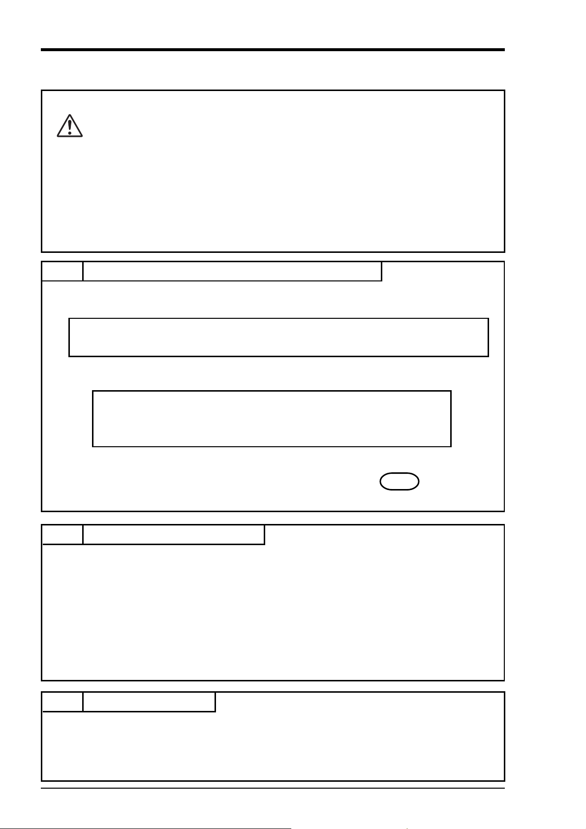
• Hold the recording head horizontally, line it up
with the carriage in the main unit, slide it in
slowly and press it firmly until it does not go in
any further.
• Take care not to bang the nozzle surface of the
head. Also, avoid touching the nozzle surface with
your hand.
Do not touch the connector at the rear
AUTIO
of the carriage to avoid the risk of minor electric shocks.
・Set the paper feed unit in its original position.
The above completes installation of the recording head.
The recording head is a consumable part. When the built-in ink is used out, replace the head with
new one.
It comes in 2 types, one is for the 1, 2 continuous recording (PHZH2002) and another for the 6 dot
recording (PHZH1002). Choose the type of the head according to the recording mode of the recorder.
5 - 6 INP-TN2PHEV-E
Page 26

Recording head replacement
Draw out the recording head in the manner that is opposite to what is described in Step 5 of the
recording head setting procedure, and replace it with a new recording head.
Always carry out the following procedure after replacing a recording head.
(1) Test pattern print-out
Print out a test pattern to check that normal recording is possible. See Section 6.3 for the way of
printing out a test pattern.
(2) Adjustment of analog trend recording positions
Referring to Section 9.2, readjust the zero and span on the recording paper.
5 - 7INP-TN2PHEV-E
Page 27
Precautions in handling recording heads
D
Handling recording heads
• Do not knock or shake recording heads as this can cause faults.
• The inks are not harmful but they are v ery dif ficult to remove if they adhere to the skin or
ANGER
to clothes, so handle heads carefully in order to avoid staining. Also, do not disassemble
them.
• If, by accident, it happens that ink gets into your eyes, wash thoroughly with water as an
emergency measure and then immediately consult a specialist doctor.
• When the recording head is empty of ink, it should be disposed of as a incombustible
object or returned to our office for reuse (recycling).
Note 1 If recording is halted and the recorder is not used for a long time
Carry out the following in order to prevent jamming and drying-up of the ink.
Remove the recording head from the main unit, make absolutely sure the cap is closed properly and store the head in a cool, dark place (average temperature 5 to 30°C).
If the head is left installed in the recorder:
Do not switch off the power to the recorder and do not close the cap.
* Periodically, there is an automatic discharge of ink to prevent drying-up.
Leave the recording paper in place in the recorder.
If it is not possible to keep the power switched on, make sure that the cap is closed.
Draw out the paper feed unit using the recording head setting method Step 4 .
Open the indicator and tighten the cap.
Note 2 At the start of use of a recording head
If you are starting to use a new recording head or if the recorder has been left unused for a long time,
always wipe the head's nozzle surface lightly with the accessory cloth and check that the ink oozes out
properly into the cloth. (See Step 3.)
Also, after normal recording is possible. See Section 6.3 for the way of printing out a test pattern.
When the working environment is 15°C or less, perform print-out of "test pattern" after period of several minutes has elapsed since the recording head was mounted. (The recording head has a built-in
heater.)
Note 3 Storage of recording heads
When they are delivered, recording heads are in aluminium packs.
If you are not going to use a head straight-away, leave it sealed and store it in a cool, dark place with an
average temperature of 5 to 30°C.
5 - 8 INP-TN2PHEV-E
Page 28
Note 4 Shipping of recording head
• Do not ship the unit recording head after the aluminum pack was opened up. If it is necessary to ship
the unit recording head under avoidable circumstances, be sure to close the cap, and ship it as con-
tained in a boxboard in the state where vibration and impack are eased using cushioning materials.
• Always close the cap if you are transporting a head while it is still installed in the recorder main
unit.
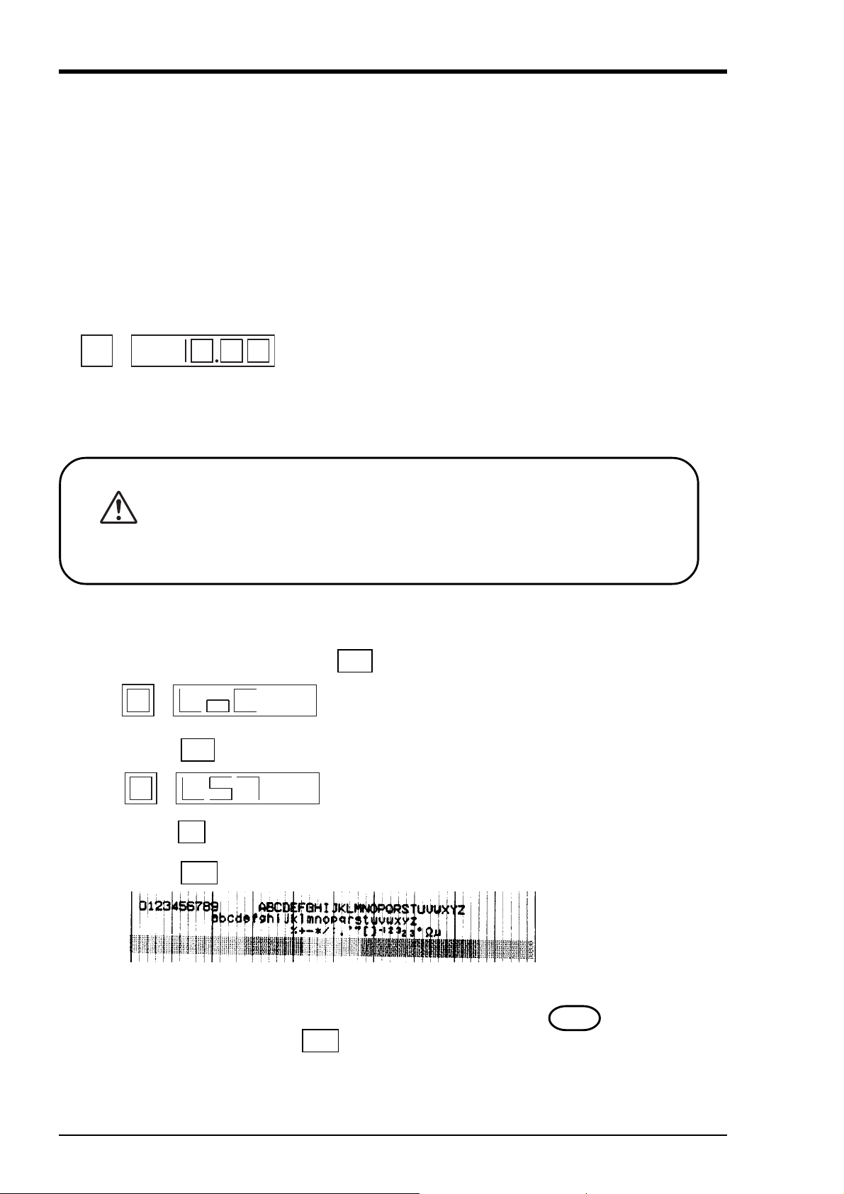
Note 5 If the ink is not sprayed.
①Hold the recording head with turning the nozzle surface
downward and push the side strong till spilling two drops.
②Absorb the standing ink on the nozzle surf ace with the cloth
attached.
③Hold the cloth to the nozzle surface again to find the ink
flowed onto cloth.
When ink does not come out, repeat the above operation
( ① through ③).
* When working environment is 15°C or less, perform
print-out of "record" or "test pattern" after a period or
several minutes has elapsed since the recording head was
mounted. (The recording head has a built-in heater.)
Reference Ink consumption
When recording at 20mm/h of chart speed and a given input, the consumption of ink is as sho wn belo w,
though it depends on operating conditions.
1 continuous recording --------- about 20 months
2 continuous recording --------- about 12 months
6 dot recording ------------------ about 8 months
5 - 9INP-TN2PHEV-E
Page 29

6. OPERATION AND ACTIONS
6.1 Before running the equipment:
Check the following points before starting operation.
1
2
3
Setting the chart paper and recording head
① Setting the chart paper ..................................................................................... See Section 5.1
② Setting the recording head ............................................................................... See Section 5.2
Wiring
① Input terminals .................................................................................................
② Alarm terminals (option) ................................................................................. See Section 4.3
③ Power and earth terminals ...............................................................................
}
Conformity of input connection to recording channel
① Code symbols .................................................................................................. See Section 1.3
6 - 1INP-TN2PHEV-E
Page 30
6.2 Turning on power and status
C
N
The instrument has no power switch. Engaging the power cord with power source turns it on.
1) Turning on power for the first time
↓
The recording head slowly moves toward the left end (0% side).
↓
After detecting the 0% position, the recording head moves to the approximate central position.
↓
The current time appears on the display section, approximately 30 seconds later in case of 6 dot type.
2) Whether to start recording when turning on is as in “7.11 /Selecting whether to start
recording when turning on”.
・ Prior to delivery of the unit, the recording condition at power ON is set in
“Record Stop” mode. When starting the recording operation at the time of
AUTIO
recovery of power failure during operation, turn ON the power and set the
unit in “Record Start” mode referring to Item 7-11.
6.3 Printing the test pattern
① Open the front door and press the DSP key for 3 seconds to display the following.
②
Press the SEL key two times to display the following.
Press the ∧ key until “0” turns “2”.
③
④
Press the ENT key to print the test pattern below.
Note 1) Make sure all colours are recorded. If any colour is not developed or is unclear, apply the
furnished cloth carefully on the nozzle end to wipe it. (See 5.2, Step 3 ..)
Note 2) To quit print-out, press the ENT key again.
6 - 2 INP-TN2PHEV-E
Page 31

6.4 Operation in normal mode
ed
1
2
(1) Stopping and starting the recording operation ( REC key)
• Only in the normal mode, recording can be started or stopped.
Each press of REC key alternately selects recording operation or recording stop.
•
LED lit
Recording in progress
(2)
Quick feed of recording chart ( FEED key)
Not recording
LED extinguish
• Hold down the FEED key to quickly feed the recording chart, overriding the normal chart speed.
(3) Changing the display mode ( DSP key)
Pressing the DSP key changes the display mode.
•
•
Each press of DSP key selects the next display mode.
(The number of screens depends on 1 continuous, 2 continuous or 6 dot recording.)
Time display
1 continuous
Measured value・
sequential display
Sequentially displays ch 1 and
subsequent every 3 seconds.
DSP
CH1 Measured value・
fixed display
continuous
CH2 Measured value・
fixed display
continuous
CH3 Measured value・
fixed display
CH4 Measured value・
fixed display
CH5 Measured value・
fixed display
DSP
DSP
DSP
DSP
Display ch 1 only.
Display ch 2 only.
Display ch 3 only.
Display ch 4 only.
Display ch 5 only.
DSP
CH6 Measured value・
fixed display
Display ch 6 only.
6 dot
6 - 3INP-TN2PHEV-E
Page 32

6.5 Displays and print-outs on detection (cancellation) of alarms
① When an alarm has occurred, its contents appear on the display section. They appear for 1 second
every 3 seconds while displaying a measured value.
Note)In case of fixed display of measured value, the alarm status for the fixed channel only appears.
Example of alarm display
Example: Alarm No.1 and No.2 of ch 1
has occurred.
② When an alarm detected and cancelled, the relevant details are printed on the right-hand side of the
chart paper.
On detection: The time of detection, channel No., type of alarm,
----Print-out color: Red (6 dot), Red (1,2-continuous)
On cancellation: The time of cancellation, channel No., type of alarm
----Print-out color: Black (6 dot), Blue (1,2-continuous)
Channel 1 No. 1 H alarm
←
release
←
Release time: 17 : 40
Channel 1 No. 1 H alarm
generation
Generating time: 17 : 37
③ If an alarm is detected or a cancellation is made during data print-out or list print-out, the alarm
print-out takes place after completion of the data or list print-out.
④ Up to a maximum of 30 alarm detection cancellation information can be stored and sequentially
printed out, but if the storage capacity is exceeded because of a large number of detections/cancellations in a short time, information in the overflow portion is discarded and cannot be printed out.
6.6 Displays and print-outs on occurrent of burnt-out
① If a thermocouple or resistance bulb has burnt our, its contents appear.
Example of alarm display
Example: Ch 1 burnt out.
Note: Trend recording overswings toward the maximum side of the recording range.
② If a burn-out occurs, its contents are printed on the right of recording chart (in red).
Example of burn-out print-out
1 BUNOUT 11 : 52
Occurrence time : 11 : 52
Channel No. : 1
6 - 4 INP-TN2PHEV-E
Page 33

6.7 Indication of over-range, under-range display and abnormal input display
For any of thermocouple, resistance bulb and voltage inputs, the measurable input signal range is fixed.
If the input is beyond the specified range, “over” or “under” appears.
Example of over/under display
An input error indication appears if the voltage input signal line has been open-circuited or if the voltage input signal is further beyond over/under.
Example of abnormal input display
6.8 Display of fault in recording head carriage
If the recording head does not operate properly any more because the recording head running section is
erroneous, an error appears and the recording operation stops.
Example
If "C. ALM " has appeared, turn OFF power and check the following points.
(1) Check whether the recording head running shaft is clogged with foreign matters? (If contaminated,
wipe off by dry rag.)
(2) Check whether the recording head drive belt is cut or loose?
(3) Check whether the recording chart floats, thereby touching the recording head?
(4) Check whether the recording head is correctly installed?
After eliminating the cause of error, turn on the instrument again.
6.9 Display of skipped parameter
The channel for which the parameter setting is skipped appears as “ ” on the display section. In
the case, recording alarm and operations are not carried out at all.
Example
6 - 5INP-TN2PHEV-E
Page 34

7. SETTING AND CHECKING PARAMETERS
7.1 Setting and Checking
① Parameters are factory set as given in the table below. Turning on power as they are initiates
operation (indication, analog trend recording). As required, change the parameter setting.
② Alarm and PV shift are not set. Set them as necessary. Note that the input filter is set at 3 seconds.
Note) Before setting any parameter, install the recording chart.
(1) Parameters as set by factory (initial values)
Prameter name
Key lock
Main chart speed
Periodic print-out
Scale print-out
Input filter
Alarm
Whether to start
recording when
turning on
Factory setting
(initial values)
OFF (0)
20mm/h
ON (1)
ON (1)
3 seconds
Alarm type : N
DO output
at
H, L
Recording stop
No.: 0
Alarm set
value : 0
(0)
Remarks
Set to "1" for key lock
Settable range : 10,20,24,30,50,120,200
300,400,1000,1200,1500
Set to "1" for periodic print-out
Set to "1" for scale print-out
Settable range:0 to 255 for each channel
Alarm No.1 and 2
No alarm : N
H alarm : H
L alarm : L
Settable range 0 to 6
0 : No DO output
To alarm setting range of each kind of
input.
Set to "1" for getting ready to record
when turning on .
Set to "0" for record stop when turning
on .
How to check
setting
Item 7.3
Item 7.4
Item 7.7
Item 7.8
Item 7.9
Item 7.10
Item
7.11
7 - 1INP-TN2PHEV-E
Page 35

7.2 Outline of procedure for setting parameters
〈Normal mode〉
Time & measured
Note 1)
data display screen
SEL
(Press 3 sec)
(Setting mode)
Key lock
Main chart
speed
Listing
Scale print-out
Periodic print-out
ON/OFF setting
Scale print-out
ON/OFF setting
Input filter
Alarm setting
Whether turning
on power gets
ready to record
Time setting
DSP
Item
7.3
SEL
Item
7.4
SEL
Item
7.5
SEL
Item
7.6
SEL
Item
7.7
SEL
Item
7.8
SEL
Item
7.9
SEL
Item
7.10
SEL
Item
7.11
SEL
Item
7.12
SEL
(Press 3 sec)
Key lock time
When set at "1"
〈 Setting mode〉
Key lock
〈Adjusting mode〉
Backlash
adjustment
Head zero/
span adjustment
PV shift setting
Sub chart speed
Skip setting
Head selection
〈Adjusting mode〉
Backlash
adjustment
Head zero/span
adjustment
PV shift setting
〈Calibration mode〉
Measured value
calibration
SEL
For maker
︿
Item
9.1
SEL
Item
9.2
SEL
Item
9.3
SEL
Item
9.4
SEL
Item
9.5
SEL
Item
9.6
SEL
SEL
SEL
︿
Item
9.7
SEL
(Press 3 sec)
SEL
+
︿
First, press the key and hold
it down, then press the key.
SEL
(Press 3 sec)
(3 sec)
SEL
+
SEL
Do not use
Note 1) By pressing the "SEL" key for 3 seconds on any mode (setting mode, adjustment mode and
calibration mode), the screen returns to the normal mode.
7 - 2 INP-TN2PHEV-E
Page 36

7.3 Key lock setting/release
Explanation
When parameters need not be changed after setting, you are advised to lock the key to prevent them
from being changed accidentally. When the key is locked, the SEL key is used only for display of list
printing and scale printing.
Key lock ON 1
Key lock OFF 0
Operation
contents
Keying
DSP
∧
ENT
SEL
Operation
contents
Keying
Lock the key.
(ex.)
Explanation
Press the DSP key for 3 seconds to select the
setting mode. (key lock display appears.)
Press the ∧ key until "1" is selected.
Press the ENT key to register and transfer to
display of the next parameter.
Press the SEL key for 3 seconds to select the
normal mode.
Unlock the keys.
(ex.)
Explanation
Display
Display
DSP
∧
ENT
SEL
Press the DSP key for 3 seconds to select the
setting mode. (key lock display appears.)
Press the ∧ key until "0" is selected.
Press the ENT key to register and transfer to
the next parameter display.
Press the SEL key for 3 seconds for setting in
normal mode.
7 - 3INP-TN2PHEV-E
Page 37

7.4 Setting the Chart Speed (main chart speed)
Explanation
• Main chart speed : Set the recording chart speed in normal operation to one of 10, 20, 24, 30, 50,
120, 200, 300, 400, 1000, 1200 and 1500.
• If the case of a continuous recording type, if the chart speed is too fast, the result is dashed line
recording instead of continuous recording. (As a general criterion, 1000mm/h or more)
• On a dot recording type, if the chart speed is fast, it becomes difficult to read recording due to
increase in the space between break points. It is recommended that the recorder be sued at a speed
of 50mm/h or less.
• On a continuous recording type, the recording cycle varies with chart speed.
Recording cycle(sec.) =
Chart speed (mm/h)
(But not faster than 2 seconds.)
Example)
Chart speed (mm/h) 10 20 30 50 120 200
Recording cycle (sec.) 40 20 13 or 14 8 3 or 4 2
• The recording cycle for dot recording type is 30 seconds fixed.
Operation
contents
Keying
DSP
SEL
Changing the normal recording chart speed from 20 to 30mm/h.
(ex.)
Explanation
Press the DSP key for 3 seconds to display
the setting mode. (key lock display appears.)
Press the SEL key to display the main chart
speed.
400
Display
∧
ENT
SEL
Press the ∧ key for selecting "30".
Press the ENT key to register and transfer
display of next parameter.
Press the SEL key for 3 seconds for setting in
normal mode.
7 - 4 INP-TN2PHEV-E
Page 38

7.5 How to list
Explanation
• Use for arbitrarily printing the prameter list, instantaneous value list, test pattern or scale.
Listing Print-out contents
Instantaneous value Each channel measured value (instantaneous value)
listing and engineering unit, time, channel number
Parameter listing Input signal, input range, recording range, unit,
alarm, input filter, chart speed, etc.
Test pattern print-out Colour patterns and test characters
Scale print-out Scale of desired channel (Refer to 7.6)
• Analog trend recording is stopped by listing but is automatically resumed after end of listing.
Operation
contents
Keying
DSP
Print a test pattern.
(ex.)
Explanation
Press the DSP key for 3 seconds to display
the setting mode. (key lock display appears.)
Display
Set value
0
1
2
Next screen
SEL
∧
ENT
Press the SEL key twice for displaying the
listing.
Press the ∧ key for selecting "2" Test pattern.
Press the ENT key to start printing.
To stop printing, press the ENT key again.
Pressing the ∧ key while listing rapidly
[
[
feeds the chart paper.
SEL
•Instantaneous value list ----------- For print-out example, refer to 11.2.
•Parameter list ----------------------- For print-out example, refer to 11.3.
•Test pattern ------------------------- For print-out example, refer to 11.4.
After completion of printing, press the SEL key
for 3 seconds for setting in normal mode.
Blink
Note 1) When resuming the analog trend recording after the end of listing in case of continuous
recording type, the input values preceding and following the listing are recorded as continuous line.
7 - 5INP-TN2PHEV-E
Page 39

7.6 How to print the scale (manually)
Explanation
• Use for arbitrary scale print-out.
Number of recording point Settable range
1 continuous 1
2 continuous 1 to 2
6 dot 1 to 6
• Scale can be printed even while recording.
• Analog trend recording is stopped by scale print-out but is automatically resumed after the
end of listing.
Operation
contents
Keying
(ex.)
DSP
SEL
∧
ENT
Print 2 continuous type 2 ch scale.
Explanation
Press the DSP key for 3 seconds to display
the setting mode. (key lock display appears.)
Press the SEL key three times for displaying
the scale print-out.
Press the ∧ key for selecting "2" (2 ch).
Press the ENT key to start printing.
To stop printing, press the ENT key again.
Pressing the ∧ key while listing rapidly
[
feeds the chart paper.
[
Display
Blink
SEL
✻Scale print-out--------------------- For print-out example, refer to 11.5.
7 - 6 INP-TN2PHEV-E
After completion of printing, press the SEL key
for 3 seconds for setting in normal mode.
Page 40

7.7 How to set ON/OFF of periodic print-out
Explanation
• Selects whether or not to print the instantaneous values at fixed intervals while recording.
• Prints the following items at fixed intervals according to the chart speed.
[Printing start line, channel No., measured value, unit, chart speed, current time]
• Alternately selects periodic print-out and scale print-out.
Periodic print-out ON 1
Periodic print-out OFF 0
• For details, refer to "Relation between chart speed and printing" in Item 7.8.
Operation
contents
Keying
(ex.)
DSP
SEL
∧
ENT
SEL
Periodic print-out (ON).
Explanation
Press the DSP key for 3 seconds to display
the setting mode. (key lock display appears.)
Press the SEL key four times for displaying
ON/OFF of periodic print-out.
Press the ∧ key for selecting "1".
Press the ENT key to register and transfer to
the next parameter display.
Press the SEL key for 3 seconds for setting in
normal mode.
Display
7 - 7INP-TN2PHEV-E
Page 41

7.8 How to set ON/OFF of scale print-out
Explanation
• Selects whether or not to print the scale while recording.
• The scale print-out for each channel sequentially is effected alternately with periodic print-out.
• The printing interval is automatically determined by chart feed speed.
Scale print-out ON 1
Scale print-out OFF 0
• For details, refer to "Relation between chart speed and printing" on Page 7-9.
Operation
contents
Keying
(ex.)
DSP
SEL
∧
ENT
SEL
Scale print-out (ON).
Explanation
Press the DSP key for 3 seconds to display
the setting mode. (key lock display appears.)
Press the SEL key five times for displaying
the scale print-out.
Press the ∧ key for selecting "1".
Press the ENT key to register and transfer to
the next parameter display.
Press the SEL key for 3 seconds for setting in
normal mode.
Display
7 - 8 INP-TN2PHEV-E
Page 42

Relationship between chart speed and printing
• The following items depend on the recording chart speed.
① Printing action : Provided that the printing is available, periodic print-out, scale, alarm, burn-
out or channel No. digital print-out is available while recording.
② Periodic print-out, scale print-out cycle : Print-out interval is determined by the chart speed.
Periodic print-outs and scale print-out are effected
alternately.
③ Recording cycle : 1 continuous or 2 continuous recording cycles are determined by the chart
speed. 6 dot recording cycle is 30 seconds fixed regardless of the chart
speed.
Chart speed
10mm/h
20mm/h
24mm/h
30mm/h
50mm/h
120mm/h
200mm/h
300mm/h
400mm/h
1000mm/h
1200mm/h
1500mm/h
① Printing
Printable
Unprintable
1, 2 continuous recording 6 dot recording
②
action
Periodic print-
out cycle
8 h
4 h
4 h
4 h
2 h
1 h
30 min
20 min
20 min
6 min
6 min
4 min
③
Recording
cycle
40 sec.
20 sec.
16 or 17 sec.
13 or 14 sec.
8 sec.
3 or 4 sec.
2 sec.
2 or 3 sec.
2 sec.
2 sec.
2 sec.
2 or 3 sec.
① Printing
action
Printable
Unprintable
②
Periodic print-
out cycle
30 min
20 min
20 min
6 min
6 min
4 min
8 h
4 h
4 h
4 h
2 h
1 h
③
Recording
cycle
30 sec.
fixed
Note 1) Digital print-out is not made if 1, 2 continuous version has 1000 mm/h or higher chart speed.
Only printing start line is recorded.
Note 2) Digital print-out is not made if 6 dot version has 120 mm/h or higher chart speed. Only
printing start line is recorded.
Note 3) Periodic print-out or scale print-out is not executed even if their time has come if listing is
being executed then. Similarly, the periodic print-out or scale print-out being executed is
stopped if listing is activated then, and the print-out is not recovered even after the end of
listing.
7 - 9INP-TN2PHEV-E
Page 43

7.9 How to set the input filter
Explanation
• Sets the input filter (time constant) for each channel.
• Settable in 1 second steps within the range of 0 to 255 seconds.
Operation
contents
(ex.)
Keying
DSP
SEL
∧
ENT
∧
Change the time constant of channel 2 from 3 to 2.
Explanation
Press the DSP key for 3 seconds to display
the setting mode. (key lock display appears.)
Press the SEL key six times for displaying
the input filter setting.
Press the ∧ key to change the channel 1 to
channel 2.
Press the ENT key 3 times to blink 1-place.
Press the ∧ key several times for changing
3 to 2.
Display
Blink
ENT
SEL
Press the ENT key to register.
Press the SEL key for 3 seconds for setting in
normal mode.
7 - 10 INP-TN2PHEV-E
Page 44

7.10 How to set the alarm
Explanation
• Channel : Setting of channel No. for object alarm.
• Alarm No. : Up to 2 alarms can be set per channel.
• Kind of alarm : 2 kinds, H and L (settable freely for each alarm).
N selected delivers no alarm (gives no alarm display nor alarm output).
• Alarm set value : Setting in engineering values (see Table 1 Alarm settable range).
• DO output No. : Setting of option alarm unit relay No. (0 to 6, no output at 0).
DO output can also be used for common setting (OR output).
DO output No.
Alarm kind
Alarm No.
Channel No.
Note 1) Set the sign concurrently with digit 5. (Refer to the next page)
Note 2) Blank for plus or " − " for minus.
Operation
contents
Keying
DSP
SEL
( ∧ )
ENT
Change the alarm No. 1 for channel 1.
(ex.) N →H 0.0℃→80.0℃DO0→ 2
Explanation
Press the DSP key for 3 seconds to display
the setting mode. (key lock display appears.)
Press the SEL key seven times for displaying
the alarm setting.
Press the ∧ key until a channel to change is
selected and press the ENT key.
Alarm set value
Alarm set value sign
Display
( ∧ )
ENT
( ∧ )
ENT
Press the ∧ key until an alarm No. to change
is selected and press the ENT key.
Press the ∧ key until "N" turns "H" and
press the ENT key.
7 - 11INP-TN2PHEV-E
Page 45

Keying
Explanation
Display
∧
ENT
ENT
∧
ENT
SEL
Table 1 : Alarm settable range
Press the ∧ key until "0" turns "2".
Press the ENT key to display the alarm set
value.
Press the ENT key twice for blinking the 10places.
Press the ∧ key for turning "0" to "8".
Press the ENT key three times for displaying
the alarm setting. The set value is registered.
Press the SEL key for 3 seconds for setting in
normal mode.
Blinking
・Change of symbol digit
and 5th digit
Kind Alarm settable range
Thermocouple
Resistance JPt100 -230.0 to630.0℃ -382.0 to 1166.0°F
bulb Pt100 -230.0 to630.0℃ -382.0 to 1166.0°F
DC voltage -55.00 to 55.00mV
scalling OFF -550.0 to 550.0mV
B 370.0 to 1790.0℃ 698.0 to 3254.0°F
R - 30.0 to 1790.0℃ - 22.0 to 3254.0°F
S - 30.0 to 1790.0℃ - 22.0 to 3254.0°F
K -230.0 to 1400.0℃ -382.0 to 2552.0°F
E -230.0 to 830.0℃ -382.0 to 1526.0°F
J -230.0 to 1130.0℃ -382.0 to 2066.0°F
T -230.0 to 430.0℃ -382.0 to 806.0°F
N - 30.0 to 1330.0℃ - 22.0 to 2426.0°F
W - 30.0 to 1790.0℃ - 22.0 to 3254.0°F
L -230.0 to 930.0℃ -382.0 to 1706.0°F
U -230.0 to 430.0℃ -382.0 to 806.0°F
P N - 30.0 to 1330.0℃ - 22.0 to 2426.0°F
-5.500 to 5.500V
-55.00 to 55.00V
︿
︿
︿
︿
︿
︿
key
DC voltage -32767 to 32767
scalling ON
[decimal point anywhere]
︿
︿
7 - 12 INP-TN2PHEV-E
Page 46

7.11 Selecting whether to start recording when turning on
Explanation
• Selects whether turning on power gets ready to record or not.
Not ready to record 0
Ready to record 1
Operation
contents
Keying
(ex.)
DSP
SEL
∧
ENT
SEL
Turning on power does not get ready to print (OFF).
Explanation
Press the DSP key for 3 seconds to display
the setting mode. (key lock display appears.)
Press the SEL key eight times for displaying
whether turning on power gets ready to record
or not.
Press the ∧ key for turning "1" to "0".
Press the ENT key to register and transfer to
the next parameter display.
Press the SEL key for 3 seconds for setting in
normal mode.
Display
7 - 13INP-TN2PHEV-E
Page 47

7.12 Setting of date and time
Explanation
• Built-in clock is properly set before product shipment. However, if the clock does not
keep good time or when the battery is replaced, reset the time.
Operation
contents
DSP
SEL
∧
ENT
(ex.)
Explanation
Press the DSP key for 3 seconds to display
the setting mode (key-lock display).
Press the SEL key 9 times to display the
"Time Setting" screen.
When nothing is displayed in the left-most
digit and T is displayed in the 2nd digit from
left, the "Time Setting" screen is displayed.
Press the ∧ key to change the digit of
10'clock. Note) For setting, use a 24H system.
Press the ENT key to register and shift to the
digit of 1 o'clock.
Display
∧
ENT
∧
ENT
∧
Similarly, set date and year.
Press the ∧ key to change the digit of 1
o'clock.
Press the ENT key to register and shift to the
digit of 10 min.
Press the ∧ key to change the digit of 10
min.
Press the ENT key to register and shift to the
digit of 1 min.
Press the ∧ key to change the digit of 1
min.
Date Setting screen
Year Setting screen
7 - 14 INP-TN2PHEV-E
Page 48

8. MAINTENANCE - INSPECTION
8.1 Maintenance/inspection items
Carry out periodic maintenance and inspection to keep the equipment in good condition.
Pay particular attention to the items noted below and make replacement with spares when necessary.
Inspection,
Maintenance Items
Recording head
replacement:
Inspection of the
recording head
Procedure
The recording head is a consumable part.
If there is no more ink, replace the head with a new one.
Ink consumption varies depending on the contents of records, but writing for
about one year is possible at a chart speed of 20mm/h.
To get spares, quote the following type.
Recording head type: PHZH2002/1, 2 continuous recording type
PHZH1002/6 dot recording type
In normal conditions, there is no need for preventive maintenance of the recording head.
However, in a high-temperature or very dusty environment, periodically wiping
the nozzle surface prevents accumulation of dust and ink and so prevents nozzle
blockage that is liable to be caused by such accumulation.
To absorb ink, use the supplied "Ink blotting cloth"
If the recording head is left unused for a long time without using the cap,
ink may not be absorbed when the blotting cloth is attached to the nozzle of
the recording head. In such a case, wet the blotting cloth with water end
attach it to the nozzle for several 10 seconds until the ink is absorbed sufficiently.
Recording paper
replacement
Battery replacement
Cleaning of
traveling shaft
In continuous operation at a chart speed of 20mm/h, the recording paper lasts
about 31 days.
When there is only a small amount of recording paper left, a red band is printed
on the right-hand edge of the paper. When this happens, refer to section 5.1 and
replace the recording paper.
To get supplementary paper, quote the following type.
Recording paper type: PEX00DL1-5000B
Replace the battery every 5 years. Type of battery unit: TK7J1145C2
Wipe off dust, if found, on the shaft for traveling the record head horizontally
with clean cloth. Otherwise accurate recording may not be made.
Do not lubricate the traveling shaft. Lubricating can cause inaccurate recording.
8 - 1INP-TN2PHEV-E
Page 49

Inspection,
Maintenance Items
Transfer of
record head
Cleaning
Procedure
• Do not transfer the record head taken out of the aluminum bag alone. If the
transfer is unavoidable, make sure to tighten the cap and place the record
head in a cardboard box with sufficient cushioning materials to reduce vibration and impact.
• Make sure to tighten the cap when transferring the record head in a state
installed in a recorder main unit.
Do not use organic solvents such as alcohol or benzine for cleaning the device.
Do not let the device get wet. Otherwise, deterioration, failure, electric leakage,
or fire may occur. Use a dry cloth to clean the device.
8 - 2 INP-TN2PHEV-E
Page 50

8.2 Battery replacement procedure
1
2
3
S
se
D
R
* The battery should be replaced every 5 years. If the battery power is lost, time and date cannot be
registered when the AC power is not supplied.
* Battery replacement should be done only by the personnel with electrical knowledge after reading
the following instructions.
* Open the front door and replace the battery, using the following procedure.
Turnoffthemainpowerandtherecordertoavoidelectricshock.
ANGE
Step 1
Step 2
Lock screw
RTD
TC
V
INPUT1
INPUT1
INPUT1
INPUT1
RCJ module
−
+
11 21 31 4
12 22 32 4
13 23 33 4
When an RCJ module is attached, it should
be removed.
Loosen the lock screw (M4) of the main unit,
using a screwdriver + .
Step 3
ide panel
Bottom panel
Hold the slide panel or the bottom panel with
your fingers, and pull it with force toward you.
The main unit will be removed from the case.
Ca
Main unit
8 - 3INP-TN2PHEV-E
Page 51

Step 4
A
B
C
D
E
F
S
se
el
Interface board
Alarm external control terminal
Step 5
ide panel
Inputterminal
RTD
TC
V
INPUT1
INPUT1
INPUT1
INPUT1
INPUT1
INPUT1
−
12 22 32 42 52 62 72
13 23 33 43 53 63 73
When an alarm is provided, remove the
screws, A, B and C (M2.5), then remove the
alarm external control terminal. In the case
+
11 21 31 41 51 61 71
of 6 dot points, remove the screws, D, E and
F (M2.5), and then remove the input terminal.
Pull out and remove the main unit from the
case.
Pull out and remove the display cover from
the main unit.
Display cover
Main unit
Step 6 Removal of interface board
①
③
②
Ca
Full the interface board toward you while
pressing the side panel outward. The interface board will be removed.
Side pan
8 - 4 INP-TN2PHEV-E
Page 52

Step 7 Removal of main board
M
w
ain board
Step 8 Removal of battery
Pawl
Put the main unit upside down and lift up the
main board while pressing the side panel outward, and the main board will be removed.
Remove the battery fixing screw (M3), and
the battery will be removed.
Battery
Battery fixing scre
8 - 5INP-TN2PHEV-E
Page 53

Step 9 Removal of CN6
CN6
Remove the tip (CN6) of the battery from the
main board.
Step 10
Attach CN6, new battery, main board and interface board in reverse order of the procedures for
removal.
Step 11
After replacing the battery, set the main unit as it was. Be sure to tighten the lock screw of the main
unit.
Reference
Battery life is about 10 years when the battery is used under normal temperature.
8 - 6 INP-TN2PHEV-E
Page 54

9. ADJUSTMENT MODE
Applied operations in this chapter allows:
① Adjusting the print-out or record
② Adjusting zero and span of analog trend recording position
③ PV shift
④ Setting the sub chart speed
⑤ Skip setting
⑥ Selecting the recording head
Any adjustment is easily processed by software.
9.1 How to adjust the printing and recording (adjust the backlash)
Explanation
Proceed to adjustment if characters are off-positioned or recording is disorderly (different between go
and return). For the adjustment, calibrating devices need not be connected.
Operation
① Press the DSP key for 3 seconds to display the setting mode. (Key lock display appears.)
② Holding down the ∧ key, press the SEL key for 3 seconds to transfer to the adjusting
mode.
is the display for printing/recording adjustment.
③
At the completion of adjustment, press the SEL key for 3 seconds for setting in normal
mode.
<Example>
Press the ∧ key for displaying .
Press the ENT key.
Press the SEL key for 3 seconds to resume the display mode.
Print a test pattern and check whether characters are off-positioned or not.
(For test pattern printing method, see 7.5.)
If the character off-position has not sufficiently been remedied, repeat the step ②and subse-
quent for increasing the backlash value.
Note:
If the character off-position has gone for the worse, repeat the step ②and subsequent for
decreasing the backlash value.
Repeat the above operation until the status is optimum.
The backlash value is changeable between 0 and 15. Numerals from 10 to 15 are displayed
in characters A through F. The standard value is 5. Normal printing and recording will
usually been obtained between 4 and 6.
9 - 1INP-TN2PHEV-E
Page 55

9.2 How to position the analog trend recording (position the head zero/span)
Explanation
Align the zero (0%) and span (100%) for analog trend recording with chart. In this operation,
calibrating davices need not be connected. (Note) This operation is not allowed while recording.
Operation
① Press the REC key to stop recording.
② Press the DSP key for 3 seconds to display the setting mode. (Key lock display appears.)
③ Holding down the ∧ key, press the SEL key for 3 seconds to transfer to the adjusting mode.
is the display for ptinting/recording adjustment.
↓ SEL
is a calibrating display for zero and span of analog trend recording.
Press the ∧ key for selecting whether to calibrate or not.
Do not
calibrate (0)
calibrate (1)
SEL key
↓
Set PV shift
↓
ENT key
↓
The recording head moves and draws a line at the zero point (0%) in blue for 1 or 2 continuous
print-out or in black for 6 dot print-out.
Adjust if recording position is off 0% of recording chart.
Pressing the ∧ key moves the recording points to the right.
Pressing the SEL key moves the recording points to the left.
↓
After adjusting zero , press the ENT key ...Zero calibration ended.
↓
The recording head moves to the 100% point and draws a line at the 100% (span) in blue for 1 or 2
continuous print-out or in different colours for
Adjust if recording position is off 100% of recording chart.
Pressing the ∧ key moves the recording points to the right.
Pressing the SEL key moves the recording points to the left.
6 dot
print-out.
↓
After adjusting the span, press the ENT key.
The recording head moves to the center and recording stops. ... Span calibration ended.
↓
Press the SEL key for 3 seconds for setting in normal mode.
9 - 2 INP-TN2PHEV-E
Page 56

9.3 How to set the PV shift
Explanation
• Measured value can be calculated by PV shift constant for record and display.
• PV shift calculation is used for setting slope and shift values.
A conversion graph obtained from shift and slope calculation is shown below.
• Shift calculation
Shift setting, 10
Measured
value after
PV
calculation
Shift setting, 0
• Gain calculation
Measured
value after
PV
calculation
Measured value
Measured value
110%
100%
Inclination
Inclination
setting = 10.0%
setting = 0.0%
• Details of PV shift calculation is as follows.
P=GP+S P ’ : Measured value after PV calculation
P : Measured value
G : Gain (87.3 to 112.7%)
(Note) Inclination calculation value is within the range of 87.3 to
112.7% and inclination setting is within the range of -12.7
to 12.7%. Inclination value is calculated by the following
equation.
Inclination calculation value =
100% + Inclination setting value
S : Shift value (-127 to 127 industrial value, decimal point
depending on type of input)
* Measured value after PV shift calculation, is limited to be set within the record setting range of the
type of input set in each channel.
9 - 3INP-TN2PHEV-E
Page 57

Operation
)
① Press the DSP key for 3 seconds to display the setting mode. (Key lock display appears.)
② Holding down the ∧ key, press the SEL key for 3 seconds to transfer to the adjusting
mode.
is the display for printing/recording adjustment.
↓ SEL
Press the SEL key twice to display PV shift setting.
is the display for PV shift setting.
↓ ENT
Press the ∧ key for selecting PV shift setting channel.
↓ ENT
is the input screen for PV shift setting.
PV shift set value (setting of the 1st and 2nd digits)
Set PV shift value sign (blank for plus, "−" for minus
PV shift set value (setting of the 3rd digit)
Press the ∧ key for selecting the set value at each place.
After setting all digits, press the ENT key.
↓ ENT
is the display for inputting PV shift gradient.
Gradient value
(setting of the 1st digit and below decimal point)
Set the gradient sign (blank for plus, "−" for minus)
Gradient value (setting of the 2nd digit)
Press the ∧ key for selecting the set value at each place.
After setting all digits, press the ENT key.
↓
Press the SEL key for 3 seconds for setting in normal mode.
9 - 4 INP-TN2PHEV-E
Page 58

9.4 How to set the sub chart speed
Explanation
• Chart speed selected by external control input.
• Selects the chart speed out of:
0, 10, 20, 24, 30, 50, 120, 200, 300, 400, 1000, 1200, 1500
Note) 0 mm/h performs no recording.
Operation
① Press the DSP key for 3 seconds to display the setting mode. (Key lock display appears.)
② Holding down the ∧ key, press the SEL key to transfer to the adjusting mode.
is the display for printing/recording adjustment.
↓ SEL
Press the ∧ key for selecting the sub chart speed set value.
Press the SEL key three times for display PV shift setting.
is the display for sub chart speed setting.
↓ ENT
The display appears for the next adjustment setting.
↓
Press the SEL key for 3 seconds for setting in normal mode.
9 - 5INP-TN2PHEV-E
Page 59

9.5 How to set the skip
ot
Explanation
• Skips unused channels.
• For skipped channels, display, recording alarm and other operations are not performed.
Skip ON 1
Skip OFF 0
Operation
① Press the DSP key for 3 seconds to display the setting mode. (Key lock display appears.)
② Holding down the ∧ key, press the SEL key for 3 seconds to transfer to the adjusting
mode.
is the display for printing/recording adjustment.
↓ SEL
Channel No.
Press the ∧ key for selecting the channel No. to skip.
Press the SEL key four times for displaying the skip setting.
is the display for skip setting.
↓ ENT
Select whether to skip or n
Select “1” to skip or “0” not to skip.
↓
Press the SEL key for 3 seconds for setting in normal mode.
9 - 6 INP-TN2PHEV-E
Page 60

9.6 Head selection
ad
Explanation
• Selects a recording head to use.
• There are recording heads for 1 and 2 continuous and 6 dot recording.
6 dot 0
1, 2 continuos 1
• At the time of delivery, it is set to “1” for 1, 2 continuous recording and “0” for 6 dot recording.
Operation
① Press the DSP key for 3 seconds to display the setting mode. (Key lock display appears.)
② Holding down the ∧ key, press the SEL key for 3 seconds to transfer to the adjusting
mode.
is the display for printing/recording adjustment.
↓ SEL
Select “0” for 6 dot recording or “1” for 1 or 2 continuous recording.
Press the SEL key five times for displaying the head selection.
is the display for head selection.
Select the he
↓ ENT
The display for the next adjustment setting appears.
↓
Press the SEL key for 3 seconds for setting in normal mode.
9 - 7INP-TN2PHEV-E
Page 61

9.7 How to calibrate measured value (ADJUST)
an
ro
Explanation
No adjustment is required normally but only when the measured reading exceeds the guaranteed
accuracy.
Applying a calibrating input signal automatically calibrates the value via software. Apply a correct
calibrating input signal to a relevant channel.
Note: Applying incorrect input signal causes wrong operation.
Operation
Press the REC key to stop recording.
①
②
Press the DSP key for 3 seconds to display the setting mode. (Key lock display appears.)
③
Holding down the ∧ key, press the SEL key for 3 seconds to transfer to the adjustment
mode.
is the display for printing/recording adjustment.
CAUTION
↓ SEL
④ Holding down the ∧ key, press the SEL key for 3 seconds to transfer to the calibrating
mode.
Note)
To quit the zero and span calibration for measured value, do not press the ENT key but
hold down the SEL key for 3 seconds. (The display mode is selected.)
Press the SEL key twice to display PV shift setting.
is the display for PV shift setting.
is the display for calibrating zero and span of measured value
(Adjust display).
Adjust input sp
Adjust input ze
Channel No.
9 - 8 INP-TN2PHEV-E
Page 62

⑤ Press ∧ key for selecting the channel No. to calibrate.
k
k
k
Ch 1 to Ch 6 = DC voltage input, resistance bulb input, thermocouple input
Ch 7 to Ch 8 = For factory test. Never operate them.
↓Press the ENT key
⑥ *1 Apply 0% input
↓
ENT
Blin
↓
↓
↓
Blin
↓
⑦ *2 Apply 100% input
End of zero calibration……”0” stops blinking and “2” starts blinking,
↓
↓
↓
*1
Press the ENT key. Zero calibration automatically starts.
“1” turns “0”, which blinks
(After applying 0% input marked *1, press the ENT key.)
*2
100% calibrating input signal is:
±50 mV : 50 mV
±500 mV : 500 mV
±5V : 5V
±50V : 50V
Thermocouple : 50 mV
Resistance bulb (Pt, JPt) : 324.26 Ω
0% Calibrating input signal is :
Voltage input : 0 mV or 0V
Thermocouple input: 0 mV
Resistance bulb input (Pt, JPt): 100 Ω
whereby standing by for span calibration.
(correction for room termperature is unnecessary)
ENT
Blin
↓
Press the ENT key (after applying 100% input in *2) to start
automatically the span calibration.
“2” turns “0”, which blinks.
↓
End of span calibration……The initial screen appears. For adjusting other
channels, press the ∧ key for selecting them.
↓
⑧ Press the SEL key for 3 seconds to exit from the calibration and resume the display mode.
Note)
After selecting a channel No., calibration can not be interrupted with SEL key until it is
completed.
To interrupt calibration, turn ON the power again or press the reset button.
9 - 9INP-TN2PHEV-E
Page 63

10. TROUBLESHOOTING
.
.
t
If the unit fails to operate properly, check the operating conditions and take necessary steps referring to
the following.
If any uncontrollable problem arises, contact your dealer or your nearest Fuji service station.
State Points to check Action to take
Does not work at all
Keys do not work
(1) Is the power supply terminal connection correct?
(2) Is power being supplied properly?
(1) Is a parameter list, instantaneous value list, scale
print-out or test pattern print-out in progress?
The SEL key is inoperative during data print-out
and list print-out. (See section 2 (4) )
(2) Is Carriage alarm being displayed?
* The FEED REC keys are inoperative when the
above state display is produced.
Connect correctly
Effect proper supply
Wait until the end of
print-out.
Check the carrier fault
The record swings
over to the 0% side
or the 100% side
The record
zero/span point
is out of position
There are large
errors
The data display
goes to 'Over',
'Under' or 'Error'
The display goes to
'Carriage Alarm'.
Ink does not come
out even though
there is no 'Ink out'
display or the ink
colours are blurred.
Characters are
deformed.
The record colours
are wrong.
(1) Is the input signal wiring correct? Correct the wiring
(2) Has a thermocouple or resistance bulb wire broken?
(If wire breakage occurs, there is a burn-out display
and a swing over to the 100% side.)
Refer to Section 9.2 and adjust.
Be sure to make the adjustment of Section 9.2 after replacing the recording head
Do the input signals match the specification?
(Signal source resistance, etc.)
Is there supply of excessively large or excessively
small input?
Refer to section 6.8
Carefully note the points described on page 5-7 in
relation to the recording head (i.e., the notes on storage
and avoiding imposition of vibration or impact). If ink
does not flow properly, take the action described on the
right. If this has no effect, the recording head must be
replaced.
Replace the
thermocouple or
resistance bulb.
Bring them to the
proper specification.
Effect supply of
correct input
Refer to "Note 5: If
the ink is not sprayed"
on page 5-8.
When the working
environment is 15℃
or less, perform printout of "record" or "tes
pattern" after a period
of several minutes has
elapsed since the
recording head was
mounted. (The
recording head has a
built-in heater.)
Ink does not flow.
Trend record or
characters turn to
double-line (round
trip difference
appears) or
characters are
disordered.
Is the head inserted into the carrier sufficiently?
1) Wire the carriage drive shaft with dry, clean cloth.
2) When this procedure 1) is not effective, follow Section 9.1 Adjustment
of backlash
Push the head on
properly.
(Refer to Step 6 of
section 5.2.)
10 - 1INP-TN2PHEV-E
Page 64

State Points to check Action to take
Time changes at
OFF of AC power
source
If the time display is in normal operation when the AC
power source is left ON, it is an indication that the
battery power is lost.
Replace the battery
referring to Item 8-2.
10 - 2 INP-TN2PHEV-E
Page 65

11. EXAMPLES OF RECORDING AND PRINTING
Note: If the chart speed is 1000mm/h or higher for continuous recording type or 120 mm/h or higher
for dot recording type, periodic print-out, scale print-out (execept manual print-out …see 7.6),
alarm print-out and burn-out print-out are not effected.
11.1 Periodic print-out and scale print-out
① Periodic print-out: According to the chart speed, printing start line, chart speed and measured
values of each channel are automatically printed at fixed intervals.
(provided that periodic print-out is turned on. See 7.7.)
② Scale print-out: According to the chart speed, scale line, scale digits, units and channel No.
are automatically printed at fixed intervals.
(provided that scale print-out is turned on. See 7.8.)
Example of 2 continuous records
Printing
start line
Channel No.
①Periodic
print-out
{
←
Measured
value
←
←
←
←
Chart speed
Engineering unit
←
Printing start line
←
②Scale print-out
}
Printing
start line
11 - 1INP-TN2PHEV-E
Page 66

11.2 Digital print-out (Instantaneous values)
Measured values (instantaneous values) for each channel, engineering units, lapse of time and channel
numbers are printed. (See 7.5.)
Channel No.
Measured value
←
←
Enginnering unit
←
←
Time
Note) " − " (dash) is printed instead of measured value of channel which is skipped.
11.3 Parameter listing
Setting contents of parameters are printed in batch on recording chart. (See 7.5.)
The parameter listing is made in the following order of setting.
・Current time
・Main chart speed, sub chart speed
・Periodic print-out ON/OFF, scale print-out ON/OFF, recording ON/OFF when turning on power.
・Channel No., input signal, recording range, measuring range, engineering value, PV shift/gradient,
input filter/unit
・Channel No., alarm No. 1 kind/set value/DO relay No., alarm No. 2 kind/set value/DO relay No.
11 - 2 INP-TN2PHEV-E
Page 67

11.4 Test pattern
11.5 Scale print-outs (manual print-outs)
The scales of specified channels are printed (See section 7.6)
Scale digits
←
←Engineering units
11 - 3INP-TN2PHEV-E
Page 68

11.6 Alarm print-outs
When an alarm is detected and canceled, the time of detection and cancellation and the channel No. are
printed on the right-hand side of the recording paper.
On detection: print-out colour red, on cancellation: print-out colour: blue(1,2 continuous recording)
black (6 dot recording)
Channel 1 No.1 H alarm release
Release time 17:30
←
Channel 1 No.1 H alarm generation
←
Generation time 17:28
11.7 Burn-out print-out
If a burn-out occurs, the channel No. burn-out and time of occurrence are printed in red at the righthand edge of the recording paper.
11.8 Record start mark
When recording starts, a record start mark is printed at the left-hand edge of the recording paper (outside the 0% scale line).
Record start mark
←
11.9 Chart speed change mark
If a change in the speed of the recording paper is ordered, a chart speed change mark is printed at the
left-hand edge of the recording paper (inside the 0% scale line).
Chart speed change mark
←
11 - 4 INP-TN2PHEV-E
Page 69

12. SPECIFICATION
Input Section
Number of input points: 3 classes: 1, 2 continuous recording and 6 dot recording
Input signals: Thermocouple input: B, R, S, K, E, J, T, N, W, L, U, PN
Resistance bulb input: Pt100, JPt100 (JPt means special input in Japanese)
DC voltage input: 50 mV range, 500 mV range, 5V range, 50V range
Direct current input: 4 to 20 mA DC. 10 to 50 mA DC
(Note: Terminal section to be fitted with separately sold 10Ω shunt
resistor and range to be made 500 mV.)
Maximum allowable input voltage:
Thermocouples, resistance bulbs, DC voltage (50 mV, 500 mV range):
±10V DC
DC voltage (5V, 50V range): ±70V DC
Burn-out function : In case of thermocouple or resistance bulb input open-circuiting, overswings
the recording to 100% side.
Input range : 1 continuous: 1 kind
2 continuous: 2 kinds
6 dot : 1 or 2 kinds
Note) During input of 6 dot signals from a resistance bulb, the line between channels is not insulated.
12 - 1INP-TN2PHEV-E
Page 70

Display accuracy and resolution : Under measuring and recording conditions
(temperature: 23 ±5℃, relative humidity:65± 10%, source voltage
and frequency fluctuation:within ±1%, vertical mounting, no
external noise, signal source resistance or wiring resistance: 1% max.
of specified value, warm-up: 30 min or more)
Input signal
Thermocouple
Resistance
bulb
DC
voltage
B
R
S
K
E
J
T
N
W
L
U
PN
JPt100
Pt100
50mV
500mV
5V
Max. input range
400 to 1760℃
0 to 1760℃
0 to 1760℃
-200 to 1370℃
-200 to 800℃
-200 to 1100℃
-200 to 400℃
0 to 1300℃
0 to 1760℃
-200 to 900℃
-200 to 400℃
0 to 1300℃
-200 to 600℃
-200 to 600℃
-50 to +50mV
-500 to +500mV
-5 to +5V
752 to 3200°F
32 to 3200°F
32 to 3200°F
-328 to 2498°F
-328 to 1472°F
-328 to 2012°F
-328 to 752°F
32 to 2372°F
32 to 3200°F
-328 to 1652°F
-328 to 752°F
32 to 2372°F
-328 to 1112°F
-328 to 1112°F
Indicating accuracy
I. Thermocouple
①Recording range span 8 mV or more
±(0.3% of recording range
②Recording range span 4 to 8 mV
±(1.0% of recording range
Excluding reference junction
compensating error
+ 1 digit)
+ 1 digit)
Ⅱ.Resistance bulb
①Recording range span 36 Ω or more
±(0.3% of recording range
②Recording range span 18 to 36 Ω
±(1.0% of recording range
Ⅲ.DC voltage
①
Recording range span 8% FS or more
±(0.3% of recording range
②Recording range span 4 to 8%
±(1.0% of recording range
+ 1 digit)
+ 1 digit)
+ 1 digit)
FS
+ 1 digit)
Indicating
resolution
0.1℃,
0.1°F
10μV
100μV
1mV
50V
-50 to +50V
10mV
Note) For 50V range, input ±50 V of the circuit separated from hazardous voltage.
Note) The rated indicating accuracy is in percentage with respect to recording range.
1 digit refers to indication change at least significant digit of indication.
Note) The indication accuracy in the thermocouple recording range (-200 to -100;) is ±(1.0% of
recording range + 1 digit).
Note) The indication accuracy in the R, S thermocouple recording range (0 to 300;) is ±(1.0% of
recording range + 1 digit).
12 - 2 INP-TN2PHEV-E
Page 71

Recording section
Recording method: Ink jet type, 6 or 3 colours
Effective recording width
Recording colours: 1 continuous type : Recording -------Violet
Recording chart: Z-folding......15.08m long
Recroding accuracy: Indicating accuracy +0.2%
: 100 mm
Printing ---------- Violet
2 continuous type : Recording -------Channel 1 in red
Channel 2 in blue
Printing ---------- Violet
6 dot type : Recording ------- Channel 1 in orange
Channel 2 in green
Channel 3 in violet
Channel 4 in red
Channel 5 in black
Channel 6 in blue
Printing ---------- Black
Recording solution: 0.1mm
Chart speed: 10, 20, 24, 30, 50, 120, 200, 300, 400, 1000, 1200, 1500mm/h
[Note]Above 400mm/h, continuous recording is made on intermittent
type.
Speed setting method: On keyboard.
Recording cycle: Dot records ... 30 seconds/for all points.
Continuous recording... Depends on chart speed
<Calculation expression>
Recording cycle (seconds) = 400/[chart speed (mm/h)]
or 2 seconds, whichever greater
Measuring cycle: 1, 2 continuous : 200 msec/point
6 dot : 30 sec/all points
Ink life
(depending on operating conditions)
: 1 continuous----- approx. 20 months
2 continuous----- approx. 12 months
6 dot -------------- approx. 8 months
12 - 3INP-TN2PHEV-E
Page 72

Display section and keying section
Display method: LED (7 segments), 6 digits, green
Display characters: 7-segment alphanumerics, 10 mm high, 5 mm wide
Display contents: (1) Time : hour & min
(2) Channel number : 1 digit (1 to 6)
(3) Measured value : 5 digit (including sign if below 0)
Temperature... 1 digit below decimal point
Voltage, current... As per scaling.
-9999 for -10000 or beyond
(4) Status display : Code indicating alarm, burn-out
Code indicating carriage error
(5) Measured value display cycle :
Channel change over... 3 sec.
Updating data within channel... 1 sec.
Operating keys: 3
Key lock : Soft key lock available by key operation.
12 - 4 INP-TN2PHEV-E
Page 73

Printing section
Printing method: Ink jet type
Ink colors: 1, 2 continuous type : Blue, blue, red, red, 2 colors (4 bags)
6 dot : Black, blue, red, yellow, 4 colors
Recording colors: 6 or 3
Mixed colors : (Orange, green, violet). 2 different colors put on same point.
Channel No. 1 2 3 4 5 6 Character
1 continuous
recording
2 continuous
recording
6 dot recording
Automatically printed at following print-out analog recording.
Periodic print-out: Instantaneous value, unit, date, time, time line and paper feed speed
[Note] Printing intervals are automatically determined by recording chart speed.
Violet −−−−−Violet
Red Blue −− −−Violet
Orange
Green Violet Red Black Blue Black
Scale print-out: Scale line print-out for sequential channels is effected alternately with periodic
print-outs.
[Note] Printing intervals are automatically determined by chart speed.
Alarm print-out: Channel No., alarm kind, occurrence/reset time at occurrence/reset of the input
alarm
Burn-out print-out: Channel and time at burn-out occurrence
Others: Recording start mark print-out. Recording paper feed speed change mark print-out.
Following print-out activated by keying suspends analog recording. After the end of print-out,
the analog recording is resumed.
Instantaneous value list:Print-out of each channel measured value (instantaneous value) and engineer-
ing unit, lapse of time, channel number
Parameter list: Print-out of input signal, input range, recording range, unit, alarm, input filter,
(set value list) chart speed.
Scale print-out: Print-out of scale line of desired channel
(manual)
Test pattern: Print-out of color pattern and test characters
12 - 5INP-TN2PHEV-E
Page 74

Performance, characteristics
Input resistance: 10 MΩ or more(50 mV range, thermocouples)
Approximately 100 kΩ (500 mV range)
Approximately 1 MΩ (5V, 50V range)
Chart speed accuracy:±0.1% (For continuous feed of 1m or more. Does not include paper elongation/shrinkage.)
Accuracy of clock: Better than ± 50ppm (lunar equation: about 2 min)
Insulation resistance: 100 MΩ (across each terminal and ground at 500V DC)
Withstand voltage: Input terminal - input terminal : 500VAC 1 minute
Power supply terminal - ground : 2000VAC 1 minute
Input terminal - ground : 500V AC 1 minute
Power terminal - input terminal : 2000VAC, 1 minute
Between alarm terminals : 750VAC, 1 minute
(Leakage current 5 mA or less)
Reference junction compensation precision: K, E, J, T, N, L, U, PN .... ±0.5°C
R, S, B, W ....... ±1°C
Construction
Mounting method: Mounted in panel (vertical panel)
Inclination (angle) = 90 to 60° horizontal (left to right)
∠α
∠α=60to90º
Material: Case: mould (Black)
Front flap frame: mould (Black)
Mass: Continuous type Approx. 1.3 kg (without alarm terminal)
Approx. 1.5 kg (with alarm terminal)
Dot type Approx. 1.5 kg (without alarm terminal)
Approx. 1.7 kg (with alarm terminal)
External dimensions: 144 × 144 × 175 mm (continuous recording type)
144 × 144 × 197 mm (dot recording type)
External terminals: Screw terminals (M4 thread)
Power supply section
Rated power voltage: 100 to 120VAC or 200 to 240VAC (designation)
Range of operating power voltage: 85 to 132VAC or 180 to 264VAC
Supply frequency: 50/60 Hz both employable
Power consumption: 100 to 120VAC, 200 to 240VAC without options approximately 13 VA
100 to 120VAC, 200 to 240VAC with all options approximately 15 VA
12 - 6 INP-TN2PHEV-E
Page 75

Normal operating condition (Condition of device designed for normal continuous operation)
Ambient temperature: 0 to 50°C
Ambient humidity: 20 to 80% RH, but temperature × humidity < 3200
Vibration: 10 to 60 Hz, 0.2m/s
2
{0.02G} or less
Mounting attitude: Forward tilt 0°, rearward tilt within 30°, left/right 0°
Signal source resistance
: Thermocouple input ....1kΩ or less
Voltage input .... 0.1% or less of input resistance
Resistance bulb input .... 10Ω / wire or less (resistance of each wire of 3-
wire system should be balanced.
Warm-up time: 30 minutes or more
Impact: none
Environmental protection: IEC IP50 (Front) / 20 (Terminal)
Installation category: II
Pollution degree: 2
Operating altiude: 2000m max.
Usage environment: Indoor
Effects of operating conditions
Effects of power source fluctuation
: 100 VAC base With 85 to 132 VAC fluctuation
200 VAC base With 180 to 264 VAC fluctuation
Indication variation: ±(0.1% of reference range + 1 digit)
Recording variation: ±0.2% of record span
With 47 to 63 Hz fluctuation (power supply voltage: 100VAC)
50 Hz base
Indication variation: ±(0.1% of reference range + 1 digit)
Recording variation: ±0.2% of record span
(frequency 50 or 60 Hz)
(frequency 50 or 60 Hz)
12 - 7INP-TN2PHEV-E
Page 76

Effect of input source resistance and wiring resistance:
Thermocouples .......... 10μV per 100Ω
Variation with resistance value equivalent to 0.1% of the input value in the
case of voltage
Indication variation: ±(0.1% of reference range + 1 digit)
Recording variation: ±0.2% of record span
Variation with fluctuation of 10Ω per line in the case of resistance bulbs
Indication variation: ±(0.1% of reference range + 1 digit)
Recording variation: ±0.2% of record span (if all 3 lines have the
same resistance)
Effect of ambient temperature
: Indication variation: ±(0.3% of reference range + 1 digit) / 10°C
Recording variation: ±0.5% of record span / 10°C
Effect of mounting attitude: With rearward tilt within 30°
Indication variation: ±(0.1% of reference range + 1 digit)
Recording variation: ±0.2% of record span
Effect of vibration: On 2 hours imposition of frequency 10 to 60 Hz, acceleration 0.2m/s
{0.02G} linear vibration in each of 3 axes
Indication variation: ±(0.1% of reference range + 1 digit)
Recording variation: ±0.2% of record span
Effect of external noise: Normal mode noise reduction ratio (50, 60 Hz)....30 dB or more
Common mode noise reduction ratio (50, 60 Hz)....120 dB or more
Recording paper: On 20°C, 60% RH base
Elongation at 85% RH: 0.4% or less
Shrinkage at 35% RH: 0.5% or less
2
Alarms
Setting method: Set from keyboard.
Number of settings:
Setting of Max. 2 points for each channel.
(high limit 2 points, low limit 2 points or high / low limit)
Display: On detection, display section indication of output relay Nos. for each chan-
nel
Print-out: Channel number, alarm kind, output relay number, occurrence/reset time
on chart paper
Output: As in supplementary specification
Hysteresis amplitude
: About 0.2% of record span
12 - 8 INP-TN2PHEV-E
Page 77

Transport, storage conditions
(For transport or storage, be sure to remove the recording head from the unit and fully tighten the
cap.)
Temperature: -20 to +70°C
Humidity: 95% RH or less (but to be no dew condensation)
2
Vibration: 5 to 60 Hz, 2.45m/s
{0.25G} or less
Impact: 294m/s
2
{30G} or less
Reference standards
・Safety sandards: EN61010-1
・EMC standards: EN61326
Caution
(1) When this product is used connectiong with other equipment, radiation may exceed the required
level of standard.
(2) Do not use this product near the handy phone or transmitter with radio frequency. This product is
intended to be used under the circumstance of controlled electromagnetically field.
Additional specification
(1) Alarm relay output (DO)
・1a contact output for two, four, six-points
・output of channels is available individually or commonly (OR operation)
・Contact capacity : 240 V AC, 3A. 30 V DC, 3A (resistive load).
・Alarm relay output unit is necessary
(2) External control (DI):
By external contact input, following operation is made.
・2-stage chageover of chart speed (which is set by keyboard)
・Setting the sub chart feed speed to 0mm/h allows recording start/stop changeover
・External control unit is necessary (where alarm relay is the same as output)
Note) The external control unit is not insulated, so an external relay should be used.
External contact capacity : DC12V/0.05A, 1a contact
12 - 9INP-TN2PHEV-E
Page 78

Standard functions
Function
Skip function
Instantaneous values list
Parameter list
Test pattern
Listing function
Scale print-out
Periodic print-out function
Scale print-out function
Alarm print-out function
PV shift function
Input filter
Contents
Skips recording, indication or alarm of desired channel.
Prints date, time and measure value, unit and channel number of each
channel.
Prints input signal, input range, recording range, unit, alarm, input
filter, chart speed, etc.
Prints test characters and colour patterns.
Prints scale of desired channel.
Prints periodic printing start line, date, time and paper feed speed and
measured value of each channel at fixed intervals.
Prints scale of channels in their order alternately with periodic print-
out.
Prints time, channel number, alarm kind and output relay number at
occurrence/reset of alarm.
Subjects measured value to summation and subtraction to shift the
values to display or record in order to offset the difference in measured
value by other instrument.
Retards the response to abrupt change of input for each channel (first
order lag filter).
Time constant settable range : 0 to 255 sec.
Burn-out function
In case of thermocouple or resistance bulb open circuiting, overswings
to the maximum value side of recording range and simultaneously
displays and prints the input.
12 - 10 INP-TN2PHEV-E
Page 79

APPENDIX 1. MOUNTING OF PHE OPTIONAL UNITS
Optional units include alarm unit and alarm and external control unit.
They are available in the following types.
2 alarm points + 1 external control point for 1-continuous type
4 alarm points + 1 external control point for 2-continuous type
6 alarm points + 1 external control point for 6-dot type
•How to mount alarm terminal
1. Case of 1-continuous type or 2-continuous type
• Be sure to turn OFF the power before starting the work.
Step 1
Step 2
Step 3
Remove the reference contact compensation module (RCJ module) for thermocouple and shunt resistance of 4 to 20mA
input, if provided.
(If power supply wiring and input terminal wiring are laid, remove all these
wires.)
Lock screw
Remove one lock screw, which is fixing
the main unit to the case.
Pull out the main unit from the case.
Caution:
Be careful at this time not to miss out the
nuts provided for the main unit.
A - 1INP-TN2PHEV-E
Page 80

Step 4
Step 5
Insert the interface board into connector 1 (CN1) located in the rear part of
the main board.
Fit the hole located in the right upper
part of the interface board to the main
unit.
Step 6
Step 7
Lock screw
Return the main unit to the case, and
fasten one lock screw that fixes the
main unit.
Remove the cov ering seal from the rear
face of the main unit.
A connector will appear.
Step 8
Insert the plug of the alarm unit or
alarm and external control unit into the
connector on the main unit side.
Fix the alarm unit or alarm and external control unit by three lock screws.
A - 2 INP-TN2PHEV-E
Page 81

2. Case of 6-dot type
• Be sure to turn OFF the power before starting the work.
Step 1
Step 2
Remove the covering seal from the rear
face of the main unit.
A connector will appear.
Insert the plug of the alarm unit or alarm
and external control unit into the connector on the main unit side.
Fix the alarm unit or alarm and external
control unit by three lock screws.
A - 3INP-TN2PHEV-E
Page 82

APPENDIX 2. system parameter setting
1. OUTLINE OF SYSTEM PARAMETER SETTING ITEMS..............................................B - 2
2. OUTLINE OF SYSTEM PARAMETER SETTING MODE..............................................B - 3
3. SYSTEM PARAMETER SETTING PROCEDURE ........................................................B - 5
3.1 Input type setting ................................................................................................................... B - 6
3.2 Recording range setting....................................................................................................... B - 12
3.3 Calibration of measured value............................................................................................. B - 13
3.4 Industrial unit setting........................................................................................................... B - 15
3.5 Channel No. print function OFF ......................................................................................... B - 17
3.6 Reference contact compensation function (RCJ) OFF ........................................................ B - 17
3.7 Setting of print-out intervals of periodic print-out and scale print-out ............................... B - 17
3.8 Setting of external contact input (DI) function ................................................................... B - 18
3.9 Alarm print-out function OFF ............................................................................................. B - 19
INP-TN2PHEV-E
B - 1
Page 83

1. OUTLINE OF SYSTEM PARAMETER SETTING ITEMS
C
N
C
N
The following items, 1, 2 and 4 to 9, can be set for setting system parameters.
① Input type setting (including scaling setting)
• Method of setting the input type (thermocouple, resistance bulb, voltage) of each channel
is mentioned.
• When the input is thermocouple or resistance bulb, its unit (°C/ °F) can be set selectively.
• Methods of setting the measurement range, decimal point position, industrial value and
unit symbol at scaling ON with voltage input, are mentioned.
• On the input type setting, when the setting needs to be changed, be sure to calibrate the
channel that has been changed. (For the method of calibration, refer to Item 3.3
AUTIO
② Recording range setting
“Calibration of measured value”)
• The method of setting the recording range of each channel is mentioned. Recording
range is not automatically changed at change of input type.
③ Calibration of measured value
• The method of calibrating measured value is mentioned, though this item is not included
in parameters of “System parameter setting mode”.
④ Industrial unit setting
• Industrial unit (unit symbol) of each channel can be set in maximum 7 characters. Unit
characters are set on each character.
⑤ Channel No. print function OFF
• Printing of channel No. on recording line can be disabled by setting this function.
⑥ Reference contact compensation function (RCJ) OFF
• Reference contact compensation function at thermocouple input can be stopped.
⑦ Setting of print-out intervals of periodic print-out and scale print-out.
• Print-out interval for periodic print-out and scale print-out can be set.
⑧ Setting of external contact input (DI) function
• Measured value can be printed with external contact input (DI) (“Chart speed select”
function is used for normal DI).
⑨ Alarm print-out function OFF
• Alarm generation/release print-out can be set not to be burnt out.
• When the setting of this system parameter has been changed (Item 1 to 9, exclud-
ing the calibration in Item 3), reset the main unit or turn ON the power again.
AUTIO
(The main unit can be reset by pressing the reset switch on the front key-board)
B - 2 INP-TN2PHEV-E
Page 84

2. OUTLINE OF SYSTEM PARAMETER SETTING MODE
)
g
• This mode is classified into 5 steps.
Normal mode
Setting mode
Mentioned in
Adjustment mode
Calibration mode
System parameter setting mode ・Not open to the public (not mentioned in the instruction manual
This mode is used for setting this system parameter.
instruction manual
Normal mode
At each press of the DISPLAY key, the
display changes as shown below (initial
screen is time display).
・Time display
・Sequential display of
measured values
(Ch1 to Ch6)
・Fixed display of Ch1
For 1-continuous type
・Fixed display of Ch2
For 2-continuous type
Setting mode
By pressing the DISPLAY key for more than 3 seconds,
the setting mode screen changes as shown below
(display of initial screen “Key lock” of setting mode).
At each press of the SELECT key, the display is
selected as shown below.
・Key lock setting
・ Main chart speed
・List print
・Scale print-out
・Fixed time print-out
ON/OFF setting
・Scale print-out ON/OFF settin
・Fixed display of Ch3
・Input filter
・Fixed display of Ch4
・Alarm setting
・Fixed display of Ch5
・Fixed display of Ch6
For 6-dot type
・Setting of recording condition
at power ON
・Time setting
B - 3INP-TN2PHEV-E
Page 85

t)
Adjustment mode
By pressing the SELECT key for more than 3
seconds while pressing the UP key under the
condition that the initial screen “Key lock” of
setting mode is displayed, the adjustment mode
screen is selected as shown below (display of
initial screen “Black-lash” of adjustment mode).
At each press of the SELECT key, the display
changes as shown below.
・Back-lash adjustment
Calibration mode
By pressing the SELECT key for more than 3
seconds while pressing the UP key under the
condition that the PV shift screen “Pu. SF” of the
adjustment mode is displayed, the calibration
mode screen is selected as shown below (display
of initial screen “1AJ 1S” of calibration mode).
At each press of the SELECT key, the display
changes as shown below.
・Recording head
zero/span adjustment
・PV shift setting
・Sub-chart speed setting
・Skip setting
・Head selection
・Measured value (inpu
calibration screen
・Used for maker.
Do not use.
System parameter setting mode
While the initial panel “1AJ 1S” of calibration mode displayed, press the UP key to display “7AJ 1S”,
then press the SELECT key for more than 3 seconds while pressing the UP key.
The system parameter setting panel is selected as shown below (display of initial panel “Input type
setting” of system parameter setting mode).
At each press of the SELECT key, the display changes as shown below.
・Input type setting (the display of input "Su"
means a presently set input, so the display is
not always "Su").
・Recording range setting
・ Industrial unit setting
・Channel No. print-out function OFF
・Reference contact compensation function OFF
・Setting of print-out space for periodic print-out
・Setting of external contact input (DI) function
・Alarm print-out function OFF
B - 4 INP-TN2PHEV-E
Page 86

3. SYSTEM PARAMETER SETTING PROCEDURE
.
P
(
• Input type setting is made by setting the pins and operating the keys on the front. Other settings are
all made by operating the keys on the front.
• To gain access to the system parameter setting, use the following procedure.
By pressing the DISPLAY key for more than 3 seconds, the setting
screen display changes as shown below.
(Display of initial screen "Key lock" of setting mode)
Setting mode
By pressing the SELECT key for more than 3 seconds while pressing
the UP key under the condition that the initial screen "Key lock" of the
setting mode is displayed, the following adjustment mode screen is selected
(Display of initial screen "Back-lash" of adjustment mode)
Adjustment mode
Press the SELECT key (2 times)
to display the "Pu. SF" screen .
By pressing the SELECT key for more than 3 seconds while pressing the UP
key under the condition that the PV shift panel "Pu. SF" of the adjustment
mode is displayed, the calibration mode screen is selected as shown below.
(Display of initial screen "1AJ 1S" of calibration mode)
Calibration mode
Press the UP key to display "7AJ 1S".
By pressing the SELECT key for more than 3 seconds while pressing the U
key, the calibration mode screen is selected as shown below.
Display of initial screen "Input type setting" of system parameter)
System parameter
setting mode
B - 5INP-TN2PHEV-E
Page 87

3.1 Input type setting
,
e
,
e
C
N
• Set the type of input of each channel. The following 2 items are required for setting the input of each
channel.
① Setting of pins for hardware
② Change of setting by operating the keys on the front key-board for software
This setting may also be made by simply changing the software setting, without changing the pin
setting.
∗ When the input type setting has been changed, calibrate the input of the channel that
has been changed.
∗ Calibration is not required for changing the type of thermocouple, for example, from
AUTIO
.
the K-thermocouple to T-thermocouple or for changing the type of resistance bulb,
for example, from resistance bulb JPt100 to Pt100.
(1) 1-continuous type
Thermocouple
Resistance bulb
±50mV
±500mV
±5V
±50V
(2) 2-continuous type
Thermocouple
Resistance bulb
±50mV
±500mV
±5V
±50V
Change of input in this group can
be set from the front key-board
alone. Input calibration is
required for the channel that has
been changed.
When changing the range from
one bold frame group to another
the pin setting and the software
setting are required. Input
calibration is also required for th
channel that has been changed.
When changing the range from
one bold frame group to another
the pin setting and the software
setting are required. Input
calibration is also required for th
channel that has been changed.。
B - 6 INP-TN2PHEV-E
Page 88

(3) 6-dot type (Input: Ch1 to Ch6)
,
e
Thermocouple
Resistance bulb
±50mV
±500mV
±5V
±50V
Change of input in this group can
be set from the front key-board
alone. Input calibration is
required for the channel that has
been changed.
3.1.1 Method of setting input type and setting pin
(1) 1-continuous or 2-continuous type
① Turn OFF the input power for the recorder.
② Remove the input wiring and the power supply wiring.
③ If a reference contact compensation module (RCJ module) for thermocouple and a
shunt resistor for 4 to 20mA input are attached, they should be removed.
④ If an alarm unit is attached, it should be removed.
⑤ Remove the screw (1 pc) holding the main unit to the case, then draw out the main
unit.
⑥ Set the setting pin on the main board referring to Fig. 3.1 "Pin setting specifications".
⑦ When the setting is finished, return the main unit to the case by reversing the above
work procedures.
RCJ module
When changing the range from
one bold frame group to another
the pin setting and the software
setting are required. Input
calibration is also required for th
channel that has been changed.
Lock screw
Case
Main unit
B - 7INP-TN2PHEV-E
Page 89

(2) 6-dot type
On the 6-dot type, the main unit need not be drawn out.
① Turn OFF the input power for the recorder.
② Remove the screws (3 pcs) holding the input terminal unit, then remove the terminal
unit.
③ Set the setting pin on the interface board referring to Fig. 3.1 “Pin setting specifica-
tions”.
④ When the setting is finished, return the terminal unit to the original position by revers-
ing the above work procedures.
Lock screw
Screw (3 pcs)
Input terminal unit
B - 8 INP-TN2PHEV-E
Page 90

Setting pin position
2
1
16
15
2
1
16
15
2
1
16
15
2
1
16
15
2
1
16
15
2
1
16
15
2
1
8
7
2
1
8
7
2
1
8
7
2
1
8
7
2
1
8
7
2
1
8
7
2
1
8
7
2
1
8
7
1
2
7
8
1
2
7
8
1
2
7
8
1
2
7
8
Input type
Thermocouple
TC
Resistance bulb
RTD
±50mV
±500mV
(4to20mA)
±5V
±50V
Pin
setting
Type
1-continuous and 2-continuous type
For input 1ch to 6ch For input 1ch
CH1 CH2 CH3 CH1
@
SW1〜SW6
For input 2ch
6-dot type
Main board
1-continuous type
6-dot type
Interface board
1
SW1
2
1
SW2
2
1
SW3
2
1
SW4
2
1
SW5
2
1
SW6
2
7
For input 1ch
8
7
For input 2ch
8
7
For input 3ch
8
7
For input 4ch
8
7
For input 5ch
8
7
For input 6ch
8
2-continuous type
CH1
2
8
1
7
CH2
2
1
2
1
CH3
16
15
8
7
CH1
2
8
1
7
Input type and pin setting
: Short-circuit pin
Fig. 3.1 Pin setting specifications
B - 9INP-TN2PHEV-E
Page 91

3.1.2 Input type setting (front key-board)
C
N
The type of input of each channel can be set from the front key-board. When the setting of input
type is changed from an input type to a different type, for example, from a thermocouple to a
resistance bulb or from ±50mV input to 500mV input, set the input type from the front keyboard and then calibrate the input of the channel that has been changed. When an input is
changed between the same types, for example, from K-thermocouple to T-thermocouple or
from Pt100 to JPt100, the input calibration is not required. For details of input calibration, refer
to Item 3.3 “Calibration of measured value” in this manual or “Calibration mode” in the instruction manual.
• When the input type setting is completed, be sure to reset the main unit or turn ON the
power again (the main unit can be reset by pressing the reset switch on the front key-
AUTIO
board).
The table below shows a list of input types and their displays.
Table 3.1 Input type and display
No.
1
2 E-thermocouple
3
4
5
6
7
8
No.
9 W-thermocouple
10
11
Display
Display
Input type classification
K-thermocouple
J-thermocouple
T-thermocouple
R-thermocouple
S-thermocouple
B-thermocouple
N-thermocouple
Input type classification
L-thermocouple
U-thermocouple
No.
17
18
19
20
21
22
Display
Input type classification
5V
50V
50mV
scaling ON
500mV
scaling ON
5V
scaling ON
50V
scaling ON
12
13
14
15
16
Pn-thermocouple
Pt100
JPt100
50mV
500mV
B - 10 INP-TN2PHEV-E
Page 92

(1) Case of thermocouple and resistance bulb
C
F)
• Setting of input type and temperature unit (˚C or ˚F)
<Example>
Setting of Ch1 to ˚C with K-thermocouple (Range setting is mentioned in Item 3.2)
Display of "Unit", setting screen of unit (˚C / ˚
ENTRY ENTRY
hannel No.
Input type setting Unit setting (0=˚C, 1=°F)
(2) Without voltage input scaling
<Example>
Ch1 is set to ±500mV range.
Channel No.
Set input type
(3) With voltage input scaling (ON)
When the scaling is ON with voltage input, the measurement range, decimal point position and industrial value can be set.
<Example>
Ch1 is set to ±5V range, scaling ON, and measurement range 0 to 1V (decimal point
position has been determined by the input range beforehand and is fixed at
that position).
Industrial value after scaling: 0.0 to 100.0 .... Displayed down to the first digit below the
decimal point. ↑
ENTRY
Channel No. Input type setting
ENTRY
Decimal point position
is set in "1".
ENTRY
Measurement range min. setting
(−5.500to5.500)
Measurement range max. setting
(−5.500to5.500),
min.<max.
ENTRY
ENTRY
Decimal point position setting(0to4)
ENTRY ENTRY
Industrial value min. setting
(−32767to32767)
Industrial value max. setting
(−32767to32767)
min.<max.
B - 11INP-TN2PHEV-E
Page 93

3.2 Recording range setting
ChannelNo.setting
C
N
• Set the recording range of each channel.
• For the setting range, refer to Table 3.2 "Setting range of recording range".
<Example>
Ch1 recording range is set to 0.0 to 100.0.
ENTRY
ENTRY ENTRY
Display
Thermocouple
Resistancebulb
DCvoltage
Recordingrangemin.setting
Table 3.2 Setting range of recording range
B
R
S
K
E
J
T
N
W
L
U
PN
Pt100
JPt100
±50MV
±500MV
±5V
±50V
ScalingON
Recordingrangemax.setting
゜C
370.0 to1790.0゜C
−30.0 to1790.0゜C
−30.0 to1790.0゜C
−230.0 to1400.0゜C
−230.0 to 830.0゜C
−230.0 to1130.0゜C
−230.0 to 430.0゜C
−30 to1330.0゜C
−30 to1790.0゜C
−230.0 to 930.0゜C
−230.0 to 430.0゜C
−30 to1330.0゜C
−230.0 to 630.0゜C
−230.0 to 630.0゜C
−55.00 to55.00mV
−550.0 to550.0mV
−5.500 to 5.500V
−55.00 to 55.00V
Industrialvalue−32767to32767(decimalpointisoptional)
698.0to 3254.0゜F
−22.0to 3254.0゜F
−22.0to 3254.0゜F
−382.0to 2552.0゜F
−382.0to 1526.0゜F
−382.0to 2066.0゜F
−382.0to 806.0゜F
−22.0to 2426.0゜F
−22.0to 3254.0゜F
−382.0to 1706.0゜F
−382.0to 806.0゜F
−22.0to 2426.0゜F
−382.0to 1166.0゜F
−382.0to 1166.0゜F
゜F
• When the setting of recording range is finished, be sure to reset the main unit or turn
ON the power again (the main unit can be reset by pressing the reset switch on the
AUTIO
front key-board).
B - 12 INP-TN2PHEV-E
Page 94

<Supplement> Recording range setting
l.
When only the recording range is changed without changing the input type (for example, from thermocouple to resistance bulb or from ±50mV to ±500mV), the measured value need not be calibrated.
<Example ... Case where calibration of measured value is not required>
• Input was changed from K-thermocouple to T-thermocouple in the same group of thermocouple and
the input range (recording range) was changed from “0 to 200°C” to “0 to 300°C”. ... Input calibra-
tion is not required.
• Input was changed from JPt100 to Pt100 in the same group of resistance bulb and the input range
(recording range) was changed from “0 to 300°C” to “0 to 500°C”. ... Input calibration is not
required.
• At ±5V of input, the input range was changed from “0 to 5V” to “1 to 5V” .... Input calibration is not
required.
• The input was changed from ±5V to ±5V scaling ON and the input range was changed from 0 to 5V
to 1 to 5V. Also, the industrial value after scaling was changed to 0.0 to 100.0%....Input calibration
is not required.
(When the recording range has been changed, be sure to reset the main unit or turn ON the power
again)
3.3 Calibration of measured value
When the setting of input type has been changed, be sure to calibrate the measured value.
<Pin setting for input type → Input setting from the front key-board → Recording range setting from
the front key-board → Calibration of measured value> ... Carry out the above-mentioned items.
<Pin setting for input type → Input setting from the front key-board → Calibration of measured value>
...Calibration can be made normally even after the above-mentioned items have been carried out, but it
is better for you to carry out the setting of recording range in advance (the setting method is also
mentioned in the instruction manual).
- Operation -
① Press the RECORD key to stop the recording operation.
② Press the DISPLAY key for 3 seconds to display the setting mode (Key Lock display).
③ While pressing the UP key, press the SELECT key for 3 seconds. The display is shifted to the
adjustment mode.
・Displayofprinting/recordingadjustment
SELECT
PresstheSELECTkey2timestodisplay"PVshift"settingpane
・
・DisplayofPVshiftsetting
B - 13INP-TN2PHEV-E
Page 95

④ While pressing the UP key, press the SELECT key for 3 seconds. The display is shifted to the
y)
C
N
n
calibration mode.
・Displayofzero/spancalibrationofmeasuredvalue(ADJUSTdispla
Note)Tosuspendthezero/spancalibrationofthemeasuredvalue,
donotpresstheENTRYkeybutpresstheSELECTkeyfor
Inputspanpointadjustment
ChannelNo. Inputzeropointadjustment
3seconds(thenormalmodeisselected).
⑤ Press the UP key and select a channel for calibration. Ch1 to Ch6 = DC voltage input, resistance
bulb input, thermocouple input
• Ch7, Ch8 = Used for maker’s test. Never use these channels.
AUTIO
⑥ After the channel for calibration is selected, press the ENTRY key.
⑦ Apply 0% input. *1
*1 The input signal for 0% point calibration is shown below.
Voltage input: 0mV or 0V
Thermocouple input: 0V
Resistance bulb (Pt or JPt): 100Ω
⑧ After the 0% input is applied, press the ENTRY key. Zero calibration is automatically started.
Flicker
・ "1" turns to "0". "0" is flickering.
Flicker
・Zero point calibration end
The flicker of 0 is finished and "2"
starts flickering. The display is set in spa
calibration standby mode.
⑨ Apply 100% input. *2
*2 The input signal for 100% point calibration is shown below.
± 50mV: 50mV
± 500mV: 500mV
± 5V: 5V
± 50V: 50V
Thermocouple input: 50mV (room temperature compensation not required)
Resistance bulb (Pt or JPt): 324.26Ω
B - 14 INP-TN2PHEV-E
Page 96

⑩⑩
y.
.
.
.
.
% C O
⑩ After the 100% input is applied, press the ENTRY key. Span calibration is automatically started.
⑩⑩
Flicker
・"2" turns to "0". "0" is flickering.
・Span point calibration end
Initial screen is displayed. To adjust
other channels, press the UP key.
Set the channels and adjust in the same wa
⑪⑪
⑪ Press the SELECT key for 3 seconds. The display mode is selected and the calibration is finished.
⑪⑪
Note) When a channel No. has been selected, calibration can not be suspended by the SELECT key
until the calibration is finished.
To suspend the calibration, turn ON the power again or press the reset button.
3.4 Industrial unit setting
• For unit symbol (character) setting, one character should be set with 2 codes (No.1 and No.2 codes).
• Unit symbol of each channel can be set in maximum 7 characters.
• Setting of unit symbol character positions (digits) are shown below.
<Example>
No.1code
No.2code
0
1
2
3
4
5
6
7
8
9
A
B
C
D
E
F
2
SP
!
゛
#
$
%
&
(
)
*
+
,
−
.
/
2
This is the position of 3 of unit character position setting
This is the position of 2 of unit character position setting
This is the position of 1 of unit character position setting
This is the position of 0 of unit character position setting
Table 3.4 Unit symbol (character) setting code
A
・
ヲ
ア
イ
ウ
エ
オ
ヤ
ユ
ヨ
ツ
B
C
D
E
F
−
ア
イ
ウ
エ
オ
カ
キ
ク
ケ
コ
サ
シ
ス
セ
ソ
タ
チ
ツ
テ
ト
ナ
ニ
ヌ
ネ
ノ
ハ
ヒ
フ
ヘ
ホ
マ
ミ
ム
メ
モ
ヤ
ユ
ヨ
ラ
リ
ル
レ
ロ
ワ
ン
゛
。
2
3
3
4
5
6
7
0
@
P
1
2
3
4
5
6
7
8
9
:
;
<
=
>
?
A
B
C
D
E
F
G
H
K
L
M
N
O
ヽ
Q
R
S
T
U
V
W
X
I
Y
J
Z
[
¥
]
m
^
p
↑
a
q
↓
b
d
e
g
h
n
o
r
←
c
s
→
t
u
f
v
w
−1
x
y
z
〜
■
2
3
0
{
¦
}
Ω
i
j
k
l
9
8
μ
Note) In the above table, SP (Code 20) means "Space" which is set as a blank column without charac-
ter. Do not use the blank columns in this table.
B - 15INP-TN2PHEV-E
Page 97

• Unit symbol setting method
is
e
e
C
N
Display the setting screen of industrial unit of "System parameter setting mode".
Industrial unit setting screen
Thedisplayedfigure56isaunitcodeNo.that
setatpresent.ThecodeNo.isnotalways56
(thecodeNo.beingsetisdisplayed).
<Example>
Setting of %CO
2
ChannelNo.setting
ENTRY
(inthecaseof1-continuoustype,thefigure1flickers
andthesetpointdoesnotadvancefurtherthan1)
Settingofunitcharacterposition(setto0) Settingof%
Settingofunitcharacterposition(setto0) SettingofC
Set O and 2 in the same way.
• When the setting of this industrial unit is finished, be sure to reset the main unit or turn
ON the power again. (The main unit can be reset by pressing the reset switch on the
AUTIO
front key-board)
ENTRY
ENTRY
SettingofNo.1code
SettingofNo.2cod
ENTRY
SettingofNo.1code
SettingofNo.2cod
ENTRY
B - 16 INP-TN2PHEV-E
Page 98

3.5 Channel No. print function OFF
C
N
C
N
Channel No. cannot be printed on the recording line by setting this function.
ENTRY
ChannelNo.printsetting
(0:Notprinted1:Printed)
• When the setting of channel No. print function OFF is finished, be sure to reset the
AUTIO
main unit or turn ON the power again. (The main unit can be reset by pressing the
reset switch on the front key-board)
3.6 Reference contact compensation function (RCJ) OFF
When the input is thermocouple, the function of reference contact compensation can be disabled by
setting this function.
ENTRY
Referencecontactcompensationfunction
(0:Notoperated1:Operated)
• When the setting of reference contact compensation function (RCJ) OFF is finished,
be sure to reset the main unit or turn ON the power again. (The main unit can be reset
AUTIO
by pressing the reset switch on the front key-board)
3.7 Setting of print-out intervals of periodic print-out and scale print-out
Normal print-out interval is set automaticatically by the chart paper feed speed. It can also be set in
optional values.
• Method of setting optional print space
①①
① Set the print-out interval for periodic print-out to "1".
①①
(0: Set by chart paper feed speed 1: Set as desired)
②②
② When the print-out interval is set to "1", the operation mode returns to "Normal mode" from
②②
"System parameter setting mode".
③③
③ The operation mode is shifted from "Normal mode" to "Setting mode".
③③
④④
④ When the periodic print-out ON/OFF setting screen of "Setting mode" is displayed, press the EN-
④④
TRY key and "Print-out interval setting" screen will be displayed.
(Under normal conditions, this screen is not displayed. It can be displayed by setting
"Print-out interval setting" of "System parameter setting mode" to "1")
• Print-out interval can be set from 0 to 255 (Unit time: Minute).
0: Print-out interval is 12 hours.
1 to 255 (Unit time: Minute): Print-out interval is 2 times the set value.
B - 17INP-TN2PHEV-E
Page 99

<Example>
C
N
g
C
N
When the print-out interval is set to 10, it becomes 20 minutes.
<Example>
Setting of print-out interval for periodic print-out to 20 minutes
Set to "1" by "Setting of print-out interval for periodic print-out" of "System parameter setting mode".
ENTRY
Setto"1"
Displaythesettingscreen"Periodicprint-outON/OFF"of"Settingmode".
(0:Setbychartpaperfeedspeed1:Setasdesired)
ENTRY ENTRY
Printspacesetting
(0〜255)
• When the setting of print-out interval for periodic print-out and scale print-out is
finished, be sure to reset the main unit or turn ON the power again. (The main unit
AUTIO
can be reset by pressing the reset switch on the front key-board)
3.8 Setting of external contact input (DI) function
Besides normal function for "Chart paper feed speed selection", a function for "Measurement print-out"
can be set by external contact input (DI).
(When this function is used, the chart paper feed speed cannot be selected)
• DI function setting method (allocation)
AUTIO
0
1
0
1
Pbsettin
0
0
1
1
PAsetting
Standardfunction(chartpaperfeedspeedselection)
Measurementprint-out
Usedformaker.Donotuse.
ENTRY
Setto"1"
ENTRY
Setto"0"
• When the setting of external contact input (DI) function is finished, be sure to reset the
main unit or turn ON the power again. (The main unit can be reset by pressing the
reset switch on the front key-board)
B - 18 INP-TN2PHEV-E
Page 100

3.9 Alarm print-out function OFF
C
N
Alarm generation/release print-out can be set not to be burnt out.
ENTRY
Alarmprint-outsetting
(0:Notprinted1:Printed)
• When the setting of alarm print-out function OFF is finished, be sure to reset the main
unit or turn ON the power again. (The main unit can be reset by pressing the
AUTIO
reset switch on the front key-board)
B - 19INP-TN2PHEV-E
 Loading...