

Page 1
PHE
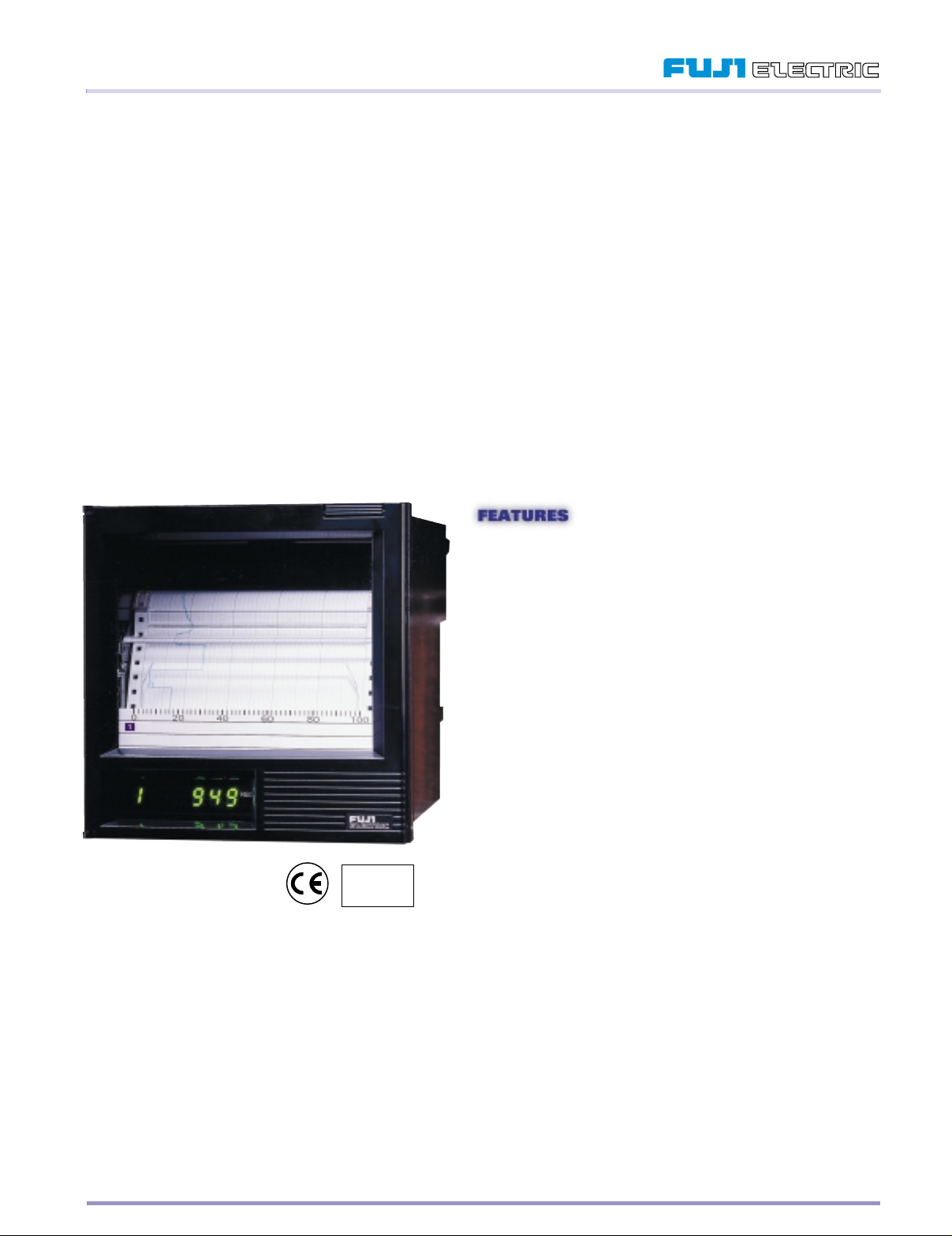
1- OR 2-CHANNEL INKJET STRIP-CHART RECORDER
Fuji Electric offers the latest in low-cost inkjet recording with the PHE Inkjet Series Recorder. This 100mm recorder, built with
polymer plastic mold technology to make it lightweight and durable, boasts many useful features. The PHE, which is available in
one or two channel recording, offers continuous analog trending on the same axis which eliminates the phase shift syndrome
exhibited by conventional pen recorders. In addition, it has many digital printing capabilities—periodic data, scale line, alarm
condition, burnout, and parameter printing.
Featuring an affordable inkjet print mechanism in a strip chart recorder, the PHE prints crisp, no-smudge characters without
physical contact with the paper. This printhead sprays the ink in tiny dots to create a trace in vivid colors for one or two channel
continuous recording. Utilizing a piezoelectric element, the PHE recorder creates stunning reports and print quality for the same
price as a pen recorder.
While analog pen recorders have many moving parts and frequently require maintenance and repairs in order to keep them in
working condition, the PHE recorders are extremely reliable and will give you years of trouble-free operation because they have a
third of the parts of conventional strip chart recorders. If that’s not enough, the PHE is backed by a three-year warranty.
So, if you’re looking for an economical recorder that offers many of the features found in higher-priced instruments, look no further
than the Fuji Electric PHE.
Fuji Electric is an
ISO 9001
facility
• Inkjet Printing Technology Without
Physical Contact with the Paper
Eliminates mechanical wear and provides crisp, color
recordings
• Low-Cost
Meets your budgetary demands
• Available in One- or Two-Channel
Continuous Trace
More capabilities your application demands
• Continuous Analog Trending on the
Same Axis
Without the phase shift syndrome exhibited by conventional
pen recorders
• Many Digital Printing Capabilities
Periodic data, scale line, alarm condition, burnout, and
parameter printing
• Built with Polymer Plastic Mold
Technology
The recorder is lightweight and durable
• The PHE Offers Many of the Features
Found in Higher-Priced Instruments
You get more recorder for your dollar
• Three-Year Warranty
Protects you from manufacturing defects
Information subject to change without notice. Prices in USD.
Page 2

PHE, CONTINUED
SPECIFICATIONS
GENERAL SPECIFICATIONS
DISPLAY METHOD LED (7-segment), 6-digits, green
DISPLAY CHARACTERS 7-seg. alphanumeric, 10mm high, 5mm wide
DISPLAY CONTENTS Channel Number: 1 digit
Measured Value: 5 digits (including sign).
Temperature: 1 digit below decimal point
Voltage/Current: as per scaling
Status Display: Code indicating alarm, burn-out,
carriage failure
Measured Value Display Cycle: Channel
changeover – 3 sec.
Data update in the same channel – 1 sec.
OPERATION KEYS 3 keys and one reset key
Keylock: Soft key lock available by key operation
PRINTING Printing Method: Inkjet
Ink Colors: Black, blue, red
Periodic Print-Out: Printing start line, channel
number, measured value, chart speed, date/time.
Printing intervals are automatically determined by
chart speed
Scale Print-Out: Scale lines for sequential
channels are printed alternately with periodic
print-outs. Printing intervals are automatically
determined by chart speed
Alarm Print-Out: At input alarm occurrence and
reset, prints channel number, alarm kind, and
date/time.
Burn-Out Print-Out: At burn-out occurrence,
prints channel number and date/time
Other Print-Outs: Recording start mark,
Chart speed change mark
KEY-ACTIVATED PRINTING These print-outs, activated by keying, suspend
analog recording. At the end of print-out analog
recording is resumed
Instantaneous Value: Print-out of measured value
(instantaneous value and engineering unit,
date/time, channel number)
Parameter List: Print-out of input signal, input
range, recording range, unit, alarm, input filter,
chart speed
Scale Print-Out: Print-out of scale line of desired
channel
Test Pattern: Print-out of color pattern and test
characters
POWER REQUIREMENT Rated Power Supply Voltage: 100 to120V AC or
200 to 240V AC
Range of Operating Voltage: 85 to 132V AC or
180 to 264V AC
Supply Frequency: 50/60Hz
Power Consumption: At 100 to 120V AC, 200 to
240V AC. Without options – approximately 13 VA.
With options – approximately 15 VA
OPTIONAL SPECIFICATIONS Alarm Output Relay: Form A contact output for two
points (1 channel) or four points (2 channels).
Outputs are available as individual or common
(ORoperation). Contact capacity – 240V AC, 3A;
30V DC, 3A (resistive load)
External Control Input: With external control input,
the following operations are possible. 2-stage
change-over of chart speed (set by the keypad).
Setting the sub chart speed to 0mm allows
recording start/stop change-over. External control
unit is not insulated, so an external relay should
be used. External contact capacity: 12V DC/0.05A,
Form A contact
PERFORMANCE AND Input Resistance:
CHARACTERISTICS Thermocouple, 50 mV range – ≥ 10MΩ.
500 mV range – ≥ 100KΩ.
5V and 50V range – ≥ 1MΩ
Chart Speed Accuracy: ±0.1% (expansion and
contraction of paper is not included)
Isolation: 100MΩ (between each terminal and
ground, at 500V DC)
Withstand Voltage:
Between two input terminals – 500V AC, 1 minute.
Power terminal to ground – 2000V AC, 1 minute.
Input terminal to ground – 500V AC, 1 minute
Reference Junction Compensation Accuracy:
K, E, J, T, N, L, U, PN: ±0.5°C. R, S, B, W: ±1°C
Common Mode Noise Rejection: 120 dB or more
at 50/60Hz ±0.1Hz
Normal Mode Noise Rejection: 30 dB or more at
50/60Hz ± 0.1Hz
INPUT AND ACCURACY
INPUT POINTS 1 or 2 continuous recording
MAX. ALLOWABLE Thermocouple, RTD and DC voltage: ±10V DC or
INPUT VOLTAGE less (50 mV, 500 mV range)
DC voltage input (5V, 50V range): ±100V DC
or less
BURNOUT FUNCTION When the thermocouple or RTD input is
disconnected, the recording is deflected to
full scale
INPUT RANGE Thermocouple: B, R, S, K, E, J, T, N, W, I, U, PN
RTD: Pt100Ω
DC voltage: -50 to +50 mV, -500 to +500 mV,
-5 to +5V, -50 to +50 V
Scaling is possible within the range of -32767 to
32767 (Decimal points may be placed as
necessary)
DC current: 4 to 20mA, converted into voltage with
10Ω or 250Ω shunt resistor
RECORDING
RECORDING METHOD Inkjet type, 3 colors
RECORDING POINTS 1 or 2 continuous
CHART PAPER Effective width – 100mm, Z-folding type,
length–15.08m.
MEASURING CYCLE 200msec/point
RECORDING CYCLE Depends on chart speed, 2 seconds or more.
Recording cycle (seconds) = 400 ÷ chart speed
(mm/hour), or 2 seconds, whichever is greater
RECORDING ACCURACY Indicating accuracy ±0.2%
RECORDING RESOLUTION 0.1mm
RECORDING COLORS 1 Continuous: Analog recording – violet, digital
printing – violet
2 Continuous: Channel 1 – red, channel 2 – blue,
digital printing – violet
CHART SPEED 10, 20, 24, 30, 50, 120, 200, 300, 400, 1000,
1200, 1500mm/hour, set from the keyboard
INK LIFE 1 Point: Approx. 20 months
(Depends on operating conditions)
2 Points: Approx. 12 months
(Depends on operating conditions)
ALARMS
SETTING METHOD Set from keyboard
NUMBER OF SETTINGS Max. 2 points for each channel (H & L types)
DISPLAY On detection, output relay number for each
channel is displayed
Information subject to change without notice. Prices in USD.
Page 3

α
=90~ 60°
PHE, CONTINUED
SPECIFICATIONS, CONTINUED
PRINT-OUT Print-out of channel number, alarm kinds, and time
lapse after recording start
HYSTERESIS AMPLITUDE About 0.2% of recording span
ALARM RELAY OUTPUT See Optional Specifications section
STANDARD FUNCTIONS
SKIP FUNCTION
Skips recording, indication or alarm of desired
channel
LISTING FUNCTION Instantaneous Values List: Prints measured value,
unit, lapsed time and channel number
Parameter List: Prints input signal, scale,
recording range, units, alarm, chart speed, etc.
Test Pattern: Prints test characters and color bars
Scale Print-Out: Prints scale of desired channel
PERIODIC PRINT-OUT Prints start time, channel number, measured value,
FUNCTION units, chart speed, and date/time
SCALE PRINT-OUT Prints scale of channels alternately with periodic
FUNCTION print-out
ALARM PRINT-OUT Prints channel number, alarm kind, and date/time
FUNCTION at alarm occurrence and reset
PV SHIFT FUNCTION Subjects measured value to summation and
subtraction to shift the values displayed or
recorded in order to offset the difference in Values
measured by other instruments
INPUT FILTER Slows the response to abrupt changes in input
signal for each channel (first order lag filter).
Time Constant Range: 0 to 255 sec.
BURN-OUT FUNCTION In case of thermocouple or RTD open circuiting,
recording swings to the maximum value side of
range and simultaneously displays and prints
the input
OPERATING AND STORAGE CONDITIONS
NORMAL OPERATING
ENVIRONMENT Humidity Limits: 20 to 80% RH, non-condensing
Temperature Limits: 32°to 122°F (0°to 50°C)
(temperature x humidity < 3200)
Vibration: 10 to 60Hz, 0.2m/s2 (0.02g) or less
Mounting Position: Front inclination 0°, rear
inclination 30°, left/right inclination 0°
Signal Source Resistance: Thermocouple Input:
1kΩ or less. Voltage Input – Less than 0.1% of
input resistance. RTD Input – Less than 10Ω per
wire (resistance of each wire of 3-wire system
should be balanced with others)
Shock: No external shock
INPUT SIGNAL SOURCE Thermocouple: 10µV per 100Ω
RESISTANCE OR WIRING Voltage Input: Variation of 0.1% change of
RESISTANCE INFLUENCE resistance. Change in indication – ±(0.1% of
reference range + 1 digit) maximum. Change in
recording – ±0.2% of recording span, max.
RTD: Variations of resistance with changes in 10Ω
per wire. Change in indication – ±(0.1% of
reference range + 1 digit) maximum. Change in
recording – ±0.2% of recording span, max.
TEMPERATURE INFLUENCE Change in Indication: ±0.2% of reference
range/10°C, max.
Change in Recording: ±0.5% of recording
span/10°C, max.
Reference Junction Compensation: ±0.27°C/10°C,
max.
CHART PAPER INFLUENCE Standard Temperature/Humidity: 20°C, 65% RH
Expansion at 85% RH: 0.4% max.
Contraction at 35% RH: 0.5% max.
VIBRATION INFLUENCE Linear vibration with 10-60Hz and 0.02g is applied
to each of 3 directions for 2 hours.
Change in indication: ± (0.1% of reference range +
1 digit) max.
Change in recording: ±0.2% of recording span,
max.
REFERENCE STANDARDS Safety Standard: IEC 1010-1 (1990)
EMC Standard: EN50081-1 (1992), EN50082-1
(1992)
Dust/Drip-Proofing: IP50
STRUCTURE
MOUNTING METHOD
Panel flush mounting,
side by side mounting is
possible. Inclination angle:
90° to 60° from horizontal
EXTERNAL DIMENSIONS 5.67 x 5.67 x 6.89in. (144 x 144 x 175mm)
(WxHxD) Panel Cutout: 137mm x 137 mm (+1.5, -0)
CASE Plastic mold, color– black
EXTERNAL TERMINALS Screw terminals (M4 thread)
Information subject to change without notice. Prices in USD.
Page 4

PHE, CONTINUED
PHE ORDERING INFORMATION
P H AE B C D 2 EFE E V
To create an ordering code fill in the boxes above with the appropriate number and/or letter from the corresponding box below.
Box A: Recording Points
1 = 1 continuous recording
2 = 2 continuous recording
Box B: Input Signal for Ch. 1
X = B Thermocouple
R = R Thermocouple
S = S Thermocouple
K = K Thermocouple
E = E Thermocouple
J = J Thermocouple
T = T Thermocouple
N = N Thermocouple
W = W Thermocouple
L = L Thermocouple
U = U Thermocouple
P = PN Thermocouple
H = Pt100Ω RTD
A = DC 1-5V
B = DC 4-20mA with shunt resistor
C = DC 10-50mA with shunt resistor
M = DC ±50mV
Q = DC ±500mV
V=DC ±5V
F = DC ±50V
Box C: Input Signal for Ch. 2
Y = None
X = B Thermocouple
R = R Thermocouple
S = S Thermocouple
K = K Thermocouple
E = E Thermocouple
J = J Thermocouple
T = T Thermocouple
N = N Thermocouple
W = W Thermocouple
L = L Thermocouple
U = U Thermocouple
P = PN Thermocouple
H = Pt100Ω RTD
A = DC 1-5V
B = DC 4-20mA with shunt resistor
C = DC 10-50mA with shunt resistor
M = DC ±50mV
Q = DC ±500mV
V=DC ±5V
F = DC ±50V
Box D: Power Supply
3 = 100V/120V AC, 50/60 Hz
4 = 200V/240V AC, 50/60 Hz
ACCESSORIES & SPARE PARTS
PHZH1001 Recording Head
PEX00DL1-5000B Chart Paper 1 Box (6 pkg.)
— 10 or 250Ω Shunt Resistor
Box E: Scale Range
5Y = One channel
55 = Two channels
Box F: Alarm Output
0 = None
1 = 1-ch. recorder, 2-point/no external control
A = 1-ch. recorder, 2-point/with external control
2 = 2-ch. recorder, 4-point/no external control
B = 2-ch. recorder, 4-point/with external control
Information subject to change without notice. Prices in USD. 011110
 Loading...