

Page 1
Instruction Manual
MICROJET RECORDER
TYPE: PHC
INP-TN3PHCVi-E
Page 2

PREFACE
Congratulations on your purchase of Fuji Micro-jet Recorder (Type: PHC)
• Read this instruction manual carefully to ensure correct installation, operation and preparation.
Incorrect handling may lead to accident or injury.
• Specifications of this unit is subject to change without prior notice for improvement.
• Modification of this unit without permission is strictly prohibited.
Fuji will not bear any responsibility for a trouble caused by such a modification.
• This instruction manual should be kept by the person who is actually using the unit.
• After reading the manual, be sure to keep it at a place easy to access.
• This instruction manual should be delivered to the end user without fail.
Manufacturer : Fuji Electric Co., Ltd.
Type : Shown on nameplate of Micro-jet recorder
Date of manufacture : Shown on nameplate of Micro-jet recorder
Product nationality : Japan
Request
• It is prohibited to transfer part or all of the manual without
Fuji's permission.
• Description in this manual will be changed without prior
notice.
Fuji Electric Co., Ltd. 1996
Issued in Dec., 1996
Rev. 1st edition July, 1997
Rev. 2nd edition May, 1998
Rev. 3rd edition March, 2000
Rev. 4th edition Nov., 2002
Rev. 5th edition April, 2005
Rev. 6th edition March, 2008
Rev. 7th edition April, 2011
Rev. 8th edition Oct., 2011
Rev. 9th edition March., 2012
- i -INP-TN3PHCV-E
Page 3
CAUTION ON SAFETY
First of all, read this "Caution on safety" before using the unit.
• The cautionary descriptions listed here contain important information about safety, so they should
always be observed. Those safety precautions are ranked to 2 levels, DANGER and CAUTION.
Wrong handling may cause a dangerous situation, in which
DANGER
CAUTION
there is a risk of death or heavy injury.
Wrong handling may invite a dangerous situation, in which
there is a possibility of medium level trouble or slight injury
or only physical damage is predictable.
PROHIBITION
Caution on Installation
DANGER
CAUTION
Items which must not be done are noted.
• This unit is not an explosion-proof type. Do not use it in a place
with explosive gases to prevent explosion, fire or other serious
accident.
• For installation, select a place observing the operating conditions noted in the instruction manual. Installation at an unsuited
place may cause fall, trouble or malfunction.
• The unit must be installed correctly as shown in the instruction
manual. Incorrect installation may cause fall, trouble or malfunction.
• During installation work, keep the inside of the unit free from
entry of cable chips or other foreign objects as it may cause fire,
trouble or malfunction.
• This unit is a component device used for instrumentation. It is
CAUTION
- ii - INP-TN3PHCV-E
mounted on a panel or in a rack in an equipment.
•This unit conforms to IEC61010-1 Safety standards, overvoltage category II and pollution degree 2. Protection class is double
insulation. However the heat sink of power supply on the rear
side is basic insulation.
• Only power supply 24V DC and part of options(with limitations)
are conformed to UL61010-1 standard. Regarding limitations
of power supply, please refer to Item 4.3. Regarding limitations
of option, please refer to Item 1.3 and 12. And if the equipment
is used in a manner not specified by Fuji Electric Co., Ltd., the
protection provided by the equipment may be impaired.
Page 4
CAUTION
Caution of Wiring
DANGER
• EMC conforms to EN61326-1, Class A (used for controlled electromagnetic environment((EMI)) and used for housing
areas((EMS)) Therefore this unit is designed to operate in a controlled electromagnetic environment ,i.e. where radio frequency
transmitters such as mobile phone may not be used in close proximity. In addition emissions which exceed the levels required by
the standard may occur when this unit is connected to other equipment.
• Input signals and communication interface should be of SELV
(safety separated from hazardous voltage).
• Only power supply 24DC V and part of options (with limitations) are conformed to UL61010-1 standard.
Please refer to Item1.3 and 12.
•Wiring work must be performed as specified. If the unit is not
earthed, it would result in electric shocks or malfunction.
• Be sure to connect power source that matches the rating. Connection of incorrect rating of power source may lead to fire.
• Before starting wiring work, be sure to turn OFF the main power
to prevent electric shocks.
• Wiring materials to be used must meet the rating. Use of materials which do not withstand the rating may cause a fire accident.
Caution on Maintenance
DANGER
•When disposing of the recording head, put it in a vinyl bag
and seal it to prevent the diffusion of ink. It should be handled
as an imcombustible object when disposing of it.
• Ink is harmful to human body. Observe the following emer-
gency treatments.
.
When ink gets in eyes, wash out for at least 5 minutes
immediately with much clean water, and ask your doctor
for treatment at once.
.
When ink gets on skin, wash out and clean skins with
soap and water.
.
When ink is breathed in, move to a clean place immediately. If necessary, ask your doctor for treatment at once.
• Do not touch the connector at the rear of the carriage mount-
ing the recording head to avoid the risk of electric shocks.
- iii -INP-TN3PHCV-E
Page 5
Caution on Use
r
DANGER
• If the fault or anomaly of the device may cause serious accident or troubles to other devices, externally install appropriate protective circuit to avoid accidents.
•
The instrument has no power fuse. Install it if necessary.
fuse is blown out, check and remove the cause of it, and replace it with new one specified in the instruction manual. Do
not use any other fuse or short it, as it may cause electric
shocks or fire.
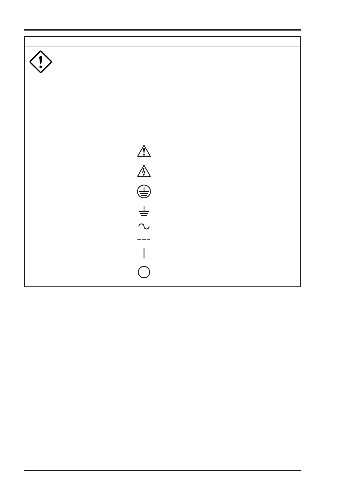
• The following safety symbols are used on PHC SERIES.
Caution (To avoid injury, operator must refe
to the explanation in the manual.)
Be careful of electric shock.
Protective ground terminal
Functional ground terminal (do not use this
terminal as a protective ground terminal)
When
Alternating current
Direct current
ON (power)
OFF (power)
- iv - INP-TN3PHCV-E
Page 6

CONTENTS
PREFACE .................................................................................................................................. i
CAUTION ON SAFETY .............................................................................................................ii
1. INTRODUCTION ............................................................................................................. 1-1
1.1 Microjet recorder......................................................................................................................1-1
1.2 Product check ...........................................................................................................................1-1
1.3 Check on type and specification...............................................................................................1-2
2. NAMES AND FUNCTIONS OF PARTS........................................................................... 2-1
3. MOUNTING METHOD..................................................................................................... 3-1
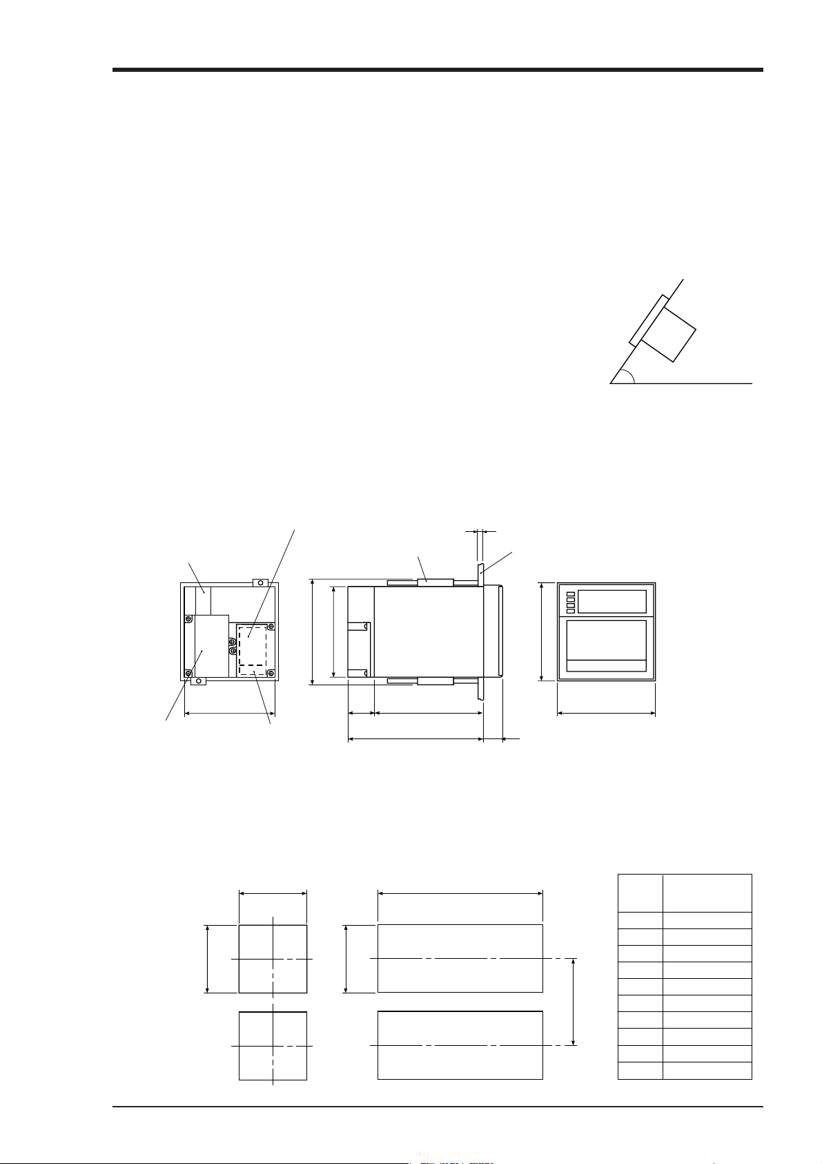
3.1 Mounting location .................................................................................................................... 3-1
3.2 External dimensions and panel cut out dimensions .................................................................3-1
3.3 Method of mounting onto panel ............................................................................................... 3-2
4. WIRING ........................................................................................................................... 4-1
4.1 Before doing the wiring ........................................................................................................... 4-1
4.2 Connection of wires to terminals .............................................................................................4-2
5. SET-UP ............................................................................................................................ 5-1
5.1 Loading chart paper..................................................................................................................5-1
5.2 Recording head installation (replacement)...............................................................................5-5
5.3 Changing the type of input signals......................................................................................... 5-10
6. OPERA TING AND ACTIONS .......................................................................................... 6-1
6.1 Before running the equipment..................................................................................................6-1
6.2 Power switch-on and states ......................................................................................................6-2
6.3 Test pattern print-out ................................................................................................................6-3
6.4 Actions during operation.......................................................................................................... 6-3
6.5 Displays and print-outs on detection (cancellation of alarm) .................................................. 6-5
6.6 Displays and print-outs on occurrence of burn-out.................................................................. 6-5
6.7 Over-range, under-range display and abnormal input display .................................................6-6
6.8 Display and record when chart paper runs out ("Chart End" display) .....................................6-6
6.9 Display and record when the recording head ink is low ("Ink Out" display) ..........................6-6
6.10 Display when data backup batteries need to be replaced ("Battery End" display) .................. 6-7
6.11 Display of fault in recording head carriage ("Carriage Alarm" display).................................. 6-7
6.12 Order of priority of state displays ............................................................................................6-7
7. SETTING AND CHECKING PARAMETERS ................................................................... 7-1
7.1 Setting and checking ................................................................................................................ 7-1
7.2 Outline of procedure for setting parameters............................................................................. 7-4
7.3 Pass code setting....................................................................................................................... 7-6
7.4 Setting the chart speed ............................................................................................................. 7-7
7.5 Setting alarms........................................................................................................................... 7-9
Chapter 3,4 and chapter 8 should be observed for installation and maintenance of the unit. So, it must be performed by qualified engineers.
CAUTION
- v -INP-TN3PHCV-E
Page 7

7.6 Setting the recording mode ....................................................................................................7-10
7.7 Setting record ranges.............................................................................................................. 7-14
7.8 Setting kind of input, skip, unit, filter, scaling and subtraction.............................................. 7-16
7.9 Setting Tag Nos. ..................................................................................................................... 7-22
7.10 Message print specification .................................................................................................... 7-23
7.11 List print-out specification ..................................................................................................... 7-26
7.12 Daily report specification .......................................................................................................7-27
7.13 Specifying totalize function ...................................................................................................7-28
7.14 Transmission specification (option) .......................................................................................7-30
7.15 Setting the time ...................................................................................................................... 7-32
7.16 Method of ink out clear ..........................................................................................................7-33
7.17 Turning the chart illumination lamp on/off (option) .............................................................. 7-34
8. MAINTENANCE-INSPECTION ....................................................................................... 8-1
9. APPLICATION FUNCTIONS ........................................................................................... 9-1
9.1 Adjustment of backlash............................................................................................................ 9-1
9.2 Zero/span adjustment for analog trend recording position.......................................................9-2
9.3 Setting of alarm latch and integrated total value print-out....................................................... 9-3
9.4 Setting of PV shift ....................................................................................................................9-4
9.5 User definable unit ................................................................................................................... 9-5
9.6 Setting of record error external output .....................................................................................9-6
9.7 Calibration of measured value ................................................................................................. 9-6
9.8 Change of record color............................................................................................................. 9-8
9.9 Language selection................................................................................................................... 9-8
10. TROUBLESHOOTING ................................................................................................... 10-1
11. EXAMPLES OF RECORD AND PRINT-OUTS.............................................................. 11-1
11.1 Periodic print-outs, scale print-outs .......................................................................................11-1
11.2 Digital print-out (Instantaneous values) .................................................................................11-2
11.3 Parameter list print-out...........................................................................................................11-2
11.4 Test pattern .............................................................................................................................11-3
11.5 Scale print-outs....................................................................................................................... 11-3
11.6 Daily report print-out .............................................................................................................11-4
11.7 Data sum list print-out............................................................................................................11-5
11.8 Message print (manual print) .................................................................................................11-5
11.9 Logging ..................................................................................................................................11-6
11.10 Alarm print-outs .....................................................................................................................11-6
11.11 Burn-out print-out ..................................................................................................................11-6
11.12 Ink dry-up warning print-out ..................................................................................................11-6
11.13 Record start mark ................................................................................................................... 11-7
11.14 Chart speed change mark .......................................................................................................11-7
11.15 Auto range change mark ........................................................................................................ 11-7
12. SPECIFICATION............................................................................................................ 12-1
- vi - INP-TN3PHCV-E
Page 8
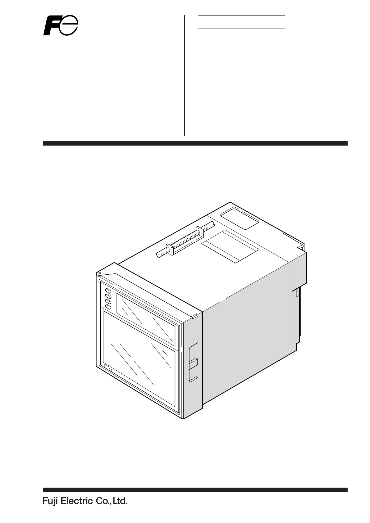
1. INTRODUCTION
1.1 Microjet recorder
① This recorder is a multirange input recorder 100mm wide which can record up to a maximum of 6
points using thermocouple/resistance bulb and DC voltage input signals.
② It effects high-speed recording and gives clear analog trend records and digital print-outs in 6
colors.
③ The analog trend records can be given as continuous record type or as intermittent (dot) records.
(See Section 1.3, Format specification.)
④ As well as providing records of measurement values, the standard unit has a wide range of print-
out functions comprising, e.g., the print-out of dates, chart speed, measurement ranges, Tag Nos.,
daily reports and integrated totals.
⑤ Operation of the equipment is simple thanks to an easy-view display section which permits key-in
of various items of set data.
1.2 Product check
Upon receiving the unit, check the appearance and accessories to make sure that they are not damages.
Also, check that the accessories are supplied correctly.
Check on accessories
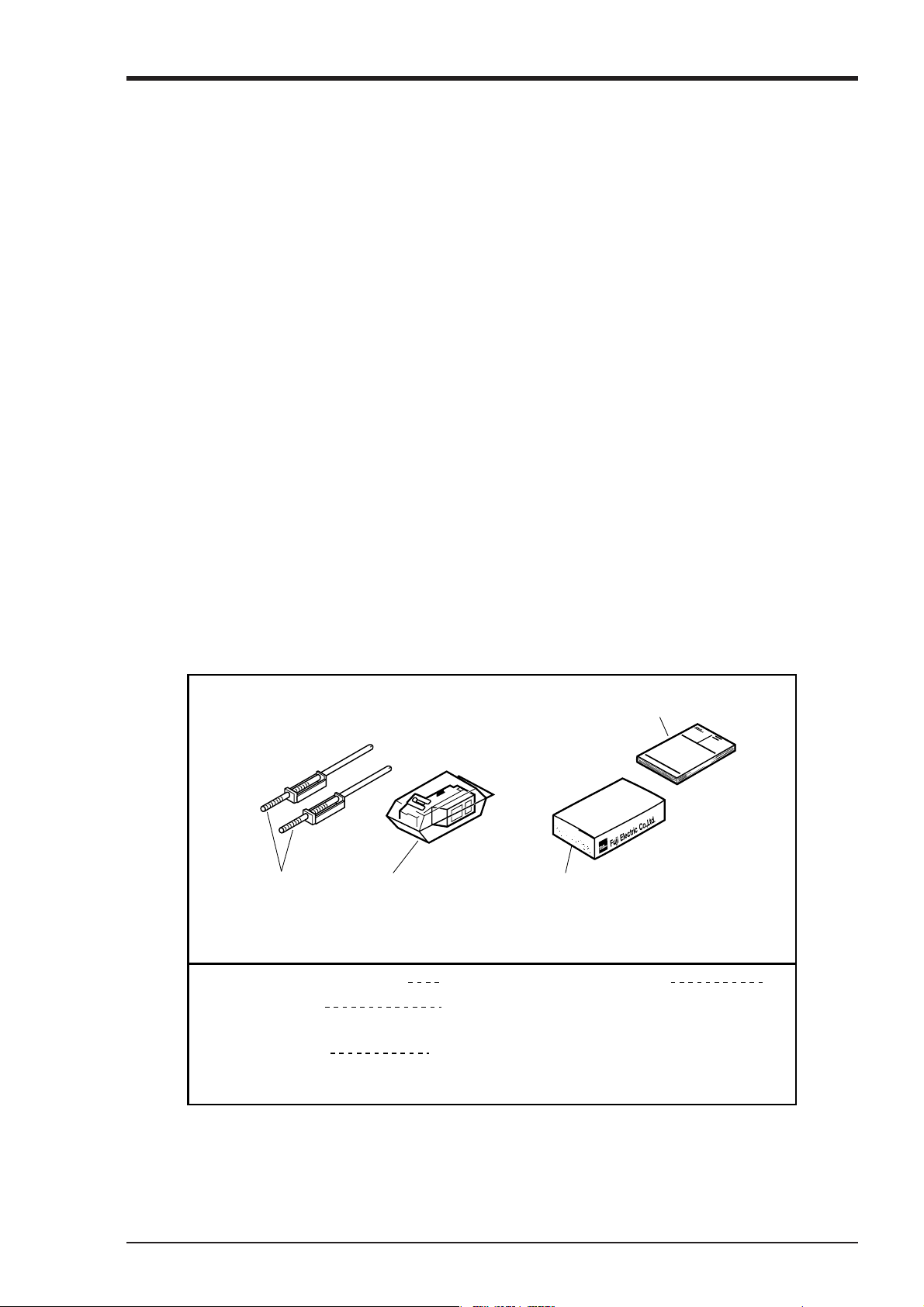
The unit comes with the accessories shown in Fig. 1-1. Please check that they are all there.
④ Instruction Manual
取
扱
説
明
書
① Panel-mounting
attachments
② Recording head, with
cloth for absorbing ink
(Keep the ink blotting ccloth so as not to be lost.)
① Panel-mounting attachments
② Recording head
with cloth for absorbing ink
③ Recording paper
(The standard recording paper No. is
PEX00DL1-5000B)
2
1
1 pack
富
士
電
機
株
式
会
社
③ Recording paper
④ Instruction Manual 1
Fig. 1-1 Accessories
1 - 1INP-TN3PHCV-E
Page 9
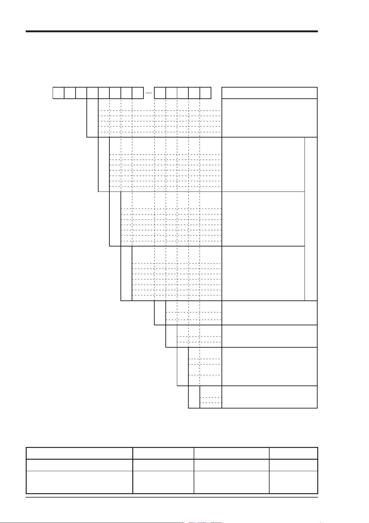
1.3 Check on type and specification
The data plates note the type name, etc. Please check to see that you have got a unit with the specification you ordered. (There are data plates on the top surface of the case and in the main unit.)
12345678 9
PHC 3
1
2
3
6
7
0
1
2
3
4
5
6
0
1
2
3
4
5
6
10 11 12 13 places
V
/
Y
Description
Number of recording points
1 continuous record
2 continuous record
3 continuous record
6 continuous record
6 dot records
Number of input signal points
(thermocouples)
None
1 points
2 points
3 points
4 points
5 points
6 points
Number of input signal points
(resistance bulbs)
None
1 points
2 points
3 points
4 points
5 points
6 points
0
1
2
3
4
5
6
•Value of input signal prior to delivery
Thermocouple : K 0 to 1200°C
D
L
Resistance bulbs : Pt100 0 to 500°C
DC voltage : DC -5 to +5V
•Relations between input signal specifications
and recording channels
Ex.)If 3 thermocouple points, 2 resistance bulb
points and 1 DC voltage points are specified.
channels 1 - 3 are thermocouple
channels 4 - 5 are resistance bulbs and channels 6 is DC voltage.
Note: After purchasing the unit, the type of input sig-
nal can be changed within the number of recording points (see Item 5.3).
Note1) These functions are not conformed to UL61010-1 standard.
Note2) It is conformed to UL61010-1 standard with conditions attached.
Please refer to Item12 "Optional specifications" for details.
• Supplementary supplies
Number of input signal points
(DC voltage)
None
1 points
2 points
3 points
4 points
5 points
6 points
Power Supply
100 to 240V AC 50/60Hz Note 1)
24V DC
A
B
0
1
2
Y
R
Asterisks (*) indicate options
CHART illumination*
Without
With
Alarm output/external control*
None
6-point alarm output (la contact)
/with 3-point external control Note 2)
6-point alarm output (1b contact)
/with 3-point external control Note 1)
Communication*
None
With RS-485 Note 1)
the number of points of the 4th place.
The total number of points should be equal to
Product name Type Specification Sales units
Recording head PHZH1002 1 per unit 1
Recording paper (uniform 50 scale) PEX00DL1-5000B Approximately 15m 6 packs
(6 packs/box)
1 - 2 INP-TN3PHCV-E
Page 10
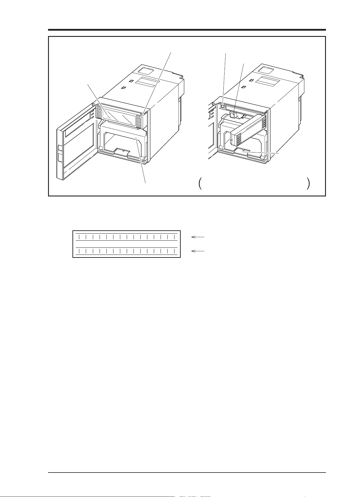
2. NAMES AND FUNCTIONS OF PARTS
(1) Display section
(6) Keying operation section
(3) Power supply switch
(4) Paper feed
unit drawout
lever
(5) Chart paper holder
Hold the left end of the display unit and
pull it forward as shown above.
(2) Recording head
(1) Display section
For displays such as measurement data and displays of various parameters and comments
Display of units and data for each channel
Display of various parameters, comments
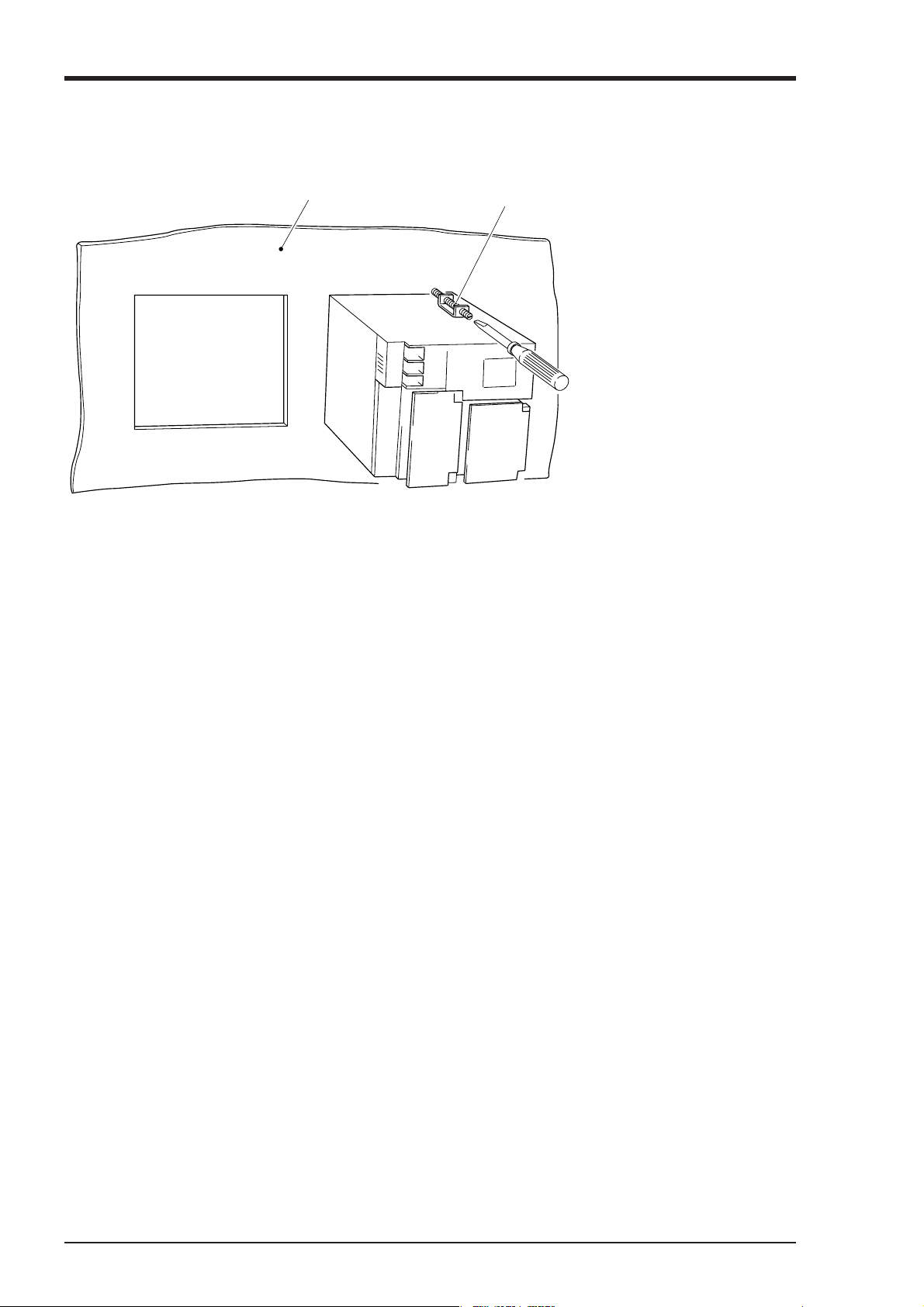
(2) Recording head
This is a recording head which serves for analog trend recording and digital print-outs. As this is
not installed in the main unit at the time of delivery, please install it referring to Section 5.2.
(3) Power supply switch
Used to turn the power on and off.
(4) Paper feed unit drawout lever
When setting (or replacing) chart paper, push down the drawout lever. The paper feed unit will
come out. If it does not come out, pull it forward while holding the lever down.
(5) Chart paper holder
The chart paper holder is used to feed paper smoothly.
2 - 1INP-TN3PHCV-E
Page 11
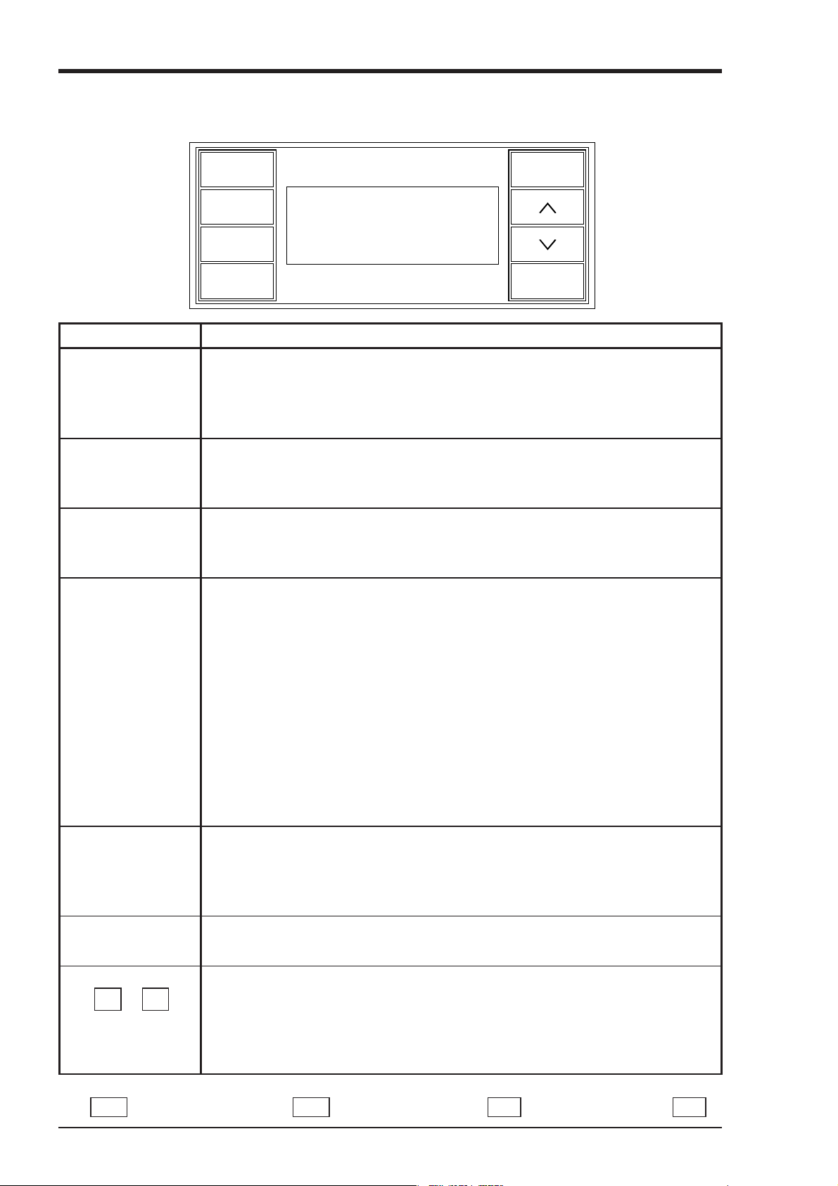
(6) Keying operation section
This is used for setting various parameters, making checks and running the equipment.
Name of key
RECORD
LIST
FEED
RECORD
DISPLAY
LIST
FEED
SELECT
ENTRY
Function
Operation key for starting and stopping recording.
Recording starts when the key is pressed once and stops when the key is pressed
again.
This key is ineffective during print-out of data or lists.
This is used for effecting print-out of data (instantaneous values).
If you wish to stop the print-out partway through, press the key again.
This key is alwys effective.
Chart paper fast-feed key
Feed speed is 3mm/s at the beginning of press, and about 8mm/s after 1 second.
This key is always effective.
DISPLAY
SELECT
ENTRY
∧ ∨
(up) (down)
1. Used for changing the data display. The following 5 items are selected at each
press.
(1) Data of all channels are displayed in order, except for the skip channel.
Data display is updated at intervals of 1 second and channels are selected
every 3 seconds.
(2) Display only of the data of specific channels. The data display is updated
once every second.
(3) No. 1 to 6 channels are displayed simultaneously, and data display is up-
dated at 1 second intervals.
(4) Display of the date and time.
2. This key is used for shifting from a set mode to the data display mode.
This key is ineffective during print-out of data or lists.
1. Used for shifting from the data display mode to a set mode.
2. Is used for effecting sequential read-out of parameters during operation in a
set mode.
This key is ineffective during print-out of data or lists.
Is used to register set data.
This key is effective only during set mode operation.
Used to scroll numerical values up and down.
The values are scrolled up or down 1 count each time the relevant key is pressed.
Holding a key depressed for more than 0.5 seconds results in a fast up/down
scroll at a rate of 5 counts/second and holding it depressed for a further 2 seconds
results in an ultra-fast scroll of 55 counts/second.
Note) In this instruction manual some display of the keys are abbreviated as follows. RECORD key is indicated
REC , DISPLAY key is indicated DISP , SELECT key is indicated SEL , ENTER key is indicated ENT .
2 - 2 INP-TN3PHCV-E
Page 12
3. MOUNTING METHOD
Power supply terminal
Input terminal
136.4
Alarm external
control unit
(Option)
Transmission
terminal
(Option)
199
41 158
26
136.4
174.4
Mounting attachment
2≦ t ≦30
t
Panel
144
144
PANEL CUTOUT
137
+1.5
0
137
+1.5
0
175
MIN
137
+1.5
0
L
+ 2
0
L
+ 2
0(mm)
For single unit mounting For left/right tight fit mounting
Number
of
units
2
3
4
5
6
7
8
9
10
n
Weight : Approximately 2.1kg (without options)
Approximately 2.2kg (with all options)
Power consumption : Approximately 26VA (100V AC with all options)
Less than 26VA (26.4V DC with all options)
282
426
570
714
858
1002
1146
1290
1434
(144×n)
-
6
This unit is designed to be panel mounted.
3.1 Mounting location
Select the following location for mounting the unit.
(1) A place that is not subject to vibration or impact.
(2) A place where there is no corrosive gas.
(3) A place that is subject to little temperature variation and is close to
normal temperature (23°C)
(4) A place that is not struck directly by strong radiant heat.
(5) As humidity affects the ink and recording paper, select a place that
is in the range 20 to 80% RH.
(6) Mount the unit horizontally, with no tilt to the left or right.
(The forward tilt should be 0° but the unit may be inclined 0 to 30°
rearwards.)
∠ α
α = 60 to 90°
3.2 External dimensions and panel cut out dimensions (unit: mm)
3 - 1INP-TN3PHCV-E
Page 13
3.3 Method of mounting onto panel
Panel
Screw
• Using the supplied mounting
fixture, tighten the upper and
lower screws until the panel is
fixed.
• The panel to be used should
be more than 2mm thick.
3 - 2 INP-TN3PHCV-E
Page 14
4. WIRING
4.1 Before doing the wiring
To carry out wiring, remove the unit's rear cover (Notes)
① When wiring the power supply unit, use vinyl-insulated 600V cables (JIS C 3307) or equivalent
cables.
② For thermocouple input, be sure to use a compensated lead wire.
③ Input signal cables should be wired separately as far as possible (30cm or more) from power lines
and high-voltage lines to minimize the effect of inductive noise. Shielded cables should preferably
be used. In this case, the shield braids should be earthed at one point.
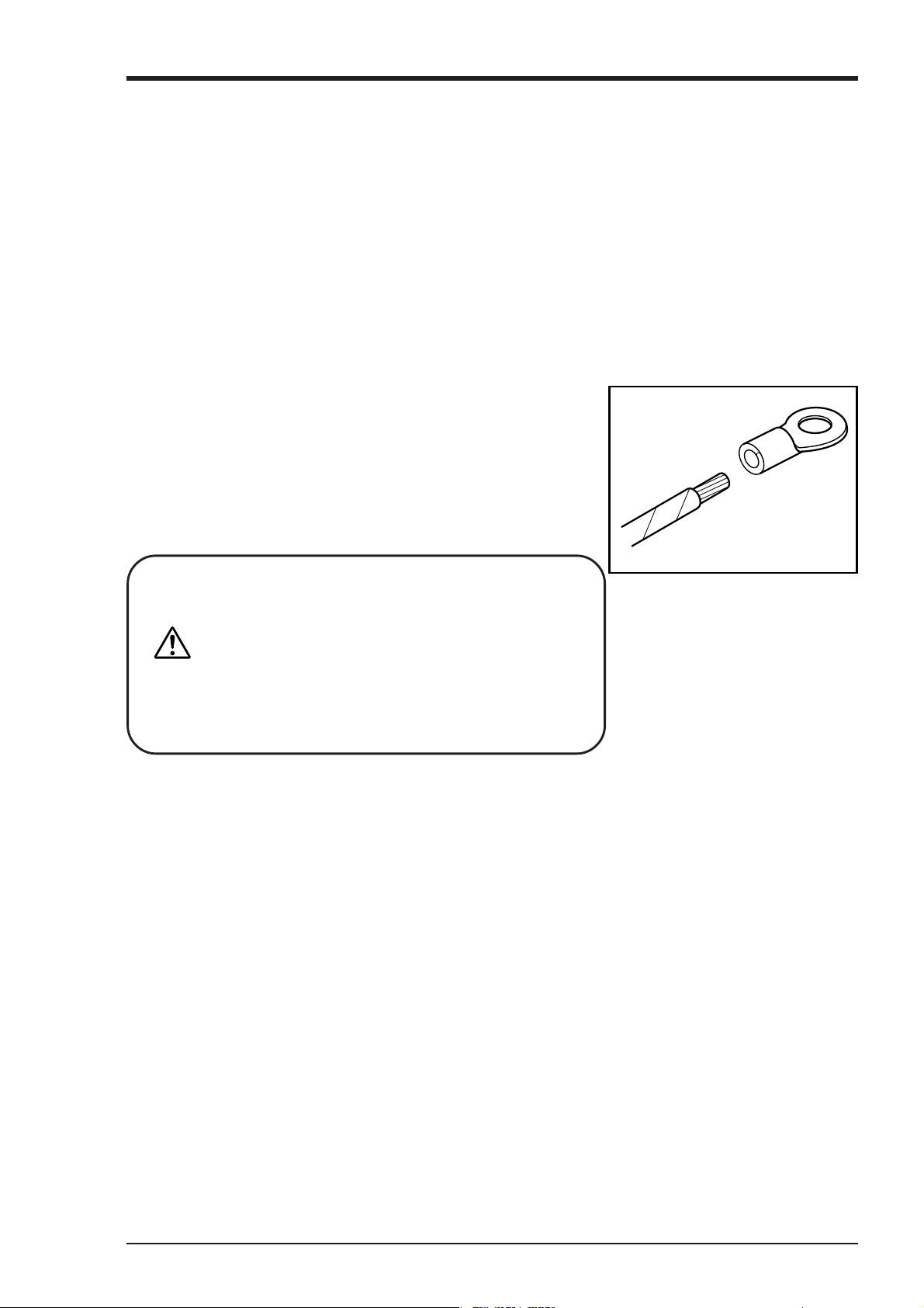
④ For wiring the terminals, use a maximum of 2 crimp style terminals.
Notes
(1) At the completion of wiring of the input terminals, be sure
to close the rear cover to ensure the compensation of reference contact when thermocouple input is used.
(2) For connection of lead wires to terminals, use of sleeve-
insulated clamping terminals (for M4 screws) is recommended.
CAUTION
The recorder is not provided with a power fuse.
Use an external power fuse.
.
In case the power supply is 100 to 240V AC
Recommended fuse rating : T2A, 250V AC
.
In case the power supply is 24V DC
Recommended fuse rating : Maximum 3A,
minimum 24V DC
4 - 1INP-TN3PHCV-E
Page 15
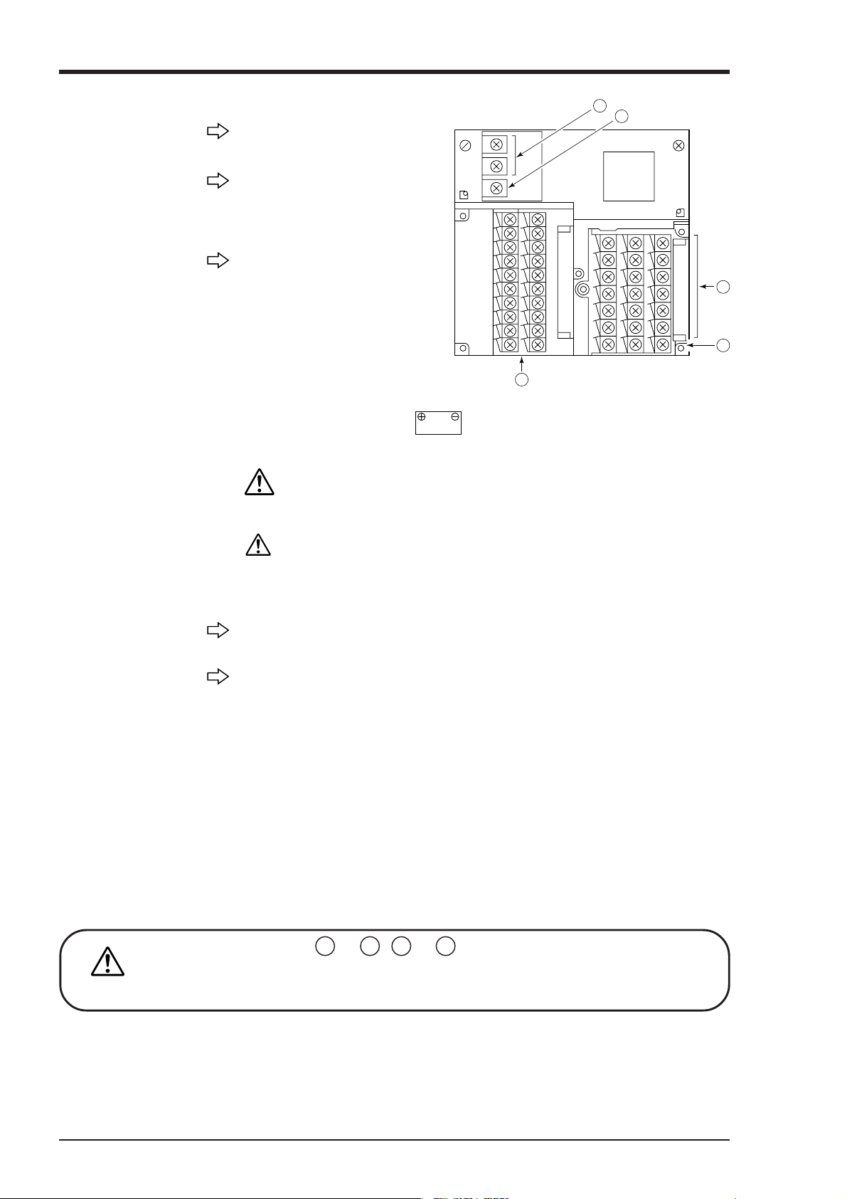
4.2 Connection of wires to terminals
(1) Input terminals
Connect signal leads for each
channel.
3
4
(2) Alarm,
external
control unit
(option)
(3) Power terminal
Connect the alarm signal outputs
and external control signal inputs
(for alarms 1 to 6, external controls 1 to 3).
1) Connect the power cables to
AC/AC terminals. (Supply
voltage 100 to 240V AC products (9th digit of code symbol: “D”))
This is the power for the
specified type of 100 to 240
V AC (50/60Hz)
2) Connect power cable to
DC24V
ucts (9th digit of code symbol: “L”))
If you apply to exceeding 30V AC (Example: 100V AC and 240V AC)
to 24V DC power materials, the equipment will be broken and never be
fixed.
For UL Certification,this unit is only supplied by 24V DC, comply-
CAUTION
ing with Limited Energy Circuit.
1
5
2
terminals. (Power voltage 24V DC prod-
(4) Ground
terminal
(5) Transmission
terminal
(option)
Alarm output terminals ( 14 to 19 , 24 to 29 ) are of overvoltage category I. Other
terminals (input signals, communication interface) are for SELV signals (safety sepa-
CAUTION
rated from hazardous voltage).
3) Power source to be connected should be free from noise.
D-class grounding with ground resistance of 100Ω or less.
Connect the transmission signals.
4 - 2 INP-TN3PHCV-E
Page 16
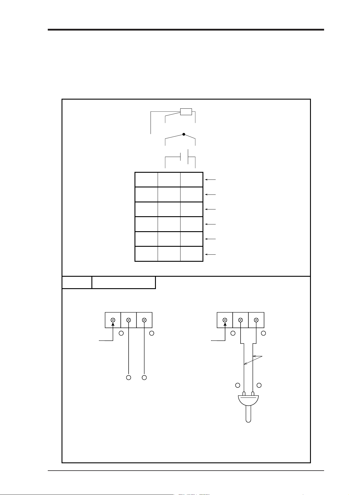
(1) Connection of input terminals
① Each channel has its own input terminal No.
② Connect input terminals confirming the relation between the number of input points shown in the
code symbols and their channels (see Item 1.3).
③ When the kinds of input signals have been changed after purchase of the unit (see Item 5.3), be sure
to connect the terminals of corresponding channels.
Resistance bulb
ABb
Thermocouple
+
DC voltage
Example
Blank
13 12 11
23 22 21
33 32 31
423 42 41
53 52 51
63 62 61
Input terminal wiring
DC voltage input
1213 11 2223 21
–
Input 1
Input 2
Input 3
Input 4
Input 5
Input 6
Thermocouple input
+
–
+
Blank
+
–
DC voltage input
Compensating
leads
–
+
Thermocouple
Note : Avoid using thermocouple input with
wiring parallel to other instruments.
4 - 3INP-TN3PHCV-E
Page 17
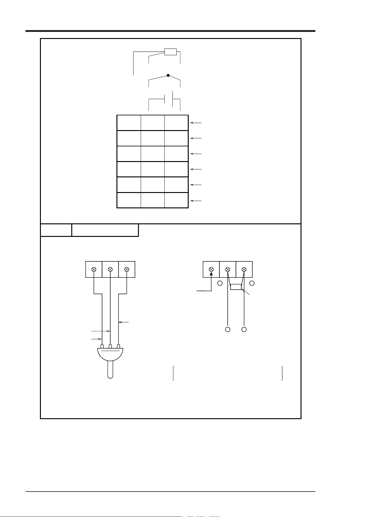
Resistance bulb
ABb
Thermocouple
+
DC voltage
Example
13 12 11
23 22 21
33 32 31
423 42 41
53 52 51
63 62 61
Input 1
Input 2
Input 3
Input 4
Input 5
Input 6
Input terminal wiring
Resistance bulb input DC current input
4243 413233 31
bB A
–
Blank
+
Shunt
resistance
A
+
B
b
–
DC current input
Example : 10Ω ±0.1% shunt resistance is used
for 4 to 20mA and 10 to 50mA input.
Resistance
bulb
Note :
In this case, ±500mV input range is
available. See Item 5.3.
DC current is converted into voltage by shunt
resistor (10Ω):
In 4 to 20mA DC : 40 to 200mV DC
In 10 to 50mA DC : 100 to 500mV DC
4 - 4 INP-TN3PHCV-E
Page 18
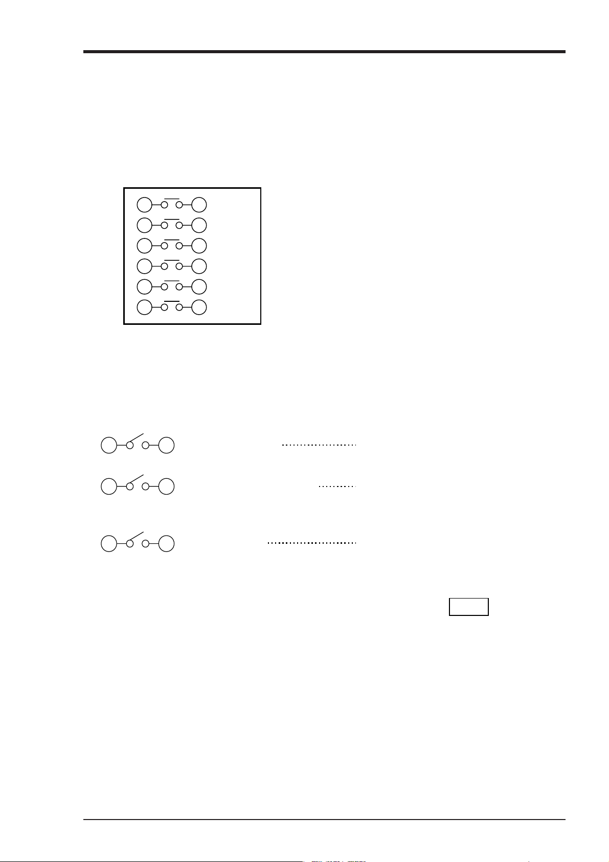
(2) Alarm output/remote control unit (option)
About alarm outputs :
(1) Alarms can be set at 6 points in each channel and alarm outputs are provided as an option for up to
a maximum of 6 points.
(2) When an alarm is detected, the relevant terminals are shorted.
1a contact output : Relay contact capacity 240V AC/3A, 30V DC/3A (resistive load)
1b contact output : Relay contact capacity 125V AC/0.4A, 30V DC/2A (resistive load)
14 24
15 25
16 26
17 27
18 28
19 29
About remote control inputs :
(1) This performs the functions 'Recording operation start/stop', 'Two-stage changeover of recording
paper speed' and 'Data (instantaneous value) print-out' in response to contact signals from outside
the instrument.
(2) There are separate wiring terminals for the different functions.
11 21
Alarm 1
Alarm 2
Alarm 3
Alarm 4
Alarm 5
Alarm 6
(DI1) Record start
Note : If lamps are used on the outside, insert a resistor to pre-
vent surge current.
Also, if relays or solenoids are used, insert elements for
contact protection (diodes, surge killers, etc.).
Recording starts when the contact is closed
and stops wht is open.
12 22
(DI2) Chart speed change
The chart speed is the remote mode speed
when the contact is closed and the normal
operaiton speed when the contact is open.
13 23
(DI3) Data print
Print-out starts when the contact is closed
and goes on right to the end even if the
contact is opened partway throught the printout. If you wish to stop print-out partway
through, press the LIST key on the front
panel.
4 - 5INP-TN3PHCV-E
Page 19
Note 1: As the external control unit is not insulated, use it with interposition of an external relay.
External contact capacity 12V DC/0.05A 1a contact
Note 2: Operation with the external control unit and the front panel switches are shown in the table on
next page.
(The sign "---" in the table does not affect the operation of the unit)
Note 3: When using the message print function or alarm latch function, the meaning of control input is
different. Refer to "7.10 Message print specification" and "9.3 Alarm latch specification".
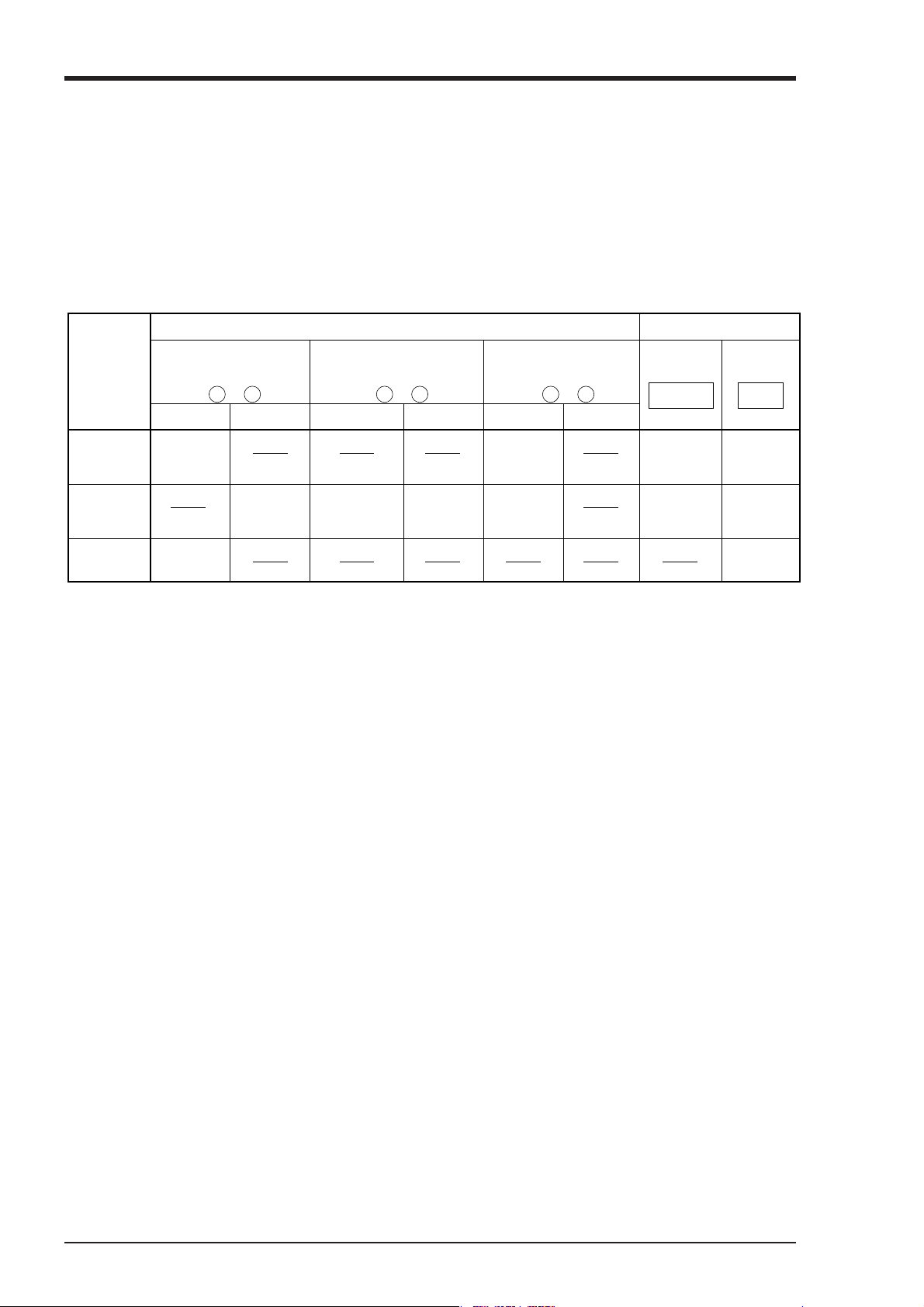
Remote control
Recording start
(across terminals
11 21
− )
Chart speed change
(across terminals
12 22
− )
Data print-out
(across terminals
− )
ON OFF ON OFF ON OFF
While
recording
is stopped
During
recording
List print
out
Recording
starts
Recording
starts
Recording
stops
Remote
mode chart
speed
Normal
operation
chart speed
List print-
out starts
List print-
out starts
(3) Caution on connection of input signal through barrier
• Thermocouple input and resistance bulb input.
Perform "Calibration of measured value" with the input connected to the barrier recorder because
the barrier internal resistance is added and causes an error in the measured value.
For the calibration method, refer to Item 9.4.
13 23
Front panel swich
RECORD
Recording
starts
Recording
stops
List print-
out starts
List print-
out starts
List print-
out stops
LIST
4 - 6 INP-TN3PHCV-E
Page 20
5. SET-UP
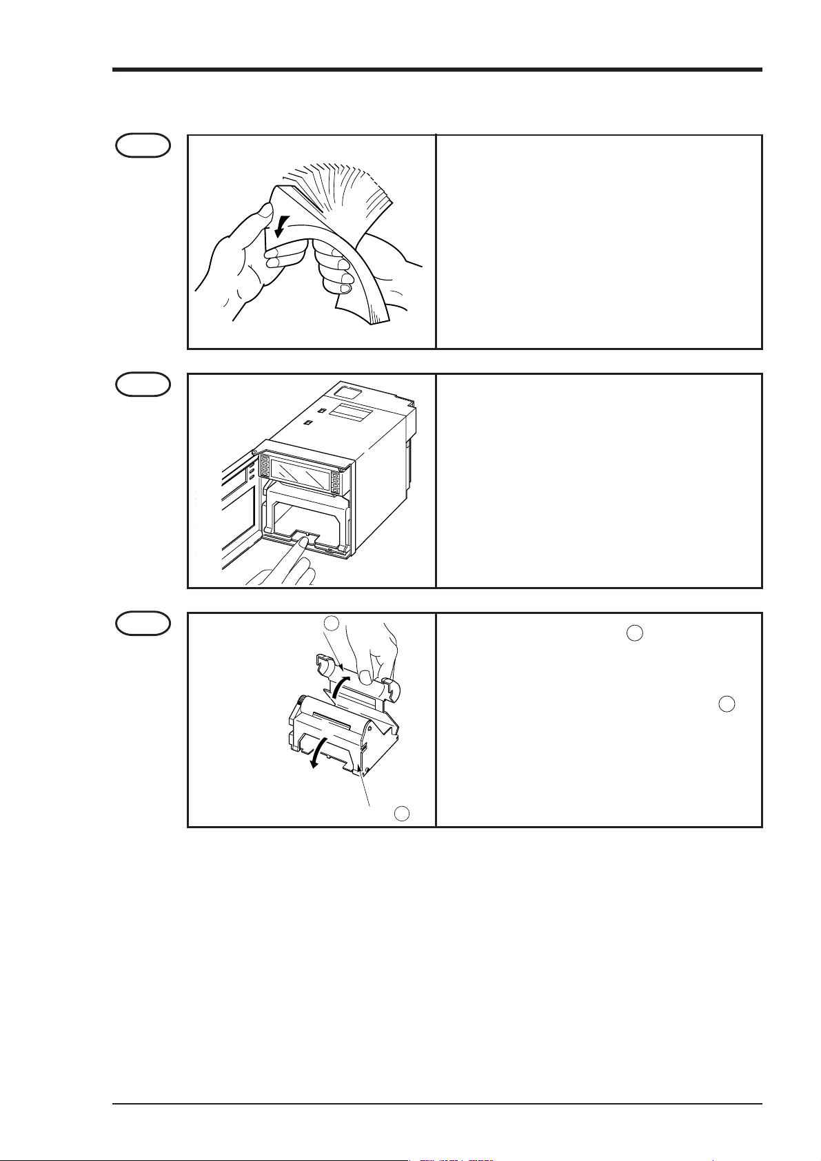
5.1 Loading Chart Paper
Step 1
Step 2
Prepare chart paper.
Loosen both ends of the chart paper thoroughly to
prevent sheets from being fed together.
Open the front door and press down the paper feed
unit drawout lever.
The paper feed unit will be drawn out.
Step 3
Chart paper retainer B
Chart paper retainer A
Hold the chart paper retainer B and open it backward.
Also, hold and open the chart paper retainer A .
5 - 1INP-TN3PHCV-E
Page 21
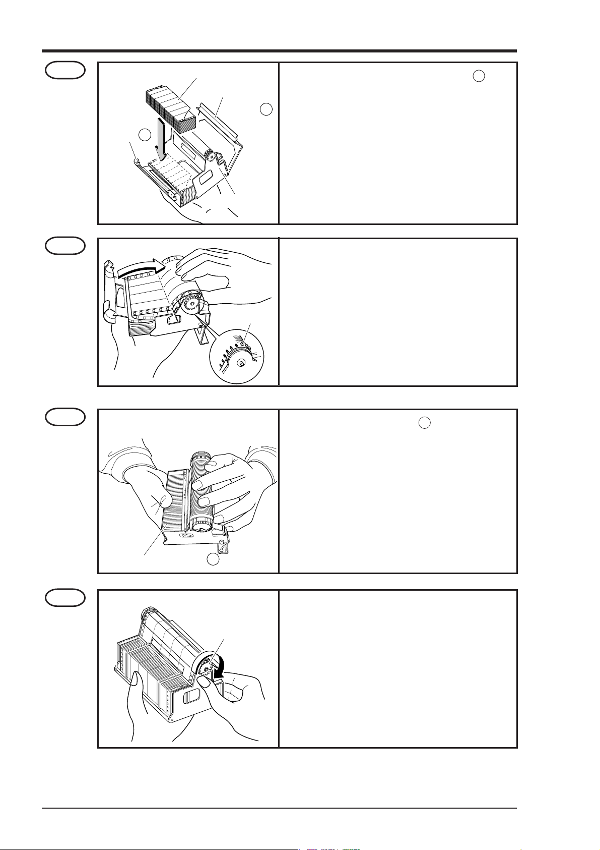
Step 4
Chart paper
retainter B
Chart paper
Paper feed unit
Chart paper
retainter A
Set chart paper in the chart paper retainer B as
illustrated.
Step 5
Step 6
Align the perforations of the chart paper with the
pins.
Pin
Close the chart paper retainer B .
(The chart paper is set vertically).
Chart paper retainter B
Step 7
Turn clockwise the gear of the roller unit with hand
and check that the chart paper shifts forward.
Gear
5 - 2 INP-TN3PHCV-E
Page 22
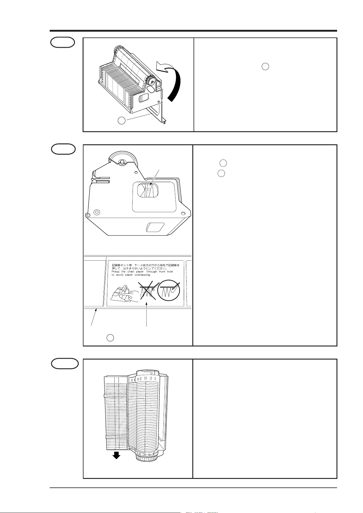
Step 8
Transfer the chart paper that has been forwarded
into the storage of the paper feed unit. Then close
the chart paper retainer A .
Chart paper
retainter A
Step 9
Check the chart paper
through this hole.
As shown by the caution display on the chart paper
retainer B , if paper is caught in the chart paper
retainer B , paper jam may result.
As shown by the figure at left, check through the
holes on the left and the right side of the paper feed
unit that the chart paper is not caught in the retainer.
Step 10
Chart paper
retainter B
Side provided with long holes
Gather the
chart paper
Caution in setting
a chart paper
The chart paper is provided with long holes and short
holes. Gather the chart paper in the storage to the
side provided with short holes as illustrated on the
left.
Side provided
with short holes
5 - 3INP-TN3PHCV-E
Page 23
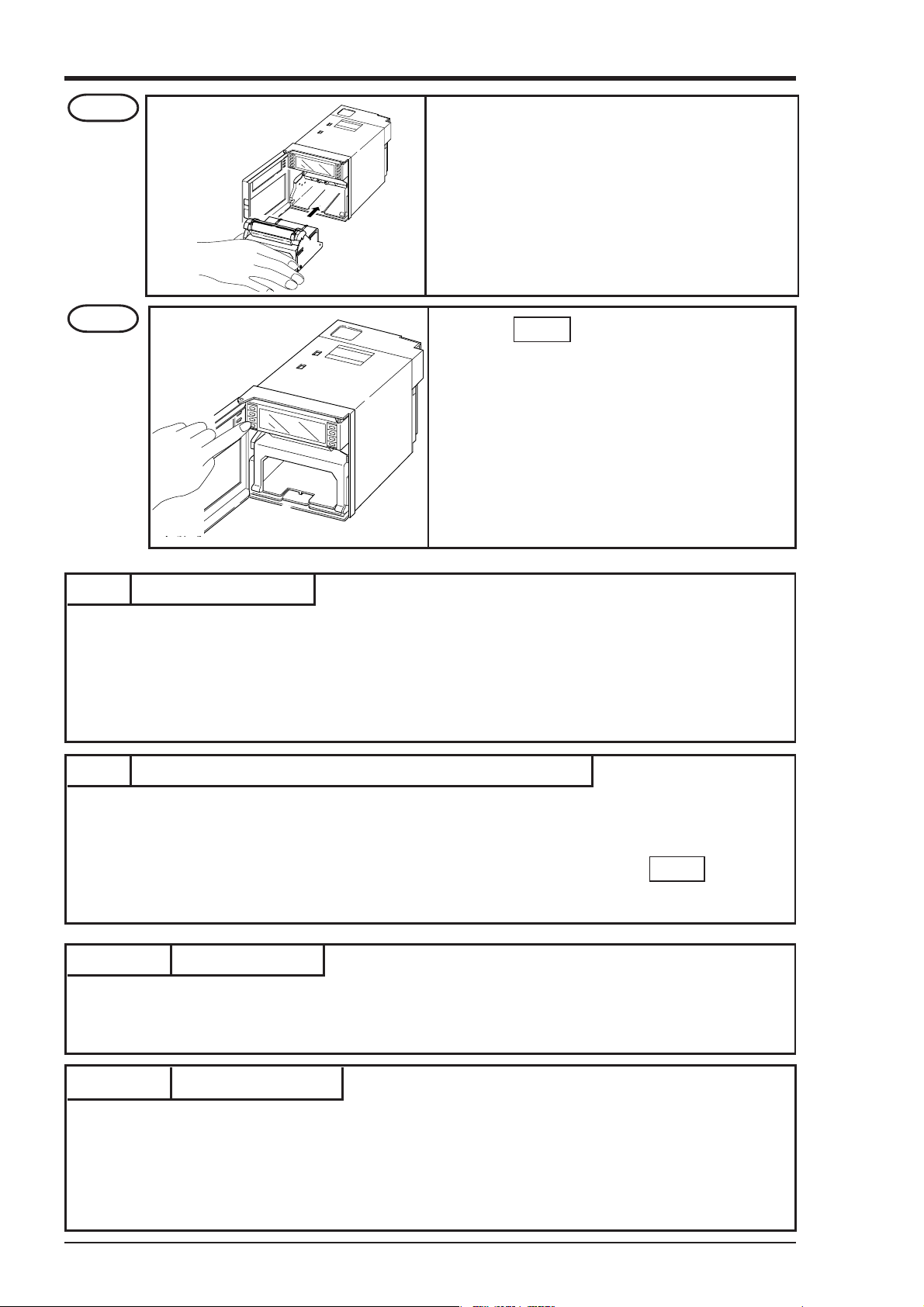
Step 11
Mount the paper feed unit in the recorder. At this
time, check that it is properly locked in position.
Step 12
Note 1 Selection of chart paper
The chart paper greatly affects the quality of the printed recording and it is also related to problems such
as paper jamming, etc.
Please be sure to use the pure-quality chart paper specified us.
Chart paper type : PEX00DL1-5000B (50 equal divisions, no time lines)
Press the FEED key and check that the chart
paper is fed out smoothly.
(Feed out about 2 folds of paper.)
<If the paper is not fed out smoothly, go through
the procedure from Step 2 again.>
Note 2 Use of the recorder after it has been left unused for a long time
If the recorder is left unused for a long time with chart paper still in the main unit, the paper 'packs down'
and if the recorder is used straightway there can be problems of paper jamming, etc.
If you use the equipment after it has been left unused for a long time, first press the FEED key to feed
out 2 to 3 folds of the paper.
Reference 1 Chart paper length
The chart paper is approximately 15m long. This permits about 31 days continuous print-out at a paper
feed speed of 20mm/h.
Reference 2 Chart paper end mark
The amount of chart paper remaining is indicated by digits (units : 10cm) on the right-hand side of the
paper. When there is only a small amount left, red letters appear on the right-hand edge.
If the recording paper runs out completely, a recording paper end indicator displays 'Chart end' in the
display section and recording automatically stops.
5 - 4 INP-TN3PHCV-E
Page 24
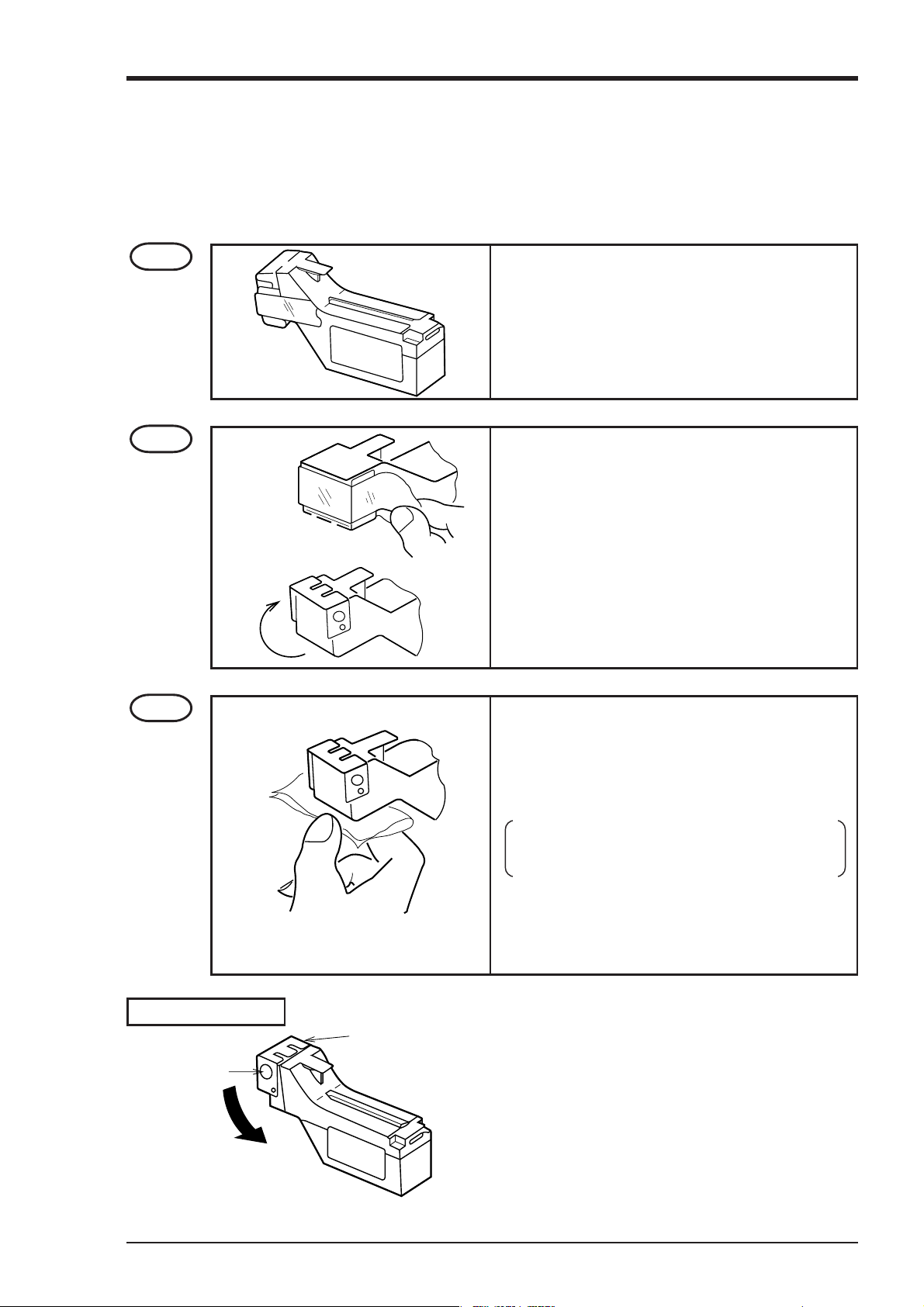
5.2 Recording head installation (replacement)
The recording head is a combination of a head and ink.
When ink is used out or trouble arises with the head, it can easily be replaced.
Use the recording head carefully observing the “Caution” noted in the later paragraph.
Step 1
Step 2
Get the recording head ready by taking it out of its
aluminium pack.
Tear the tape.
Open the cap by turning it in the direction indicated
by the arrow.
(If the head is not going to be used for a long time,
close the cap back in its original position.)
The cap is integral with the head unit. Turn it about
180° until it stops against the top of the head.
Step 3
How to close the cap
Stopper
• Lightly press the nozzle surface (the surface from
which ink is discharge). Make sure that the cloth
is properly impregnated with the 4 colors blue,
red, yellow and black.
First press the cloth against the surface for 2 to
3 second; if the 4 colors ooze out, it is OK.
Note) Do not use any cloth other than the supplied
one. Also, do not rub the nozzle with the
cloth.
Cap
• Turn the cap in the direction indicated by the arrow and press it firmly until it is retained by the
stopper.
• Ink may leak out if the cap is not properly in place.
5 - 5INP-TN3PHCV-E
Page 25
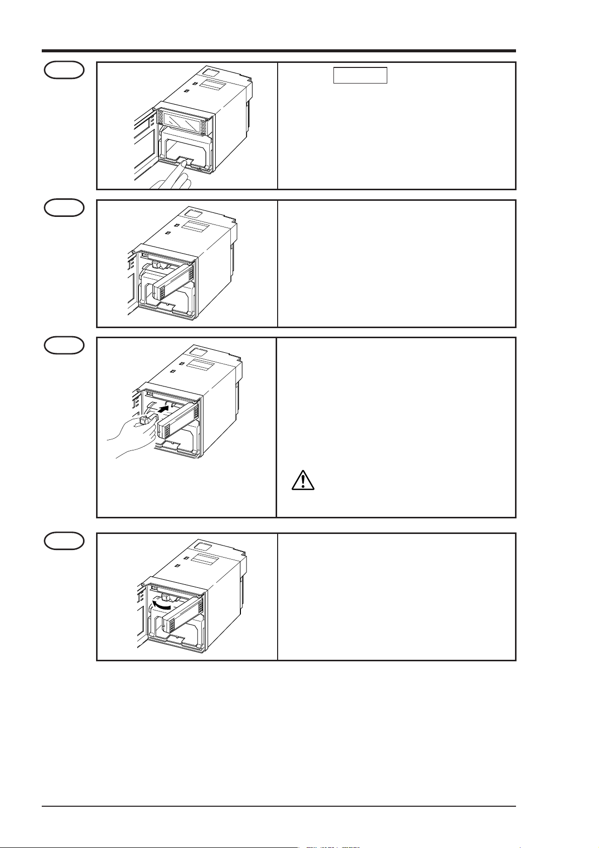
Step 4
• Press the RECORD key. Operate the recorder
after it has been set in recording stop mode.
• Open the front door and press down the paper
feed unit drawout lever.
The paper feed unit will be drawn out.
Step 5
Step 6
Hold the left end of the indicator and pull it forward.
The indicator will turn 90°.
• Hold the recording head horizontal, line it up with
the carriage in the main unit slide it in slowly
and press it firmly until it does not go in any further.
• Take care not to bang the nozzle surface of the
head. Also, avoid touching the nozzle surface with
your hand.
Do not touch the connector at the rear
of the carriage to avoid the risk of mi-
CAUTION
nor electric shocks.
Step 7
Set the indicator in its original position.
5 - 6 INP-TN3PHCV-E
Page 26
Step 8
The above completes installation of the recording head.
The recording head is a consumable part. Replace it with a new one when the ink it contains is
used up.
• Set the paper feed unit in its original position.
Recording head replacement
Draw out the recording head in the manner that is opposite to what is described in Step 6 of the
recording head setting procedure, and replace it with a new recording head.
Always carry out the following procedure after replacing a recording head.
(1) Setting the ink monitor
Perform the following keying actions in order to get correct performance of the ink dry-up warningdetection function.
As in “Clearing the ink monitor” of Section 7.16, press the SELECT key to give an “INK
MONITOR CLEAR” display
INK MONITOR CLEAR
NO
∧
Press the ∧ key to change the flickering “NO” to “YES”.
Next, press ENTRY key.
This completes the setting.
↓
Press the DISPLAY key to return to a data display.
INK MONITOR CLEAR
YES
(2) Test pattern print-out
Print out a test pattern to check that normal recording is possible. See Section 6.3 for the way of
printing out a test pattern.
(3) Adjustment of analog trend recording positions
Referring to Section 9.2, readjust the zero and span on the recording paper.
5 - 7INP-TN3PHCV-E
Page 27
Precautions in handling recording heads
Note 1 If recording is halted and the recorder is not used for a long time
Carry out the following in order to prevent jamming and drying-up of the ink.
Remove the recording head from the main unit, make absolutely sure the cap is closed properly and store the head in a cool, dark place (average temperature 5 to 30°C).
If the head is left installed in the recorder:
Do not switch off the power to the recorder and do not close the cap.
* Periodically, there is an automatic discharge of ink to prevent drying-up.
Leave the recording paper in place in the recorder.
If it is not possible to keep the power switched on, make sure that the cap is closed.
Draw out the paper feed unit using the recording head setting method Step 4 and Step 5 .
Open the indicator and tighten the cap.
Note 2 At the start of use of a recording head
If you are starting to use a new recording head or if the recorder has been left unused for a long time,
always wipe the head's nozzle surface lightly with the accessory cloth and check that the 4 colours
black, blue, red and yellow ooze out properly into the cloth. (See Section 5.2.)
Also, after normal recording is possible. See Section 6.3 for the way of printing out a test pattern.
When the working environment is 15°C or less, perform print-out of "test pattern" after period of several minutes has elapsed since the recording head was mounted. (The recording head has a built-in
heater.)
Note 3 Handling recording heads
•Do not knock or shake recording heads as this can cause faults.
• The inks are not harmful but they are very difficult to remove if they adhere to the skin or to clothes,
so handle heads carefully in order to avoid staining. Also, do not disassemble them.
• If, by accident, it happens that ink gets into your eyes, wash thoroughly with water as an emergency
measure and then immediately consult a specialist doctor.
• When the ink is used out, dispose of its recording head as incombustible object.
• This product is intended to be used where are not dusty.
• Be sure to start to use the product soon after opening package. (Be sure to finish using this within 1
year after opening)
5 - 8 INP-TN3PHCV-E
Page 28
Note 4 Storage of recording heads
• When they are delivered, recording heads are in aluminium packs.
If you are not going to use a head straight-away, leave it sealed and store it in a cool, dark place with
an average temperature of 5 to 30°C.
• Storage period: 1year and half after purchased
Note 5 Shipping of recording head
• Do not ship the unit recording head after the aluminum pack was opened up. If it is necessary to ship
the unit recording head under avoidable circumstances, be sure to close the cap, and ship it as contained in a boxboard in the state where vibration and impack are eased using cushioning materials.
• Always close the cap if you are transporting a head while it is still installed in the recorder main unit.
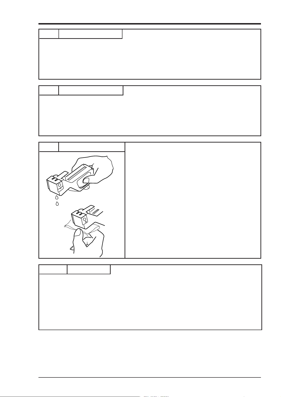
Note 6 If the ink is not sprayed.
①Hold the recording head with turning the nozzle surface
downward and push the side strong till spilling two drops.
②Absorb the standing ink on the nozzle surface with the cloth
attached.
③Hold the cloth to the nozzle surface again to find all colours
flowed onto cloth.
When ink does not come out, repeat the above operation
( ① through ③ ).
* When working environment is 15°C or less, perform
print-out of "record" or "test pattern" after a period or
several minutes has elapsed since the recording head was
mounted. (The recording head has a built-in heater.)
Reference Ink consumption
When recording at 20mm/h of chart paper feed speed and a given input, the consumption of ink is as
shown below , though it depends on operating conditions.
About 1 year ---------- 1, 2, 3 continuous recording or 6 intermittent recording
About 6 months ------ 6 continuous recording
Alarm of ink consumption is displayed and printed by ink consumption detecting function.
(See Section 11.12 for an example of print-out.)
5 - 9INP-TN3PHCV-E
Page 29
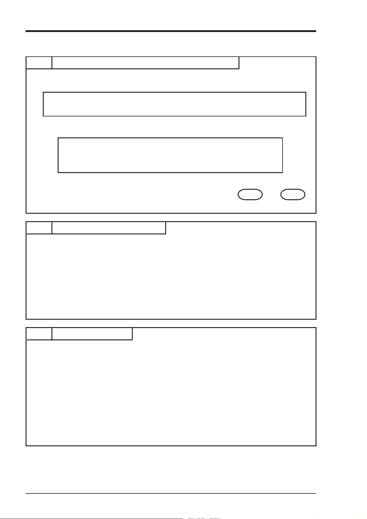
5.3 Changing the type of input signals
This recorder is a multi-input type which permits the input for any channel to be changed to thermocouple, resistance bulb or DC voltage input.
Follow the procedure described below if you with to change the type of input signals subsequent to
purchase.
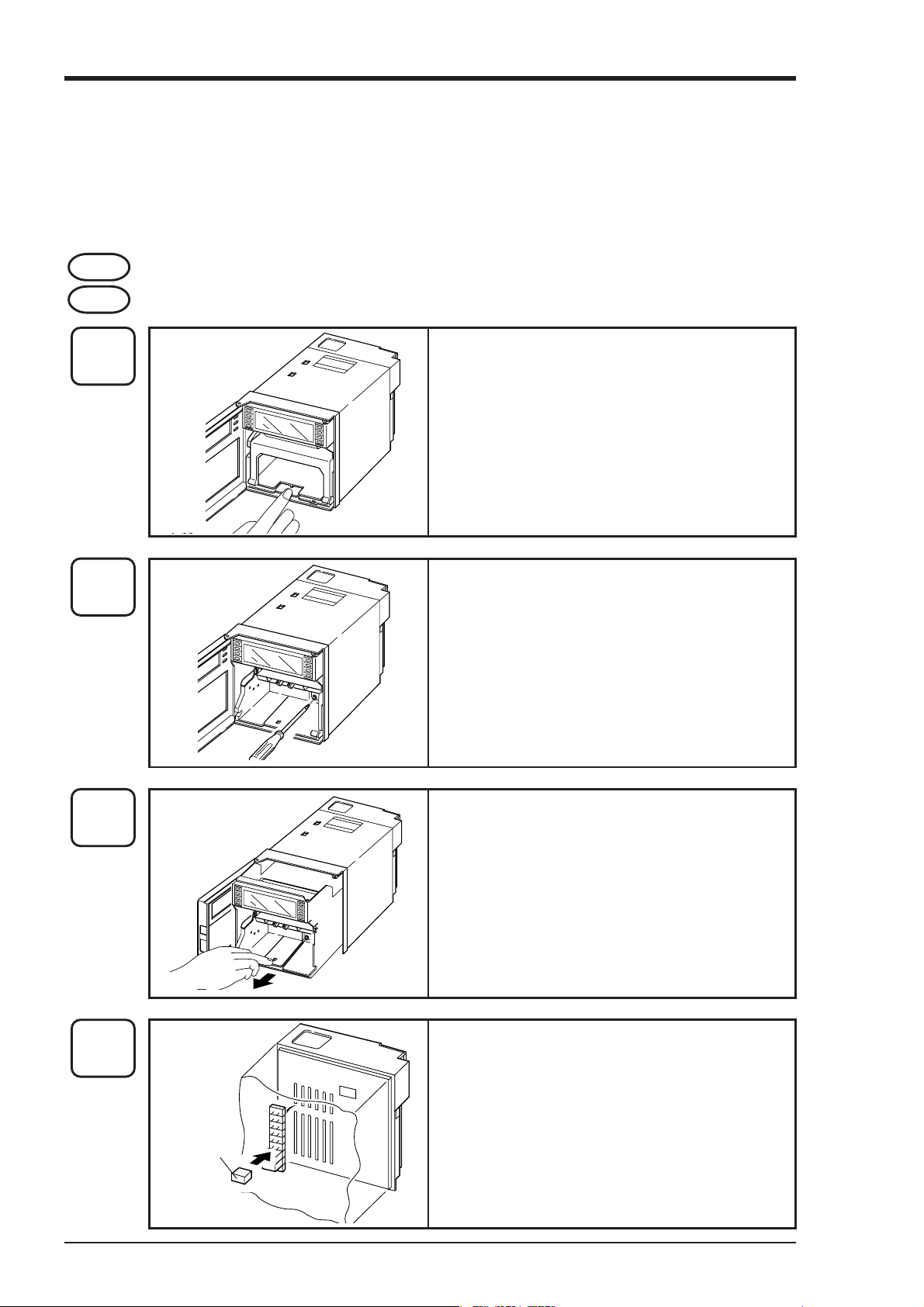
Step 1 Turn off the power.
Step 2 Open the front flap and remove the main unit in the manner shown in the drawings below.
Step
2 - 1
Step
2 - 2
Open the front door and press down the paper feed
unit drawout lever.
The paper feed unit will be drawn out.
Loosen the lock screw (M4) in the unit with a phillips
driver.
Step
2 - 3
Step
2 - 4
Input signal
setting pins
Hold the side or bottom of the frame and pull the
unit forcedly to remove it from the case. It can be
removed easily when the door is opened by about
90°.
Change the setting of each channel pin on the printed
circuit board in the unit.
(See the next page for changing the position of pin.)
* To remove or attach the pins, use pincette or pli-
ers.
5 - 10 INP-TN3PHCV-E
Page 30
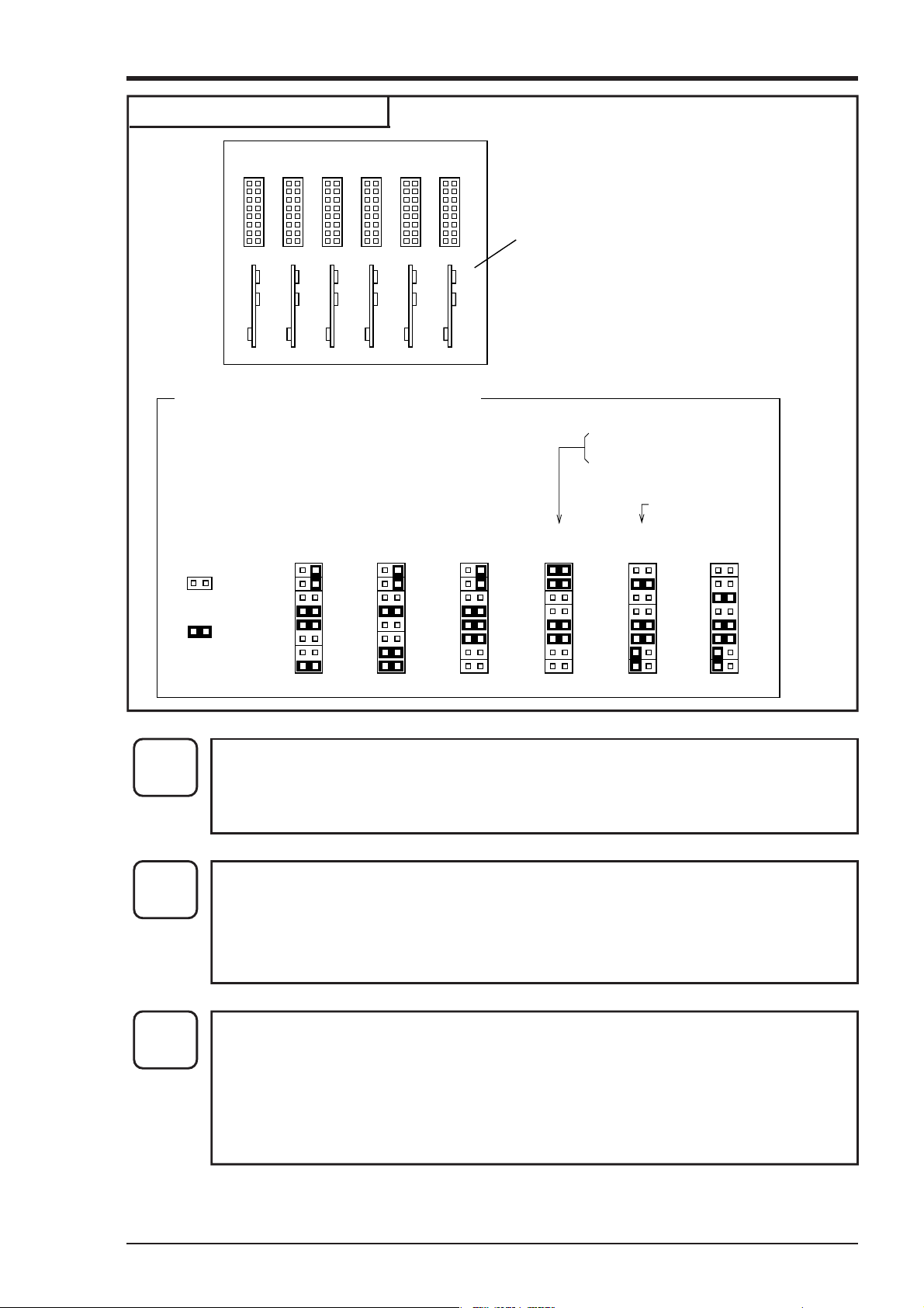
Method of changing pin positions
CH1 CH2 CH3 CH4 CH5 CH6
Pin positions for different types of inputs
Large PC board installed in depth of the case
• Pin setting is required in correspondence with types of
inputs for each channel.
• The set position is as shown below.
MAX.
±50mV
Step
2 - 5
Thermo-
couple
OPEN
SHORT
• After completing the change, push the main unit back into its original place and fix it with
the left and right lock screws.
• Push in the paper feed until it is set as before.
Resistance
bulb
MAX.
±500mV
4 to 20mA DC input
10 to 50mA DC input
1 to 5V DC input
MAX.
±5V
MAX.
±50V
Step
2 - 6
Step
2 - 7
• Change the input terminal wiring to make it correspond to the new input signal type.
• For DC voltage input, provide the input terminals with shunt resistors.
Example: In the case of 4 to 20mA DC input, fit the separately sold shunt resistors (10Ω
and set to ±500mV range input pin positions.
Refer to Section 7.8 and carry out front-panel keyboard operations in order to change setting
in correspondence to changed types of input signals.
[Note] DC current input is converted into voltage by shunt resistor (10Ω):
In 4 to 20mA DC : 40 to 200mV DC range
In 10 to 50mA DC :100 to 500mV DC range
5 - 11INP-TN3PHCV-E
Page 31

6. OPERATION AND ACTIONS
6.1 Before running the equipment:
Check the following points before starting operation.
1
2
3
Setting the chart paper and recording head
① Setting the chart paper ..................................................................................... See Section 5.1
② Setting the recording head ............................................................................... See Section 5.2
Wiring
① Input terminals .................................................................................................
② Alarm terminals (option) ................................................................................. See Section 4.2
③ Power and earth terminals ...............................................................................
}
Conformity of input connection to recording channel
① Code symbols .................................................................................................. See Section 1.3
② Change and settingo type of input signal......................................................... See Section 5.3
6 - 1INP-TN3PHCV-E
Page 32

6.2 Power switch-on and states
(1) Open the front door. Then hold the left end of the indicator and turn it forward.
(2) The power supply switch is at the above left; switch it on.
1) Initial switch-on of power
↓
The recording head moves slowly toward the right end (100%).
↓
After detecting 100%, the recording head moves to the center and stops ant that position.
↓
1 100℃
2) If the power is switched off while recording is stopped and switched on again.
(The state becomes “Recording stopped”)
3) If the power is switched off during recording operation and switched on again.
(The state becomes “Recording in progress”)
The input data and Tag No. are displayed in the display section.
(No recording takes place.)
Recording in progress
↓
Power supply cut off
↓
Display disappears Recording stops
↓
Power turned on again
↓
The recording head moves slowly tooward the right end (100%).
↓
After detecting 100%, the recording head moves to the center and then the right end, and it stops
at that position.
↓
1 100℃
Rec. ON
The input data is displayed in the display section and recording restarts.
6 - 2 INP-TN3PHCV-E
Page 33

6.3 Test pattern print-out
(1) Open the front flap, switch the power supply switch on the press the SELECT key.
(2) Pressing the SELECT key several more times results in the following display.
LIST=1
PARAMETER LIST
(3) Press the ∧ key twice; this gives the following display.
LIST=1
TEST PATTERN
(4) When the ENTRY key is pressed, the following test pattern is printed out.
Yellow Red Orange Blue Green Purple Black
• Check that there is a complete recording in each colour.
If the colours do not come out or are blurred, follow the procedure of Section 5.2 to clean the
recording head nozzle surface.
6.4 Actions during operation
(1) Stopping and starting recording operation ( RECORD key)
•Stopping the recording is possible at anytime during operation.
• Recording is alternately started and stopped each time the RECORD key is pressed.
6 315℃
Rec. ON
During recording operation When recording is stopped
(2) Digital print-out (instantaneous values) ( LIST key)
Example of record
• Measured values can be printed out any time during operation.
• Pressing the LIST key results in a digital print of the time at which the key was pressed and the
measured values and units of all the channels at that time.
• Analog trend recording is stopped during digital printing.
• Completion of digital print-out is followed by a return to analog recording.
• To stop printing during operation, press the LIST key. Analog trend recording is started again.
• Channels which are skipped are printed with the sign “–” (lateral line).
6 315℃
6 - 3INP-TN3PHCV-E
Page 34

(3) Chart paper fast feed ( FEED key)
To effect fast feed regardless of recording, press the FEED key.
•
• The speed is 3mm/s during the first second that the key is held depressed and goes to 8mm/sec
after the elapse of 1 second.
•
When the FEED key is released, there is a return to the set speed.
(4) Changing the display mode ( DISPLAY key)
• Display modes can be selected at any time pressing the DISPLAY key during operation.
There are the following changes in the display mode each time the DISPLAY key is pressed.
•
Measured values
Multipoint
sequential display
DISPLAY
Measured values
One-point
continous display
DISPLAY
Measured values
Multipoint
display
DISPLAY
Time display
1 150℃
Record ON
One-point continous display mark
6* 315℃
Record ON
Ch1 Ch2 Ch3
0.001 25.00 50.00
-3.45 -7.00 -11.00
Ch4 Ch5 Ch6
90 10/30 11:30
Record ON
There is sequential
display starting from
ch1.
Only specified
channel is displayed.
To change channels, get a
channel No. by pressing
the ∨ , ∧ key.
(E.g., channel 6)
Channel 1 to 6 are
display simultaneously.
The current time is
displayed.
DISPLAY
Note) No Record ON is displayed when recording is stopped.
6 - 4 INP-TN3PHCV-E
Page 35

6.5 Displays and print-outs on detection (cancellation) of alarms
(1) If an alarm is detected the display section gives a display as follows.
Example of alarm display
Example: Upper section Ch 2 measured
2 123.5℃
Ch6 ALARM H ALM1
(This display continues until it is cancelled.)
(2) When an alarm detected and cancelled, the relevant details are printed on the right-hand side of the
chart paper.
On detection: The time of detection, channel No., type of alarm, relay No.
...............................................Print-out color: Red
On cancellation: The time of cancellation, channel No., relay No.
............................................Print-out color: Black
Example of alarm print-out
value
Lower section Alarm in Ch 6
H alarm, relay No. 1
2Channel 1 No. 1 H alarm release
Relay No. 1
Release time: 14:58
1Channel 1 No. 1 H alarm generation
Relay No. 1
Generating time: 14:57
(3) If an alarm is detected or a cancellation is made during data print-out or list print-out, the alarm
print-out takes place after completion of the data or list print-out.
(4) Up to a maximum of 30 alarm detection cancellation information can be stored and sequentially
printed out, but if the storage capacity is exceeded because of a large number of detections/cancellations in a short time, information in the overflow portion is discarded and cannot be printed out.
6.6 Displays and print-outs on occurrence of burnt-out
(1) If a thermocouple or resistance bulb wire breaks, the relevant details are indicated in a display
Example of burn-out display
6 BURN - OUT
Rec. ON
0.10.010.001
Burnout
-0.01-0.001
Note: The trend record is switched to the 100% side.
(2) When alarm is generated or released, its data is printed on the right side of chart paper.
(print color: red)
Example: Burn-out in Ch 6
Multipoint display
Example of burn-out print-out
1 BURN - OUT 11:52
Time of occurrence : 11. 52
Channel No. : 1
6 - 5INP-TN3PHCV-E
Page 36

6.7 Over-range, under-range display and abnormal input display
In all cases, for thermocouples, resistance bulbs and DC voltage input, there is a reference range for
input signals. If input is outside preset range an 'Over' or 'Under' display is given.
Example of over/under display
2 OVER ℃
Rec. ON
5 UNDER ℃
Rec. ON
When voltage input is applied and the input signal cable breaks down or an over/under voltage is
inputted, it is displayed as an abnormal input.
Example of abnormal input display
3 ERROR
Rec. ON
0.0 OVER
100.0
(Multipoint display)
0.0 ERROR
100.0
6.8 Display and record when chart paper runs out ("Chart End" display)
When chart paper is used out, the following is displayed and the recording stops automatically.
But display of measured value and alarm monitoring are continued.
6 123.5℃
Chart End
6.9 Display and record when the recording head ink is low ("Ink Out" display)
(1) A display as follows is given on the chart paper when the amount of remaining ink is low.
Ink End' is displayed in the display section.
Example
6 123.5℃
Ink Out
(2) 'Ink Empty' is printed on the right-hand side of the chart paper.
< Print-out color : The color of the ink whose remaining quantity is low >
Note) The sign "Ink End" is displayed when the ink left in the recorder reaches less than 10%, but
recording continues for a while after "Ink End" is displayed. Use a new recording head.
(When ink is used out, recording and printing operation is interrupted immediately)
Under stage: Measured value of Ch 6
Lower stage: Ink end
6 - 6 INP-TN3PHCV-E
Page 37

6.10 Display when data backup batteries need to be replaced ("Battery End" display)
When the voltage of back-up batteries becomes low, a display indicating that they need to be replaced
is given.
'Battery End' is displayed in the display section.
Example
6 123.5℃
Battery End
Replace the batteries promptly when a 'Battery End' display appears page 8-3.
Under stage: Measured value of Ch 6
Lower stage: Battery end
6.11 Display of fault in recording head carriage ("Carriage Alarm" display)
If a fault in the recording head carriage occurs and the recording head can no longer function normally,
a fault display is given and the recording operation stops.
Example
6 123.5℃
Carriage Alarm
When the sign "Carrier Failure" is displayed, turn OFF the power and check the following points.
(1) Is foreign matter adhering to the recording head carrier shaft ?
(2) Is the wire that drives the recording head broken or slack ?
(3) Has the recording paper lifted up and come into contact with the recording head ?
(4) Is the recording head set in place correctly ?
After eliminating the cause of the fault, switch on the power supply of the main unit.
Under stage: Measured value of Ch 6
Lower stage: Carriage failure
6.12 Order of priority of state displays
If the items noted below occur simultaneously, the corresponding displays are given in the indicated
order.
1. Chart end
2. Carriage alarm
3. Ink end
4. Battery end
5. Alarm
Note: When the state displays 1 and 2 above are given, the SELECT key is inoperative.
However, the DISPLAY and FEED keys are operative.
6 - 7INP-TN3PHCV-E
Page 38

7. SETTING AND CHECKING PARAMETERS
7.1 Setting and Checking
① The parameters at the time of shipment are as indicated in the table below. Recorder operations
(displays, analog trend recording) can be effected simply by switching the power on without making any adjustments, but you can set the parameters you require.
② The record ranges are multirange and it is necessary to set the required ranges.
③ Alarms, Tag Nos., Message, scaling, square root extracting and subtract calculation, daily report
and totalize functions are not set. Please set these if they are required. Input filters are set to 3
seconds.
④ After setting up parameter, it is recommended to print out parameter list and retain parameter in
order to find out setting contents later. (refer to the Item 7.11regarding printing out parameter list.)
Note) If you set parameters, always do so after setting chart paper in place.
If chart paper is not installed, the SELECT key is inoperative.
7 - 1INP-TN3PHCV-E
Page 39

(1) Values of parameters at the time of shipment (initial values)
Parameter name
Pass code
Main chart speed
Sub-chart speed
(option)
Alarms
Recording mode
Record range
State at time of shipment
(initial values)
(Cancelled)
20mm/h
20mm/h
No. 1 to 4 : No
Set value : 0
ALM : 0
Trend recording
Periodic print-out : ON
Scale print-out : ON
Recording format :
standard
Thermocouple system:
0 to 1200°C, K
Resistance bulb system:
0 to 500°C, Pt
DC voltage system:
–5 to +5V DC
Remarks
Setting range : 0 to 9999
Setting range : 5 to 1500mm/h
Setting range : 5 to 1500mm/h
Changed by external contact input
4 kinds and 4 points, L, H, RH and RL,
are available for each channel (relay
output: option).
Trend recording/logging recording
selection
Periodic digital print-out on/off selection
Fied interval scale lines, digital, units
printout selection
Standard, auto-range recording, zoom
records, zone recording selection
Specifiation of record range
Method of setting, chekcing
Section 7.3
Section 7.4
Section 7.4
Section 7.5
Section 7.6
Section 7.7
Input selection
TAG No.
Message print
List print-out
Thermocouple:
K thermocouples, °C
Resistance bulb:
Pt100, °C
DC voltage : V
Input filter : 3 seconds
Scaling : OFF
Rooter : OFF
Subtract calculation : OFF
Computation : OFF
Blank
Blank
Print position : 0.0mm
Print timing : Manual
Input type specification,
°C, °F, specification
mV, V specification
Setting range : 0 to 900 seconds
DC voltage input scaling can be set
(working values, units)
DC voltage input rooter (square root
extractor ) can be specified
Recording of differences between
channels can be specified
Up to 8 alphanumeric characters
10-message, alphanumeric :
Within 16 characters
Parameter list print-out, scale print-out,
test pattern print-out, daily report,
totaling list
Skip/copy
setting
Section 7.8
Section 7.9
Section 7.10
Section 7.11
7 - 2 INP-TN3PHCV-E
Page 40

Parameter name
State at time of shipment
(initial values)
Remarks
Method of setting, chekcing
Daily report
Totalize
RS-485
transmission
(option)
Time setting
Ink monitor
clear
Recoding paper
illumination
lamp (option)
Function : OFF
Automatic print-out :
Start time : 00:00
End time : 00:00
Function : OFF
Automatic print-out :
Start time : 00:00
End time : 00:00
Station No. : 1
Baud rate : 19200bps
Stop bit : 1
Parity : odd
Current time setting
NO
ON
Daily report function on/off selection,
start time selection
Daily report list automatic print-out on/
off selection
ON
Daily report operation on/off setting for
each channel
Totalize function on/off selection, start
time selection
Totalize list automatic print-out on/off
ON
selection
Totalize operation on/off setting for
each channel
Specified if there is connection with
parent CPU.
Display in the order –– Year –– Month
–– Day –– Hours –– Minutes
Setting of ink end warning-detection
function. Always set to clear (YES)
after recording head replacement.
Set to "OFF" to turn out the recording
paper illumination lamp.
Section 7.12
Section 7.13
Section 7.14
Section 7.16
Section 7.16
Section 7.17
7 - 3INP-TN3PHCV-E
Page 41

7.2 Outline of Procedure for Setting Parameters
Data display mode key
DISPLAY
SELDISP
Pass code
If pass code specification
is 0, this display is skipped.
SEL
Main chart speed
Section 7.4
SEL
Sub-chart speed <Option>
Section 7.4
SEL
Alarm
Section 7.5
SEL
ENT
Recording mode
SEL
Record range
Logging
Trand
Section 7.6
Section 7.7
ENT
=Description of keys=
●
SEL
: key
●
ENT
: key
●
DISPLAY
●
∧
●
To return to the beginning of parameter settings, press the
key once and then press the key.
Logging interval
Periodic print-out
Scale print-out
SELECT
Whatever the current state, operation moves to the next
mode when this key is pressed.
ENTRY
If this is pressed when data is to be registered following
specification or when registration is not needed, there is a
move to display of the next set item.
:Whatever the current state, there is a return to the data
display mode when this key is pressed.
∨
:These serve for specification and selection of data.
SELECT
ENT
Record format
ENT
Standard
Auto-range
Zone
Zoom
DISPLAY
SEL
Input selection
SEL
TAG No.
SEL
To next page (a)
Section 7.8
Input type unit
Input filter
Section
7.9
ENT
In case of
thermocouples,
resistance bulbs
When OFFDC voltage
Scaling ON/OFF
ENT
Measure range
ENT
Rooter
ENT
Engineering range
ENT
Units
ENT
Subtraction
ENT
7 - 4 INP-TN3PHCV-E
Page 42

(a)(b)
SEL
Message print
SEL
List print-out
SEL
Daily report function
SEL
Totaraize function
SEL
Transmission
SEL
Time setting
Section 7.10
Parameter list
Scale print-out
Test pattern
Daily reort list
Totalize list
Message print
Section
7.12
Section 7.13
<Option>
Section 7.14
Section 7.15
Section 7.11
Section 9 Application
SEL
Ink monitor clear
SEL SEL
Illumination lamp
ON/OFF
SEL
Pass code
specification
SEL
FEED+SEL
Section 7.16
<Option>
Section 7.17
Section 7.3
Back lash calibration
Record zero-span
calibration
SEL
Alarm lach
SEL
PV shift
SEL
Unit preparation
SEL
Record error
external output
DISPLAY
To data displaymode
7 - 5INP-TN3PHCV-E
Page 43

7.3 Pass code setting
Explanation
If the pass code is set to a value other than 0, it is necessary to enter the correct pass code before
changing parameter setting pass code. A numerical value is specified on the screen by means of the
∧ and ∨ keys and is input by the ENT key. If this value is the same as the previously set pass
code, there is a move to a display of the next parameter.
If the pass code is incorrectly specified, the keys are locked as follows.
Preset pass code < 5000
Only the list display is given and it is not possible to change parameter setting.
Preset pass code ≧ 5000
The list display is given, but list print-out is inhibited.
Furthermore, RECORD , LIST , and FEED keys on the front panel are locked.
At the time of shipment, the pass code is set to 0 and the key lock is released.
If the pass code is 0, the pass code display is skipped.
Example Setting of the pass code
Key actuation
SEL
∧ ∨
ENT
DISP
SEL
∧
Explanation
Press the SEL key several times to bring up
the pass code specification display.
Press the ∧ ∨ key to specify the value you
want for the pass code (specification range: 1 to
9999).
Press the ENT key to register the value. When
it has been registered, there is a move to the next
parameter.
Press the DISP key to go to the data display
mode.
Press the SEL key to bring up the pass code
input screen.
Press the ∧ key to give the value of the pass
code that has been specified.
Display
PRESET PASS CODE
□□□□
PRESET PASS CODE
□□□□
MAIN CHART SPEED
□□□□ mm/h
ch1 123.4℃
PASS CODE =?
□ 0
PASS CODE =?
ENT
Press the ENT key to effect registration.
Note: If the value input at this time is differ-
ent from the pass code that has already
been specified, the list screen comes up
(key lock state).
In this case, it is not possible to clear the pass
code, so go through the process again from the
beginning and input the correct value.
If the value input is the same as the pass code
value, there is a move to the next parameter.
LIST=1
PARAMETER LIST
MAIN CHART SPEED
□□□□ mm/h
7 - 6 INP-TN3PHCV-E
Page 44

7.4 Setting the Chart Speed (main chart speed/sub-chart speed)
Explanation
•Main chart speed : This is the procedure fo rsetting the chart speed in normal operation.
The setting range is 5 to 1500mm/h (Can be set in 1mm/h steps.)
• If the case of a continuous recording type, if the chart speed is too fast, the result is dashed line
recording instead of continuous recording. (As a general criterion, 400mm/h or more)
• Please note that the following digital print-outs are not possible if the chart speed is 401mm/h or
more for continous recording or 51mm/h or more for dot recording.
"Periodic print-out", "Message print-out", "Scale print-out", "Alarm printout", "Parameter printout", "Ink Out print-out", "Burn-out".
However, a "Scale print-out", "Message print-out" can be made manually. See Section 7.11.
• On an intermittent recording type, if the chart paper feed speed is fast, it becomes difficult to read
recording due to increase in the space between break points. It is recommended that the recorder be
sued at a speed of 50mm/h or less.
• On a continuous recording type, the recording cycle varies with chart paper feed speed.
400
Sample time (sec.) =
Chart speed (mm/h)
(But not faster than 2 seconds.)
Example)
Chart speed (mm/h) 10 20 25 50 100 200 or more
Sample time (sec.) 40 20 16 8 4 2
• Sample time of intermittent recording type is fixed to 30 seconds.
Example Changing the normal chart speed of 25mm/h to 20mm/h.
Key actuation
SEL
∨
Press the SEL key twice to display the main
chart speed.
Press the ∨ key to set to "20".
Explanation
MAIN CHART SPEED
25 mm/h
MAIN CHART SPEED
20 mm/h
Display
ENT
Press the ENT key to effect registration.
There is a move to display of the next parameter.
SUB CHART SPEED
25 mm/h
7 - 7INP-TN3PHCV-E
Page 45

Explanation
• Sub-chart speed : This is the chart speed when its rate is controlled by an remote control signal.
The setting range is 5 to 1500mm/h. (Can be set in 1mm/h steps.)
The optional external control unit is necessary.
Example Changing the recording paper feed of speed 100mm/h to 150mm/h by an external control
signal (DI)
Key actuation
SEL
∧
ENT
Explanation
Press the SEL key 3 times to display the subchart speed.
Press the ∧ key to set to "150".
Press the ENT key to effect registration.
There is a move to display of the next parameter.
Display
SUB CHART SPEED
100 mm/h
SUB CHART SPEED
150 mm/h
ALARMCh1 HH=OFF
0
7 - 8 INP-TN3PHCV-E
Page 46

7.5 Setting Alarms
Explanation
• Channel : Setting of channel No. for object alarm.
• Alarm No. : Up to 4 points of alarm can be set per channel.
• Kind of alarm : 4 kinds, H, L, RL, RH (setting freely for each channel).
Alarm operation stoops at selection of No. (alarm display, print and alarm output operations are not available).
• Alarm setting value: Setting in industrial values (absolute alarm value)
• ALM : Setting of option alarm unit relay No. (no output at 1 to 6, 0)
Example Chang of alarm No. 1 of channel 1
L → H30°C → 80°C ALM→ 6
Key actuation
Explanation
Display
SEL
ENT
∧
ENT
∧
ENT
∧
ENT
Press the SEL key several times to give the
alarm display. (In cases where pass code = 0)
Select channel to be changed, and press the
∧ key.
Press the ∧ key to change "L" to "H".
Press the ENT key.
Press the ∧ key to change the set value from
"30°C" to "80°C" and press the ENT key.
Press the ∧ key to change the ALM No. from
"1" to "6" and press the ENT key to effect
registration.
When the ENT key is pressed, the
channel No. flashes and the setting is
completed.
Follow the same procedure for setting in
other channels.
ALARM Ch1 NO.1=L
30℃ ALM1
ALARM Ch1 NO.1=L
30℃ ALM1
ALARM Ch1 NO.1=H
30℃ ALM1
ALARM Ch1 NO.1=H
80℃ ALM1
ALARM Ch1 NO.1=H
80℃ ALM1
Note : RH, RL ……High/low limit alarm for variation rate.
Alarm is emmitted when variation rate per input exceeds the set value of each
alarm.
7 - 9INP-TN3PHCV-E
Page 47

7.6 Setting the recording mode
The following recording modes can be set in this section.
① Logging recording (logging)
② Periodic print-out
③ Scale print-out
④ Auto-range recording (auto-range)
⑤ Enlarged/reduced recording (zoom)
⑥ Zone recording (zone)
Setting procedure
RECORD MODE
Logging
∧
∨
RECORD MODE
Trend
ENT
PERIODICPVLIST=ON
SCALEPRINT =ON
ENT
ENT
LOGGING INTERVAL
30min
∧ ∨
Use the and keys to select the record format (standard, auto-range, zone, zoom).
RECORD FORMAT
NORMAL
ENT
∧ ∨
Startofrecording
REC
RECORD FORMAT
AUTO RANGE
ENT
AUTO RANGE
ch 1= ON
∧ ∨
Use the and keys
to specify whether or not
the range is mode autorange for each channel.
RECORD FORMAT
ZONE
∧ ∨
ENT
ZONE PART COUNT=3
ch = 6 ZONE 1
Specification of number
of zone divisions (1 to 4)
∧ ∨
Use the and keys
to specify the zone No.
or the channel No.
RECORD FORMAT
ZOOM
∧ ∨
ZOOM
ch 1 OFF
Channel No. to be zoomed is set by and
keys.
VALUE1 10.0℃
CHART POS. 0%
Boundary value 1 and
chart position % are set
∧ ∨
by and keys.
ENT
∧ ∨
ENT
ENT
VALUE2 10.0℃
CHART POS. 0%
Boundary value 2 and
chart position % are set
∧ ∨
by and keys.
DISP
Measured value display Start of recording Move to display of
RECREC
next parameter.
ENT
7 - 10 INP-TN3PHCV-E
Page 48

① Logging recording (logging)
• In this case, there is no analog trend recording but a record of data (the time channel Nos., measured
values, units) is produced at specified intervals of time (10 - 60 minutes can be specified.)
• If there is detection or clearing of an alarm during logging print-out, this is printed on the right-hand
side of the recording paper. (Example of print-out: Section 11.9)
② Periodic print-out
• The following items are printed out at set intervals in depending on chart speed.
[Time line, time, chart speed, channel Nos., measured values, engineering units.]
• This print-out is effected alternately with scale print-outs.
• It is not effected if the periodic print-out is set to "OFF".
③ Scale print-out
• Scale lines, digits, unit and Tag Nos. are printed out at set intervals.
•This print-out is effected alternately with periodic print-outs.
• It is not effected if the scale print-out is set to "OFF".
• If both scale print-out and periodic print-out are set to "ON", the print-outs are effected alternately
at set intervals.
Periodic print-out and scale print-out time intervals sub heading
The time intervals of print-outs vary depending on the chart speed.
(1) In the case of continuous recording
Chart speed (mm/h) 5 to 9 10 to 19 20 to 39 40 to 79 80 to 159 160 to 239 240 to 320
Print-out time interval 12 h 8 h 4 h 2 h 1 h 30 min 20 min
Chart speed (mm/h) 321 to 480
Print-out time interval 15 min 10 min
When the chart speed exceeds 401mm/h, only the time line is recorded. Periodic print-out
and scale print-out are not effected.
(2) In the case of intermittent recording
Chart speed (mm/h) 5 to 9 10 to 19 20 to 39 40 to 79 80 to 159 160 to 239 240 to 320
Print-out time interval 12 h 8 h 4 h 2 h 1 h 30 min 20 min
Chart speed (mm/h) 321 to 480
481 to 1500
481 to 1500
Print-out time interval 15 min 10 min
When the chart speed exceeds 51mm/h, only the time line is recorded. Periodic print-out
and scale print-out are not effected.
Note: If the time for a periodic print-out or scale print-out arrives while data printing or other list
printing is in progress, the periodic print-out or scale print-out is not made.
If data print-out is started while a periodic print-out or scale print-out is in progress, the periodic
print-out or scale print-out is halted partway through.
7 - 11INP-TN3PHCV-E
Page 49

④ Auto-range recording (auto-range)
• If input outside the record range occurs, recording is effected with the record range automatically
changed.
•The record range after a change goes 50% of the span to the plus side or the minus side. Note that
the recording span does not change. (Made effective with an ON setting.)
Example : With a 0 to 100°C record range (recording span 100°C)
• If input goes beyond the range in the positive direction, there is a change to 50 to 150°C.
• If input goes outside the range in the negative direction, there is a change to –50 to +50°C.
Note 1: A change in the range is only effected once in a given direction.
Once a range has changed in the positive direction, it does not change again even if the
record range is exceeded again.
Note 2: If the record range changes because it has been exceeded in the positive direction and then
input below the new range in the negative direction there is a return to the original range.
(The reverse also applies.)
Note 3: A mark is printed in black at the right-hand edge of the recording paper when the range
changes.
Note 4: There is a record range MAX. value and MIN. value for each type of input.
Consequently, if a change means that a range is going to go beyond the MAX. value or
MIN. value for the record range of the type of input in question, the MAX. value or MIN.
value imposes a limit.
Example : For a K thermocouple 0 to 1000°C record range
If over-range occurs: change to 400 to 1400°C
If under-range occurs: change to -230 to 770°C
Note 5: Auto-range recording cannot be specified simultaneously with zoom recording or zone
recording.
⑤ Enlarged/reduced recording (zoom)
• Within the record range (record range) for each channel, there are three recording scales. This
makes it possible to have an enlarged record in one portion and a reduced record in the other
portion.
Example: With a 0 to 100°C record range:
Suppose you want to enlarge 40 to 60°C record in a 10 to 90% range.
(The 0 t 10% range becomes a reduced record of 0 to 60°C, and the 90 to 100% range
becomes a reduced record of 60 to 100°C)
Boundary value 1 = 40°C Boundary value 2 = 60°C
Chart position = 10% Chart position = 90%
0
Normal recording
20 40 60 80 100℃
0
40℃
60℃ 100℃
Zoom recording
10% 10%
<Enlarged>
<Reduced><Reduced>
7 - 12 INP-TN3PHCV-E
Page 50

Note 1: Do not set the normal recording 0% value at the 100% recording position or the normal record-
ing 100% value at the 0% recording position.
If you do, proper operation becomes impossible.
Note 2: If zoom recording is specified, scale print-out digits are printed only for the 4 points 0% and
100% of the record range, and the boundary value 1 and the boundary value 2. (Boundary value
scale digits are printed only if the record position is 15 to 85% and when the difference between
boundary value 1 and boundary value 2 is less than 7%, only the small chart position is printed.)
Example: With a record range 0 to 500°C, the boundary value 1 of 200°C, chart position of 30%,
and the boundary value 2 of 300°C, chart position of 70%.
0.0 200.0 300.0 500.0
(0%) (30%)
(70%)
(100%)
Note 3: Zoom recording cannot be specified simultaneously with auto-range recording or zone record-
ing.
⑥ Zone recording (zone)
• The recording width is 100mm and overlap of the records of different channels is prevented by the
provision of recording zones for the various channels.
•Any zone can carry the record of any channel.
• The number of divisions is up to a maximum of 3 zones.
3 zones 2 zones
Zone 1 Zone 2 Zone 3
30mm 30mm 30mm
100mm
10mm
Zone 1 Zone 2
50mm 50mm
100mm
10mm at the right-hand edge is blank
Note 1: For scale print-outs when zone recording is specified, there is a print-out only of scale digits for
the 2 points record range 0% and 100%.
Note 2: During zone recording, alarm print-outs and burn-out print-outs are produced at the right-hand
edge whatever the zone.
Note 3: Zone recording cannot be specified simultaneously with auto-range recording or zoom record-
ing.
7 - 13INP-TN3PHCV-E
Page 51

7.7 Setting record ranges
Explanation
An individual record range is set for each channel.
'Record range' means the 0% and 100% position scale on recording paper.
When the recorder is used with DC voltage input scaling, the recording range should be specified after
setting the scaling.
When the scaling has been set, the decimal point position of the recording range is the same as the
decimal point position specified by engineering values.
Example The record range of channel 1 is changed from 0 to 100°C to –50 to 50°C.
Key actuation
SEL
ENT
∨
ENT
∨
ENT
Explanation
Press the SEL key several times to give the
recording range display.
Since channel No. 1 is selected, press the ENT
key.
Press the ∨ key to change the range lower
limit from "0" to "–50" and press the ENT
key.
Press the ∨ key to change "100" to "50"
and press the ENT key.
When the ENT key is pressed, the
channel No. flashes and the setting is
completed.
Follow the same procedure for setting in
other channels.
Display
Ch1 RANGE ℃
0.0 〜 100.0
Ch1 RANGE ℃
0.0 〜 100.0
Ch1 RANGE ℃
−50.0 〜 100.0
Ch1 RANGE ℃
−50.0 〜 50.0
7 - 14 INP-TN3PHCV-E
Page 52

Thermocouples
Type
B
R
S
K
E
J
T
N
W
L
U
PN
Specifiable ranges for record range
370.0〜
- 30.0〜
- 30.0〜
- 230.0〜
- 230.0〜
- 230.0〜
- 230.0〜
- 30.0〜
- 30.0〜
- 230.0〜
- 230.0〜
- 30.0〜
1790.0℃
1790.0℃
1790.0℃
1400.0℃
830.0℃
1130.0℃
430.0℃
1330.0℃
1790.0℃
930.0℃
430.0℃
1330.0℃
Resistance
bulbs
JPt100
Pt100
DC voltage
Reference range
400〜
0〜
0〜
-200〜
-200〜
-200〜
-200〜
0〜
0〜
-200〜
-200〜
0〜
1760℃
1760℃
1760℃
1370℃
800℃
1100℃
400℃
1300℃
1760℃
900℃
400℃
1300℃
752〜
32〜
32〜
-328〜
-328〜
-328〜
-328〜
32〜
32〜
-328〜
-328〜
32〜
3200°
F
3200°
F
3200°
F
2498°
F
1472°
F
2012°
F
752°
F
2372°
F
3200°
F
1652°
F
752°
F
2372°
F
Reference range
-200〜
-200〜
600℃
600℃
-328〜
-328〜
1112°
F
1112°
F
50mV
500mV
5V
50V
-
-
-
-
50〜+
500〜+
5〜+
50〜+
- 55.00〜+55.00mV
- 550.0〜+550.0mV
- 5.500〜+5.500V
- 55.00〜+55.00V
- 230.0〜
- 230.0〜
630.0℃
630.0℃
698.0〜
- 22.0〜
- 22.0〜
- 382.0〜
- 382.0〜
- 382.0〜
- 382.0〜
- 22.0〜
- 22.0〜
- 382.0〜
- 382.0〜
- 22.0〜
3254.0°
F
3254.0°
F
3254.0°
F
2552.0°
F
1526.0°
F
2066.0°
F
806.0°
F
2426.0°
F
3254.0°
F
1706.0°
F
806.0°
F
2426.0°
F
- 382.0〜
- 382.0〜
1166.0°
F
1166.0°
F
Table 1 Specifiable ranges record ranges
* JPt100 : Pt100Ω for JIS CI604 1981.
The range -32767 to 32767 (decimal points can be located wherever required) can be specified for the
record range in scaling or difference calculation specifications.
7 - 15INP-TN3PHCV-E
Page 53

7.8 Setting kind of input, skip, unit, filter, scaling and subtraction
Explanation
Kind of input (B, R, S, K, E, J, T, N, W, L, U, PH thermocouples, JPt, Pt, voltage, com, copy skip),
units (°C, °F, mV, V), filters (time constant) and scaling, input range, industrial value (scaling value),
unit, rooter (square extraction) and logarithmic calculation for DC voltage input can be set for each
channel. This parameter is also used for setting subtraction.
= Explanations of display =
Channel No. Kind of input Unit (°C, °F, mV, V)
Ch□ □□□□□□□ □□
FILTER T=□□□sec
0 to 900
Note: When the kind of input is set to skip, indication, recording and alarm operations are not per-
formed.
In the case of thermocouples, resistance bulbs
Ch1 K ℃
FILTER
SUBTRACTION
Ch1−Ch0→Ch1
T=3sec
ENT
Ch□ □□□□□□□ □□
FILTER T=□□□sec
In the case of DC
voltage (current)
Ch1 50mV mV
FILTER
Ch=1 SCALING=ON
If OFF
Ch=1 MEASURE.RANGE
0 〜 10.00mV
Ch1 LOOT OFF
LOG OFF
Ch1 SCALING RANGE
0 〜 10.00
Ch1 UNIT Kg/h
CODE:A=3 B=2
T=3sec
ENT
ENT
ENT
ENT
ENT
ENT
In the case of
transmission input
Ch1 COM
FILTER
T=3sec
ENT ENT ENT
〜10000 of transmission
0
input data is converted into
the Min.〜Max. of an industrial
value.
Ch2 COPY
Ch2<=3sec
Note) Data copied by the copy
・Type of input
・Filter
・Scaling
・Subtraction
・Rooter
・Recording range
・Unit
・Zone set value
・Zoom set value
・TAG No.
・Alarm set value
Set copy
Ch1 SKIP □□
FILTER
To the next channel. To the next channel.
Note) When the kind of input
which has been set.
Skip
T=3sec
is set to skip, the
previously set industrial
vlaue, unit, etc. are
reset.
If it becomes necessary
to make measurement
again (after setting the
kind of input other than
skip), be sure to set
industrial value, unit,
etc. once again.
SUBSTRACTION
Ch1−Ch0→Ch1
7 - 16 INP-TN3PHCV-E
Page 54

① Setting and changing input signal type
Thermocouple ←→ Resistance bulb ←→ DC voltage
↑↑
To effect the changes refer to Section 5.3 to change the positions of the setting pins. Then, use the
following parameter specification to specify the correct input signal type.
Example: Changing 5V input signal type of channel 6 to thermocouple input
Ch1 K ℃
FILTER T=3sec
Use the ∧ ∨ keys to select channel 6 and press
the ENT key.
↓ ENT
The cuurent "5V" value is flashing; press the ∧ ∨
Ch6 5V V
FILTER T=3sec
(Note)
The type of input is displayed in the following order by pressing the ∧ key (in reverse order
with ∨ key).
→K→E→J→T→R→S→B→N→W→L→U→PN→Pt→JPt→ 50mV
↓ ENT
Ch6 K ℃
JUMPER SETTING OK?
ENT
keys to select the "K" input type and press the ENT
key. (Note)
Skip ← Copy ←COM← 50 V←5V← 500mV
There is output of a display asking you to check the
change in setting pins and the type of input after the
change. Please check that the work of changing the
setting pins has been completed.
If everything is OK, press the ENT key.
↓
② Setting and changing the input filter
Ch6 K ℃
FILTER T=3sec
↓ ENT
SUBSTRACTION
Ch1−Ch0→Ch6
If there is no change in the filter, press the ENT key.
Input filter setting range: 0 to 900 sec. (in 1 sec. Units)
There is a move to the next parameter.
7 - 17INP-TN3PHCV-E
Page 55

③ Scaling , scaling ranges, units
• For DC voltage input, scaling is set to "ON" or "OFF".
The∧ and ∨ keys are used to set the measurement range.
•
(The left-hand side is the lower limit and the right-hand side the upper limit.)
• The∧ and ∨ keys are used to specify scaling range for the corresponding measurement
range.
(Range of -32767 to 32767; decimal point can be located anywhere)
• The decimal point positioning
When the ENT key is pressed following setting of the upper limit value, the lower limit value
and the upper limit value both flash. The positions of the decimal points can now be changed by
pressing the∧ and ∨ keys.
Example: 0.00 to 10.00
•
Referring to the 'Units code table' on page 7-21, press the∧,∨keys to specify the units.
Example: Code A = 3, B = 2
Note: Relation between measuring range, industrial value, recording range and indicated value.
Example:
Specifications
If input is
1V
If input is
3V
If input is
5V
Input range
Mesurement range
Engineering value
Record range
(Enginnering units)
Indicated value
Record
Indicated value
Record
Indicated value
Record
kg/h
Example 1
5V
1 to 5V
0 to 1000
0 to 1000
(t/h)
0 (t/h)
0% point
500 (t/h)
50% point
1000 (t/h)
100% point
Example 2
5V
1 to 5V
0 to 1000
0 to 500
(t/h)
0 (t/h)
0% point
500 (t/h)
100% point
1000 (t/h)
Over 100.5%
point
Example 3
5V
1 to 5V
0 to 1000
0 to 2000
(t/h)
0 (t/h)
0% point
500 (t/h)
25% point
1000 (t/h)
50% point
Example 4
5V
1 to 5V
0 to 1000
-1000 to 1000
(t/h)
0 (t/h)
50% point
500 (t/h)
75% point
1000 (t/h)
100% point
Note: When setting scaling "ON", the recording range is cleared to zero. Set it again referring to
Item 7.7 "Setting of recording range".
7 - 18 INP-TN3PHCV-E
Page 56

④ Square root extraction
• This sets a rooter (square root extraction) function for each channel.
ON : Operative
OFF : Inoperative
This calculates square root of input values converted to % taking the specified measurement
range to be 0 to 100%. Negative input is regarded as 0%. Data (0 to 100%) after square root
extraction are converted to scaling ranges.
Example: With Input range 5V
Measurement range 1 to 5V
Working value 0 to 1000 (t/h)
Scaling range Record
If the input is 1V (0%)
If the input is 3V (50%)
If the input is 5V (100%)
(1000 −0)× √0=0(t/h) 0% point
(1000 −0)× √ 0.5 = 707(t/h) 70.7% point
(1000 −0)× √1= 1000(t/h) 100% point
―
―――
―
⑤ Logarithmic calculation
• Setting of logarithmic calculation function of each channel.
ON : Valid OFF : Invalid
① Instruction and print format : 9.9E ±9 Indication : –9 to 9
Numeric unit : 1 digit below decimal point
Data range : 1.0 × 10
(When the index value is negative for simultaneous display of 6 channnels, 1.0–9 is displayed.)
② Setting of industrial value and recording range
Setting of industrial value
To be set by index only
Setting of threshold of recording range
and zoom recording
To be set by index only
Ch1 Industrial value
0 〜 9
0
(this means 10
to 109)
Ch1 Recording range V
0 〜 8
(this means 10
Example of setting :
0
Input 1 to 5V is converted into 10
to
Input 10 (0%) 1.0E0
108 at setting of measurement range 1
Input 30 (50%) 1.0E4
to 5V and industrial value 0 to 9
Input 50 (100%) 1.0E8
0
to 108)
Industrial value
–9
to 1.0 × 10
9
Example of scale print:(only 10n is printed)
10
0
10
2
10
4
10
6
10
8
③ During logarithmic operation setting, substract calculation and integration are not available,
and average value is not printed on the daily report list.
7 - 19INP-TN3PHCV-E
Page 57

⑥ Subtraction
• This is a specification for recording the result of calculation of the difference between 2 channels.
Example: The result of Ch1 to Ch3 is recorded in Ch1.
• Subtract calculations are only possible between channels for which the units and decimal point
position are the same. (If they are different, results cannot be guaranteed.)
• If Ch0 is specified, no subtract calculation is performed.
• When the channel requiring subtract calculation is skipped, the subtract calculation is skipped,
the subtract calculation is not performed.
Cautions on setting/change of input signal, scaling and subtract calculation
When setting or changing input signal, scaling or subtract calculation, the parameter of the corresponding
channel is initialized as shown below. In this case, be sure to set the parameter once again.
Initializing
timing
Parameter
Recording range Cleared to 0, 0 to 0
Alarm
Auto range
Zoom
Scaling
Change of input signal and
setting of scalling OFF
Initial value corresponding to
the type of input is obtained
All alarms (H, L, RL, RH) turn OFF. Alarm set value and output relay No. are
cleard to 0.
Auto range setting for the
channel to be changed turns
OFF
Zoom setting for the channel
to be changed turns OFF, and
threshold value and chart
position are cleard to 0.
Scaling turns OFF and
measuring range, industrial
value and unit are initialized.
Setting of scaling ON
Setting of subtract
calculation CH = 0
〈Subtract calculation
OFF〉
Initial value corresponding to the type of
input is obtained
Threshold value for the
channel to be changed
is cleare to 0.
Router OFF
Subtract calculation
PV shift Ditto
Subtract calculation channel
= 0 (Subtract calculation OFF)
Initial value
Shift = 0, inclination = 100%
7 - 20 INP-TN3PHCV-E
Page 58

Classification
Temperature,
humidity
Code B
12345678910
Code A
1℃°
F
Table of unit codes
%RH Vo1%
2 t/day kg/day g/day Nm
3 t/h kg/h g/h Nm3/h m3/h N1/h 1/h cc/h
Flow
rate
4 t/min kg/min g/min Nm
5 t/sec kg/sec g/sec Nm
6 mmH
Pressure 7 mg/cm
8 mPa Pa kPa MPa
Level,
height
Capscity,
9 mm cm m in ft
10 m1 1 k1 mm
weight,
area
11 mm
Density 12 g/cm
13 ppm ppmNH
Analysis
14 %%H
3
/day m3/day N1/day 1/day cc/day
3
/min m3/min N1/min 1/min cc/min
3
/sec m3/sec N1/sec 1/sec cc/sec
OmH2O mmHg cmHg mHg mmAq mbar bar
2
2
g/cm2kg/cm
2
cm
3
kg/cm3g/m
2
3
2
2
2
m
3
kg/m
N/mm2N/m
3
t/m
3
3
cm
2
3
3
m
psi Torr
gkgt
g/1 kg/1 g/m1
ppmSO2ppmH2S ppmCO ppmO2ppmNOx ppb pH mo1
%CO2%He %Ar %O2%NaC1 %CO CP PO
cc
2
Force energy
Speed,
acceleration
15 mN N Nm gcm kgcm kgm J KJ HP
16 mm/sec mm/min mm/h m/sec m/min m/h km/h
17 rps rpm rph m/sec
2
rad/sec
Time 18 μsec msec sec min h
19 mV V kV μAmA A A/T Hz dB
Electromagnet-
20 W kW VA kVA Var kVar Ω cm kΩ cm MΩ cm μS/cm
ism
21 μFFmHHCmΩΩkΩ MΩμ
Heat,
light
Radiation
22 kcal cal kcak/m
23 cps cpm μSv/h mSv/h nGy/h μGy/h μm g/m
3
1x cd 1m cd/m
Others 24 Pa・s mPa・s
Note: Empty boxes are spaces.
Any units prepared by users can be registered in 12 places of the Code A=1-12 and B=10.
(See Section 9.4)
Example of specification: kg/h is specified.
Code A : 3 Code B : 2 specified
Ch1 UNIT
A=3 B=2
2
2
7 - 21INP-TN3PHCV-E
Page 59

7.9 Setting TAG Nos.
Explanation
A Tag No. for each channel is specified by up to 8 alphanumeric characters.
Specified Nos. are printed on the recording paper, so as to identify the channel to which measurement
record applies.
Example The Tag No. "TR1-1234" of Ch1 is changed to "RR1-ABCD".
Key actuation
Explanation
Display
SEL
ENT
∧ ∨
ENT
Press the SEL key several times to give the
Tag No. mode display.
Since channel No. 1 is selected, press the
ENT key.
The 1st place of the Tag No. flashes. Press
the ∧ or ∨ key to indicated the character
you want.
Press the ENT key.
When the ENT key is pressed, the 2nd posi-
tion of the Tag No. flashes. Specify this and
subsequent place in the same way.
If 8 places are not needed, press the ENT key
to make each position flash in turn. When the
channel No. flashes, the specification is complete. Follow the same procedure to specify Tag
Nos. for other channels
Ch1 TAG NO.
TR1−1234
Ch1 TAG NO.
TR1−1234
Ch1 TAG NO.
RR1−1234
Ch1 TAG NO.
RR1−1234
Ch1 TAG NO.
RR1−A234
⁝
⁝
⁝
⁝
Ch1 TAG NO.
RR1−ABCD
TAG No. Table : The following characters and symbols can be specified. Select with the ∧ , ∨ keys.
(Total of 67 characters/symbols)
ABCDEFGHIJKLMNOPQRSTUVWXYZ
abcdefghijklmnopqrstuvwxyz
0123456789.+−*/%Space
Tag No. is printed on scale and displayed together with industrial value of corresponding channel as
shown below.
1 100℃
RR1−ABCDRecordon
7 - 22 INP-TN3PHCV-E
Page 60

7.10 Message print specification
Explanation
• Message print is possible at the occurrence of any events.
• Up to 10 messages, each containing a maximum of 16 characters, can be registered by the user.
• Messages can be specified in numerals, alphabets and other special symbols. Print colors (orange,
red, blue, green, purple, black) and print positions (0 to 68mm) can also be specified.
• Message print timing can be specified for fixed time at the time of alarm, DI input and recording
start.
Message No.
MESSAGE 1 RED
PRINT START _@T_ _
Print color
(orange, red, blue, green, purple, black)
Message
PRINT POS. = 0mm
TIMING Manual
(1) Print color specification
① Message print color is selected by ∧ , ∨ keys. Press the ENT key after selection.
② Print color comes in 6 kinds (orange, red, blue, green, purple, black).
③ When OFF is set in print color, no message is printed.
(2) Message specification
At the completion of print color specification, the first digit of message flashes. Press the ∧ , ∨
①
keys to display desired characters, then press the ENT key.
At this time, the second digit flashes. Specify the next desired characters in the same manner.
② When '@Y', '@D' and '@T' are specified in message, "year", "month", "day" and "time" are printed
(year is expressed in 3 characters, while month, day and time are expressed in 5 characters).
Example: Specification: @Y @D @T
Print: 93 06/09 12:00
③ When @1 to 6' are specified in message, measured values (7 characters, without unit) correspond-
ing to Ch1 to 6 are printed.
Example: Specification: ch 1 @1 mV
Print: ch 1 − 0 . 0 0 5mV
④ When message contains more than 16 characters, up to 16 characters are printed.
ENT
Print timing
Print position (0 to 68mm)
7 - 23INP-TN3PHCV-E
Page 61

(3) Print position specification
Message print position can be selected by the ∧ , ∨ keys. Press the ENT key after selection.
①
② The print range is 0 to 68mm. The size of each print character is 2mm.
Example : Print position for chart
Print position
0 mm
(4) Print timing specification
Select message print timing with ∧ , ∨ keys and press ENT key.
①
(a) Manual
• When "manual" is selected, messages cannot be printed except for list print.
(b) Recording start
•When "Record start" is selected, message are printed at the start of recording (record reset after
power ON, and record start with REC key).
(c) DI 1 ON, DI 1 OFF
•When DI 1 is selected, messages are printed at ON or OFF of DI 1 (terminals; 11 to 21 ).
(When DI 2 is selected by message print timing, DI 1 record start/stop function is not operating)
(d) DI 2 ON, DI 2 OFF
• When DI 2 is selected, message are printed at ON or OFF of DI 2 (terminals; 12 to 22 ).
(When DI 2 is selected by message print timing, DI 2 chart paper feed speed select function is
not operating)
(e) DI 3 ON, DI 3 OFF
• When DI 3 is selected, message are printed at ON or OFF of DI 3 (terminals; 13 to 23 ).
(When DI 3 is selected by message print timing, DI 3 data print function is not operating)
(f) 00:00 〜 24H
•When time is selected, messages are printed at set time, then printing is made at intervals of
designated print time ("minute" not settable).
Example: Messages are printed at intervals of 2 hours starting from 8 o'clock.
Print position
68mm
Chart position
100mm
PRINT POS. = 0
TIMING 8:00〜2H
mm
Set 8:00 with ∧ and ∨ keys and press ENT
key, then set 2H with ∧ and ∨ keys and press
ENT key.
7 - 24 INP-TN3PHCV-E
Page 62

(g) ALM1 1 OFF
• When alarm is selected, message are printed at ON or OFF of alarm of the set channel.
Example : Message are printed at ON of channel 2 No. 1 alarm.
PRINT POS. = 0
TIMING ALM2 1 ON
(h) Record end
Messages are printed at stop of recording.
mm
Set channel 2 with ∧ and ∨ keys and press
ENT key. Then set alarm No. with ∧ and ∨
keys and press ENT key. Next, set ON with ∧
and ∨ keys and press ENT key.
7 - 25INP-TN3PHCV-E
Page 63

7.11 List print-out specification
Explanation
・This is used for any of the parameter list print-outs, scale print-outs, test pattern print-outs, daily
report lists, totalize lists, message print-out and list print is used for printing parameter list, scaling,
test pattern, daily report list, integration list and messages.
・The data display mode during printing of a list is the normal measurement display mode.
・If a list is printed during recording operation, analog trend recording is halted but it automatically
restarts when print-out of the list ends. Message print is possible without suspending analog trend
recording.
Example Print-out of a test pattern is mode.
Key actuation
Explanation
Display
SEL
∧
ENT
LIST = 1 PARAMETER ............................................................ Example of print-out: See Section 11.3
Note 1:In the case of continuous recording, when a list print-out ends and analog trend recording re-
Press the SEL key several times to give the
list selecting display.
Press the ∧ key to change to "List = 3"
TEST PATTERN.
When the ENT key is pressed, printing starts.
To stop the print-out partway through,
press the LIST key.
2 SCALE PRINT (Print-out for each channel is possible.)
.................................................................................... Example of print-out: See Section 11.5
3 TEST PATTERN ...................................................... Example of print-out: See Section 11.4
4 DAILY REPORT ...................................................... Example of print-out: See Section 11.6
5 SUM DATA LIST .................................................... Example of print-out: See Section 11.7
6 MESSAGE PRINT (Print-out for each No. is possible.)
.................................................................................... Example of print-out: See Section 11.8
starts, the input value of immediately before the list print-out and the input value of immediately
after the list print-out are recorded as a continuous line.
LIST=1
PARAMETER LIST
LIST=3
TEST PATTERN
7 - 26 INP-TN3PHCV-E
Page 64

7.12 Daily report specification
Explanation
• Instantaneous value data for each hour in each channel over a 24-hour period (up to 24 data items)
and the average values, maximum values and minimum values of these lots of data items are printed
out. (Printing time: about 24 minutes/6 channels for 24-hour setting) (Analog trend recording
cannot be performed during print-out.)
• The specification consists of specifying operation start time and operation end time on/off for automatic print-out and on/off for operation in each channel.
(Daily report operation is not performed for the channel set to OFF.)
• Both dairy report and automatic print-out is set ON, since the next day you have set up, dairy report
will be printed out automatically everyday at the time you finish operation.
• To print out reports for 24hours, Set the same start and end time.
• Even if trend recording, logging recording and totalize operation is stopped, dairy report and automatic print-out is performed.
Example Print-out of a test pattern is mode.
Key actuation
SEL
∧
ENT
∧ ∨
ENT
∧ ∨
ENT
Explanation
Press the SEL key several times to display
"DAILY REPORT"
Press the ∧ key to display "ON" and press
the ENT key.
Next, use the ∧ , ∨ keys to display "ON"
for causing automatic print-out and press the
ENT key.
Use the ∧ , ∨ keys to set the operation start
time to "09" and press the ENT key.
Press the ∧ , ∨ keys to set operation end
time to "16", then press the ENT key.
Use the ∧ , ∨ keys to select channel No. 1
and press the ENT key.
Next, use the ∧ , ∨ keys to select ON and
Display
DAILY REPORT
OFF
DAILY REPORT
ON
AUTO PRINT
ON
START TIME 09:00
STOP TIME 16:00
PRINT CHANNEL
Ch□=ON
press the ENT key.
Follow the same procedure to make setting for
channel Nos. 2 to 6.
7 - 27INP-TN3PHCV-E
Page 65

Note: Relations between operation start times and printing time
When the setting of the start time and end time of daily report is changed, the print list thereafter
is not compensated.
After changing the time setting, set the daily report or integration to OFF (buffer clear), then set
it to ON and wait for 1 day (until the end time of the following day).
1st day's
Preset time
During this period, correct data
cannot be printed even if it is
attempted to make list Print-out.
When printing 24-hour daily report, set the same start time and end time.
start time
1st day's
end time
Automatic print-out
(data of 1st day)
During this period, the data for
the 1st day is printed out if daily
report is printed in list print-out
mode.
2nd day's
start time
2nd day's
end time
Automatic print-out
(data of 2nd day)
7.13 Specifying totalize function
Explanation
•A maximum 24-hour lots of wholly totalizing value data in each channel (up to 24 data items) and
the value of the sum totals of these lots of 24 data items are printed out (Printing time: about 24
minutes/6 channels). (Analog trend recording cannot be performed during print-out.)
• The specification consists of specifying on/off for automatic print-out and on/off for operation in
each channel.
(Totalize function is not available for the channel set to OFF.)
• Both totalize operation and automatic print-out is set ON, since the next day you have set up, totalize
result will be printed out automatically everyday at the time you finish operation.
• To print out reports for 24hours, Set the same start and end time.
• Even if trend recording, logging recording and dairy report is stopped, totalize operation and automatic print-out is performed.
7 - 28 INP-TN3PHCV-E
Page 66

Example Totalize operation is performed from 9 to 16 o'clock and automatic print-out is effected
for channel 1 to 6.
Key actuation
Explanation
Display
SEL
∧
ENT
∧ ∨
ENT
∧ ∨
ENT
Press the SEL key several times to display
"DATA SUM FUNCTION"
Press the ∧ key to display "ON" and press
the ENT key.
Next, use the ∧ , ∨ keys to display "ON"
for causing automatic print-out and press the
ENT key.
Use the ∧ , ∨ keys to set the operation start
time to "09" and press the ENT key.
Press the ∧ , ∨ keys to set operation end
time to "16", then press the ENT key.
Use the ∧ , ∨ keys to select channel No. 1
and press the ENT key.
Next, use the ∧ , ∨ keys to select ON and
DATA SUM FUNCTION
OFF
DATA SUM FUNCTION
ON
AUTO PRINT
ON
START TIME 09:00
STOP TIME 16:00
PRINT CHANNEL
Ch□=ON
press the ENT key.
Follow the same procedure to make setting for
channel Nos. 2 to 6.
Note: The relations between totalize operation start times and print-out times are the same as for the
daily report function. See Section 7.12.
The input to the channel of integrating action ON is integrated in one second period, and it becomes
100% in an hour.
(Example) When the input 0 to 100L per hour:
The integrated value becomes 100L after integration of 100L per hour for one hour.
7 - 29INP-TN3PHCV-E
Page 67

7.14 Transmission specification (option)
Explanation
The transmission function (option) of this unit serves for transmission of measured values and reception of specified condition, etc. through an RS-485 interface.
For details, please see the separate booklet the 'RS-485 interface Manual'.
Items for specification in this unit are as follows.
COMMUNICATION
STATIONNo □
↓ ENT
BAUDRATE
□□□bps
↓ ENT
STOPBIT □
BARITY □□□
The station No. can be set to 1 to 31 for RS-485. (It is set by
means of the ∧ , ∨ keys.)
The 4 rates 2400, 4800, 9600 and 19200 bps can be set for the
baud rate (transmittion rate).
(It is set by means of the ∧ , ∨ keys.)
• The stop bit can be made 1 bit or 2 bits.
• Parity: Can be set to EVEn (even parity), ODD (odd parity),
or NONE (no parity).
7 - 30 INP-TN3PHCV-E
Page 68

Items accessible by transmission are as follows.
Item READ WRITE
Recording start/stop ××
Operation
Display
Manual print
Setting
Alarm
Recording
mode
Range
Daily report
Integration
Transmission
Extra value list print ××
Chart fast-forward feed ××
Measured value ○○
Time ○×
Alarm ○×
Chart end ○×
Carriage abnormal ○×
Battery end ○×
Burnout ○×
Over/under range ○×
Set value list print ××
Test pattern print ××
Scale print ××
Daily report integration print ××
Main chart speed ○○
Sub chart speed ○○
Time setting ×○
Ink alarm clear ××
Chart illumination lamp ON/OFF ○○
Alarm ON/OFF ○○
Alarm set value ○○
Output relay No. ○○
Recording mode ○○
Fixed time print ON/OFF ○○
Scale print ON/OFF ○○
Logging interval ○○
Recording format ○○
Auto range channel ON/OFF ○○
Zoom record channel ON/OFF ○○
Zoom record position ○○
Zoom boundary value ○○
Zone record division number ○○
Zone record channel zone No. ○○
Record range ○○
Input unit ○○
Input filter value ○○
Scaling ON/OFF ○○
Rooter ON/OFF ○○
Measurement range ○○
Engineering value ○○
Decimal point position ○○
Engineering unit ○○
Subtraction channel No. ○○
TAG. No. ○○
Daily report ON/OFF ○○
Auto print ON/OFF ○○
Operation start time ○○
Channel ON/OFF ○○
Integration ON/OFF ○○
Auto print ON/OFF ○○
Operation start time ○○
Channel ON/OFF ○○
Station No. ○○
Transmission speed ○○
Stop bit ○○
Parity ○○
(Note 1)
○ : Possible
× : Not possible
(Note 2)
READ: Send data from re-
corder to personal
computer
WRITE:Receive data from
personal computer to
recorder
7 - 31INP-TN3PHCV-E
Page 69

7.15 Setting the time
Explanation
Year, Month, Day, Hours, Minutes are displayed in that order going from the left.
Initial value is set in Japan's time.
Example Clock is 1 minute slow. (Correction of 35 minutes to 36 minutes)
Key actuation
SEL
ENT
∧
ENT
Reference 1: The clock is set to the current time in JAPAN at the time of shipment.
Press the SEL key several times to display
"DATE CLOCK".
Since there is no change in the year, month, day
or hours, press the ENT key to get the "minutes" section flashing.
Press the ∧ key to set to "36".
Mach the time to the recorded time on the telephone, etc, and press the ENT key.
It is backed up by a lithium battery and so continues counting even if there is a power
failure or the power is cut off.
Explanation
Display
DATA CLOCK
90 12/20 11:35
DATA CLOCK
90 12/20 11:35
DATA CLOCK
90 12/20 11:36
DATA CLOCK
90 12/20 11:36
Reference 2: The time is indicated on a 24-hour clock basis. The setting is 00 hours 00 minutes e.g.-23
hours 59 minutes.
Reference 3: Seconds are not displayed.
When the minutes are set and the ENT key is pressed, a seconds counter is cleared to 0
and starts to count.
7 - 32 INP-TN3PHCV-E
Page 70

7.16 Method of ink out clear
Explanation
This is a function or warning and detection of ink dry-up.
Normally, this operation is not required but always set to "Clear" when you replace the recording
head with a new one. If you forget to make the setting "Clear", operation continues from the previous
count value, and so the ink dry-up warning-detection count is actuated and there is a constant ink dryup warning-detection print-out.
Note: If you set to "Clear" other than times of replacement with new parts, there will be no "Ink
empty" display when low level is reached.
Example Clearing ink out.
Key actuation
SEL
∧
ENT
Explanation
Press the SEL key several times to display
"INK MONITOR CLEAR".
Press the ∧ key and change to "YES".
When the ENT key is pressed the counter
value is cleared.
Display moves to the next parameter.
Press the DISP key to return to the measurement display.
Display
INK MONITOR CLEAR?
NO
INK MONITOR CLEAR?
YES
ILLUMINATION
ON
7 - 33INP-TN3PHCV-E
Page 71

7.17 Turning the chart illumination lamp on/off (option)
Explanation
If the unit is provided with recording paper illumination (option), the lamp can be turned on and off by
keyboard operation.
Example Turning off chart illumination lamp
Key actuation
SEL
∧
ENT
Explanation
Press the SEL key several times to display
"ILLUMINATION".
Use the ∧ key to make it "OFF".
When the ENT key is pressed, the lamp is
turned off.
Display moves to the next parameter.
Display
ILLUMINATION
ON
ILLUMINATION
OFF
MAIN CHART SPEED
20mm/h
7 - 34 INP-TN3PHCV-E
Page 72

8. MAINTENANCE - INSPECTION
Carry out periodic maintenance and inspection to keep the equipment in good condition.
Pay particular attention to the items noted below and make replacement with spares when necessary.
Inspection,
Maintenance Items
Recording head
replacement:
Inspection of the
recording head
Procedure
The recording head is a consumable part.
If there is no more ink, replace the head with a new one.
Ink consumption varies depending on the contents of records, but writing for
about 6 months is possible for 6 points continuous recording at a recording
paper speed of 20mm/h.
If the ink dry-up warning display “Ink end” appears in the display section, refer
to ‘5.2 Recording head installation’ and replace the recording head with a new
head.
To get spares, quote the following type.
Recording head type:PHZH1002
Recording is possible for a little while after the warning display “Ink end”
appears. (There is about 10% of the total amount of ink remaining)
In normal conditions, there is no need for preventive maintenance of the recording head.
However, in a high-temperature or very dusty environment, periodically wiping
the nozzle surface prevents accumulation of dust and ink and so prevents nozzle
blockage that is liable to be caused by such accumulation.
To absorb ink, use the supplied “Ink blotting cloth”
If the recording head is left unused for a long time without using the cap,
ink may not be absorbed when the blotting cloth is attached to the nozzle of
the recording head. In such a case, wet the blotting cloth with water end
attach it to the nozzle for several 10 seconds until the 4 colors (red, blue,
yellow, black) are absorbed sufficiently.
Recording paper
replacement
In continuous operation at a paper feed speed of 20mm/h, the recording paper
lasts about 31 days.
When there is only a small amount of recording paper left, red characters are
printed on the right-hand edge of the paper. When this happens, refer to Section
5.1 and replace the recording paper.
When there is no more recording paper, recording operations stop and ‘Chart
end’ is displayed in the display section.
To get supplementary paper, quote the following type.
Recording paper type:PEX00DL1-5000B
8 - 1INP-TN3PHCV-E
Page 73

Inspection,
Maintenance Items
Cleaning of
traveling shaft
Transfer of
record head
Procedure
Wipe off dust, if found, on the shaft for traveling the record head horizontally
with clean cloth. Otherwise accurate recording may not be made.
Do not lubricate the traveling shaft. Lubricating can cause inaccurate recording.
•Do not transfer the record head taken out of the aluminum bag alone. If the
transfer is unavoidable, make sure to tighten the cap and place the record
head in a cardboard box with sufficient cushioning materials to reduce vibration and impact.
• Make sure to tighten the cap when transferring the record head in a state
installed in a recorder main unit.
8 - 2 INP-TN3PHCV-E
Page 74

Replacing the battery
•
When the sign "Battery End" appears on the indicator, be sure to replace the battery as soon as possible.
[It should be noted that the set data may be erased if the power is turned OFF after the sign "Battery
End" has been displayed for a long time.
In such a case, print the parameter list before replacing the battery for printing and storage of the set
data so that the same data can be set once again.]
• Turn OFF the power.
• Open the front door and replace the battery using the following procedures.
•
The battery unit requires a special Fuji's battery to replace. Please order it with following part number.
Part number of battery unit: TK7G8473P1
• When battery is replaced, following battery for retaining setting is needed to maintain the setting
value. Please order the following battery to us prior to replacement. Be sure to use the correct battery.
Part number of battery for retaining setting: TK7E2340C1
Step 1
Step 2
Open the front door and press down the paper feed
unit drawout lever.
The paper feed unit will be drawn out.
Loosen lock screw (M4), by using a (+) driver.
Step 3
Hold the side or bottom of the main unit and pull it
forcedly until it is removed.
8 - 3INP-TN3PHCV-E
Page 75

Step 4
Protection sheet
Battery unit
–
–
+
(Battery for retaining setting, 3V DC)
+
Please order the battery for retaing setting with following part number to us prior to replacement. Be
sure to use the correct battery.
Part number of battery for retaining setting:
TK7E2340C1
(1) Flip the protection sheet attached to the top of
the unit and hold it by hand.
Note) Do not remove the protection sheet completely.
(2) Please make sure the voltage of the battery for
retaining setting is 3V DC or more. Then be
sure to connect the positive electrode of the
battery for retaining setting to the positive electrode of battery unit and negative electrode of
the battery for retaining setting to the negative
electrode of the battery unit installed on the
terminal as shown in the left figure. and then
remove the battery unit.
Note) In case the battery unit is removed before connecting the battery for retaining setting,
all the setting will be lost and cannot be restored.
Be sure to connect the battery for retaining setting first and then remove the battery unit.
(3) Remove the 2 screws that fasten the battery unit,
and then remove the battery unit.
(4) Mount a new battery unit with screws (2 places).
Make sure that the battery polarity is correct.
In case the battery is installed with improper
polarity, battery life will be shortened significantly.
(5) Disconnect the battery for retaining setting
power connected in (2).
(6) The battery unit is of a special type and should
be ordered specifying the following Part No.
Part No. of battery unit: TK7G8473P1
Step 5
• After replacing the battery, set the recorder as it was.
Be sure that the lock screw inside the recorder is firmly tightened.
• Set the paper feed unit as it was.
• Make sure that the sign “Battery End” on the indicator has disappeared.
Reference Battery life
• The battery life is about 10 years at normal temperature.
8 - 4 INP-TN3PHCV-E
Page 76

9. APPLICATION FUNCTIONS
The following operations are available by the application functions in this Chapter.
① Print/record adjustment
② Adjustment of zero/span of analog trend record position
③ Setting of alarm latch function and print of integrated total value
④ Shift of measured value
⑤ Preparation of unit
⑥ Record error external output
Any adjustment can be processed on software for easy operation.
9.1 Adjustment of backlash
Explanation
Make adjustment when character kink and/or disturbance of record (round trip difference) occur.
Connection of calibration equipment is not required for this adjustment.
Operation
① Stop the recording operation by pressing the REC key.
② Have parameter "INK ALARM CLEAR" displayed by pressing the SEL key.
③ Press the SEL key while the FEED key is kept pressed. The parameter for calibration
will be displayed.
ADJUST HEAD
BACKLASH=5
<Example>
Have BACKLASH=6 displayed by pressing the ∧ key.
Press the ENT key.
Return to the display mode by pressing the DISPLAY key.
(See section 6.3 for the test pattern printing method.)
If improvement of character kink is insufficient, repeat the operation of step ② and subse-
quent and increase the value of BACKLASH= □ .
If character kink has become worse, repeat the operation of step ② and subsequent and
decrease the value of BACKLASH= □ .
Adjustment of print/record is displayed.
Normally, 4, 5 or 6 is displayed.
Obtain the best condition of repeating
Note:
The value of BACKLASH can be changed from 0 to 9, but the maximum value changes with
setting of zero/span of head. The standard value is 5. In general, normal print and record are
made between 4 and 6.
9 - 1INP-TN3PHCV-E
Page 77

9.2 Zero/span adjustment of analog trend recording position
Explanation
The zero point (0% point) and span point (100% point) for analog trend records on the recording
paper and adjusted. There is no need to connect a calibration instrument for this adjustment.
Procedure
① Press the REC key to stop recording operation.
② Press the SEL key to bring up a display of the parameter 'Ink alarm clear'.
③ Press the SEL key while holding the FEED key depressed. This effects a shift to a display of parameters
for calibration. The first display shows manufacture's test parameters, ignore this and press the SEL key.
ADJUST HEAD
BACKLASH=3
Calibration
not required
(NO)
↓
To alarm latch
ON/OFF
An analog trend record zero span calibration display
appears.
↓ SEL
HEAD ZERO/SPAN?
NO
Calibration
↓
required
(YES)
SEL key
ENT Press the ENT key.
Use the ∧ , ∨ keys to indicate whether calibration
is required or not.
↓
The recording head moves and records a black straight line at the zero point (0% point).
If the place where this line is recorded is not at the 0% point of the recording paper, make an
adjustment.
Pressing the ∧ key moves the recording point to the right.
Pressing the ∨ key moves the recording point to the left.
↓
After bringing the recording point to the zero point, press the ENT key. ...This completes
zero point calibration.
↓
The recording head moves to the 100% side and records a black straight line at the span point (100% point).
If the place where this line is recorded is not at the 100% point of the recording paper, make an
adjustment.
Pressing the ∧ key moves the recording point to the right.
Pressing the ∨ key moves the recording point to the left.
↓
After bringing the recording point to the span point, press the ENT key. The recording head
moves and recording stops. ... End of span point calibration
* You can switch to the display mode by pressing the DISPLAY key.
Note: When list print is requested during calibration of zero/span of head, "message print" or
"list print" is displayed. During zero/span calibration, do not request list print.
9 - 2 INP-TN3PHCV-E
Page 78

9.3 Setting of alarm latch and integrated total value print-out
(1) Setting of alarm latch
Explanation
•Alarm display output is retained even when alarm is released.
•Latch release and alarm release are performed when the alarm latch function is set to OFF or
DI3 (terminal 13 - 33) is inputted.
• When alarm latch function is ON, a list of instantaneous values is not printed at ON of DI3
(2) Setting of integrated total value
Explanation
•When integrated total value is ON, only the total value is printed during printing an integrated list.
• Example of print
Integrated list '95-04-03
Total
Operation
Example: Procedure to turn ON alarm latch function and integrated total value print.
① Press SEL key to display parameter "Ink Alarm Clear".
② Press the SEL key while pressing the FEED key.
③ Press the SEL key to display "Alarm latch" on screen.
ALARMLATCH OFF
TOTALPRINT OFF
④ Press ∧ key to set alarm latch from OFF to ON.
⑤ Press ENT key for setting.
⑥ Press ∧ key to set total print from OFF to ON.
⑦ Press ENT key to complete setting.
* By pressing DISPLAY key, the unit is set in display mode.
9 - 3INP-TN3PHCV-E
Page 79

9.4 Setting of PV shift
(1) PV shift function
•Measured value can be calculated by PV shift constant for record and display.
• PV shift calculation is used for setting slope and shift values.
A conversion graph obtained from shift and slope calculation is shown below.
• Shift calculation
Shift setting, 10
Measured
value after
PV
calculation
Measured value
• Gain calculation
Measured
value after
PV
calculation
Measured value
Shift setting, 0
Inclination
Inclination
setting = 110%
setting = 100%
• Details of PV shift calculation is as follows.
P=AP+B P ’ : Measured value after PV calculation
P:Measured value
A:Gain (0.01 to 327.67%)
B:Shift value (-32767 to 32767 industrial value, decimal point
depending on type of input)
* Measured value after PV shift calculation, is limited to be set within the record setting range of the
type of input set in each channel.
• When the type of input is changed or scaling function is set to ON/OFF, the PV shift set value of that
channel is cleared.
• PV shift set value cannot be copied even when the set value is copied using the copy function being
set.
<Set panel>
Measured value (varies with change in PV shift set value)
Panel 1 Panel 2
ch1 SHIFT −10.000
0.00 V
Shift value (initial value, 0)
ch1 GAIN −10.000
100.00 %
Gain value (initial value, 100.00%)
• Do not use PV shift during logarithmic value operation setting.
9 - 4 INP-TN3PHCV-E
Page 80

9.5 User definable unit
Explanation
It is possible to create arbitrary units with numerals, alphabets, etc., which can be defined up to 7
digits for registration of 12 different units.
Operation
Example) Creation of unit kgf/cm
①
Press the SEL key to display parameter "Ink Alarm Clear".
②
Press the SEL key while pressing the FEED key to display calibration parameter.
③
Press the SEL key to display "Unit" image.
Unit:A=1 B= 10
−−−−−−−
④ Using the ∧ and ∨ keys, specify the unit register code A=2 and press the ENT
key.
2
to Code A=2, B=10
(A=1-12 can be specified. B=10 is fixed.)
⑤
The first digit of unit flashes. Specify "K" with the ∧ and ∨ keys and press the
ENT key.
⑥ Next, the second digit flashes. Specify the unit in the same manner.
Unit:A=2 B= 10
kgf/cm
2
⑦ All the digits flash one by one in order, and the numeral of A= 2 flashes to indicate that the
unit has been specified.
* By pressing the DISPLAY key, the recorder is changed over to display mode.
9 - 5INP-TN3PHCV-E
Page 81

9.6 Setting of record error external output
Explanation
• Relay output is given to external device at occurrence of chart end, battery end, carriage failure of
ink end.
• When output is set to the same relay as the relay No. designated by "Alarm Setting", output is given
at occurrence of alarm or record error.
Explanation
① Output is given to relay 6 at ink end.
Chart end
OFF ALM0
② Press ∧ and ∨ keys to display ink end.
Ink end
OFF ALM0
③ Press ∧ key to set alarm from OFF to ON.
④ Press ∧ key to set ALM 6.
Ink end
ON ALM6
Press ENT key to complete setting.
⑤
9.7 Calibration of measured value
Explanation
Calibrate measured values for inputs.
Annual calibration is recommended to maintain the measurement accuracy.
(1) Necessary equipment
You need a calibration equipment with required accuracy for calibration of this unit.
(2) Calibration equipments
- Standard DC current-voltage generator : ±0.01% of input span or less
- Adjustable dial resistor : ±0.03% of the set value or less
- Install wiring for an input and perform warm-up of each equipment (Warm-up for a recorder: 30min or longer)
Adjustment is performed automatically using the software by adding an input signal for calibration.
Add an input signal for calibration to the target channel.
Note) If a wrong input signal for calibration is added, calibration is performed in an improper state.
9 - 6 INP-TN3PHCV-E
Page 82

Operation
① Press REC key to stop record operation.
②
Press SEL key to display parameter "Ink Alarm Clear".
③
Press SEL key while pressing FEED key. The unit will shift to calibration parameter display.
ADJUST HEAD
Print/record adjustment display
BACKLASH=3
↓
Press SEL key
HEAD ZERO/SPAN?
NO
Analog trend record zero/span calibration display
↓
ALARM LATCHOFF
TOTAL PRINT OFF
Press SEL key
Press SEL keykey while pressing FEED key.
↓
Measuredvaluezero/spancalibrationdisplay
ADJUST Ch□
ZERO SPAN
↓
④ Press ∧ , ∨ keys to select channels to be calibrated.
Ch1〜Ch6 = DC voltage, input, resistance bulb input, thermocouple input
Ch7〜Ch8 = Used for maker's test. Do not use for operation
NOTE)
brief time, press DISPLAY key. Do not press ENT
key (Unit is set in display mode).
To stop measured value zero/span calibration for a
↓Press ENT key
⑤ *1 Apply 0% input
↓
Press ENT key. Zero calibration is automatically started.
(Press ENT key after applying 0% input in *1)
↓
Zero calibration end...
↓
⑥ *2 Apply 100% input
↓
Press ENT key. Span calibration is automatically started.
(Press ENT key after applying 100% input in *2)
↓
Span calibration end...
*1
OK is displayed. The unit is set in span calibration mode.
*2
OK is displayed. When adjusting other channels, press ∧ and
∨ keys for setting channels.
0% Calibration input signal is as follows.
Voltage input : 0 mV or 0V
Thermocouple input: 0 mV
Resistance bulb input (Pt, JPt): 100 Ω
100% calibration input signal is as follows.
±50 mV :50 mV
±500 mV :500 mV
±5V :5V
±50V :50V
±Thermocouple: 50 mV (room temperature compensation is
not required) Resistance bulb (Pt, JPt: 324.26Ω)
↓
⑦ Press DISPLAY key. The unit is set in display mode and calibration is completed.
When list print or message print is requested during input adjustment, function keys other than FEED key
Note:
may not become effective. Input adjustment should be made when list or message print is not requested.
9 - 7INP-TN3PHCV-E
Page 83

9.8 Change of record color
Explanation
• Record color for each channel can be changed.
Operation
① Display calibration panel using the operation in Item 9.5.
ADJUST Ch□
ZERO SPAN
Ch□
COLOR = ORANGE
Ch□
COLOR = GREEN
Press SEL key to display record color change
panel.
Press ∧ and ∨ keys to select channel to be
changed, then press ENT key. Once again, press
∧ and ∨ keys to select record color, then press
ENT key to complete the setting operation.
9.9 Language selection
Explanation
The characters for display and print-out with this machine may be selected out of the following three
language.
English German French
Operation
LANGUAGE
ENGLISH
The display is switched when the ∧ key or the ∨ key
is pressed while the message shown on the left is display.
Select a display language and then press ENT key. display and print-out in the selected language will be made.
9 - 8 INP-TN3PHCV-E
Page 84

10. TROUBLESHOOTING
If the unit fails to operate properly, check the operating conditions and take necessary steps referring to
the following.
If any uncontrollable problem arises, contact your dealer or your nearest Fuji service station.
State Points to check Action to take
Does not work at all
Keys do not work
(1) Is the power supply terminal connection correct?
(2) Is power being supplied properly?
(1) Have you caused data print-out by pressing the
LIST key?
(2) Is a parameter list, scale print-out, test pattern, daily
report list or integration list print-out in progress?
"The following keys are inoperative during data
print-out and list print-out. See section 2)
RECORD DISPLAY SELECT
Connect correctly
Effect proper supply
Wait until the end of
print-out.
Press the LIST key
to stop the print-out
The record swings
over to the 0% side
or the 100% side
The record
zero/span point
is out of position
There are large
errors
The data display
goes to 'Over',
'Under' or 'Error'
(3) Is Chart end, Carriage alarm being displayed?
* The SELECT key is inoperative when the above
state displays are produced.
(1) Is the input signal wiring correct? Correct the wiring
(2) Is the record range correct ( – , + sides)?
(3) Has a thermocouple or resistance bulb wire broken?
(If wire breakage occurs, there is a burn-out display
and a swing over to the 100% side.)
Refer to Section 9.2 and adjust.
Refer to Section 9.2 and adjust.
Always make the adjustment of Section 9.2 after replacing the recording head.
Do the input signals match the specification?
(Signal source resistance, etc.)
(1) The specification of the input signal setting pins and
the input signal type specification made using the
front panel do not agree
Is there supply of excessively large or excessively
small input?
Eliminate the displayed
state.
Put recording paper
in, Check the carrier
fault.
Set a correct range
Replace the
thermocouple or
resistance bulb.
Bring them to the
proper specification.
Adjust so that they
agree
Effect supply of
correct input
The display goes to
'Carriage Alarm'.
Refer to section 6.11
10 - 1INP-TN3PHCV-E
Page 85

State Points to check Action to take
Ink does not come
out even though
there is no 'Ink out'
display or the ink
colours are blurred.
Characters are
deformed.
The record colours
are wrong.
Carefully note the points described on page 5-8 in
relation to the recording head (i.e., the notes on storage
and avoiding imposition of vibration or impact). If ink
does not flow properly, take the action described on the
right. If this has no effect, the recording head must be
replaced.
Refer to "Note 6: If
the ink is not sprayed"
on page 5-8.
When the working
environment is 15℃
or less, perform printout of "record" or "test
pattern" after a period
of several minutes has
elapsed since the
recording head was
mounted. (The
recording head has a
built-in heater.)
Ink does not flow.
Trend record or
characters turn to
double-line (round
trip difference
appears) or
characters are
disordered.
Is the head inserted into the carrier sufficiently?
1) Wire the carriage drive shaft with dry, clean cloth.
2) When this procedure 1) is not effective, follow Section 9.1 Adjustment
of backlash
Push the head on
properly.
(Refer to Step 6 of
section 5.2.)
10 - 2 INP-TN3PHCV-E
Page 86

11. EXAMPLES OF RECORDS AND PRINT-OUTS
Note: If the chart speed is ≧ 401 mm/h for continuous recording or ≧ 51 mm/h for dot recording,
there are no periodic print-outs, scale print-outs (but print-out can be made manually; see Section 7.11) message print-out, alarm print-out, burn-out print-outs or ink end print-outs.
11.1 Periodic print-outs, scale print-outs
① Periodic print-outs: Time lines, dates, times, the chart speed and the measured values for each
channel are automatically printed out at set intervals in correspondence to the
chart speed.
(There is print-out only if periodic print-out is set to "ON", See Section 7.6.)
② Scale print-outs: Scale lines, figures and units are automatically printed out at set intervals in
correspondence to the chart speed.(There is print-out only if scale print-out is
set to "ON". See Section 7.6.)
Example of 6 continuous records
Time line
Channel No.
Measured values
Time line
② Scale print-out
Channel No.
Engineering units
① Periodic print-out
Recording paper
feed speed
Time line
Year month day hours minutes
11 - 1INP-TN3PHCV-E
Page 87

11.2 Digital print-out (Instantaneous value)
Pressing the LIST key effects immediate print-out of current values. (See Section 6.4.)
Date, time
Channel No.
Measured value
Note) On a channel in which skip has been set, the measured value is printed with a mark "-" (horizon-
tal line) and industrial unit is not printed.
Engineering units
11.3 Parameter list print-out
The specified contents of parameters are all printed out together on the recording paper.
(See Section 7.11.)
When you start to use recorder, It is recommended to print out parameter list and retain the parameter in
order to find out the setting contents later.
Specified content
of recording mode
Specified content
for input range
Filter Difference
calculation
Specified content
for alarms
11 - 2 INP-TN3PHCV-E
Page 88

11.4 Test pattern
Yellow
Red Orange
Blue
Green
11.5 Scale print-outs
The scales of specified channels are printed. (See Section 7.11.)
Channel No.
Purple Black
Scale digits
Engineering units
11 - 3INP-TN3PHCV-E
Page 89

11.6 Daily report print-out
This consists of print-out of the data for a max. 24-hour period (max. 24 data items in hourly units) for
specified channels.
The maximum, minimum and average values of the instantaneous values on the every full hour from
the daily report start time to the daily report end time and printed out. (For setting, refer to Section
7.12.)
report list
Channel No.
TAG No.
Units
Month day
Time
Working units
Instantaneous values
In each channel
Averrage
Note 1) In the event of input error, the following items are printed.
* Under-range: Minimum value of recording range
* Over-range: Maximum value of recording range
* Error: Maximum value of recording range
* Burnout: "––" (horizontal bar)
Times of occurrence of maximum value
Maximum value
Time of occurrence of minimum value
Minimum value
Average values of data in list
11 - 4 INP-TN3PHCV-E
Page 90

11.7 Data sum list print-out
This consists of print-out of the data for a max. 24-hour period (max. 24 data items in hourly units) for
specified channels.
The integrated values for each hour and the totals of the integrated values from the integration start time
to end time are printed out. (For setting, refer to Section 7.13.)
Integration list
Channel No.
TAG No.
Units
Working units
Integration values for 1
hour from 01.00 to 0.200
Note 1) In the event of input error, the following items are printed.
* Under-range: Minimum value of recording range
* Over-range: Maximum value of recording range
* Error: Maximum value of recording range
* Burnout: 0
Hourly integration values
for each channel
Totals of data in list
11.8 Message print (manual print)
Specified message is printed. (Refer to Section 7.10)
Recording start
DI1 ON 10:09
NO. 1 bulb open
11 - 5INP-TN3PHCV-E
Page 91

11.9 Logging
The instantaneous values of the various channels are printed out at set intervals of time. (See Section
7.6 ① .)
Month day
Time
Channel No. Measured value Engineering units
11.10 Alarm print-outs
When an alarm is detected and canceled, the time of detection and cancellation, the channel No., the
type of alarm and the relay No. are printed on the right-hand side of the recording paper.
On detection: print-out colour red, on cancellation: print-out colour: black
Example of alarm print-out
② Channel1No.1Halarmrelease
RelayNo.1Releasetime14:58
① Channel1No.1Halarmgeneration
RelayNo.2Generationtime14:57
11.11 Burn-out print-out
If a burn-out occurs, the channel No. burn-out and time of occurrence are printed in red at the right-hand
edge of the recording paper.
Ch 5 burn-out
Ch 4 burn-out
Ch 3 burn-out
Ch 2 burn-out
Ch 1 burn-out
11.12 Ink dry-up warning print-out
When only about 10% or less of an ink remains, 'Ink Empty' is printed out in the colour of this ink on the
right-hand side of the recording paper.
Ink dry-up warning
11 - 6 INP-TN3PHCV-E
Page 92

11.13 Record start mark
When recording starts, a record start mark is printed at the left-hand edge of the recording paper (outside the 0% scale line).
Recording start mark
11.14 Chart speed change mark
If a change in the speed of the recording paper is ordered, a chart speed change mark is printed at the
left-hand edge of the recording paper (inside the 0% scale line).
Recording paper
feed change mark
11.15 Auto-range change mark
If the auto-range function changes the range during recording, a change mark is printed at the righthand edge of the recording paper.
Auto-range
change mark
11 - 7INP-TN3PHCV-E
Page 93

12. SPECIFICATION
Input Section
Number of input points: 5 classes: 1, 2, 3 or 6 continuous records and 6 dot record
Input signals: Thermocouple input: B, R, S, K, E, J, T, N, W, L, U, PN
Resistance bulb input: Pt100, JPt100 (JPt means special input in Japanese)
DC voltage input: 50 mV range, 500 mV range, 5V range, 50V range
Direct current input: 4 to 20 mA DC. 10 to 50 mA DC
(Note: Terminal section to be fitted with separately sold 10Ω shunt
resistor and range to be made 500 mV.)
Maximum allowable input voltage:
Thermocouples, resistance bulbs, DC voltage (50 mV, 500 mV range):
±10V
Direct current input (5V, 50V range): ±100V
Setting and changing of input signals:
Record range specification
Burn-out function: If a thermocouple of resistance bulb input lead breaks, the record will go to full
: Can be made any range within the input range from the keyboard.
scale.
For each channel, any combination of thermocouples, resistance
bulbs and DC voltage (50 mV, 500 mV, 5V, 50V ranges) can be
made or altered by changing the setting pins inside the instrument.
Reference ranges
Type
Thermocouple
Resistance bulb JPt100
DC voltage
B
R
S
K
E
J
T
N
W
L
U
PN
Pt100
Input range
400 to
0 to
0 to
-200 to
-200 to
-200 to
-200 to
0 to
0 to
-200 to
-200 to
0 to
-200 to
-200 to
-
50 to +
-
500 to +
-
5 to +
-
50 to +
1760℃
1760℃
1760℃
1370℃
800℃
1100℃
400℃
1300℃
1760℃
900℃
400℃
1300℃
600℃
600℃
50mV
500mV
5V
50V
Input range
752 to
32 to
32 to
-328 to
-328 to
-328 to
-328 to
32 to
32 to
-328 to
-328 to
32 to
-328 to
-328 to
Scaling in the range -32767
to 32767 is possible.
(Decimal point may
located where required.)
F
3200°
3200°
F
3200°
F
2498°
F
1472°
F
2012°
F
752°
F
2372°
F
3200°
F
1652°
F
752°
F
2372°
F
F
1112°
1112°
F
Note: N : NICOSIL-NISIL (IEC584)
W: +Foot 5% Re, -Foot 26% Re.W (Hoskins Mgf. Co., U.S.A)
L: +Foot Fe, -Foot Cu. Ni alloy (DIN43710)
U: +Foot Cu, -Foot Cu. Ni alloy (DIN43710)
PN : Platinum
JPt100 : JIS C 1604, 1606 (old JIS Pt100)
Pt100 : JIS C 1604, 1606, DIN IEC 751
12 - 1INP-TN3PHCV-E
Page 94

Accuracy resolution: Performance at standard conditions (23±2°C, 65 ±10% RH, power supply voltage
and frequency fluctuation within ±1%, warm-up time ≧30 minutes, vertical mounting, environment with no adverse effects of external noise, etc.)
Type of input
Thermocouple
Resistance bulb JPt100
DC voltage
Note 1) The rating of indication accuracy is shown in % within the input span.
Note 2) Indication accuracy at 400 to 600°C of B-thermocouple is ± (0.36%+1 digit).
Note 3) Indication accuracy at -200 to -100°C of K, E, J, T, L, U-thermocouple is ± (0.36%+1 digit).
B
R
S
K
E
J
T
N
W
L
U
PN
Pt100
50 to +
500 to +
-
5 to +
-
50 to +
-
50mV
500mV
50V
Indication (digital display)
Accuracy Accuracy
±(0.15%
+1digit)
(Does not
include
reference
junction
compensation
error.)
±(0.15%
+1digit)
±(0.15%
5V
+1digit)
Resolution
0.1℃
0.1℃
0.1℃
0.1℃
0.1℃
0.1℃
0.1℃
0.1℃
0.1℃
0.1℃
0.1℃
0.1℃
0.1℃
10μV
100μV
1mV
10mV
Indication
precision ±
(0.25%
record span)
Record
Resolution
0.1mm
Recording section
Recording system: Ink jet system, 6 colours
Effective recording width
Recording colours: 1st, (orange), 2nd, (green), 3rd, (purple), 4th, (red), 5th, (black), 6th, (blue)
Chart paper: folding, total length 15.08m
Chart speed: 5 to 400 mm/h continuous record (400 mm/h is the general standard) 401
Speed setting method: Set from keyboard.
Sample time: Dot records ... 30 seconds/for all channels.
Measurement period: 1 - 3 input points: 160 ms
: 100 mm
to 1500 mm/h discontinuous records
Dot record type: 5 to 1500 mm/h
All settable in 1 mm/h steps.
Continuous records ... Depends on chart speed.
Calculation formula ... Recording cycle (seconds) = 400/[chart speed (mm/h)]
But is not faster than 2 seconds.
6 input points: 320 ms
Ink life (depends on conditions)
: approximately 6 months for 6 point continuous records at a recording pa-
per feed speed of 20 mm/h
12 - 2 INP-TN3PHCV-E
Page 95

Display section
Display system: Fluorescent display (blue-green), 20 characters × 2 lines
Display characters: 5 × 7 dots, character height 4.16 mm, width 2.25 mm
Display contents: (1) Measured values: Temperature ... to 1st decimal place
Voltage ... 6 places (including symbols decimal point)
(2) Channel Nos.: 2 places (1 - 6)
(3) Engineering units: Maximum 7 places
(°C, °F, %. kg/cm
(4) Time: Year, month, day, hours, minutes
(5) Status display: Under recording, under digital data printing, under list print-
ing, chart end, battery alarm, alarm, ink run-out alarm, burnout, carriage failure
(6) Commands for setting parameters: Displayed as alphanumeric characters
2
, mmH2O, ppm, m3/h, etc.)
Printing section
Printing system: Ink jet system, 6 colours
Periodic printing: Instantaneous values, units, date, time, time lines, chart speed
Scale print: Scale value, scale line, Channel No., TAG No., unit
Message printing: Any message with 10 kinds of 16 characters
List printing: (1) Instantaneous value lists (date, time, channel Nos., instantaneous values, units)
(2) Set value lists (date, time channel Nos., record range, scaling, units, alarm set
values, chart speed, Tag Nos.)
(3) Test pattern (all characters and colour patterns)
Alarm print-outs: Channel No., type of alarm (H, L, RH., RL), output relay No., time of detection/
cancellation
Burn-out print-out: Channel where burn-out occurred and time
Others: Ink low warning print-out, auto-range change mark, recording start mark, recording
paper feed speed change
Performance, characteristics
Input resistance: ≧ 10 MΩ (50 mV range, thermocouples)
Approximately 100 kΩ (500 mV range)
Approximately 1 MΩ (5V, 50V range)
Chart speed accuracy:±0.1% (For continuous feed of 1m or more. Does not include paper elongation/shrinkage.)
Clock precision: ≦ ±50 ppm (monthly variation about 2 minutes)
12 - 3INP-TN3PHCV-E
Page 96

Insulation resistance: 100 MΩ or more (across each terminal and ground at DC 500V)
Withstand voltage: Input terminal - input terminal: 500VAC 1 minute
Power supply terminal - ground: 2000VAC 1 minute
Input terminal - ground: 500V AC 1 minute
Power terminal - input terminal: 500VAC, 1 minute
Between alarm terminals: 750VAC, 1 minute
(Leakage current 5mA or less, however, if the power supply is 24V DC, Leakage
current of "Power supply terminal - ground" is 10mA or less)
Reference junction compensation precision: K, E, J, T, N, L, U, PN .... ±0.5°C
(In case of minus input measurement : ±1.2°C)
R, S, B, W ....... ±1°C
(In case of minus input measurement : ±2.4°C)
Construction
Mounting method: Mounted in panel (vertical panel)
Tilt angle α = 90 to 60°
∠ α
α = 60 to 90°
Material: Case: steel plate
Front flap frame: glass-containing polycarbonate
Mass: Approximately 2.1 kg (without options)
Approximately 2.2 kg (with all options)
External dimensions: 144 × 144 × 199 mm
Painted colour: Case black; front flap frame black
External terminals: Screw terminals (M4 thread)
Power supply section
1) Supply voltage 100 to 240V AC products (9th digit of code symbol = “D”)
Power supply voltage: 100V (-15%) to 240V (+10%) AC (desig nation)
Power consumption: 100VAC with all options approximately 26 VA
2) Supply voltage 24V DC products (9th digit of code symbol = “L”)
Power supply voltage: 24V (±10%) DC
Power consumption: 26.4V DC with all options less than 26 VA
12 - 4 INP-TN3PHCV-E
Page 97

Normal operating condition (Condition of device designed for normal continuous operation)
Usage environment: Indoor
Ambient temperature:0 to 50°C
Ambient humidity: 20 to 80% RH, but temperature × humidity < 3200
2
Vibration: 10 to 60 Hz, 0.2m/s
Mounting attitude: Forward tilt 0°, rearward tilt within 30°, left/right 0°
{0.02G} or less
Signal source resistance
: Thermocouple input ....Less than 1kΩ
Voltage input .... Less than 0.1% of input resistance
Resistance bulb input .... Less than 10Ω/wire (resistance of each wire of 3-wire
system should be balanced.
Warm-up time: ≧ 30 minutes
Impact: none
Environmental protection: IEC IP50 (Front) / 20 (Terminal) [Not covered by UL approval]
Installation category: Ⅱ
Pollution degree: 2
Operating altitude: 2000m max.
Effects of operating conditions
Effects of power supply fluctuation:
1)
Supply voltage 100 to 240 V AC products (9th digit of code symbol = “D”)
With 85 to 264VAC fluctuation (frequency 50 or 60 Hz) 100VAC base
Indication variation: ±(0.1% of reference range + 1 digit) or less
Recording variation: ±0.2% of record span or less
With 47 to 63 Hz fluctuation (power supply voltage: 100VAC) 50 Hz
base
Indication variation: ±(0.1% of reference range + 1 digit) or less
Recording variation: ±0.2% of record span or less
2) Supply voltage 24V DC products (9th digit of code symbol = “L”)
With 21.6 to 26.4V DC fluctuation 24V DC base
Indication variation: ±(0.1% of reference range + 1 digit) or less
Recording variation: ±0.2% of record span or less
12 - 5INP-TN3PHCV-E
Page 98

Effect of input source resistance and wiring resistance:
Thermocouples .......... 10µV per 100Ω
Variation with resistance value equivalent to 0.1% of the input value in the
case of voltage
Indication variation: ±(0.1% of reference range + 1 digit) or less
Recording variation: ±0.2% of record span or less
Variation with fluctuation of 10Ω per line in the case of resistance bulbs
Indication variation: ±(0.1% of reference range + 1 digit) or less
Recording variation: ±0.2% of record span or less (if all 3 lines have
the same resistance)
Effect of ambient temperature
: Indication variation: ±(0.3% of reference range + 1 digit) or less/10°C
Recording variation: ±0.5% of record span or less/10°C
Effect of mounting attitude: With rearward tilt within 30°
Indication variation: ±(0.1% of reference range + 1 digit) or less
Recording variation: ±0.2% of record span or less
Effect of vibration: On 2 hours imposition of frequency 10 to 60 Hz, acceleration 0.2m/s
{0.02G} linear vibration in each of 3 axes
Indication variation: ±(0.1% of reference range + 1 digit) or less
Recording variation: ±0.2% of record span or less
Effect of external noise: Normal mode noise: (50, 60 Hz ±0.1 Hz): ≧ 30 dB or more
Common mode noise: (50, 60 Hz ±0.1 Hz): ≧ 120 dB or more
Recording paper: On 20°C, 65% RH base
Elongation at 85% RH: ≦ 0.4%
Shrinkage at 35% RH: ≦ 0.5%
Alarms
2
Setting method: Set from keyboard.
Number of settings:
Optional setting of Max. 4 points, 4 kinds (H, L, RH, RL) for each channel.
Display: On detection, display section indication of alarm types, and output relay
Nos. for each channel
Print-out: Print-out of Channel Nos., alarm types, output relay Nos. and detection/
cancellation times on recording paper
Output: As in supplementary specification
Hysteresis amplitude
: About 0.5% of record span
Transport, storage conditions
Temperature: -10 to +60°C
Humidity: 5 to 90% RH (but to be no dew condensation)
12 - 6 INP-TN3PHCV-E
Page 99

Vibration: 10 to 60 Hz, 2.45m/s2 {0.25G} or less
Impact: ≦ 294m/s
2
{30G} or less
Reference standards
Safety standards: IEC 61010-1
EMC standards: EN 61326
Caution
1) When this product is used connecting with other equipment, radiation may exceed the required level of
standard.
2) Do not use this product near the handy phone or transmitter with radio frequency. This product is
intended to be used under the circumstance of controlled electromagnetically field.
UL standards
Only specific part of the functions are conformed to UL61010-1 standard.
Please refer to Item1.3 and “Optional specifications” on this page.
Supplementary specification
1. Recording paper illumination: cold cathode fluorescent lamp
2. Alarm output/external control: Special-purpose unit needed.
Unit can be mounted in rear of instrument as extra equipment at a later date.
(1) Alarm output (DO): 6 point of relay contact output, each being used for individual chan-
nel or OR operation.
Relay contact capacity: 1a contact, 240VAC, 3A (resistive load), 30VDC, 3A (resistive load)
1b contact, 125VAC, 0.4A (resistive load), 30VDC, 2A (resistive load)
Note: Only following specifications obtain UL approval.
1a contact 30V AC /30V DC 3A (resistive load)
(2) External control (DI): The following functions can be performed in response to external
contact signals:
Recording operation start/stop (DI1):Contact signals can start/stop recording operations. Recording
starts when contact is closed and stops when contact is open.
Message print is started when DI1 is specified. It is also started
during recording when the contact is closed.
2-stage change of chart speed (DI2): Contact signals can effect a change from normal recording
paper feed speed to remote mode chart speed. Closing the
contact gives remote mode chart speed.
Opening the contact gives normal chart speed.
Message print is started when DI2 is specified. It is also started
during recording when the contact is closed.
12 - 7INP-TN3PHCV-E
Page 100

Instantaneous value print-out (DI3):
Note: As the external control unit is not insulated, use it with insertion of an external relay.
Contact capacity: 12VDC 0.05A 1a contact
3. Transmission function: RS-485 interface
Serves to transmit measured values and receive specified conditions.
RS-485
Instantaneous value lists (dates, times, channel Nos., measured
values, units) are printed out in response to contact signals.
Print-out starts when the contact is closed and stops when the
contact is opened.
But, latch is OFF when alarm latch function is ON.
Transmission system
Synchronization type
Coding type
Transmission rate
Number of units connected
Transmission distance
Note: For connection through RS-232C, Use a 232/485 converter.
Use of the following converter is recommended:
Maker: System Sakomu Co., Japan
Phone: +81-45-474-4062
Type: KS-485
Half duplex bit-serial
Start-stop synchronization
Binary Date length 8 bits
Parity odd/even/none
Stop bits 1 or 2
2400, 4800, 9600, 19200 bps
Maximum 31 units
Total length maximum 1 km
Optional accessories (available separately)
Item type Specification
Shunt resistor PHZT1101 10Ω±0.1%, DC 4 to 20mA, 10 to 50mA input
12 - 8 INP-TN3PHCV-E
 Loading...