

Page 1
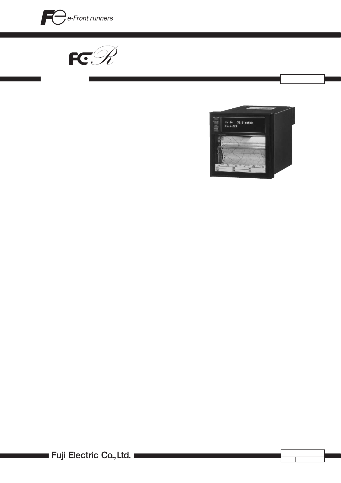
MICROJET RECORDER (100mm)
DATA SHEET
This recorder can record a maximum of 6 channels of
DC voltage, mA, thermocouples and resistance bulbs.
The adoption of an ink jet system makes it possible to
record measured data in analog trace mode or to print in
digital mode at a high speed. This 100mm-wide recorder
performs recording clearly in 6 different colors.
FEATURES
1. Compact size
Compact and lightweight design, 199mm in depth and
about 2.1kg in mass{weight}.
2. High quality recording
• In k jet syste m is us ed for reco rding an d prin t ing
meas-ured data in 6 different colors at a high speed.
Operating noise is minimized.
• Six continuous traces without pen offset are possible
with this compact size of recorder; a unique recording system is used for the first time in the industry.
• Scale of each channel is printed on chart paper, eliminating the need for scales.
3. Easy setting of input signals
DC volt age input (5mV span, 50V max.), 12 kinds of
thermocouples (Type B, R, S, K, E, J, T, N, W, L, U, PN)
and resistance bulbs (Pt100) can be set for each channel.
4. Digital printing
Beside the analog recording of measured data, digital
printing is also available (periodic printing, list printing,
alarm printing, daily report printing, message printing).
• Periodic data printing: Channel No., date, time, unit,
chart speed, measured value
• List printing: Date, time, unit, recording range, scal-
ing value, alarm set value, chart speed, Tag No.
• Alarm printing: Channel No., alarm type, on/off time,
output relay No.
• Daily report and totalized data printing: Printing of
maxim um, mi nim um, aver age and tot al of data
measured during maximum 24 hours
• Message printing : 10 messages, 16-character user-
entered messages
5. Interactive key operation
Fluorescent indicator is used to clearly indicate alpha-
numeric characters and symbols.
Input mode, recording range, alarm value, chart speed,
etc., can be set according to the comments indicated
by the display and operating keys. No bothersome operation is required.
PHC
6. Easy handling
• A cartridge type recording device is used for easy
replacement.
• Allow to draw out the chart paper while recording.
• Sho rt age of ink is detected in early stages and an
alarm is given to the operator.
• The end of chart paper is detected and indicated on
the front panel display.
• Shortage of ink and the end of chart paper alarm output is possible.
7. Full variety of functions
• Alarm relay output/external control (record start/stop,
chart speed change, data printing, message printing).
This unit can easily be connected to the recorder by
user (option).
• Chart paper illumination lamp (option): The result of
printing can be checked even in lower light.
• Burnout function is provided as a standard.
• Various recording: Enlarged/reduced recording, autorange recording, zone recording.
• Calculation: Square root extraction, subtraction, engineering unit conversion, logarithm.
• La ngua g e: Sel ectabl e 3 la nguag es in display and
printing.
• Passcode security is configurable.
• Transmission function: RS-485 (option)
• The message print and alarm print function are operational, even when the recording mode is off.
• Al l pa r ameter s of rec o rding format, dai l y re p ort,
totalize, message and periodic dat a printing can be
printed out.
EDSX10-61j
Date
Nov. 24, 2011
Page 2

PHC
SPECIFICATIONS
Input system
Input points: 3 or 6 continuous recording
6 intermittent recording
Input signal: Thermocouple input...B, R, S, K, E, J, T,
N, W, L, U, PN
Resistance bulb input...Pt100
DC volt age input.. .50m V, 50 0mV, 5V,
50V range
DC current input...4 to 20mA DC, 10 to
50mA DC
(S hunt resis tor (optio n) nee d to be
connected to the terminal)
Max. input voltage:
• Ther moco upl e, resis t anc e bul b and
DC voltage (50mV, 500mV range)
...±10VDC or less
• DC voltage input (5V, 50V range)
...±100VDC or less
Input signal setting and change:
Setting and change of input signal be-
twee n thermocoup le, resista nce bulb
and DC voltage (50mV, 500mV, 5V, 50V
range) is possible for each channel by
the setting pin in the instrument.
Setting of recording range:
Setting is possible within the reference
range by using the keyboard.
Burnout function:When thermocouple or resistance bulb
input is disconnected, the recording is
deflected to 100%.
Reference range:
Kind Reference range Reference range
Thermo-
couple
Resistance
bulb
DC voltage -50 to +50mV Scaling is possible
Note: N : NICROSIL-NISIL (IEC584)
W : +side 5% Re,
L : +side Fe,
U : +side Cu,
PN : Platinel
Pt100 : DIN IEC751
B 400 to 1760°C 752 to 3200°F
R 0 to 1760°C 32 to 3200°F
S 0 to 1760°C 32 to 3200°F
K -200 to 1370°C -328 to 2498°F
E -200 to 800°C -328 to 1472°F
J -200 to 1100°C -328 to 2012°F
T -200 to 400°C -328 to 752°F
N 0 to 1300°C 32 to 2372°F
W 0 to 1760°C 32 to 3200°F
L -200 to 900°C -328 to 1652°F
U -200 to 400°C -328 to 752°F
PN 0 to 1300°C 32 to 2372°F
Pt100 -200 to 600°C -328 to 1112°F
-500 to +500mV
-5 to +5V
-50 to +50V
-
U.S.A.)
side 2 6% Re.W (Hos kin s Mfg. Co.,
-
side Cu.Ni alloy (DIN43710)
-
side Cu.Ni alloy (DIN43710)
within the range of
-32767 to +32767
(decimal point may be
put as necessary)
Recording system
Writing system: Ink jet system, 6 colors
Chart width: 100mm
Recording color: No. 1 channel (orange), No. 2 channel
(green), No. 3 channel (purple), No. 4
cha nne l (re d), No. 5 channel (b lack) ,
No. 6 channel (blue)
Recording color can be assig ned for
2
each channel.
Ω
Chart length: Z fold 15.08m
Chart speeds: Continuous recording type
5 to 400 mm/h, continuous recording
401 to 1500 mm/h, inte rmittent re-
cording
Intermittent recording type
5 to 1500 mm/h
Each can be set in 1 mm/h steps.
Recording cycle: Intermitter recording...30 sec/all points
Cont i n uous rec o rding .. .Dep e n ds on
chart speed.
<Calculation formula>
Recording
cycle [sec] Chart speed [mm/h]
=
400
(not faster than 2 seconds.)
Measuring cycle: Up to 3 inputs...160ms
6 inputs...320ms
Service life of ink: (Depends on operating conditions)
About 6 months for 6 points of linear
recording at 20 mm/h of chart speed
Chart handling:
Indicating system
Tear off without disturbance of recording.
Indication: Fluorescent indication (blue-green),
20 characters x 2 lines
Characters indicated:
5 x 7 dots, 4.16mm high, 2.25mm wide
Contents of indication:
(1) Measured value:
Temperature...1 digit below decimal
point;
Vo l t a g e ...6 digits (in c l uding sign
and decimal point)
Measured value of No.1 channel to
No.6 ca n be indicate d simult ane-
ously.
(2) Channel No.: 1 digit (1 to 6)
(3) Engineering unit: Max. 7 digits (°C,
°F, %, Pa, bar, ppm, m
3
/h, etc.)
(4) Tag No....8 characters
(5)
Time: Year, month, day, hour, minute
(6) Status indication: Record ON, chart
end, battery alarm, alarm, ink shortage alarm, burnout, carriage failure
Configuration: Th e s e can be set ac c o r d i n g to th e
comments indicated by operating keys
as follows,
Passcode
Main chart speed
Sub chart speed
Alarm setting
Record mode (trend/logging)
Recording range
Input signal
List print request
Tag No.
Daily report setting
Totalize function
Communication parameter
Date and time setting
Ink monitor clear
Illumination on/off
Message definition
Measured value shift
Page 3

Printing system
Writing system: Ink jet system, 6 colors
Periodic data printing:
Measured value, unit, date, time, time
line, chart speed, channel No.
List printing: (1) Measu r e d va l ue list (date, tim e ,
channel No., measured value, unit)
(2)
Paramet er list (d ate, time, chan nel
No., recording range, scali ng, unit,
alarm set value, chart speed, Tag No.)
(3) Te s t pa tter n (all ch a r ac te rs an d
color patterns)
Message printing: 10 mes s ag e s, 16 - ch ar a ct e r us er-
entered messages
Alarm printing: Cha nnel No., alarm type ( H, L, RH,
RL), output relay No., on/off time
Burnout printing: Burnout channel No. and time
Other: Ink sho r t age mes s a g e, au toma t i c
range selection mark, recording start
mark, chart speed change mark
Note: Pri nting i s not available fo r more than 401 mm/h ( conti nu ous
recording), or more than 51 mm/h (intermittent recording).
Performance and characteristics
Accuracy and resolution:
Performance un der reference condi-
ti o n (23± 2 ° C, 65± 1 0%RH , po w er
voltage and frequency variation ±1%,
wa rm-u p time 30 mi nute s or mor e,
vertical mounting, free from the effect
of external noise)
Input
T h e r -
B
mo-
R 0.1°C
couple
S 0.1°C
K 0.1°C
E 0.1°C
J 0.1°C
T 0.1°C
N 0.1°C
W 0.1°C
L 0.1°C
U 0.1°C
PN 0.1°C
R e s i s tance
Pt100
bulb
DC
-50 to +50mV ±(0.15%
voltage
-500 to +50 0mV 100µV
-5 to +5V 1mV
-50 to +50V 10mV
Note: Indication accuracy is in % of reference range.
Indication accuracy of B type TC is ±(0.36% + 1digit) between
400°C to 600°C.
Indication accuracy of all type TC is ±(0.36% + 1digit) between
-200°C to -100°C.
Input resistance: Thermocouple:>10M
50mV range: >10M
500mV range: >100k
5V and 50V range: >1M
Chart speed accuracy:
±0.1% (expansion and contraction of
Clock accuracy: ±50ppm or less (monthly error; about
Imsulation resistance:
100MΩ or more (between each termi-
Indication (digital) Recording
Accuracy
±(0.15%
+1 digit)
(without
reference
junction
compen sation
error)
±(0.15%
+1 digit)
+1 digit)
Resolution
0.1°C
0.1°C
10µV
Accuracy
Indication
accuracy,
±0.25%
of recording span
Ω
Ω
Ω
Ω
paper is not included)
2 minutes)
nal and earth, at 500V DC)
Resolution
0.1mm
minimum
Withstand voltage:
Input terminal - input terminal...500V
AC, 1 minute
Powe r su p p l y te r mina l - gr o u n d...
2000V AC, 1 minute
Input terminal - ground...50 0V AC, 1
minute
Power terminal - input terminal...500V
AC, 1 minute
Between alarm terminals...750V AC, 1
minute
( Leakag e curre nt 5mA or less, how-
ever, if the power supply is 24V DC,
Le a kage current of “Power supply
terminal - ground” is 10mA or less)
Reference junction compensation accuracy:
K, E, J, T, N, L, U, PN ..... ....... ±0.5°C
(In case of minus input measurement:
±1.2°C)
R, S, B, W ............................. ±1°C
(In case of minus input measurement:
±2.4°C)
Common mode noise rejection:
120dB at 50, 60Hz ±0.1Hz
Series mode noise rejection:
30dB at 50, 60Hz ±0.1Hz
Physical data
Mounting: Panel (may be inclined up to 30 ° back-
wards from the vertical.)
=90~60°
α
Two more recorders can be mounted
side by side.
Material: Case...Steel plate
Front door frame...Polycarbonate with
glass wool
Mass{weight}: Approx. 2.1 kg (without option)
Approx. 2.2 kg (with option)
Case size: Bezel 144x144mm
Depth 199mm
Cutout 137x137mm
Finish color: Case...Black, Front door frame...Black
External terminals:Screw terminal (M4 screw)
Power requirement
1) Supply voltage 100 to 240V AC products (9digit of
code symbol = “D”)
• Power supply voltage:
100V (-15%) to 240V (+10%) AC (Free
power supply)
• Supply frequency:
50/60Hz both employable
• Power consumption:
100V AC with all options approximate-
ly 26VA
2) Supp l y vo ltage 24V DC pro d u cts (9di g i t of code
symbol = “L”)
• Power supply voltage:
24V (±10%) DC
• Power consumption:
26.4V DC with all options 26VA or less
3
Page 4

PHC
Operating environment
(for devices to operate continuously)
Usage environment
Temperature limits:
0 to 50°C
Humidity limits: 20 to 80%RH, non condensing is re-
(temperature x humidity<3200)
Vibration: 10 to 60Hz, 0.2m/s
Mounting position:
Fro n t incl inati on 0°, re a r incl inati on
Signal source resistance:
Thermocouple input...1kΩ or less
Voltage input...Less than 0.1% of in-
Resistance bulb input...Less than 10 Ω
Warm-up time: 30 min or more
Shock: No external shock
Environmental protection:
IEC IP50(Front) / 20(Terminal)
[Not covered by UL approval]
Installation category:
Pollution degree: 2
Operating altitude:
2000m max.
: Indoor
quired
30°, left/right inclination 0°
put resistance
per line (Resistance of each wire of
3-wire system should be balanced
with others.)
Ⅱ
2
{0.02G} or less
Operating environment influence
Effect of power supply fluctuation :
(1) Supply voltage 100 to 240V AC products (9th digit
of code symbol = “D”)
Voltage variation: 85 to 264V AC
(frequeucy: 50/60Hz) 100VAC base
Ch ange in ind icat ion… ±(0.1 %+1
digit) max.
Ch a n g e in rec o r d ing… ±0.2% of
recording span, max.
Frequency variation: 47 to 63Hz
(power voltage: 100V AC) 50Hz base
Ch ange in ind icat ion… ±(0.1 %+1
digit) max.
Ch a n g e in rec o r d ing… ±0.2% of
recording span, max.
(2) Supply voltage 24V DC products (9th digit of code
symbol = “L”)
With 21.6 to 26.4V DC fluctuation,
24V DC base
Change in indication....±(0.1% + 1
digit) max.
Change in recording....±0.2% of re-
cording span, max.
Input signal source resistance or wiring resistance influence:
Thermocouple... 10µV per 100
Vo l ta g e in p u t. . .Va ri a t io n of 0. 1 %
change of resistance
Ch ange in indic atio n... ±( 0.1% +1
digit) max.
Change in recording... ±0.2% of re-
cording span, max.
Re i s t a n c e bulb . . . Var i a t i o n of resis-
tance with changes in 10Ω per wire
Ch ange in indic atio n... ±( 0.1% +1
digit) max.
Ω
Ch a n g e in rec o r d ing ... ±0.2% of
recording span, max.
(3 wires should be balanced.)
Temperature influence:
Change in indication... ±(0.3%+1digit)
/10°C, max.
Ch ang e in re cord ing.. . ±0. 5%/10°C,
max.
Mounting position influence:
Inclination within 30°
Ch ange in indic atio n... ±( 0.1% + 1
digit) max.
Change in recording... ±0.2% of re-
cording span, max.
Vibration influence:
Li n ear vib r ation wi t h 10 t o 60 H z of
freque ncy and 0.2m/s
celeration is applied to each of 3 directions for 2 hours.
Ch a n g e in indica t i o n . . . ±(0.1%+1
digit) max.
Change in recording... ±0.2% of re-
cording span, max.
Effect of external noise:
Normal mode noise (50,60Hz±0.1Hz)
... 30dB or more
Common mode noise (50,60Hz±0.1Hz)
… 120dB or more
Chart paper influence:
Standard temperature/humidity: 20°C,
65%RH
Expansion at 85%RH... 0.4% max.
Contraction at 35%RH... 0.5% max.
Alarm
Setting method: Setting from keyboard
Number of alarm levels:
Max. 4 levels for each channel
Alarm types: High(H), Low(L), High-rate of
Alarm action indication:
Kind of alarm and output relay No. are
Printing: Channel No., kind of alarm, output re-
Output: See optional specifications.
Hysteresis: Approx. 0.5% of recording span
Alarm timing:
Action; additional 1 second (worst case)
Alarm latch:
Others: Shortage of ink and the end of chart
Transportation/storage condition
(Detach a recording head from the main unit before transportation)
Temperature limits:
Humidity limits:
Vibration: 10 to 60Hz, 2.45m/s2{0.25G}
Shock: 294m/s
change(RH), Low-rate of change(RL)
indic ated for ea ch chan nel at occur-
rence of alarm.
lay No. and on/off time are printed on
chart paper.
Recognition; 1 second (worst case)
Hold the alarm display and alarm output.
paper alarm output is possible.
-
10 to +60°C
5 to 90%RH, non condensing is required
2
{30G} or less
2
{0.02G } of ac-
4
Page 5

Optional specifications
1. Chart illumination:
LED
2. Alarm output/3-point external control:
This uni t can be mou n ted fro m the
rear side of the recorder.
(1) Alarm output (DO):
6 points of relay contact N.O. (1a) or
N.C. (1b) output for individual channel
operation or common operation
Contact capacity:
N.O. contact 240V AC/3A
30V DC/3A
(resistive load)
N.C. contact 125V AC/0.4A
30V DC/2A
(resistive load)
Only following specifications obtain
UL approval.
1a con t a c t 30 V AC
/30V DC 3A
(resistive load)
(2) External control (DI):
The following control is possible with
external contact signal.
• Recording start/stop;
Recording start/stop is effected by
contact signal. Recording is started
when contact is closed and stopped
when contact is open.
• Chart speed change;
Selection between normal and re-
mo te chart spe eds is effec ted by
contact signal. Remote chart speed
is selected when contact is closed
and normal when contact is open.
• Measured value printing;
• Message printing
Note:
Co n t act cap a cit y : 12V DC, 0.0 5A,
3. Transmission function:
R S - 48 5 int e rfa c e fo r tr a ns m i tt in g
Transmission method Half-duplex bit serial
Synchronizing method St art-stop synchronizing
Code Binar y Data length, 8 bits
Transmission speed 2400, 4800, 960 0, 19200 bps
Number of units connected Max. 31 units
Transmission dist ance Max. 1 km
Remarks: When c on ne ct ing through RS-232C, b e sure to use a
232 to 485 converter.
The following shows a recommended converter.
Maker: System Sakom Co., Ltd., Japan
Tel: +81-3-3797-0211
Type: KS-485
Meas u r e d val u e li s t pr i n t i n g (d a t e ,
ti m e , channel No., meas u r e d va l u e,
unit) is effected by contact signal. Printing is started when contact is closed.
For external control, use a dr y contact.
N.O. (1a) cont act
meas-ured value and receiving the
condition of setting.
Parity: odd/even/none
Stop bit: 1 or 2
FUNCTIONS
Function Description
Range setting Recording range can be set for each channel.
Input setting Any input can be set for each channel.
Skip function
Measured
value list
Parameter list
Test pattern
List printing function
Periodic dat a
printing function
Message
printing
Alarm printing
function
Unit indication Engineering units such as °C, °F, %, mV, mA,
Scaling function Scaling with DC voltage input is possible. (Set-
Subtract function Differe nce between any cha nne ls is re corded
Logarithm Measurd value can be displyed and printed by
Auto-range
recording
Zone recording Recording area is divided into a maximum of 3
Enlarged/reduced
recording
Square-root extraction function
Daily report
function
Tot alize function Int eg rated value of every h our for maximu m
Measured value
shift
Memor y backup S et data and clock func tion are protected by
Input filter Re s p ons e is de l ay e d ac c o r ding to su d d en
Burnout function When thermocouple or resistance bulb input is
Passcode 4 digits passcode security is available.
Language Engl is h, G er ma n, o r French is select ab le fo r
Used to skip recording, indication and alarm at
any measuring point.
Date, time, and measured value unit can be
printed.
Date, time, recording range, scaling, unit, kind
of input, alarm set value, chart speed, and Tag
No. can be printed.
All characters and color patterns can be printed.
Time, date, chart speed, measured value and
unit ca n be printed at fixed inter vals. Printing
can be enabled/disabled from keyboard.
Ma xim u m 10 m es s age s, 16-cha r act er use rentered messages can be printed.
Time, channel N o., kind of alarm, and output
relay No. can be printed when alarm is on or
off.
Pa , l, et c . , ar e in dic a t ed (s ettin g fro m key
board).
ting of decimal point is also possible within the
range of -32767 to +32767).
(channel is set from keyboard).
n
power.
10
Recordi ng range is automa tic ally changed fo r
reco rding in th e event of overr ange or und errange (setting with keyboard). This function is
not available for combination of zone recording
and enlarged/reduced recording.
zones for recording.
This functio n is not availab le for combin ati on
of automatic range selection and enlarged/reduced recording.
A part of recording area of each channel is expanded or contracted for recording.
This function is not available for combination of
automatic range selection and zone recording .
Square -root extra ction of DC voltage input is
possible.
Measured valu e of ever y hour for m ax im um
on e day (24 dat a ) in each chan n el i s sto red
for printing . Maximum, minimum and average
values are also printed at the same time. ONOFF operat io n, ON-O FF of each chann el and
operation st art time/stop time can be set from
keyboard.
one day (24 data) in each channel is stored for
print ing (integration in 1 sec steps). Poss ible
to pri nt tot al v al ue only. Tot al valu e is a lso
prin ted at t he same time. ON-OFF operati on,
ON- OF F of each chann el and oper at io n star t
time/stop time can be set from keyboard.
Shift the zero point and inclination of the measured value so that the measured value can be
adjusted according to other instruments.
bui lt-in l ithiu m batter y (expect ed batte ry life,
about 10 years under normal temperature).
changes in input of each channel (1st order lag
fil ter). Ti me cons ta nt setti ng rang e: 0 to 9 00
sec (setting from keyboard).
disconnected, it is deflected 100%. Also, it is
indicated and printed at the same time.
display and printing.
5
Page 6

PHC
Alarm latch
function
Parameter
copy
The alarm display and alar m output are held
eve n after the caus e of a lar mi ng was gon e.
ON-OFF operat ion can be set from keyboard.
Canc el la tion of the hel d alar m can be m ade
from external control (DI).
Set parameters on any channel can be copied
to any other channels.
CODE SYMBOLS
1 2 3 4 5 6 7 8 - 9 1011 1213
P H C 300 - V
3
3
6
6
7
6
D
L
A
B
0
1
2
Y
R
Description
Recording points
3 continuous recording
6 continuous recording
6 intermittent recording
Power Supply
100 to 240V AC 50/60Hz Note 1)
24V DC
Chart paper illumination
Without
With
Alarm output/external control
Without
6-point alarm output (N.O.)/
3-point external control Note 2)
6-point alarm output (N.C.)/
3-point external control Note 1)
Transmission function
Without
With RS-485 Note 1)
SCOPE OF DELIVERY
Recorder, panel mounting bracket, accessories (ink cartridge (1), chart paper (1), ink absorption cloth (1)).
Instruction manual (1).
Note: Ink cartridge is not mounted on the recorder at the time of de-
livery.
Spare parts
Item Part No. Unit of quantity for sale
Ink cartridge PHZH1002 1 pc
Ch a r t pa per (0 to 50 ,
50 uniform division)
Other (optional items)
Item Type Specification
Shunt resistor PHZT1101 For 10Ω ±
Alarm output/
external control unit
The product conforms to the requirements of the
Electromagnetic compatibility Directive 89/336/EEC as
detailed within the technical construction file number
TN510406. The applicables standards used to demonstrate
compliance are:-
PEX00DL1-500 0B 1 box (6 charts)
0.1%
PHZK1601
PHZK1611
With 6-point alarm output(N.O.)/
3-point external control
With 6-point alarm output(N.C.)/
3-point external control
Note 1) This is not conformed to UL61010-1:2001approval.
Note 2) This is conformed toUL approval with conditions attached.
Please refer to "Optional specifications" on page 5.
Remarks: Input signal
Setting prior to delivery is as follows.
• Thermocouple K: 0 to 1200°C
Note: Conta ct Fuji Electric for additional fea tures not listed such as
Flow integration record and Calculation of input signals.
EN 50081-1 :-1992 Conducted and Radiated emissions
EN 50082-1 :-1992 Radiated immunity, ESD and FBT
PHC
6
Page 7

OUTLINE DIAGRAMS
(Unit:mm)
2 t 30
t
Alarm/external
control unit
(option)
Panel coutout
When mounting one unit
0
+1.5
137
Power terminal
136.4
+1.5
137
0
Input termianl
Transmission
termianl
(option)
174.4
136.4
+1.5
137
Mounting bracket
15841
199 26
When mounting multiple unit
[144 x n–6]
0
+2
0
Panel
144
144
n : Number of units
to be mounted
CONNECTION DIAGRAMS
Input terminal
Resistance
bulb
13
23
33
43
53
63
SHLD
– +
12
22
32
42
52
62
TRX2
–
– +
11 Input 1
21
31
41
51
61
TRX1
+
Thermocouple
Voltage
¨
Input 2
¨
Input 3
¨
Input 4
¨
Input 5
¨
Input 6
¨
Transmission
¨
(option)
Note: When panel mounting, two bracket are necessary
either on the top and bottom of the recorder.
Alarm/external
control unit
(option)
11
12
13
14
15
16
17
18
19 29
DI 1 Record start or message print 1
DI 2 Chart speed change or message point 2
DI 3 Measured value printing or alarm latch cancel or message print 3
21
22
23
24
25
26
27
28
DI 1
DI 2
DI 3
Alarm 1
Alarm 2
Alarm 3
Alarm 4
Alarm 5
Alarm 6
Power terminal
AC
AC
G
+
-
G
Power source
100 to 240V AC
50/60Hz
Power source
24V DC
Note: Alarm relay contact is selectable N.O. or N.C. by Code Symbols.
7
Page 8

PHC
Caution on Safety
*Before using this product, be sure to read its instruction manual in advance.
International Sales Div
Sales Group
Gate City Ohsaki, East Tower, 11-2, Osaki 1-chome,
Shinagawa-ku, Tokyo 141-0032, Japan
http://www.fujielectric.com
Phone: 81-3-5435-7280, 7281 Fax: 81-3-5435-7425
http://www.fujielectric.com/products/instruments/
Information in this catalog is subject to change without notice.
Prin ted i n J ap an
 Loading...