

Page 1
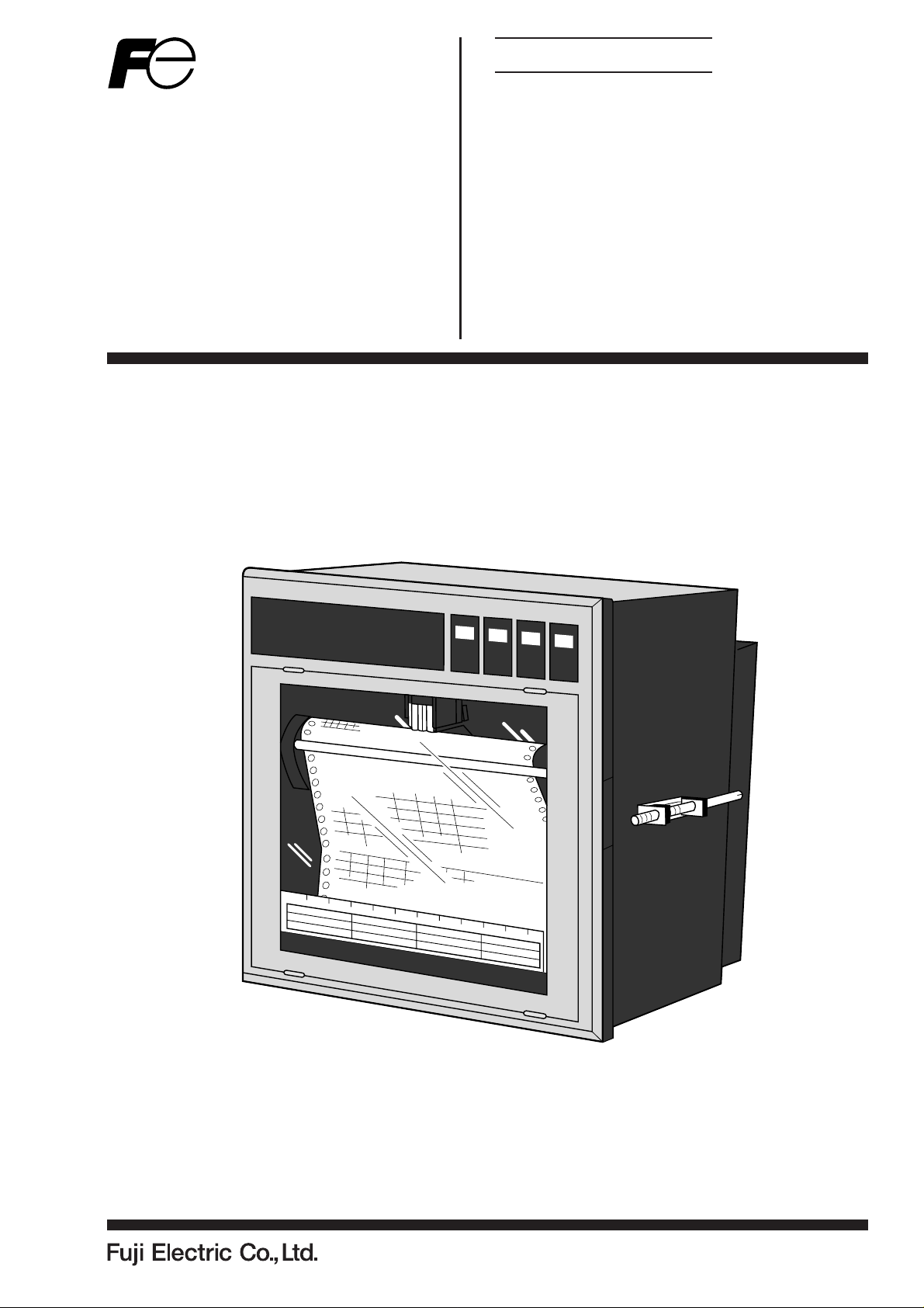
Instruction Manual
MICROJET RECORDER
TYPE: PHA
INP-TN4PHAVc-E
Page 2

PREFACE
Congratulations on your purchase of Fuji Micro-jet Recorder (Type: PHA)
• Read this instruction manual carefully to ensure correct installation, operation and preparation.
Incorrect handling may lead to accident or injury.
• Specifications of this unit is subject to change without prior notice for improvement.
• Modification of this unit without permission is strictly prohibited.
Fuji will not bear any responsibility for a trouble caused by such a modification.
• This instruction manual should be kept by the person who is actually using the unit.
• After reading the manual, be sure to keep it at a place easy to access.
• This instruction manual should be delivered to the end user without fail.
Manufacturer : Fuji Electric Co., Ltd.
Type : Shown on nameplate of Micro-jet recorder
Date of manufacture : Shown on nameplate of Micro-jet recorder
Product nationality : Japan
Request
• It is prohibited to transfer part or all of the manual
without Fuji's permission.
• Description in this manual will be changed without prior
notice.
Fuji Electric Co., Ltd. 2000
Issued in Nov., 2000
Rev. 1st edition Nov., 2002
Rev. 2nd edition Apr., 2011
Rev. 3rd edition Oct., 2011
iINP-TN4PHAV-E
Page 3
CAUTION ON SAFETY
First of all, read this "Caution on safety" before using the unit.
• The cautionary descriptions listed here contain important information about safety, so they should
always be observed.
DANGER
CAUTION
Those safety precautions are ranked to 2 levels, DANGER and CAUTION.
Wrong handling may cause a dangerous situation, in which there
is a risk of death or heavy injury.
Wrong handling may invite a dangerous situation, in which there
is a possibility of medium level trouble or slight injury or only
physical damage is predictable.
Items which must not be done are noted.
PROHIBITION
Caution on Installation
•This unit is not an explosion-proof type. Do not use it in a
DANGER
place with explosive gases to prevent explosion, fire or other
serious accident.
CAUTION
CAUTION
•For installation, select a place observing the operating conditions noted in the instruction manual.
Installation at an unsuited place may cause fall, trouble or
malfunction.
• The unit must be installed correctly as shown in the instruction manual. Incorrect installation may cause fall, trouble or
malfunction.
• During installation work, keep the inside of the unit free from
entry of cable chips or other foreign objects as it may cause
fire, trouble or malfunction.
This unit is a component device used for instrumentation. It is
mounted on a panel or in a rack.
• The unit conforms to IEC1010-1 (1990) Safety Standards, and
is designed for protection class I, overvoltage Category II and
pollution degree 2, except the alarm output terminal (overvoltage category I).
•EMC conforms to EN50081-1 (1992) and EN50082-1 (1992),
(both used for housing areas), except that the noise level of the
power terminal is rated for Class A (used for commercial and
industrial areas).
• Input signals and communication interface should be of SELV
(safety separated from hazardous voltage).
ii INP-TN4PHAV-E
Page 4
Caution of Wiring
DANGER
Caution on Maintenance
DANGER
•Wiring work must be performed as specified.
If the unit is not earthed, it would result in electric shocks or
malfunction.
• Be sure to connect power source that matches the rating.
Connection of incorrect rating of power source may lead to fire.
• Before starting wiring work, be sure to turn OFF the main power
to prevent electric shocks.
•
Wiring materials to be used must meet the rating. Use of materials
which do not withstand the rating may cause a fire accident.
• When disposing of the recording head, put it in a vinyl bag and
seal it to prevent the diffusion of ink. It should be handled as an
imcombustible object when disposing of it.
• Ink is harmful to human body. Observe the following emergency treatments.
- When ink gets in eyes, wash out for at least 5 minutes immediately with much clean water, and ask your doctor for treatment at once.
- When ink gets on skin, wash out and clean skins with soap
and water.
- When ink is breathed in, move to a clean place immediately.
If necessary, ask your doctor for treatment at once.
• Do not touch the connector at the rear of the carriage mounting
the recording head to avoid the risk of electric shocks.
Caution on Use
DANGER
• If the fault or anomaly of the device may cause serious accident or troubles to other devices, externally install appropriate protective circuit to avoid accidents.
• When fuse is blown out, check and remove the cause of it,
and replace it with new one specified in the instruction manual.
Do not use any other fuse or short it, as it may cause electric
shocks or fire.
iiiINP-TN4PHAV-E
Page 5

CONTENTS
PREFACE ...................................................................................................................................i
CAUTION ON SAFETY ............................................................................................................. ii
1. INTRODUCTION ............................................................................................................. 1-1
1.1 About the microjet recorder ................................................................................................. 1-1
1.2 Product check ....................................................................................................................... 1-1
1.3 Check on type and specification .......................................................................................... 1-2
2. NAMES AND FUNCTIONS OF PARTS........................................................................... 2-1
3. MOUNTING METHOD..................................................................................................... 3-1
3.1 Mounting location ................................................................................................................ 3-1
3.2 External dimensions and panel cut out dimensions ............................................................. 3-1
3.3 Method of mounting onto panel........................................................................................... 3-2
4. WIRING ........................................................................................................................... 4-1
4.1 Before doing the wiring ....................................................................................................... 4-1
4.2 Connection of wires to terminals ......................................................................................... 4-1
5. SET-UP ............................................................................................................................ 5-1
5.1 Loading chart paper ............................................................................................................. 5-1
5.2 Recording head installation (replacement) .......................................................................... 5-4
5.3 Changing the type of input signals....................................................................................... 5-9
6. OPERA TION AND ACTIONS .......................................................................................... 6-1
6.1 Before running the equipment: ............................................................................................ 6-1
6.2 Power switch-on and states .................................................................................................. 6-2
6.3 Test pattern print-out ............................................................................................................ 6-3
6.4 Actions during operation...................................................................................................... 6-3
6.5 Displays and print-outs on detection (cancellation) of alarms............................................. 6-5
6.6 Displays and print-outs on occurrence of burnt-out............................................................. 6-5
6.7 Over-range, under-range display and abnormal input display .............................................6-6
6.8 Display and record when chart paper runs out (“Chart End” display) ................................ 6-6
6.9 Display and record when the recording head ink is low (“Ink Out” display) ...................... 6-6
6.10 Display when data backup batteries need to be replaced (“Battery End” display).............. 6-7
6.11 Display of fault in recording head carriage (“Carriage Alarm” display) ............................. 6-7
6.12 Order of priority of state displays ........................................................................................ 6-7
7. SETTING AND CHECKING PARAMETERS ................................................................... 7-1
7.1 Setting and checking ............................................................................................................ 7-1
7.2 Outline of procedure for setting parameters ........................................................................ 7-3
7.3 Pass code setting .................................................................................................................. 7-4
7.4 Setting the chart speed ......................................................................................................... 7-5
7.5 Setting alarms....................................................................................................................... 7-7
Chapter 3, 4 and chapter 8 should be observed for installation and mainte-
CAUTION
nance of the unit. So, it must be performed by qualified engineers.
iv INP-TN4PHAV-E
Page 6

7.6 Setting the recording mode .................................................................................................. 7-8
7.7 Setting record ranges.......................................................................................................... 7-12
7.8 Setting kind of input, skip, unit, filter, scaling, subtraction ............................................... 7-13
7.9 Setting Tag Nos. ................................................................................................................. 7-19
7.10 Message print specification................................................................................................ 7-20
7.11 List print-out specification ................................................................................................. 7-23
7.12 Daily report specification ................................................................................................... 7-24
7.13 Specifying totalize function ............................................................................................... 7-26
7.14 Transmission specification (option) ................................................................................... 7-27
7.15 Setting the time .................................................................................................................. 7-29
7.16 Clearing the ink monitor .................................................................................................... 7-30
7.17 Turning the chart illumination lamp on/off (option).......................................................... 7-31
8. MAINTENANCE - INSPECTION ..................................................................................... 8-1
9. APPLICATION FUNCTIONS ........................................................................................... 9-1
9.1 Adjustment of backlash........................................................................................................ 9-1
9.2 Zero/span adjustment for analog trend recording position .................................................. 9-2
9.3 Setting of alarm latch and integrated value print-out ........................................................... 9-3
9.4 Setting of PV shift................................................................................................................ 9-4
9.5 User definable unit ............................................................................................................... 9-5
9.6 Setting of record error external output ................................................................................. 9-6
9.7 Calibration of measured value ............................................................................................. 9-6
9.8 Change of record color......................................................................................................... 9-8
9.9 Language selection............................................................................................................... 9-8
10. TROUBLESHOOTING ................................................................................................... 10-1
11. EXAMPLES OF RECORDS AND PRINT-OUTS ........................................................... 11-1
11.1 Periodic print-outs, scale print-outs ................................................................................... 11-1
11.2 Digital print-out (instantaneous values) ............................................................................. 11-2
11.3 Parameter list print-out....................................................................................................... 11-3
11.4 Test pattern ......................................................................................................................... 11-3
11.5 Scale print-outs .................................................................................................................. 11-3
11.6 Daily report print-out ......................................................................................................... 11-4
11.7 Data sum list print-out ....................................................................................................... 11-5
11.8 Message print (manual print) ............................................................................................. 11-5
11.9 Logging .............................................................................................................................. 11-6
11.10 Alarm print-outs ................................................................................................................. 11-6
11.11 Burn-out print-out .............................................................................................................. 11-6
11.12 Ink dry-up warning print-out.............................................................................................. 11-6
11.13 Record start mark ............................................................................................................... 11-7
11.14 Chart speed change mark ................................................................................................... 11-7
11.15 Auto-range change mark .................................................................................................... 11-7
12. SPECIFICATION............................................................................................................ 12-1
vINP-TN4PHAV-E
Page 7
1. INTRODUCTION
Before using the Micro-jet recorder, read this manual carefully as it describes its installation, operation,
maintenance, etc.
1.1 About the microjet recorder
(1) This recorder is a multirange input recorder 180mm wide which can record up to a maximum of 12
points using thermocouler/resistance bulb and DC voltage input signals.
(2) It effects high-speed recording and gives clear analog trend records and digital print-outs in 6
colors.
(3) The analog trend records can be given as continuous record type or as intermittent (dot) records.
(See Section 1.3, Format specification.)
(4) As well as providing records of measurement values, the standard unit has a wide range of print-
out functions comprising, e.g., the print-out of dates, chart speed, measurement ranges, Tag Nos.,
daily reports and integrated totals.
(5) Operation of the equipment is simple thanks to an easy-view display section which permits key-in
of various items of set data.
1.2 Product check
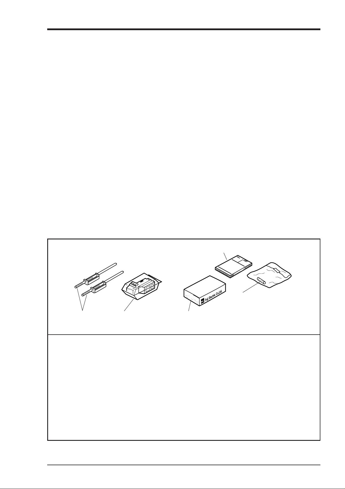
Check on accessories.
The unit comes with the accessories shown in Fig. 1-1. Please check that they are all there.
(4) Instruction manual
Instruction Manual
F
u
ji
E
le
c
t
r
ic
C
o
.,
L
t
d
.
(5) Fuse
(1) Panel fitting
(2) Recording head
(with cloth for blotting ink)
(1) Panel fitting ................................................................................................. 2
(2) Recording head (with cloth for blotting ink) ...............................................1
(3) Recording paper ..........................................................................................1 pack
(The format of standard recording paper is PEX00BL1-1000B.)
(4) Instruction manual .......................................................................................1
(5) Fuse (250V/1A AC) .................................................................................... 1
(6) Fuse (250V/3A AC) .................................................................................... 1
Note:Item 5 is appended on the back side of the main unit.
E at code symbol 9 digits(Power supply voltage; 100V to 240V AC)
Item 6 is appended on the back side of the main unit.
L at code symbol 9 digits(Power supply voltage; 24V DC)
(3) Recording paper
Fig. 1-1 Accessories
1 - 1INP-TN4PHAV-E
Page 8
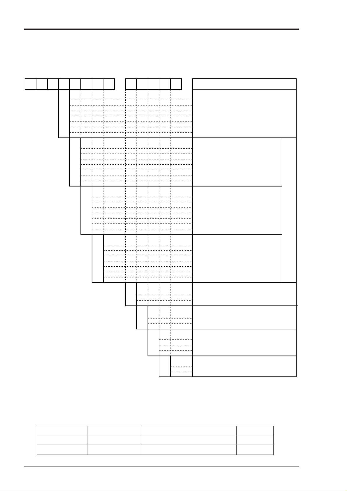
1.3 Check on type and specification
The data plates note the type name, etc. Please check to see that you have got a unit with the specification
you ordered. (There are data plates on the top surface of the case and in the main unit.)
12345678 9101112 13 places
P H A
–
4
1
2
3
6
7
8
9
0
1
2
3
6
8
Z
0
1
2
3
6
8
Z
V
/
Y
Number of recording points
1 continuous record
2 continuous record
3 continuous record
6 continuous record
6 dot records
12 dot records
12 continuouous record
Number of input signal points
None
1 point
2 points
3 points
6 points
12 points
Other specification
Number of input signal poiints
None
1 point
2 points
3 points
6 points
12 points
Other specification
Description
(thermocouples)
(resistance bulbs)
0
1
2
3
6
8
Z
E
• Ex-works values of input signals
L
Thermocouple: K 0 to 1200°C
Resistance bulbs: Pt 100 0 to 500°C
DC voltage: -5 to +5V DC
• Relations between input signal specifications
and recording channels
Ex.: If 3 thermocouple points, 6 resistance bulb
points and 3 DC voltage points are specified.
Channels 1 to 3 are thermocouple
Channels 4 to 9 are resistance bulbs.
Channels 10 to 12 are DC voltage.
A
B
0
1
2
Y
T
Number of input signal points
None
1 point
2 points
3 points
6 points
12 points
Other specification
Power supply
English 100 to 240V AC 50/60Hz
English 24V DC
Chart illumination*
Without
With
Alarm output/external control*
None
6-point alarm output, with 3-point external control
12-point alarm output, with 3-point external control
Communication*
None
with T-link
Asterisks * indicate options.
Note: The "Z" in places 5, 6 and 7 indicates a non-standard specification. Please check by the
positions of the input signal type setting pins indicated in Section 5.3.
Note: After purchasing the unit, the type of input signal can be changed within the number of the
record pins (See Item 5.3).
(DC voltage)
The total number of points must be equal to the number of
points in place 4.
• Supplementary supplies
Product name Type Specification Sales units
Recording head PHZH1002 1 per unit 1
Recording paper PEX00BL1-1000B Approximately 20m (6 packs/box) 6 packs
1 - 2 INP-TN4PHAV-E
Page 9
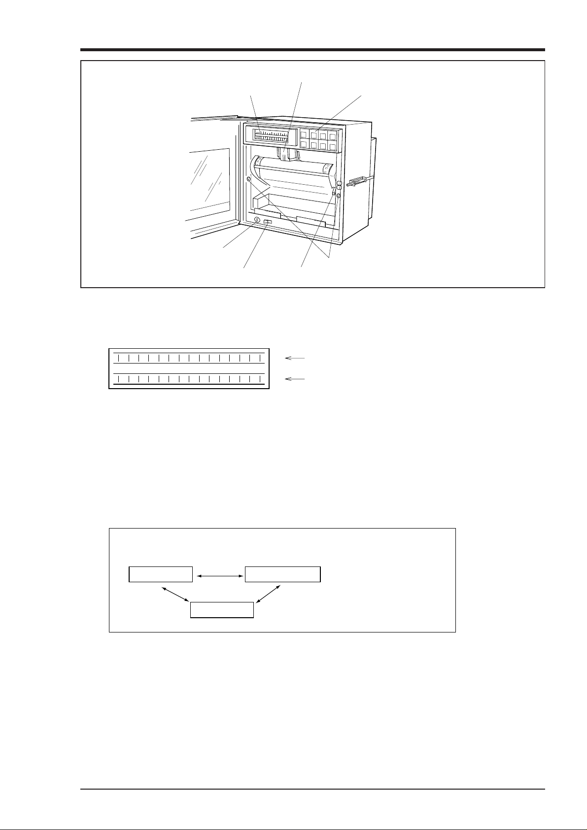
2. NAMES AND FUNCTIONS OF PARTS
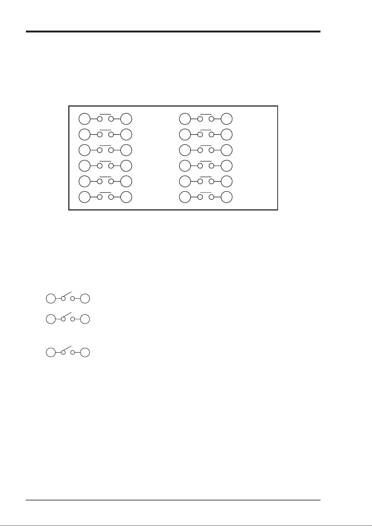
(2) Recording head
(1) Display section
(5) Fuse
(7) Key actuation section
(6) Power supply switch
(4) Lever
(3) Lock screws
(1) Display section
For displays such as measurement data, units and displays of various parameters and comments
display of units and data for each channel display of various parameters, comments
display of units and data for each channel
display of varous parameters, comments
(2) Recording head
This is a recording head which serves for analog trend recording and digital print-outs. As this is
not installed in the main unit at the time of delivery, please install it referring to Section 5.2.
(3) Lock screws
To change the type of input signals, remove the lock screws on the left and right, detach the main
unit and make changes inside the instrument (replace the input signal setting pins).
Note that changes in the type of thermocouple can be effected by front panel key operations.
* 'Changes in the type of input signals' means changes as indicated below.
Thermocouple
Resistance bulbs
DC voltage
For details, see Section 5.3.
However, change to the thermocouple model or switching between new JIS and old JIS for resistance bulb can be performed by key operation on the front face.
(4) Lever
This is a lock lever for opening and closing the recording paper holder.
(5) Fuse holder
(1) The holder contains a 250V/1A AC power supply fuse.(9th digit of code symbol : “E”)
(2) The holder contains a 250V/3A AC power supply fuse.(9th digit of code symbol : “L”)
2 - 1INP-TN4PHAV-E
Page 10
(6) Power supply switch
Used to turn on and off the power.
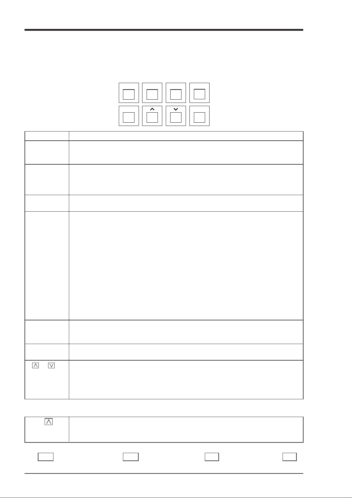
(7) Keying operation section
This is used for setting various parameters, making checks and running the equipment.
FEED LIST DISPLAY
SELECT ENTRY
RECORD
Name of key Function
RECORD Operation key for starting and stopping recording.
Recording starts when the key is pressed once and stops when the key is pressed again. This
key is ineffective during print-out of data or lists.
LIST This is used for effecting print-out of data (instantaneous values).
If you wish to stop the print-out partway through, press the key again.
The recording paper fast feed key.
This key is always valid.
FEED The speed is 3mm/sec during the first second that the key is held depressed and goes to
8mm/sec after the elapse of 1 second.
DISPLAY 1. This is used for changing the contents of displays. Successively pressing the key and
releasing it brings about the following 5 changeovers.
(1) Sequential display of the data of all channels.
However, there is no display for skip channels.
The data display is updated once every 3 seconds.
(2) Display only of the data of specific channels.
The data display is updated once every second.
(3) No 1 to 6 channels are display simultaneously, and data display is updated at 1 sec-
ond intervals.
(4) 7 - 12 channels are displayed simultaneously.
(This panel is not displayed when the number of recorded points is up to six.)
Data display is updated once every second.
(5) Display of the data and time.
2. This key is used for shifting from a set mode to the data display mode.
This key is ineffective during print-out of data or lists.
SELECT 1. Used for shifting from the data display mode to a set mode.
2. Is used for effecting sequential read-out of parameters during operation in a set mode.
This key is ineffective during print-out of data or lists.
ENTRY Is used to register set data.
This key is effective only during set mode operation.
Used to scroll numerical values up and down.
(up) (down) The values are scrolled up or down 1 count each time the relevant key is pressed. Holding a
key depressed for more than 0.5 seconds results in a fast up/down scroll at a rate of 5 counts/
second and holding it depressed for a further 2 seconds results in an ultra-fast scroll of 55
counts/second.
Special keying operations
Press
key Used for reversing the recording paper feeding direction.
while pressing (However, continuous feed is permitted up to about 25 mm.)
the FEED key.
Note) In this instruction manual some display of the keys are abbreviated as follows. RECORD key is indicated
REC , DISPLAY key is indicated DISP , SELECT key is indicated SEL , ENTER key is indicated ENT .
2 - 2 INP-TN4PHAV-E
Page 11
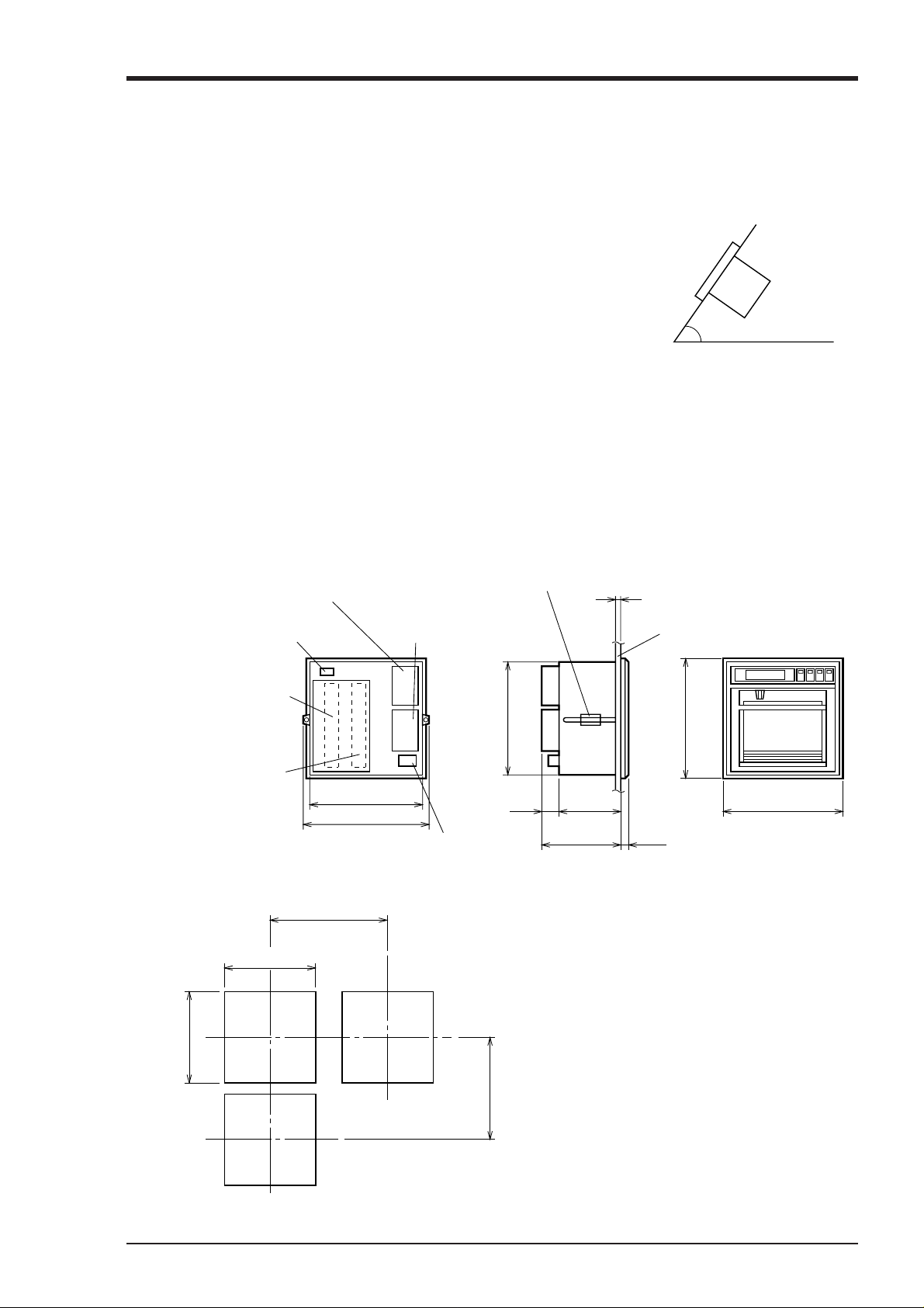
3. MOUNTING METHOD
This unit is designed to be panel mounted.
3.1 Mounting location
Select the following location for mounting the unit.
(1) A place that is not subject to vibration or impact.
(2) A place where there is no corrosive gas.
(3) A place that is subject to little temperature variation and is
close to normal temperature (23°C)
(4) A place that is not struck directly by strong radiant heat.
(5) As humidity affects the ink and recording paper, select a place
that is in the range 20 to 80% RH.
(6) Mount the unit horizontally, with no tilt to the left or right.
(The forward tilt should be 0 (but the unit may be inclined 0 to
30° rearwards.)
∠ α
∠ α = 60 to 90
3.2 External dimensions and panel cut out dimensions (unit: mm)
Mounting
attachment 2≤t≤30
Panel
280
16039
288
18199
Mass: Approximately 6kg (with all options)
Approximately 7kg (with all options)
Power consumption: Approximately 37VA
(100V AC with all options)
Less than 37VA
(26.4V DC with all options)
Alarm unit (option)
(Alarms 7 to 12)
Transmission terminal
(option)
Input terminals
(inputs 7 to 12)
Input terminals
(inputs 1 to 6)
Panel cut dimensions (unit: mm)
360MIN
+2
281
0
+2
0
281
Alarm, external
control unit
(option)
(Alarms 1 to 6)
(DI 1 to 3)
280
312
Power supply terminal
288
320MIN
3 - 1INP-TN4PHAV-E
Page 12
3.3 Method of mounting onto panel
Panel
Screw
Screw
•Tighten and fix the mounting screw attachments on the left and right.
• Use a panel that is 2mm or more thick.
3 - 2 INP-TN4PHAV-E
Page 13
4. WIRING
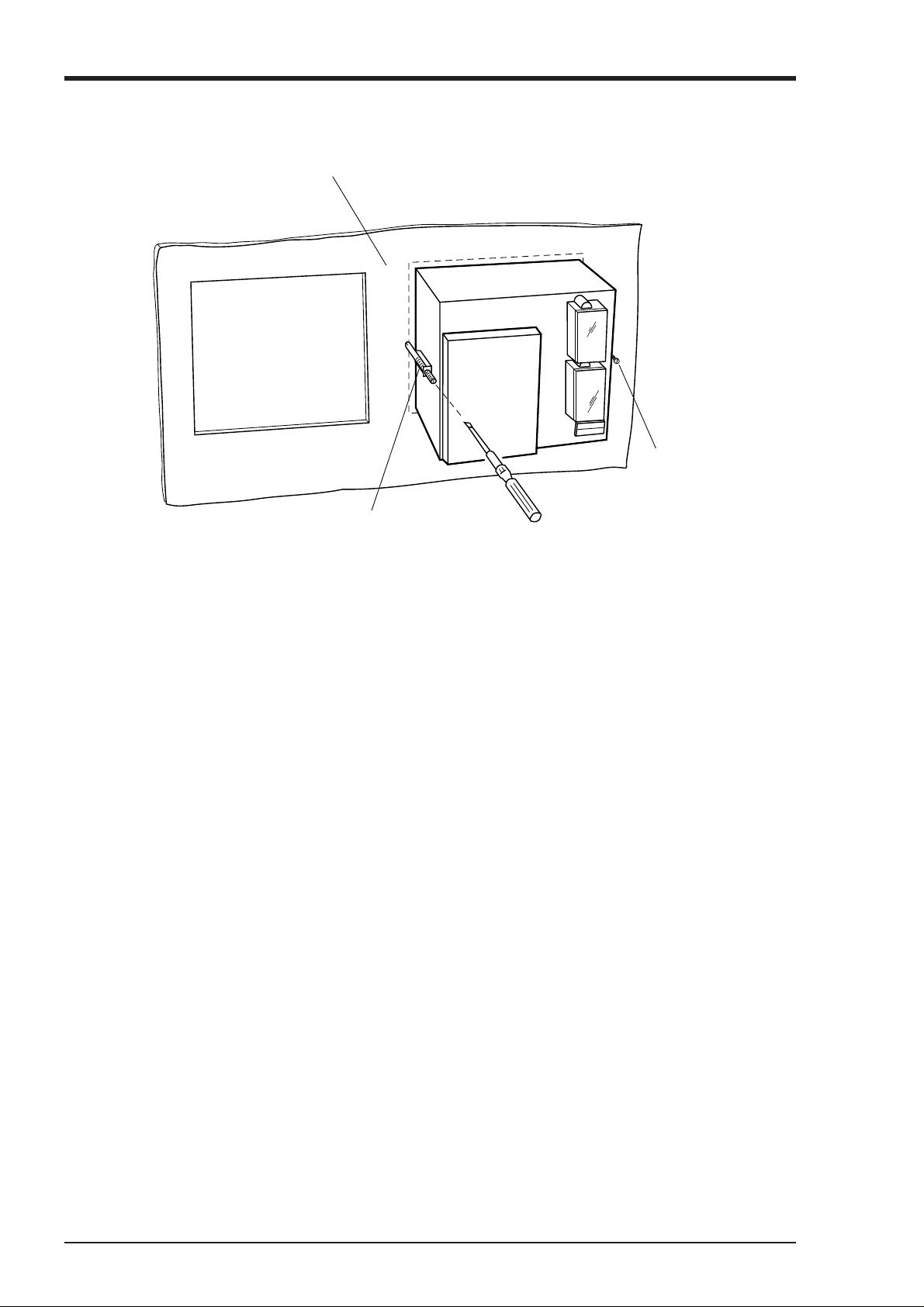
4.1 Before doing the wiring
To carry out wiring, remove the unit's rear cover (Notes).
(1) For the power cable, use a 600V vinyl-insulated cable (JIS C 3307) or a cable with equal or supe-
rior performance to this.
(2) Use compensating leads for thermocouple inputs.
(3) To avoid the effects of induction noise, keep input signal leads as far away as possible (at least
30cm) from power supply lines and lines carrying heavy current. Also, wherever possible use a
shieled cable and earth one point of the shield.
(4) For wiring the terminals, use a maximum of 2 crimp style terminals.
Notes
(1) To remove the rear cover, put a finger in a cable
through-hole in the cover, gently raise the cover
and then pull outwards.
(2) After wiring up the input terminals, always re-
place the rear cover in its original position so as
to ensure proper compensation of reference contacts for thermocouple inputs.
(3) We recommend the use of insulation-sleeve
solderless terminals (using M4 thread) for connecting wires to terminals.
4.2 Connection of wires to terminals
(1) Input terminals
➪ Connect signal leads for each channel.
(2) Alarm, external control unit (option)
➪ Connect the alarm signal outputs and ex-
ternal control signal inputs (for alarms 1
to 6, external controls 1 to 3).
(3) Alarm unit (option)
➪ Connect the alarm signal outputs (for
alarms 7 to 12).
(4) Power supply terminal
➪ 1) Connect the power cables to AC/AC terminals.
(Supply voltage 100 to 240V AC products (9th
digit of code symbol : “E”) : Free power supply ;
100 to 240V AC)
+
2) Connect power cable to terminals.
-
DC24V
(Power voltage 24V DC products (9th digit of code symbol : “L”))
3) Power source to be connected should be free from noise.
(5) Ground terminal ➪ D-class grounding with ground resistance of 100Ω or less.
(6) Transmission terminal (option) ➪ Connect the transmission signals.
(6)
(1)
(Inputs 7 to 12)
(Inputs 1 to 6)
(1)
(4)
(3)
(2)
(5)
CAUTION
Alarm unit are of overvoltage category I.
Other signal (input, communication interface) should be SELV (safety separated from
hazardous voltage).
4 - 1INP-TN4PHAV-E
Page 14
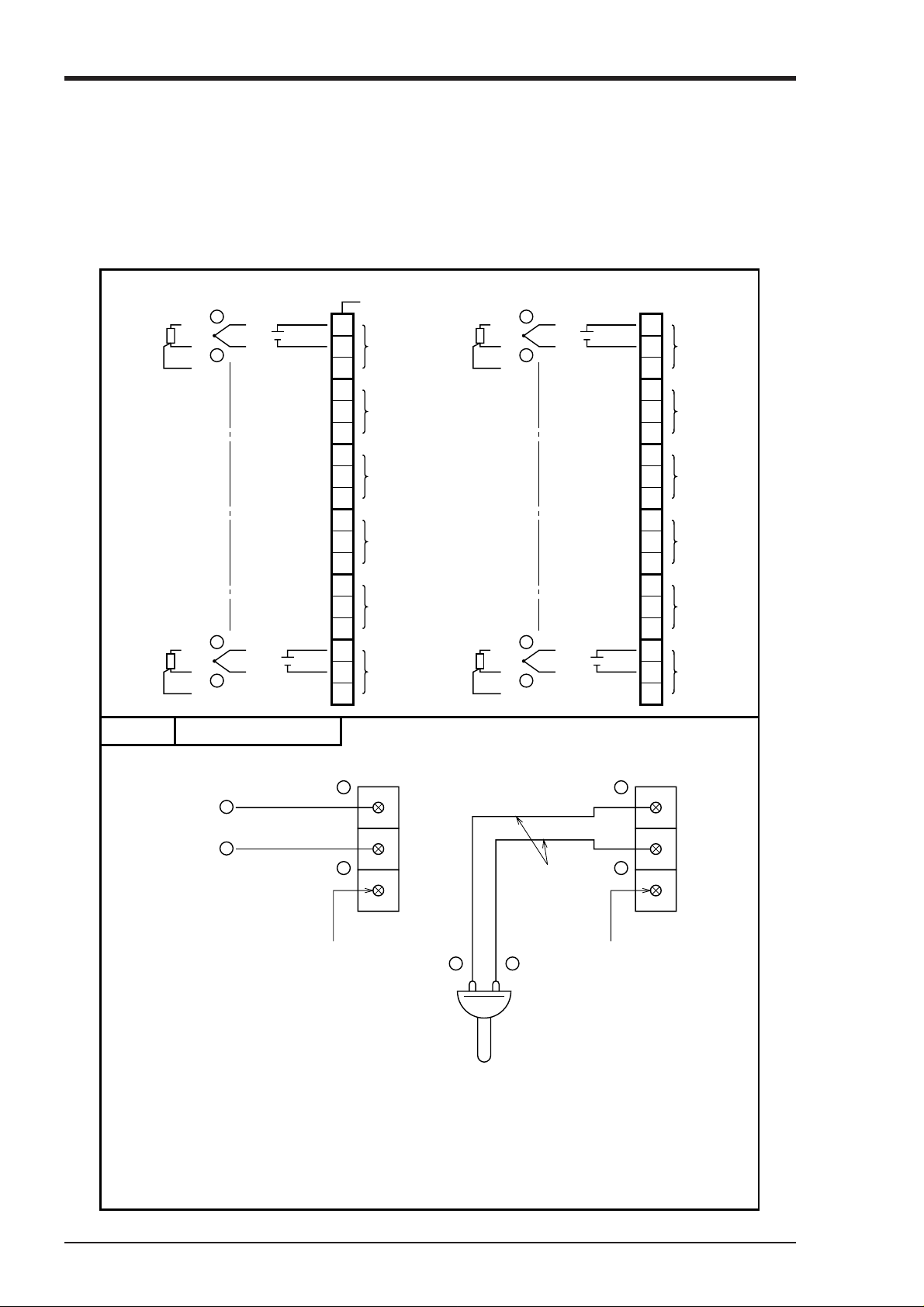
(1) Wiring of input terminals
(1) There are individual input terminal numbers for different channels.
(2) Make connection in accordance with the relation between number of input signals by type designa-
tion and channels (see section 1.3).
(3) If you decide to change the type of input signals after your purchase, be sure to remember to wire
up the requisite channel accordingly.
Resistance
bulb
A
b
A
b
Thermocouple
B
B
DC
voltage
+
–
+
–
Example Input terminal wiring
Terminal number
71
Input 7
72
(CH7)
73
81
Input 8
82
(CH8)
83
91
Input 9
92
(CH9)
93
101
Input 10
102
(CH10)
103
111
Input 11
112
(CH11)
113
121
Input 12
122
(CH12)
123
A
A
+
B
–
b
+
B
–
b
11
12
13
21
22
23
31
32
33
41
42
43
51
52
53
61
62
63
Input 1
(CH1)
Input 2
(CH2)
Input 3
(CH3)
Input 4
(CH4)
Input 5
(CH5)
Input 6
(CH6)
DC voltage input
DC voltage input
+
+
–
–
Blank Blank
11
12
13
Compensating
leads
+
–
Thermocouple input
+
21
22
–
23
Thermocouple
Note: Avoid using thermocpoule inputs with
wiring parallel to other instruments.
4 - 2 INP-TN4PHAV-E
Page 15
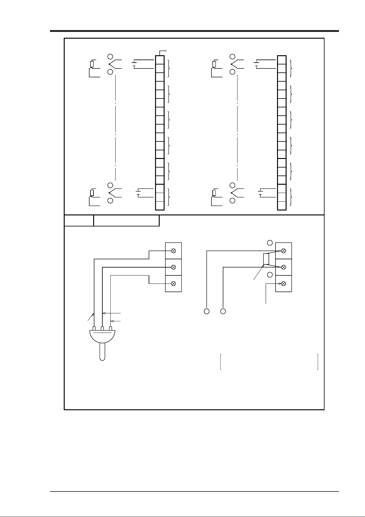
Resistance
bulb
A
b
A
b
Thermocouple
B
B
DC
voltage
+
–
+
–
Example Input terminal wiring
Terminal number
71
Input 7
72
(CH7)
73
81
Input 8
82
(CH8)
83
91
Input 9
92
(CH9)
93
101
Input 10
102
(CH10)
103
111
Input 11
112
(CH11)
113
121
Input 12
122
(CH12)
123
A
A
+
B
–
b
+
B
–
b
11
12
13
21
22
23
31
32
33
41
42
43
51
52
53
61
62
63
Input 1
(CH1)
Input 2
(CH2)
Input 3
(CH3)
Input 4
(CH4)
Input 5
(CH5)
Input 6
(CH6)
Resistance bulb input DC current input
A
B
b
B
A
b
31
32
33
+
DC current input
Shunt
resistance
–
+
–
Blank
Example: A 10Ω±0.1% shunt resistance is
used for 4 to 20mA, 10–50mA input.
Resistance bulb
In this case, ±500mV input range is
available. See Section 5-3.
Note: DC current input is converted into voltage by
shunt resistor (10Ω):
In 4 to 20mA DC : 40 to 200mV DC range
In 10 to 50mA DC :100 to 500mV DC range
4 - 3INP-TN4PHAV-E
Page 16
(2) Alarm output/remote control unit (option)
About alarm outputs :
(1) Alarms can be set at 4 points in each channel and alarm outputs are provided as an option for up to
a maximum of 12 points.
(2) When an alarm is detected, the relevant terminals are shorted.
Relay contact capacity 240V/3A AC, 30V/3A DC (resistive load), 1a contact
14 24
15 25
16 26
17 27
18 28
19 29
Alarm 1
Alarm 2
Alarm 3
Alarm 4
Alarm 5
Alarm 6
31 41
32 42
33 43
34 44
35 45
36 46
Alarm 7
Alarm 8
Alarm 9
Alarm 10
Alarm 11
Alarm 12
Note: If lamps are used on the outside, insert a resistor to prevent surge current. Also, if relays or
solenoids are used, insert elements for contact protection (diodes, surge killers, etc.)
About remote control inputs
(1) This performs the functions 'Recording operation start/stop', 'Two-stage changeover of recording
paper speed' and 'Data (instantaneous value) print-out' in response to contact signals from outside
the instrument.
(2) There are separate wiring terminals for the different functions.
11 21
(DI1) Record start .................. Recording starts when the contact is closed and
stops when the contact is open.
12 22
(DI2) Chart speed change ...... The chart speed is the remote mode speed when
the contact is closed and the normal operation
speed when the contact is open.
13 23
(DI3) Data print ..................... Print-out starts when the contact is closed and
goes on right to the end even if the contact is
opened partway through the print-out. If you
wish to stop print-out partway through, press the
LIST key on the front panel.
Note 1: As the external control unit is not insulated, use it with interposition of an external relay.
External contact capacity 12V DC/0.05A 1a contact
Note 2: Operations effects by the external control unit and the front panel switches are as in the table
below. (A - in a box of the table indicates that no effect at all is had on the main unit operation.)
Note 3: When using the message print function or alarm latch function, the meaning of control input is
different. Refer to "7.10 List print-out setting" and "9.3 Alarm latch specification".
4 - 4 INP-TN4PHAV-E
Page 17

Remote control
Front panel switch
While
recording
is stopped
During
recording
List
printout
Recording starts
(across terminals
(11) to (21))
ON OFF ON OFF ON OFF
Recording
starts
Recording
stops
Recording
starts
Chart speed change
(across terminals
(12) to (22))
Remote
mode chart
speed
Normal
operation
chart speed
Data printout
(across terminals
(13) to (23))
List
printout
starts
List
printout
starts
RECORD
Recording
starts
Recording
starts
(3) Caution on connection of input signal through barrier
• Thermocouple input and resistance bulb input
Perform "Calibration of measured value" with the input connected to the barrier recorder because the
barrier internal resistance is added and causes an error in the measured value.
For the calibration method, refer to Item 9.4.
LIST
List
printout
starts
List
printout
starts
List
printout
stops
4 - 5INP-TN4PHAV-E
Page 18
5. SET-UP
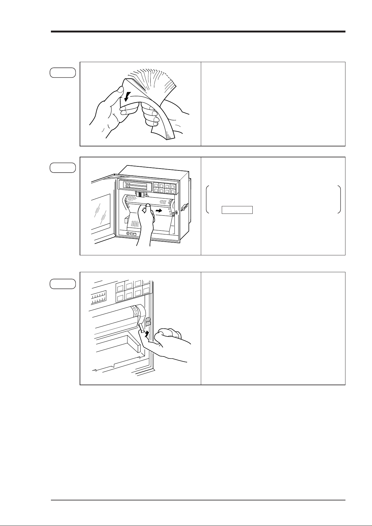
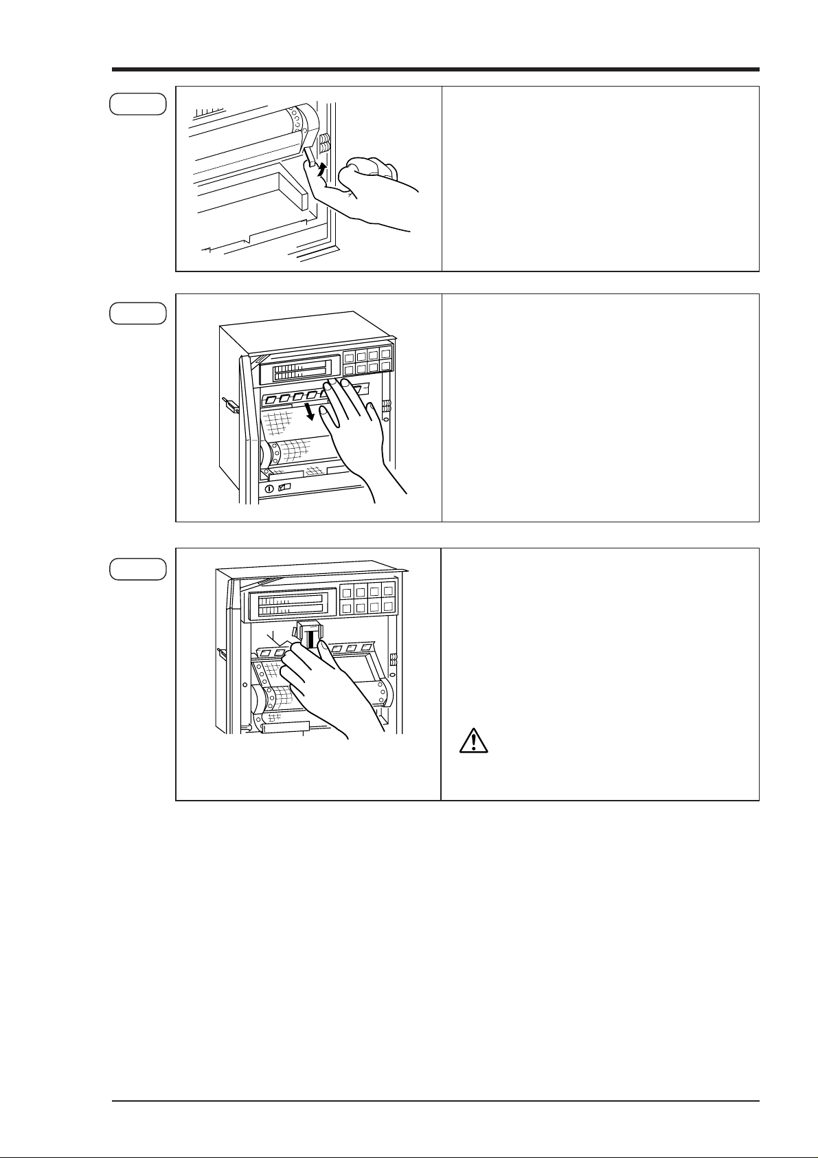
5.1 Loading chart paper
Step 1 Riffle and loosen the recording paper so as to
prevent overlapping feed.
Step 2 Open the front flap, push the paper hold-down
roller to the right and detach it.
To replace chart paper while recording is in
progress, carry out the above after pressing
the RECORD key to stop recording.
Step 3 Raise the lever that is on the right.
This releases the lock, the paper feeder moves
downward and paper holder can be seen.
5 - 1INP-TN4PHAV-E
Page 19
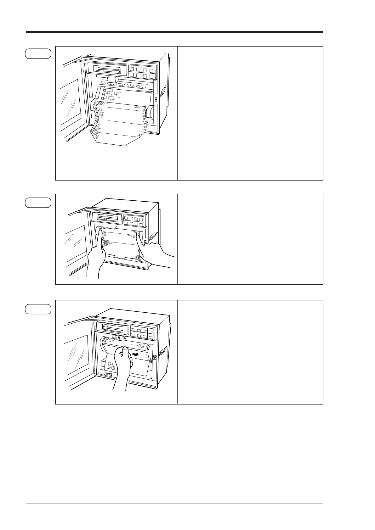
Step 4 With round holes (small holes) in the recording
paper located on the left-hand side, set the recording paper so that its leading edge with both
corners cut off comes to this side. Then insert
the leading edge into the container with the printing face located upward.
Butt the recording paper to the left-hand end and
set the recording paper in this position at this
time. Furthermore, be careful so that the recording
paper will not be located aslant. In addition, droop
the first two or three folds of the recording paper into the recording paper receiver.
Step 5 Press the chart paper so that its holes engage with
the sprockets and then, without further adjustment, return the paper holder to its original place.
Make sure that the chart paper does not lift up.
Note: If chart paper lifts up and contacts the re-
cording head, it can prevent ink coming
out. It can also cause improper paper feed.
Step 6 Return the paper hold-down roller to its original
position.
Check to make sure that the chart paper is straight
and that its holes are properly engaged with the
sprockets.
In order to prevent the chart paper slipping to the
left or right,
per folds into the middle of the paper catcher.
Turn the power supply switch on.
position equipment so that the pa-
5 - 2 INP-TN4PHAV-E
Page 20

Step 7 Press the FEED key and check that the chart
paper is fed out smoothly. (Feed out about 2 folds
of paper.)
<If the paper is not fed out smoothly, go through
the procedure from Step 2 again.>
Note 1: Selection of chart paper
The chart paper greatly affects the quality of the printed recording and it is also related to problems such as paper jamming, etc.
Please be sure to use the pure-quality chart paper specified by us.
Chart paper type:PEX00BL1-1000B (100 equal divisions, no time lines)
Note 2: Use of the recorder after it has been left unused for a long time
If the recorder is left unused for a long time with chart paper still in the main unit, the paper 'packs
down' and if the recorder is used straightway there can be problems of paper jamming, etc.
If you use the equipment after it has been left unused for a long time, first press the FEED key to
feed out 2 to 3 folds of the paper.
Reference 1: Chart paper length
The chart paper is approximately 20m long. This permits about 31 days continuous printout at a paper feed speed of 25mm/h.
Reference 2: Chart paper end mark
The amount of chart paper remaining is indicated by digits (units : cm) on the right-hand
side of the paper. When there is only a small amount left, red letters appear on the righthand edge.
If the recording paper runs out completely, a recording paper end indicator displays 'Chart
end' in the display section and recording automatically stops.
5 - 3INP-TN4PHAV-E
Page 21
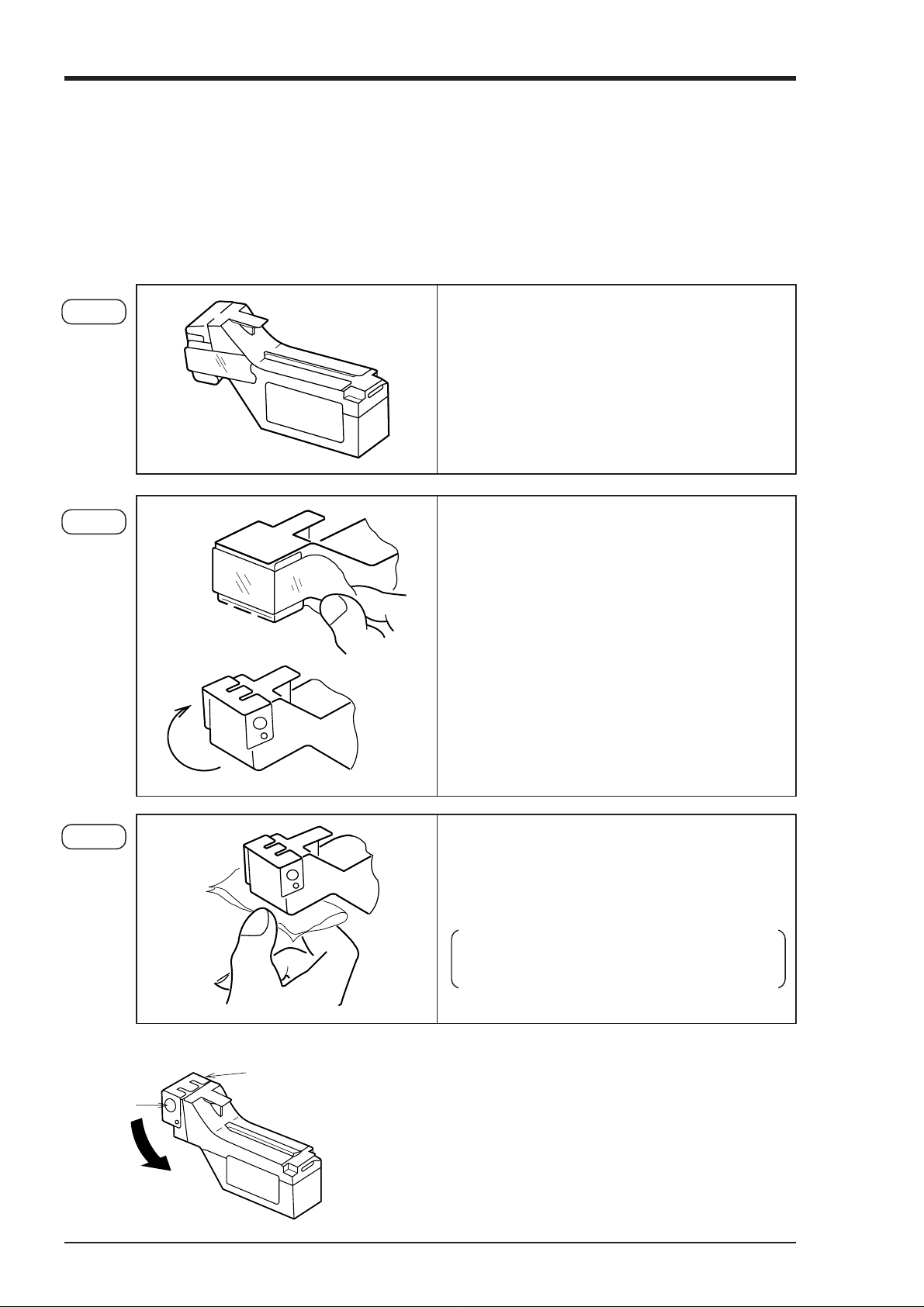
5.2 Recording head installation (replacement)
The recording head has ink and a head for recording in an integral assembly.
If the ink gets used up or if it happens that there is a fault, the head can easily be replaced.
As the recording head is a very delicate element, please carefully read the 'Precautions" that are noted
later and handle the head with care during replacement work.
Step 1 Get the recording head ready by taking it out of
its aluminium pack.
Step 2 Tear the tape.
Open the cap by turning it in the direction indicated by the arrow.
(If the head is not going to be used for a long
time, close the cap back in its original position.)
The cap is integral with the head unit. Turn it
about 180° until it stops against the tope of the
head.
Step 3 Lightly press the nozzle surface (the surface
from which ink is discharge). Make sure that
the cloth is properly impregnated with the 4
colors blue, red, yellow and black.
First press the cloth against the surface for 2
to 3 second; if the 4 colors ooze out, it is OK.
How to close the cap
Cap
Stopper
• Turn the cap in the direction indicated by the arrow and
press it firmly until it is retained by the stopper.
• Ink may leak out if the cap is not properly in place.
5 - 4 INP-TN4PHAV-E
Page 22
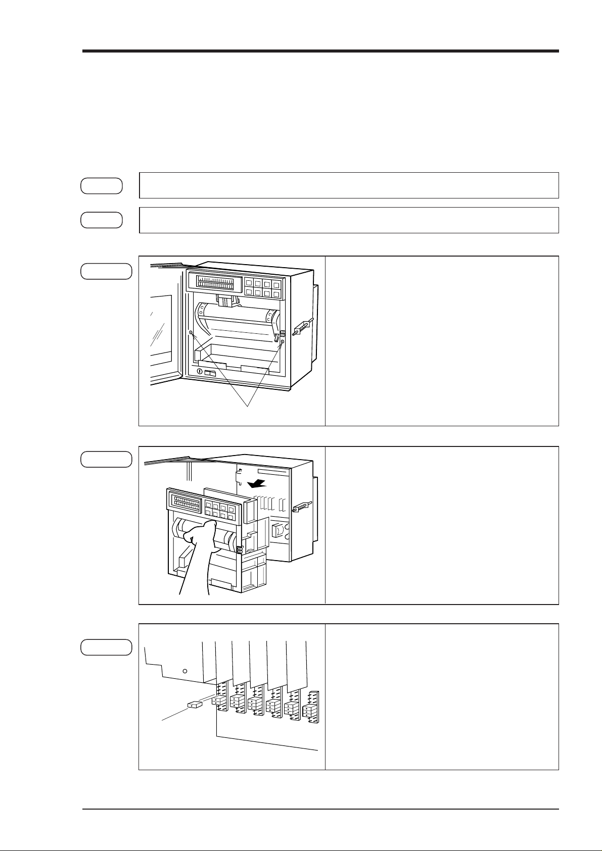
Step 4 • If recording is in progress, stop it by pressing
the RECORD key.
• Raise the lever that is on the right. This releases the lock comma only, the recording paper feed section pulls forward an recording paper holder can be seen.
Step 5 Push the chart paper hold-down plate spring
down.
Step 6 Hold the recording head horizontal, line it up
with the carriage in the main unit slide it in
slowly and press it firmly until it does not go in
any further. Take care not to bang the nozzle
surface of the hand.
Also, avoid touching the nozzle surface with your
hand.
Do not touch the connector at the rear
CAUTION
of the carriage to avoid the risk of minor electric shocks.
5 - 5INP-TN4PHAV-E
Page 23
Step 7 Move the chart paper hold-down plate spring
back up to its original position.
(Check that the plate spring is not contacting the
recording head.)
Step 8 Return the chart paper holder to its original setting.
The above completes installation of the recording head.
The recording head is a consumable part. Replace it with a new one when the ink it contains is used up.
Recording head replacement
Draw out the recording head in the manner that is opposite to what is described in Step 6 of the
recording head setting procedure, and place it with a new recording head.
Always carry out the following procedure after replacing a recording head.
(1) Setting the ink monitor
Perform the following keying actions in order to get correct performance of the ink dry-up warning-detection function.
As in "Clearing the ink monitor' of Section 7.16, press the SELECT key to give an 'Ink monitor
clear" display.
INK MONITOR CLEAR
NO
↓
INK MONITOR CLEAR
YES
(2) Test patter print-out
Print out a test pattern to check that normal recording is possible. Set Section 6.3 for the way of printing
out a test pattern.
(3) Adjustment of analog trend recording positions
Referring to Section 9.2, readjust the zero and span on the recording paper.
Press the key to change the flickering "NO" to "YES".
Next, press ENTRY the ENTRY key.
This completes the setting.
Press the DISPLAY key to return to a data display
5 - 6 INP-TN4PHAV-E
Page 24

Precautions in handling recording heads
Note 1: If recording is halted and the recorder is not used for a long time
Carry out the following in order to prevent jamming and drying-up of the ink.
Remove the recording head from the main unit, make absolutely sure the cap is closed
properly and store the head in a cool, dark place (average temperature 5 to 30
If the head is left installed in the recorder:
Do not switch off the power to the recorder and do not close the cap.
* Periodically, there is an automatic discharge of ink to prevent drying-up.
Leave the recording paper in place in the recorder.
If it is not possible to keep the power switched on, make sure that the cap is closed.
In this case, follow Step 4 and Step 5 of 'Recording head installation' to lower the recording
paper holder and hold-down plate spring and tighten the cap.
Note 2: At the start of use of a recording head
If you are starting to use a new recording head or if the recorder has been left unused for a long time,
always wipe the head's nozzle surface lightly with the accessory cloth and check that the 4 colors black,
blue, red and yellow ooze out properly into the cloth. (See Section 5.2.) Also, after normal recording
is possible. See Section 6.3 for the way of printing out a test pattern.
When the working environment is 15°C or less, perform print-out of "test pattern" after period of
several minutes has elapsed since the recording head was mounted. (The recording head has a built-in
heater.)
°C).
Note 3: Handling recording heads
•Do not knock or shake recording heads as this can cause faults.
• The inks are not harmful but they are very difficult to remove if they adhere to the skin or to clothes,
so handle heads carefully in order to avoid staining. Also, do not disassemble them.
• If, by accident, it happens that ink gets into your eyes, wash thoroughly with water as an emergency
measure and then immediately consult a specialist doctor.
• This product is intended to be used where are not dusty.
• Be sure to start to use the product soon after opening package. (Be sure to finish using this within 1
year after opening)
Note 4: Storage of recording heads
• When they are delivered, recording heads are in aluminium packs.
If you are not going to use a head straight-away, leave it sealed and store it in a cool, dark place with
an average temperature of 5 to 30°C.
• Storage period: 1year and half after purchased.
5 - 7INP-TN4PHAV-E
Page 25

Note 5: Shipping of recording head
• Do not ship the unit recording head after the aluminum pack was opened up.
If it is necessary to ship the unit recording head under avoidable circumstances, be sure to close the
cap, and ship it as contained in a boxboard in the state where vibration and impact are eased using
cushioning materials.
• Always close the cap if you are transporting a head while it is still installed in the recorder main unit.
Note 6: If the ink is not sprayed.
(1) Hold the recording head with turning the nozzle surface down-
ward and push the side strong till spilling two drops.
(2) Absorb the standing ink on the nozzle surface with the cloth at-
tached.
(3) Hold the cloth to the nozzle surface again to find all colors flowed
onto cloth.
* When working environment is 15°C or less, perform print-out
of "record" or "test pattern" after a period or several minutes
has elapsed since the recording head was mounted. (The recording head has a built-in heater.)
Reference: Ink consumption
This varies depending on the conditions of use but with a chart speed of 25mm/h and recording of
constant input, the amount of consumption is as follows.
About 1 year..............................in the case of 1, 2, 3 continuous records
About 6 months.........................in the case of 6 continuous records
About 3 months.........................in the case of 12 continuous records
An ink dry-up warning-detection function produces a warning display in the display section and a
warning print-out the recording paper.
(See Section 11.12 for an example of print-out.)
5 - 8 INP-TN4PHAV-E
Page 26
5.3 Changing the type of input signals
This recorder is a multi-input type which permits the input for any channel to be changed to thermocouple, resistance bulb or DC voltage input.
Follow the procedure described below if you with to change the type of input signals subsequent to
purchase.
Step 1 Turn off the power.
Step 2 Open the front flap and remove the main unit in the manner shown in the drawings below.
Step 2-1 Loosen the lock screws on the left and right and
remove them.
Lock screws
Step 2-2 Grip the paper feed frame and pull it firmly to-
wards you. This detaches it from the main unit.
Step 2-3 Change the settings of the pins for individual
channels on the internal printed circuit board.
(See the method of changing pin positions on the
next page.)
* If there are not enough pins, use the accessory
Input signal
setting pins
input signal setting pins.
*Use pliers, to remove the insert pins.
5 - 9INP-TN4PHAV-E
Page 27
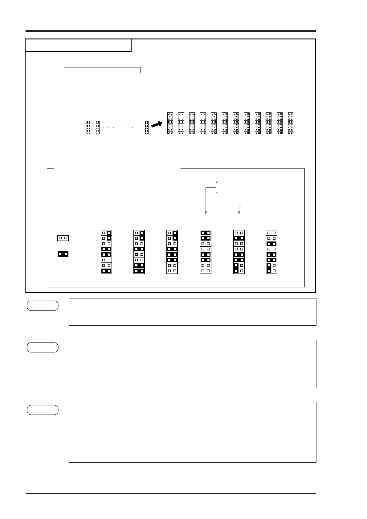
Method of changing pin position
Large PC board installed in deepth of the case.
CH6 CH5 CH7
Changeover pins
(maximum 12)
Pin position for different types of inputs
Correspondence between pin line-up
and input channels
CH6
54321121110 9 8 7
Pin setting is required in correspondence
with types of inputs for each channel.
4 to 20mA DC at input
10 to 50mA DC at input
The set position is as shown below.
1 to 5V DC at input
MAX.
Thermocouple
Resistance
bulb
±
50mV
MAX.
±
500mV
MAX.
±
5V
MAX.
±
50V
OPEN
SHORT
Step 2-4 After completing the change, push the main unit back into its original place and fix it
with the left and right lock screws.
Step 2-5 Change the input terminal wiring to make it correspond to the new input signal type.
For DC voltage input, provide the input terminals with shunt resistors.
Example: In the case of 4 to 20mA DC input, fit the separately sold shund resistors
(10Ω) and set to ±500mV range input pin positions.
Step 2-6 Refer to Section 7.8 and carry out front-panel keyboard operations in order to change
setting in correspondence to change types of input signals.
[Note] DC current input is converted into voltage by shunt resistor (10Ω):
In 4 to 20mA DC : 40 to 200mV DC range
In 10 to 50mA DC : 100 to 500mV DC range
5 - 10 INP-TN4PHAV-E
Page 28

6. OPERATION AND ACTIONS
6.1 Before running the equipment:
Check the following points before starting operation.
1. Recording paper, recording head installation
(1) Loading chart paper....................................................... See Section 5.1
(2) Installation of recording head........................................ See Section 5.2
2. Wiring
(1) Input terminals .............................................................. See Section 4.2
(2) Alarm terminals (option) ............................................... See Section 4.2
(3) Power supply, ground terminals.................................... See Section 4.2
3. Do the input types and channels match?
(1) Type specification ......................................................... See Section 1.3
(2) Changing the type of input terminals ............................ See Section 5.3
6 - 1INP-TN4PHAV-E
Page 29

6.2 Power switch-on and states
(1) Open the front flap.
(2) The power supply switch is at the above left; switch it on.
(1) Initial switch-on of power
↓
—
↓
The recording head moves slowly to the left-hand end (the 0% side).
↓
When the 0% point is detected, the recording head moves to a position that is
about 50mm from the left-hand end and stops.
↓
Ch1. 100°C
(2) If the power is switched off while recording is stopped and switched on again:
The state becomes 'Recording stopped'.
(3) If the power is switched off during recording operation and switched on again:
The state becomes 'Recording in progress'.
Recording in progress
↓
Power supply cut off
↓
Display disappears Recording stops
↓
Power turned on again
↓
(A cursor appears in the upper left of the display section.)
The input data and Tag No. are displayed in the display section.
(No recording takes place.)
—
↓
The recording head moves slowly to the left-hand end (the 0% side).
↓
When the 0% point is detected, the recording head moves to a position that is about 50mm
from the left-hand end (0%), moves back again to the left-hand end and is on standby
↓
Ch1. 100°C
Record ON
(Cursor appears in top left of display section)
The input data is displayed in the display section and recording restarts.
6 - 2 INP-TN4PHAV-E
Page 30

6.3 Test pattern print-out
(1) Open the front flap, switch the power supply switch on the press the SELECT key.
(2) Pressing the SELECT key several more times results in the following display.
List = 1
Parameter list
(3) Press the
When the ENTRY key is pressed, the following test pattern is printed out.
(4)
• Check that there is a complete recording in each color.
If the colors do not come out or are blurred, follow the procedure 3 of Section 5.2 to clean the
recording head nozzle surface.
key twice; this gives the following display.
List = 3
Test pattern
6.4 Actions during operation
(1) Stopping and starting recording operation ( RECORD key)
• Recording is alternately started and stopped each time the RECORD key is pressed.
Ch6 315°C Ch6 315°C
Record ON
When recorded When stopped
(2)
Digital print-out (instantaneous values) ( LIST key)
Record sample
• Measured values can be printed out any time during operation.
• Pressing the LIST key results in a digital print of the time at which the key was pressed and the
measured values and units of all the channels at that time.
• Analog trend recording is stopped during digital printing.
• Completion of digital print-out is followed by a return to analog recording.
• To stop printing during operation, press the LIST key. This restarts analog trend recording.
• "–" (hyphens) are printed for a channel for which skip has been set.
6 - 3INP-TN4PHAV-E
Page 31

(3) Chart paper fast feed ( FEED key)
To effect fast feed regardless of recording, press the FEED key.
•
• The speed is 3mm/s during the first second that the key is held depressed and goes to 8mm/sec
after the elapse of 1 second.
•
When the FEED key is released, there is a return to the set speed.
Note: If you press the key while holding the FEED key depressed, the recording paper is
moved backwards (a maximum of 25mm).
(4) Changing the display mode (DISPLAY key)
• Display modes can be selected at any time pressing the DISPLAY key during operation.
•An under-bar appears at the upper left of the channels 1 to 6 simultaneous display panel for
instantaneous and multipoint display, and at the lower left of the channels 7 to 12 simultaneous
display panel.
• There are the following changes in the display mode each time the DISPLAY key is pressed.
Measured values
Multipoint sequential display
DISPLAY
Measured values
One-point continuous display
DISPLAY
Measured values
Multipoint sequential display
DISPLAY
Measured values
Multipoint sequential display
DISPLAY
Time display
Ch1 150°C
Record ON
One-point continuous
display mark
Ch6* 315°C
Record ON
ch1 ch2 ch3
0.001
-
3.45
ch4 ch5 ch6
ch7 ch8 ch9
2.345
100.0
ch10 ch11 ch12
'90 10/30 11:30
130.0
0.000
-3.000
24.5
50.00
1.15
50.01
0.001
Record ON
There is sequential display
starting from ch 1.
Only specified channel is
displayed.
,
To change channels, get a
channel No. by pressing
the or key.
Channels 1 to 6 are display
simultaneously.
Channels 1 to 12 are
display simultaneously.
Time image does not appear on
the display panel when the
recording points are less than 6.
The current time is
displayed.
DISPLAY
Note: No Record ON is displayed
when recording is stopped.
6 - 4 INP-TN4PHAV-E
Page 32

6.5 Displays and print-outs on detection (cancellation) of alarms
(1) If an alarm is detected the display section gives a display as follows.
Example of alarm display
Example: Upper section Ch 2 measured value
Ch2 123.5°C Lower section Alarm in Ch 6
Alarm Ch6 H ALM1 H alarm, relay No. 1
This display continues until it is cancelled.
(2) When an alarm detected and cancelled, the relevant details are printed on the right-hand side of the
chart paper.
On detection: The time of detection, channel No., type of alarm, relay No.—
On cancellation: The time of cancellation, channel No., relay No.—Print-out colour: Black
Typical alarm display
(1) H alarm occurred with Ch 1 No. 1.
Relay No. 1, occurred time 14:48.
(2) H alarm of Ch 1 No. 1 was canceled.
Relay No. 1, canceled time 14:56.
Print-out color: Red
(3) If an alarm is detected or a cancellation is made during data print-out or list print-out, the alarm
print-out takes place after completion of the data or list print-out.
(4) Up to a maximum of 30 alarm detection cancellation information can be stored and sequentially
printed out, but if the storage capacity is exceeded because of a large number of detections/cancellations in a short time, information in the overflow portion is discarded and cannot be printed out.
6.6 Displays and print-outs on occurrence of burnt-out
(1) If a thermocouple or resistance bulb wire breaks, the relevant details are indicated in a display
Example of burn-out display
Ch6 Burn-out
Record on
Ex.: Burn-out in Ch 6
0.1 -4.00 0.01
1.00 2.00 Burn-out
Note: The trend record is switched to the maximum value side of the record range.
(2) If a burn-out occurs, details of the burn-out are printed on the right-hand side of the chart paper.
(Print-out color : Red)
Example of burn-out print-out
Ch1 Burn-out 11:52 Time of occurrence : 11. 52
Channel No. :1
6 - 5INP-TN4PHAV-E
Page 33

6.7 Over-range, under-range display and abnormal input display
In all cases, for thermocouples, resistance bulbs and DC voltage input, there is a reference range for
input signals. If input is outside preset range an 'Over' or 'Under' display is given.
Example of over/under display
Ch2 over °C 0.0 over 5.00
Record ON 6.00 under 3.00
Ch 5 under °C
Record ON
In the case of voltage input, input error display appears when the input signal line was broken or when
an over-input signal or an under-input signal was input.
Typical input error display
Ch3 Error Error Error 3.0 4.0
Trend record 5.0 6.0 7.0
6.8 Display and record when chart paper runs out (“Chart End” display)
When there is no more chart paper, a display as follows is given and recording automatically stops.
Display of measured values and alarm monitor continue.
Ch6 123.5°C
Chart end
6.9 Display and record when the recording head ink is low (“Ink Out” display)
(1) A display as follows is given on the chart paper when the amount of remaining ink is low.
'Ink Out' is displayed in the display section.
Example
Ch6 123.5°C
Ink Out
(2) 'Ink Out' is printed on the right-hand side of the chart paper.
< Print-out color : The color of the ink whose remaining quantity is low >
Note: Ink Out' is output when the amount of ink remaining is about 10% or less and so recording
can continue for a little while even if 'Ink Out' is output.
6 - 6 INP-TN4PHAV-E
Page 34

6.10 Display when data backup batteries need to be replaced (“Battery End” display)
When the voltage of back-up batteries becomes low, a display indicating that they need to be replaced
is given.
'Battery End' is displayed in the display section.
Example
Ch6 123.5°C
Battery End
Replace the batteries promptly when a 'Battery End' display appears page 8-3.
6.11 Display of fault in recording head carriage (“Carriage Alarm” display)
If a fault in the recording head carriage occurs and the recording head can no longer function normally,
a fault display is given and the recording operation stops.
Example
Ch6 123.5°C
Carriage Alarm
If a 'Carriage Alarm' display is given, check the following points.
(1) Is foreign matter adhering to the recording head carrier shaft ?
(2) Is the wire that drives the recording head broken or slack ?
(3) Has the recording paper lifted up and come into contact with the recording head ?
(4) Is the recording head set in place correctly ?
After eliminating the cause of the fault, switch on the power supply of the main unit.
6.12 Order of priority of state displays
If the items noted below occur simultaneously, the corresponding displays are given in the indicated order.
1. Chart end
2. Carriage alarm
3. Ink end
4. Battery end
5. Alarm
Note: When the state displays 1 and 2 above are given, the SELECT key is inoperative.
However, the DISPLAY and FEED keys are operative.
6 - 7INP-TN4PHAV-E
Page 35

7. SETTING AND CHECKING PARAMETERS
7.1 Setting and checking
(1) The parameters at the time of shipment are as indicated in the table below.
Recorder operations (displays, analog trend recording) can be effected simply by switching the
power on without making any adjustments, but you can set the parameters you require.
(2) The record ranges are multirange and it is necessary to set the required ranges.
(3) Alarms, Tag Nos., message, scaling, square root extraction and subtract calculation, daily report
and totalize functions are not set. Please set these if they are required. Input filters are set to 3
seconds.
(4) After setting up parameter, it is recommended to print out parameter list and retain parameter in
order to find out setting contents later.(refer to the Item 7.11 regarding printing out parameter list.)
Note: If you set parameters, always do so after setting chart paper in place. If chart paper is not
installed, the SELECT key is inoperative.
7 - 1INP-TN4PHAV-E
Page 36

(1) Values of parameters at the time of shipment (initial values)
Parameter name
Pass code
Main chart speed
Sub-chart speed
(option)
Alarms
Recording mode
Record range
Input selection
TAG No.
Message print
List print-out
Daily report
Totalize
T-link transmission
(option)
State at time of
shipment (initial values)
(Cancelled)
25mm/h
25mm/h
No. 1 to 4: NO
Set value: 0
ALM: 0
Trend recording
Periodic print-out: ON
Scale print-out: ON
Recording format:
Standard
Thermocouple system:
0 to 1200°C, K
Resistance bulb system:
0 to 500°C, Pt
DC voltage system:
DC -5 to 5V
Thermocouple: K
thermocouples, °C
Resistance bulb:
Pt 100, °C
DC voltage: V
Input filter: 3 seconds
Scaling: OFF
Rooter: OFF
Logarithmic
calculation: OFF
Subtract calculation: OFF
Blank
Blank
Print position: 0mm
Print timing: Manual
—
Function: OFF
Automatic print-out: ON
Start time: 00:00
End time: 00:00
Function: OFF
Automatic print-out: ON
Start time: 00:00
End time: 00:00
Station No.: 1
Remarks
Setting range: 0 to 9999
Setting range: 5 to 1500mm/h
Setting range: 5 to 1500mm/h
Changed by external contact input
4 kinds and 4 points, L, H, RH and RL, are
available for each channel (relay output:
option).
Trend recording/logging recording selection
Periodic digital print-out on/off selection
Fixed interval scale lines, digits, units print-out
selection of ON/OFF
Standard, auto-range recording, zoom records,
zone recording selection
Specification of record range
Input type specification,
°C, °F specification
mV, V' specification
Setting range: 0 to 900 seconds
DC voltage input scaling can be set (working
values, units)
DC voltage input rooter (square root extractor)
can be specified
Recording of differences between channels can
be specified
Up to 8 alphanumeric characters
10-message, alphanumeric: Within 16
characters
Parameter list print-out, scale print-out, test
pattern print-out, daily report, totaling list
Daily report function on/off selection, start
time selection
Daily report list automatic print-out on/off
selection
Daily report operation on/off setting for each
channel
Totalize function on/off selection, start time
selection
Totalize list automatic print-out on/off selection
Totalize operation on/off setting for each channel
Specified if there is connection with parent
CPU
Skip/copy
setting
Method of setting
checking
Section 7.3
Section 7.4
Section 7.4
Section 7.5
Section 7.6
Section 7.7
Section 7.8
Section 7.9
Section 7.10
Section 7.11
Section 7.12
Section 7.13
Section 7.14
Time setting
Ink monitor clear
Recording paper
illumination lamp
(option)
Current time setting
NO
ON
Display in the order, Yea, Month, Day, Hours,
Minutes
Setting of ink end warning-detection function
Always set to clear (YES) after recording head
replacement
Set to "OFF" to turn out the recording paper
illumination lamp
Section 7.16
Section 7.16
Section 7.17
7 - 2 INP-TN4PHAV-E
Page 37

7.2 Outline of procedure for setting parameters
Data display mode
DISP SEL
Pass code
SEL
Main chart
sped
SEL
Sub-chart
speed
SEL
Alarm Section 7.5
SEL
Recording
mode
SEL
Record range
SEL
Input
selection
T A G No.
Input type unit
Input filter
SEL
SEL
Message print
SEL
DISPLAY
If pass code specification is 0, this display is
skipped.
Section 7.4
<option>
Section 7.4
ENT
Logging
Trend
Section 7.6
ENT
Section 7.7
Section 7.8
Setting
when copied
DC
voltage
ENT
Section 7.9
Section 7.10
Key
Description of keys
SEL : SELECT key
•
Whatever the current state, operation moves to the next mode when this key is
pressed.
•
ENT : ENTRY key
If this is pressed when data is to be registered following specification or when
registration is not needed, there is a move to display of the next set item.
•
DIAPLAY : Whatever the current state, there is a return to the data display mode when this
key is pressed.
•
: These serve for specification and selection of data.
•
To return to the beginning of parameter settings, press the DISPLAY key once and then
press the SELECT key.
ENT
ENT
ENT
Measure
range
Record format
Standard
Auto-range
Zone
Zoom
ENT
Rooter
Engineering
range
ENTENT
ENT
Units Subtraction
Logging interval
Periodic print-out
scale print-out
When OFF
Scaling
ON/OFF
In the case of thermocouples, resistance bulbs
ENT
List
print-out
Daily report function
Parameter list
Scale print-out
Test pattern
SEL
SEL
Section 7.12
Totalize function Section 7.13
SEL
<option>
Transmission Section 7.14
SEL
Time setting
Ink monitor
clear
Illumination
lamp ON/OFF
Pass code
specification
SEL
SEL
SEL
SEL
Section 7.15
+
Section 7.16
<option>
Section 7.17
Section 7.3
SELFEED SEL SEL SEL
Daily report list
Totalize list
Message print
Back lash
calibration
Section 7.11
Record zero-span
calibration
Section 9 Application
External output
of setting error
To data display mode
DISPLAY
Alarm latch
SEL
PV shift
Unit
preparation
SEL
7 - 3INP-TN4PHAV-E
Page 38

7.3 Pass code setting
Explanation
If the pass code is set to a value other than 0, it is necessary to enter the correct pass code before
changing parameter setting pass code. A numerical value is specified on the screen by means of the
and keys and is input by the ENT key. If this value is the same as the previously set pass
code, there is a move to a display of the next parameter.
If the pass code is incorrectly specified, the keys are locked as follows.
Preset pass code < 5000
Only the list display is given and it is not possible to change parameter settings.
Preset pass code ≥ 5000
The list display is given, but list print-out is inhibited.
Furthermore, RECORD , LIST , and FEED keys on the front panel are locked.
At the time of shipment, the pass code is set to 0 and the key lock is released.
If the pass code is 0, the pass code display is skipped.
Key actuation Setting of the pass code
(example)
Key operation Explanation Display
SEL Press the SEL key several times to bring up the
pass code specification display.
ENT Press the ENT key to register the value. When it
DISP Press the DISP key to go to the data display
SEL Press the SEL key to bring up the pass code
ENT Press the ENT key to effect registration.
Press the keys to specify the value you want
for the pass code (specification range 1 to 9999).
has been registered, there is a move to the next
parameter.
mode.
input screen.
Press the key to give the value of the pass
code that has been specified.
Note: If the value input at this time is different
from the pass code that has already been
specified, the list screen comes up (key
lock state).
In this case, it is not possible to clear the pass
code, so go through the process again from
the beginning and input the correct value.
If the value input is the same as the pass code
value, there is a move to the next parameter.
PRESET PASS CODE
■■■■
PRESET PASS CODE
■■■■
MAIN CHART SPEED
■■■■ mm/h
ch1 123.4°C
PASS CODE =?
■ 0
PASS CODE =?
LIST = 1
PARAMETER LIST
MAIN CHART SPEED
■■■■ mm/h
7 - 4 INP-TN4PHAV-E
Page 39

7.4 Setting the chart speed (main chart speed/sub-chart speed)
Explanation
• Main chart speed: This is the procedure for setting the chart speed in normal operation.
The setting range is 5 to 1500mm/h. (Can be set in 1mm/h steps.)
• If the case of a continuous recording type, if the chart speed is too fast, the result is dashed
line recording instead of continuous recording. (As a general criterion, 300mm/h or more)
• Please note that the following digital print-outs are not possible if the chart speed of continuous
recording type is 301mm/h or more, that of dot recording type is 51mm/h or more.
'Periodic print-out' 'Scale print-out' 'Message print-out' 'Alarm print-out' 'Parameter print-out' 'Ink
Out print-out'.
However, a 'Scale print-out' 'Message print-out' can be made manually.
See Section 7.11.
• The sample time in continuous recording varies depending on the chart speed
Sample time =
Chart speed (mm/h)
(But not faster than 3 seconds.)
Example:
Chart speed (mm/h) 10 20 25 50 100 150
Sample time 45 Repeated 22, 23 20 9 Repeated 4, 5 3
• Sample time of intermittent recording type is fixed to 30 seconds.
Key actuation Changing the normal chart speed of 25mm/h to 20mm/h
(example)
Key operation Explanation Display
SEL Press the SEL key twice to display the main
chart speed. (In case where pass code =0)
450
MAIN CHART SPEED
25mm/h
Press the key to set to '20'
ENT Press the ENT key to effect registration.
There is a move the display of the next parameter.
MAIN CHART SPEED
20mm/h
SUB CHART SPEED
25mm/h
7 - 5INP-TN4PHAV-E
Page 40

Explanation
Sub-chart speed: This is the chart speed when its rate is controlled by an remote control signal.
The setting range is 5 to 1500mm/h. (Can be set in 1mm/h steps.)
The optional external control unit is necessary.
Key actuation Changing the recording paper feed of speed 100mm/h to 150mm/h by an
(example) external control signal (DI)
Key operation Explanation Display
SEL Press the SEL key 3 times to display the sub-
chart speed. (In case where pass code = 0)
Press the key to set to '150'.
ENT Press the ENT display moves to next parameter.
SUB CHART SPEED
100mm/h
SUB CHART SPEED
150mm/h
ALARM ch1 HH=OFF
0°C ALM0
7 - 6 INP-TN4PHAV-E
Page 41

7.5 Setting alarms
Explanation
• Channel No.: Set the No. of the channel in which alarms are to be set.
•Alarm type: The 4 types H, L, RL, RH (H, L, RL and RH can be set on the same alarm.)
When No. is selected, alarm operation is stopped. (There is no alarm display,
print-out or alarm output.)
• Alarm set values: Set to engineering values (absolute value alarms).
• ALM: Set option alarm unit relay Nos. (1 to 12; no output with 0).
Key actuation Change of channel No. 1
(example) L → H30°C →80°C OFF→ON ALM 1→6
Key operation Explanation Display
SEL Press the SEL key several times to give the
alarm display. (In cases where pass code = 0)
ENT Select channel No. to change and press the ENT
key.
Press the key to change "L" to "H" and press
ENT the ENT key to effect registration.
Press the key to change the set value
ENT from "30°C" to "80°C" and press the ENT key to
effect registration.
Press the key to change the ALM No. from
ENT "1" to "6" and press the ENT key to effect
registration.
(When the ENT key is pressed, the channel No.
flashes and the setting is completed. Follow the
same procedure for setting in other channels.
ALARM ch 1L=OFF
30°C ALM1
ALARM ch 1L=OFF
30°C ALM1
ALARM ch 1H=OFF
30°C ALM1
ALARM ch 1H=ON
80°C ALM1
ALARM ch 1H=ON
80°C ALM6
Note: RH, RL ............ High/low limit alarm for variation rate. Alarm is emitted when variation rate
per input exceeds the set value of each alarm.
7 - 7INP-TN4PHAV-E
Page 42

7.6 Setting the recording mode
The following recording modes can be set in this section.
(1) Logging recording (logging)
(2) Periodic print-out
(3) Scale print-out
(4) Auto-range recording (auto-range)
(5) Enlarged/reduced recording (zoom)
(6) Zone recording (zone)
Setting procedure
RECORD MODE
logging
RECORD MODE
Trend
ENT
PER. PV LIST = ON
SCALE PRINT = ON
Use the and keys to select
the record format (standard, auto-range,
zone, zoom).
ENT
LOGGING INTERVAL
ENT
RECORD FORMAT
NORMAL
30 min
ENT
Use the and keys to specify
whether or not the range is made
auto-range for each channel.
REC
RECORD FORMAT
AUTO-RANGE
ENT ENT ENT
AUTO-RANGE
Ch 1 = ON
RECORD FORMAT
ZONE
ZONE PART COUNT = 3
Ch = 6 ZONE
Specification of number of
zone divisions (1-4)
Use the and keys to
specify
the zone No. or
the channel No.
RECORD FORMAT
ZOOM
ZOOM
Ch1 OFF
Channel No. to be
zoomed is set by
and keys.
ENT
Boundary value 1: 0.0°C
Chart position: 0%
Boundary value 1
and chart position
% are set by
and keys.
ENT
ENT
DISP
Measured value display
Start of recording
Boundary value 2: 0.0°C
Chart position: 0%
Boundary value 2
and chart position
% are set by
and keys.
RECREC
Move to display of
next parameter
7 - 8 INP-TN4PHAV-E
Page 43

(1) Logging recording (logging)
•In this case, there is no analog trend recording but a record of data (the time channel Nos., measured
values, units) is produced at specified intervals of time (10 to 60 minutes can be specified.)
• If there is detection or clearing of an alarm during logging print-out, this is printed on the right-hand
side of the recording paper. (Example of print-out: Section 11.9)
(2) Periodic print-out
• The following items are printed out at set intervals in depending on chart speed.
Time line, time, chart speed, channel Nos., measured values, engineering units.
• This print-out is effected alternately with scale print-outs.
• It is not effected if the periodic print-out is set to "OFF".
(3) Scale print-out
• Scale lines, digits, unit and Tag Nos. are printed out at set intervals.
•This print-out is effected alternately with periodic print-outs.
• It is not effected if the scale print-out is set to "OFF".
• If both scale print-out and periodic print-out are set to "ON", the print-outs are effected alternately at
set intervals.
Periodic print-out and scale print-out time intervals sub heading
The time intervals of print-outs vary depending on the chart speed.
1. In the case of continuous recording
Chart speed (mm/h) 5 to 9 10 to 19 20 to 39 40 to 79 80 to 159 160 to 239 240 to 320
Print-out time interval 12 h 8 h 4 h 2 h 1 h 30 min 20 min
Chart speed (mm/h) 321 to 480
Print-out time interval 15 min 10 min
When the chart speed exceeds 301mm/h, only the time line is recorded.
Periodic print-out and scale print-out are not effected.
2. In the case of intermittent recording type
Chart speed (mm/h) 5 to 9 10 to 19 20 to 39 40 to 79 80 to 159 160 to 239 240 to 320
Print-out time interval 12 h 8 h 4 h 2 h 1 h 30 min 20 min
Chart speed (mm/h) 321 to 480
Print-out time interval 15 min 10 min
481 to 1500
481 to 1500
When the chart speed exceeds 51mm/h, only the time line is recorded.
Periodic print-out and scale print-out are not effected.
Note: If the time for a periodic print-out or scale print-out arrives while data printing or other list
printing is in progress, the periodic print-out or scale print-out is not made.
If data print-out is started while a periodic print-out or scale print-out is in progress, the
periodic print-out or scale print-out is halted partway through.
7 - 9INP-TN4PHAV-E
Page 44

(4) Auto-range recording (auto-range)
If input outside the record range occurs, recording is effected with the record range automatically changed.
The record range after a change goes 50% of the span to the plus side or the minus side. Note that the
recording span does not change. (Made effective with an ON setting.)
Example: With a 0 to 100°C record range (recording span 100°C)
• If input goes beyond the range in the positive direction, there is a change to 50 to 150°C.
• If input goes outside the range in the negative direction, there is a change to -50 to +50°C.
Note 1: A change in the range is only effected once in a given direction.
Once a range has changed in the positive direction, it does not change again even if the record
range is exceeded again.
Note 2: If the record range changes because it has been exceeded in the positive direction and then input
below the new range in the negative direction there is a return to the original range. (The
reverse also applies.)
Note 3: A mark is printed in black at the right-hand edge of the recording paper when the range changes.
Note 4: There is a record range MAX. value and MIN. value for each type of input.
Consequently, if a change means that a range is going to go beyond the MAX. value or MIN.
value for the record range of the type of input in question, the MAX. value or MIN. value
imposes a limit.
Example: For a K thermocouple 0 to 1000°C record range
• If over-range occurs: change to 400 to 1400°C
• If under-range occurs: change to -230 to 770°C
Note 5:
Auto-range recording cannot be specified simultaneously with zoom recording or zone recording.
(5) Enlarged/reduced recording (zoom)
Within the record range (record range) for each channel, there are three recording scales. This makes it
possible to have an enlarged record in one portion and a reduced record in the other portion.
Example: With a 0 to 100°C record range:
Suppose you want to enlarge 40 to 60°C record in a 10 to 90% range.
(The 0 to 10% range becomes a reduced record of 0 to 60°C, and the 90 to 100% range becomes
a reduced record of 60 to 100°C)
Boundary value 1 = 40°C
Chart position = 10%
Normal recording
Zoom recording
<Reduced>
0
20 40 60 80 100°C
0
40°C
10% 10%
Boundary value 2 = 60°C
Chart position = 90%
60°C 100°C
<Enlarged>
<Reduced>
Note 1: Do not set the normal recording 0% value at the 100% recording position or the normal record-
ing 100% value at the 0% recording position.
If you do, proper operation becomes impossible.
7 - 10 INP-TN4PHAV-E
Page 45

Note 2: If zoom recording is specified, scale print-out digits are printed only for the 4 points 0% and
100% of the record range, and the boundary value 1 and the boundary value 2. (Boundary value
scale digits are printed only if the record position is 15 to 85% and when the difference between
boundary value 1 and boundary value 2 is less than 7%, only the small chart position is printed.)
Example: With a record range 0 to 500°C, the boundary value 1 of 200°C, chart position of 30%,
and the boundary value 2 of 300°C, chart position of 70%.
0.0 200.0 300.0 500.0
Note 3:
(0%) (30%)
(70%)
Zoom recording cannot be specified simultaneously with auto-range recording or zone recording
(100%)
(6) Zone recording (zone)
• The recording width is 180mm and overlap of the records of different channels is prevented by the
provision of recording zones for the various channels.
• Any zone can carry the record of any channel.
• The number of divisions is up to a maximum of 4 zones.
4 zones 3 zones
Zoen 1 Zoen 2 Zoen 3 Zoen 4 Zoen 1 Zoen 2 Zoen 3
Record
range
45mm 45mm 45mm 45mm
Record
range
180mm
Record
range
Record
range
54mm 54mm 54mm
180mm
18mm at the right-hand edge is blank.
18mm
.
2 zones
Zoen 1 Zoen 2
90mm 90mm
180mm
Note 1: For scale print-outs when zone recording is specified, there is a print-out only of scale digits for
the 2 points record range 0% and 100%.
Note 2: During zone recording, alarm print-outs and burn-out print-outs are produced at the right-hand
edge whatever the zone.
Note 3:
Zone recording cannot be specified simultaneously with auto-range recording or zoom recording.
7 - 11INP-TN4PHAV-E
Page 46

7.7 Setting record ranges
Explanation
An individual record range is set for each channel. 'Record range' means the 0% and 100% position
scale on recording paper. If DC voltage input scaling is set and used, set the record range after setting
scaling. If scaling is set, the decimal point position is the same one as set by the engineering value.
Key actuation The record range of channel 1 is changed from 0 to 100°C to -50 to 50°C.
(example)
Key operation Explanation Display
SEL Press the SEL key several times to give the
ENT Since channel No. 1 is selected, press the ENT
ENT from "0" to "-50" and press the ENT key.
ENT press the ENT key.
Type
Thermocouples
Resistance
bulbs Pt100
DC voltage
B
R
S
K
E
J
T
N
W
L
U
PN
JPt 100
recording range display.
key.
Press the key to change the range lower limit
Press the key to change "100" to "50" and
(When the ENT key is pressed, the channel No.
flashes and the setting is completed.
Follow the same procedure for settings in other
channels.)
Table 1 Specifiable ranges record ranges
Reference range
400 to 1760°C
0to1760°C
0to1760°C
-200 to 1370°C
-200 to 800°C
-200 to 1100°C
-200 to 400°C
0to1300°C
0to1760°C
-200 to 900°C
-200 to 400°C
0to1300°C
-200 to 600°C
-200 to 600°C
-50 to +50mV
-500 to +500mV
-5 to +5V
-50 to +50V
Reference range
725 to 3200°F
32 to 3200°F
32 to 3200°F
-328 to 2498°F
-328 to 1472°F
-328 to 2012°F
-328 to 752°F
32 to 2372°F
32 to 3200°F
-328 to 1652°F
-328 to 752°F
32 to 2372°F
-328 to 1112°F
-328 to 1112°F
Specifiable ranges
370.0 to 1790.0°C
-30.0 to 1790.0°C
-30.0 to 1790.0°C
-230.0 to 1400.0°C
-230.0 to 830.0°C
-230.0 to 1130.0°C
-230.0 to 430.0°C
-30.0 to 1330.0°C
-30.0 to 1790.0°C
-230.0 to 930.0°C
-230.0 to 430.0°C
-30.0 to 1330.0°C
-230.0 to 630.0°C
-230.0 to 630.0°C
-55.0 to +55.0mV
-550.0 to +550.0mV
-5,500 to +5,500V
55.00 to +55.00V
ch 1 RANGE
0 to 100°C
ch 1 RANGE
0 to 100°C
ch 1 RANGE
-50 to 100°C
ch 1 RANGE
-50 to 100°C
for record range
698.0 to 3254.0°F
-22.0 to 3254.0°F
-22.0 to 3254.0°F
-382.0 to 2552.0°F
-382.0 to 1526.0°F
-382.0 to 2066.0°F
-382.0 to 806.0°F
-22.0 to 2426.0°F
-22.0 to 3254.0°F
-382.0 to 1706.0°F
-382.0 to 806.0°F
-22.0 to 2426.0°F
-382.0 to 1166.0°F
-382.0 to 1166.0°F
The range -32767 to 32767 (decimal points can be located wherever required) can be specified for the record range
in scaling or difference calculation specifications.
7 - 12 INP-TN4PHAV-E
Page 47

7.8 Setting kind of input, skip, unit, filter, scaling, subtraction
Explanation
The type of input (B, R, S, K, E, J, T, N, W, L, U, PN thermocouples, JPt, Pt, voltage, COM, copy
skip), units (°C, °F, mV, V), filters (time constant) and in the case of DC voltage input, the scaling,
input range, engineering value (scaling value), units, rooters (square root extractors) and logarithmic
arithmetic operation are specified for each channel.
= Explanation of display =
Channel No.
Type of input
Unit (°C, °F, mV, V)
Ch
Filter T=
sec
0 to 900
Note:
*When skip is set as the input type, indication, recording and alarming actions are not performed for
the subject channel.
In the case of
thermocouples,
resistance bulbs
Ch1 K °C
FILTER T=3 SEC
ENT
If OFF
SUBTRACTION
Ch1
Ch0 Ch1
Ch
FILTER T=
In the case of DC
voltage (current)
Ch1 50mV mV
FILTER T=3 SEC
Ch1 SCALING=ON
MEASUR. RANGE
0 to 10.00mV
SQUARE ROOT OFF
Ch1
LOGARITHM OFF
ENT
ENT
ENT
sec
In the case of
transmission input
Ch1 COM
FILTER T=3 SEC
ENT ENT ENT
Set copy
Ch2 COPY
Ch2<=Ch3
To the next channel Next channel
Note:
Data copied by the copy
which has been set.
• Type of input
• Filter
• Scaling
• Subtraction
• Rooter
• Recording range
• Unit
• Zone set value
• Zoom set value
• TAG No.
• Alarm set value
Note:
When skip is set, the
formerly set engineering
value, unit, etc. are reset.
On the occasion of the next
measurement (when an
input type other than skip is
set), set engineering value,
unit, etc. once again.
Skip
Ch1 SKIP
FILTER T=3 SEC
ENT
ENG. VALUE
Ch1
0 to 10.00
ENT
UNIT
Ch1
SUBTRACTION
CODE
Ch0 Ch1Ch1
A=3 B=2
ENT
0-100000 of transmission
input data is converted into
the min. - max. of an
industrial value.
kg/h
7 - 13INP-TN4PHAV-E
Page 48

(1) Setting and changing input signal type
To effect the changes refer to Section 5.3 to change the positions of the setting pins.
Then, use the following parameter specification to specify the correct input signal type.
Example: Changing 5V input signal type of channel 6 to thermocouple input
Ch1 K °C
FILTER T=3sec
↓ ENT
Use the , keys to select channel 6 and press the ENT key.
DC voltageThermocouple Resistance bulb
Ch1 K °C
FILTER T=3sec
Note:
The type of input is displayed in the following order by pressing the key (in reverse order
with key).
K E J T R S B N W L U PN Pt JPt 50mV
↓ ENT
Ch6 K °C
Jumper Setting OK?
(2) Setting and changing the input filter
Ch6 K °C
FILTER T=3sec
The current '5V' value is flashing: press the , keys to select
the 'K' input type and press the ENT key.
COM 50V 5VCopySkip
There is output of a display asking you to check the change in
setting pins and the type of input after the change. Please check
that the work of changing the setting pins has been completed.
If everything is OK, press the ENT key.
If there is no change in the filter, press the ENT key.
Input filter setting range: 0 to 900 sec. (in 1 sec. Units)
500mV
↓ ENT
SUBTRACTON
Ch1→Ch0→Ch6
(3) Scaling, scaling ranges, units
• For DC voltage input, scaling is set to "ON" or "OFF".
• The
(The left-hand side is the lower limit and the right-hand side the upper limit.)
•The and keys are used to specify scaling range for the corresponding measurement range.
(Range of -32767 to 32767; decimal point can be located anywhere)
and keys are used to set the measurement range.
There is a move to the next parameter.
7 - 14 INP-TN4PHAV-E
Page 49

• The decimal point positioning
When the ENT key is pressed following setting of the upper limit value, the lower limit value and the
upper limit value both flash. The positions of the decimal points can now be changed by pressing the
and keys.
Example: 0.00 to 10.00
Referring to the 'Units code table' on page 7 to 22, press the , keys specify the units.
Example: Code A = 3, B = 2 → kg/h
Note: Relation between measuring range, industrial value, recording range and indicated value.
Example:
Specifications
If input is 1V
If input is 3V
If input is 5V
Input range
Measurement range
Engineering value
Record range
(Engineering Units)
Indicated value
Record
Indicated value
Record
Indicated value
Record
Example 1
5V
1 to 5V
0 to 1000
0 to 1000
(t/h)
0 (t/h)
0% point
500 (t/h)
50% point
1000 (t/h)
100% point
Example 2
5V
1 to 5V
0 to 1000
0 to 1000
(t/h)
0 (t/h)
0% point
500 (t/h)
50% point
1000 (t/h)
Over 100.5%
point
Example 3
5V
1 to 5V
0 to 1000
0 to 2000
(t/h)
0 (t/h)
0% point
500 (t/h)
25% point
1000 (t/h)
50% point
Example 4
5V
1 to 5V
0 to 1000
-1000 to 1000
(t/h)
0 (t/h)
50% point
500 (t/h)
75% point
1000 (t/h)
100% point
Note: When setting scaling "ON", the recording range is cleared to zero. Set it again referring to
Item 7.7 "Setting of recording range".
(4) Square root extraction
• This sets a rooter (square root extraction) function for each channel.
ON: operative
OFF: Inoperative
• This calculates square root of input values converted to % taking the specified measurement range to
be 0 to 100%.
Negative input is regarded as 0%. Data (0 to 100%) after square root extraction are converted to
scaling ranges.
Example: With Input range 5V
Measurement range: 1 to 5V
Working value: 0 to 1000 (t/h)
If the input is 1V (0%)
If the input is 3V (50%)
If the input is 5V (100%)
Displayed value
(1000-0) x 0 = 0 (t/h)
(1000-0) x 0.5 = 707 (t/h)
(1000-0) x 1 = 1000 (t/h)
Record
0% point
70.7% point
100% point
7 - 15INP-TN4PHAV-E
Page 50

(5) Logarithmic calculation
• Set the logarithmic calculation function of each channel.
ON: Valid OFF: Invalid
• Contents of logarithmic calculation function
(1) Indication and print format: 9.9E±9 Indication part: -9 to 9
Fixed-point part: First decimal place
Data range: 1.0 x 10⁻⁹ to 1.0 x 10
9
(When simultaneous display of 6 channels is made by the display unit on the front face, display is
made like 1.0–9 if the characteristic is negative.
(2) Method for setup of engineering value and recording range
Setup of engineering value
Make setup by the characteristic only.
Ch1 Engineering value
0 ~9
(100~109 is meant.)
Setup of recording range and of boundary
value (at the time of zoom recording)
Make setup by the characteristic only.
Ch1 Recording range V
0 ~9
0
~109 is meant.)
(10
Typical setup
When measuring range 1-5V, engineering value 0-9 are set, input of 1-5V is converted to 10
0
~109.
At this time;
Indicated value
Input 10 (0%) 1.0 E 0
Input 30 (50%) 1.0 E 4
Input 50 (100%) 1.0 E 8
Typical scale print: (Only the points of 10n are printed.)
10
0
10
2
10
4
10
6
10
8
(3) Differential calculation and integration cannot be executed when logarithmic calculation is set.
Furthermore, average values are not printed in the daily report list.
(5) Subtraction
• This is a specification for recording the result of calculation of the difference between 2 channels.
Example: The result of Ch1 to Ch3 is recorded in Ch1.
• Subtract calculations are only possible between channels for which the units and decimal point position are the same. (If they are different, results cannot be guaranteed.)
• If Ch0 is specified, no subtract calculation is performed.
• No subtract calculation is performed if there is a skip specification for a channel it is wished to use in
the calculation
7 - 16 INP-TN4PHAV-E
Page 51

Precautions at the time of setup/change to input signal type, scaling and/or differential
arithmetic operation
If you change the specification for input type, scaling, and subtract calculation, corresponding parameters
will be initialized as follows. Make sure to check and re-configure the paramters.
Parameter
Timing
Recording range
Alarm
Auto range
Zoom
Scaling
Rooter
Subtraction
PV shift
Change input type set OFF to scaling
Initialized to default values.
All alarm (HH, H, L, LL, RL, RH) turn OFF and alarm set point and output relay No. 5 are
cleared to 0.
Set auto range to OFF for changing
channel.
Set zoom to OFF for chaning
channel. Boundary value and channel
position are cleared to 0.
Scaling is OFF and measuring range,
engineering value and unit are
initialized.
Become OFF
Becomes differential calculation
channel (differential calculation
OFF)
PV shift / Initial value shift = 0,
inclination = 100% are obtained.
Set ON to scaling
Clear to 0
—
—
—
—
—
Same as left
Set 0 to subtraction (OFF)
Initialized to default value
—
—
Boundary value for
changing channel is
cleared to 0.
—
—
—
7 - 17INP-TN4PHAV-E
Page 52

Table of unit codes
Classification
Temperature, humidity
Flow rate
Pressure
Level, height
Capacity, weight, area
Dens
ity
Analysis
Force-energy
Speed Acceleration
Time
Electric-magnetism
Heat, light
Radiation
Others
Code B
Code A
1
2
3
4
5
6
7
8
9
10
11
12
13
14
15
16
17
18
19
20
21
22
23
24
1
°C
t/day
t/h
t/min
t/sec.
MmH2O
2
mg/cm
mPa
mm
ml
2
mm
2
g/cm
ppm
%
mN
mm/sec.
Rps
µsec.
MV
W
µF
kcal
cps
Pa-s
2
°F
kg/day
kg/h
kg/min
kg/sec.
mH20
2
g/cm
Pa
cm
1
2
cm
2
kg/cm
ppmNH
3
%H
2
N
mm/min
rpm
msec.
V
kW
F
cal
cpm
mpa-s
3
g/day
g/h
g/min
g/sec.
mm11g
kg/cm
kPa
m
kl
2
m
3
g/m
ppmSO
%CO
2
Nm
mm/h
rph
sec.
kV
VA
mH
kcal/m
µSv/h
2
2
2
4
Nm3/day
Nm3/h
Nm3/min
Nm3/sec.
cm11g
Mpa
3
kg/m
ppmH2S
%He
gcm
m/sec.
min
µA
kVA
H
mSv/h
5
m3/day
m3/h
m3/min
m3/sec
m11g
2
N/mm
3
mm
3
t/m
ppmCO
%Ar
kgcm
m/min
2
m/sec
h
mA
Var
C
1x
nGy/h
6
N1/day
N1/h
N1/min
N1/sec.
mmAq
2
N/m
3
cm
g
g/1
ppmO
2
%O
2
kgm
m/h
rad/sec.
A
kVar
mΩ
cd
µGy/h
7
%RH
1/day
1/h
1/min
1/sec
3
m
kg
kg/1
ppmNOx
%NaCl
km/h
Ωcm
Ω
1m
µm
8
Vol%
cc/day
cc/h
cc/min
cc/sec
mbar
psi
in
t
g/ml
ppb
%CO
J
A/T
kΩcm
kΩ
2
cd/m
2
g/m
9
bar
Torr
ft
cc
pH
cP
kJ
Hz
MΩca
MΩ
10
mol
PO
2
HP
dB
µS/cm
µ
Note: Empty boxes are spaces.
Example of specification: kg/h is specified. Code A: 3
Code B: 2 specified
Ch1 UNIT
A=3 B=2
Area (B=10, A=1 to 12) means user definable unit refer to Section 9.4.
7 - 18 INP-TN4PHAV-E
Page 53

7.9 Setting Tag Nos.
Explanation
A Tag No. for each channel is specified by up to 8 alphanumeric characters.
Specified Nos. are printed on the recording paper, so as to identify the channel to which measurement record applies.
Key actuation To change TAG No. "TR1-1234" to "RR1-ABCD".
(example)
Key operation Explanation Display
SEL Press the SEL key several times to give the Tag
No. mode display.
ENT Since channel No. 1 is selected, press the ENT
key
The 1st place of the Tag No. flashes. Press or
to indicate the character you want.
ENT Press the ENT key.
When the ENT key is pressed, the 2nd position
of the Tag No. flashes. Specify this and
subsequent place in the same way.
If 8 places are not needed, press the ENT key to
make each position flash in turn. When the
channel No. flashes, the specification is complete.
Follow the same procedure to specify Tag Nos.
for other channels
ch1 TAG No.
TR1-1234
ch1 TAG No.
TR1-1234
ch1 TAG No.
RR1-1234
ch1 TAG No.
RR1-1234
ch1 TAG No.
RR1-A234
.....
ch1 TAG No.
RR1-ABCD
Tag No. Table: The following characters and symbols can be specified. Select with the
(Total of 69 characters/symbols)
ABCDEFGHIJKLMNOPQRSTUVWXYZ
abcdefghijklmnopqrstuvwxyz
0123456789.*-*space
The TAG No. is printed in scale print, and in addition, is displayed simultaneously with the momentary
value of the corresponding channel as indicated below.
1 100 °C
RR1-ABCD Trend record
, keys.
7 - 19INP-TN4PHAV-E
Page 54

7.10 Message print specification
Explanation
• Message print is possible at the occurrence of any events.
• Up to 10 messages, each containing a maximum of 16 characters, can be registered by the user.
•Messages can be specified in numerals, alphabets and other special symbols.
Print colors (orange, red, blue, green, purple, black) and print positions (0 to 150mm) can also be
specified.
• Message print timing can be specified for fixed time at the time of alarm, DI input and recording
start.
Print color
Message No.
Message 1 RED
Print start _ @ T _ _
(orange, red, blue, green, purple, black)
Message
Print position = 0 mm
Timing Manual
(1) Print color specification
1) Message print color is selected by
Press the ENT key after selection.
2) Print color comes in 6 kinds (orange, red, blue, green, purple, black).
3) When OFF is set in print color, no message is printed.
(2) Message specification
1) At the completion of print color specification, the first digit of message flashes. Press the
keys to display desired characters, then press the ENT key.
At this time, the second digit flashes. Specify the next desired characters in the same manner.
2) When '@Y', '@D' and '@T' are specified in message, "year", "month", "day" and "time" are printed
(year is expressed in 3 characters, while month, day and time are expressed in 5 characters).
Example: Specification: @Y _ _ @D _ _ _ _ @T _ _ _ _
Print: '93 06/09 12:00
3) When @1 to 9, @A, @B and @C' are specified in message, measured values (7 characters,
without unit) corresponding to Ch1 to 6 are printed.
Example: Specification: Ch _ 1 _ @1 _ _ _ _ mV
Print: Ch1 – 0 . 0 0 5 mV
4) When message contains more than 16 characters, up to 16 characters are printed.
ENT
Print timing
, keys.
Print position (0 to 150mm)
,
7 - 20 INP-TN4PHAV-E
Page 55

(3) Print position specification
Message print position can be selected by the , keys. Press the ENT key after selection.
1)
2) The print range is 0 to 150mm. The size of each print character is 2mm.
Example: Print position for chart
Print position
0mm
Print position
150mm
Print position
180mm
(4) Print timing specification
1) Message print timing can be selected by the " ", " " keys. Press the ENT key after selection.
(a) Manual
• When "manual" is selected, message is printed only in list print mode.
(b) Recording start
• When "Record start" is selected, message are printed at the start of recording (record reset after
power ON, and record start with REC key).
(c) DI 1 ON, DI 1 OFF
•
When DI 1 is selected, messages are printed at ON or OFF of DI 1 (terminals; 11 to 21). (When DI 1
is selected by message print timing, the recording start/stop function for ID 1 is not available.)
(d) DI 2 ON, D12 OFF
•When DI 2 is selected, message are printed at ON or OFF of DI 2 (terminals; 12 to 22). (When DI
2 is selected by message print timing, DI 2 chart paper feed speed select function is not operating)
(e) D13 ON, D13 OFF
• If DI3 is selected, a message is printed when DI3 (terminals 13 - 23) is ON or OFF. (The data
print function of DI3 does not work if DI3 is selected at the timing of data print.)
(f) 00:00 to 24H
• When "time" is selected, messageis printed at the time of specification. It is printed at intervals of
specified print time ("minutes" cannot be specified).
Example: Message print at intervals of 24 hours from 8:00
Print position=0mm
Timing 8:00 to 2H
Press the , keys for 8:00, then press the ENT key.
Next, press the , keys for 2H, then press the ENT key.
7 - 21INP-TN4PHAV-E
Page 56

(g) ALM1 1 OFF
•When "alarm" is selected, message is printed at the time of ON or OFF of alarm of the specified
channel.
Example: Message are print at ON of alarm of CH2.
Print position=0mm
Timing ALM2 1 ON
(h) Recording termination
A message is printed when recording terminates.
Press the , keys for CH2, then press the ENT key. Next
press the , keys for LL alarm, then press the ENT key.
Next press the , keys for ON, then press the ENT key.
7 - 22 INP-TN4PHAV-E
Page 57

7.11 List print-out specification
Explanation
• This is used for any of the parameter list print-outs, scale print-outs, test pattern print-outs, daily
report lists, totalize lists and message print.
• The data display mode during printing of a list is the normal measurement display mode.
• If a list is printed during recording operation, analog trend recording is halted but it automatically
restarts when print-out of the list ends.
In the case of message print, the data are printed without halting analog trend recording.
Key actuation Print-out of a test pattern is mode.
(example)
Key operation Explanation Display
SEL Press the SEL key several times to give the list
selecting display.
Press the key to change to "List = 3" Test
pattern.
ENT When the ENT key is pressed, printing starts.
(To stop the print-out halfway, press the LIST
key.)
List = 1. Parameter list ....................... Example of print-out: See Section 11.3
2. Scale print-out (Print-out for each channel is possible.)
.............. Example of print-out: See Section 11.5.
3. Test pattern ..........................Example of print-out: See Section 11.4.
4. Daily report list.................... Example of print-out: See Section 11.6.
5. Sum data list ........................ Example of print-out: See Section 11.7.
6. Message (Print-out for each No. is possible.)
............ Example of print-out: See Section 11.8.
LIST=1
PARAMETER LIST
LIST=3
TEST PATTERN
Note: In the case of continuous recording, when a list print-out ends and analog trend recording
restarts, the input value of immediately before the list print-out and the input value of immediately after the list print-out are recorded as continuous line.
7 - 23INP-TN4PHAV-E
Page 58

7.12 Daily report specification
Explanation
• Instantaneous value data for each hour in each channel over a 24-hour period (max. 24 data items)
and the average values, maximum values and minimum values of these lots of data items are
printed out. (Printing time: about 24 minutes/6 channels for 24-hour setting)
(Analog trend recording cannot be performed during print-out.)
• The specification consists of specifying operation start time and operation end time on/off for
automatic print-out and on/off for operation in each channel.
(Daily report operation is not performed for the channel set to OFF.)
• Both dairy report and automatic print-out is set ON, since the next day you have set up, dairy report
will be printed out automatically everyday at the time you finish operation.
• To print out reports for 24hours, Set the same start and end time.
• Even if trend recording, logging recording and totalize operation is stopped, dairy report and automatic print-out is performed.
Key actuation On channels 1 to 6, automatic print-out is made from 9 to 16 o'clock.
(example)
Key operation Explanation Display
SEL Press the SEL key several times to display
"Daily report function".
Press the key to display "ON" and press the
ENT ENT key.
Next, use the , keys to display "ON" for
ENT causing automatic print-out and press the ENT
key.
Use the , keys to set the operation start
time to "09" and press the ENT key
Press the , keys to set operation end time
"16", then press the ENT key.
Use the , keys to select channel No. 1 and
ENT press the ENT key.
Next, use the , keys to select ON and
press the ENT key.
Follow the same procedure to make setting for
channel Nos. 2 to 6
DAILY REPORT
DAILY REPORT
AUTO PRINT
START TIME 09:00
END TIME 16:00
PRINT CHANNEL
ch = ON
OFF
ON
ON
7 - 24 INP-TN4PHAV-E
Page 59

Note: Relations between operation start times and print-out times
When setup of daily report start time and end is changed, the print list immediately after the
change is not compensated.
After the time setup was changed, turn off the daily report or integration (buffer clear) is
possible. Then turn on again and wait for one day (until the end time on the next day).
Present time
During this period, correct
data cannot be printed even if
it is attempted to make list
Print-out.
1st day's
start time
1st day's
end time
Automatic print-out
(data of 1st day)
During this period, the data for
the 1st day is printed out if
daily report is printed in list
print-out mode.
2nd day's
start time
Automatic print-out
(data of 2nd day)
To print out a daily report for 24 hours, set the same start time and end time.
2nd day's
end time
7 - 25INP-TN4PHAV-E
Page 60

7.13 Specifying totalize function
Explanation
•A maximum 24-hour lots of wholly totalizing value data in each channel (max. 24 data items) and
the value of the sum totals of these lots of data items are printed out (Printing time: about 24
minutes/12 channels at 24 hour setting). (Analog trend recording cannot be performed during
print-out.)
•The specification consists of specifying on/off for automatic print-out and on/off for operation in
each channel.
(Totalize function is not available for the channel set to OFF.)
• Both totalize operation and automatic print-out is set ON, since the next day you have set up,
totalize result will be printed out automatically everyday at the time you finish operation.
• To print out reports for 24hours, Set the same start and end time.
• Even if trend recording, logging recording and dairy report is stopped, totalize operation and
automatic print-out is performed.
Key actuation Totalize operation is performed from 9 to 16 o'clock and automatic print-out
(example) is effected for channel 1 to 6.
Key operation Explanation Display
SEL Press the SEL key several times to display
"Integration function".
Press the key to display "ON" and press the
ENT ENT key
Next, use the , keys to display "ON" for
ENT causing automatic print-out and press the ENT
key.
Use the , keys to set the operation start
time to "09" and press the ENT key
Press the , and "16" keys to set operation
end time to 16:00, and press the ENT key.
Use the , keys to select channel No. 1 and
ENT press the ENT key.
Next, use the , keys to select ON and
press the ENT key.
Follow the same procedure to make setting for
channel Nos 2 to 6
DATA SUM FUNCTION
OFF
DATA SUM FUNCTION
ON
AUTO PRINT
ON
START TIME 09:00
END TIME 16:00
PRINT CHANNEL
ch = ON
Note: The relations between totalize operation start times and print-out times are the same as for
the daily report function. See Section 7.12.
The input to the channel of integrating action ON is integrated in one second period, and it
becomes 100% in an hour.
Example: When the input 0 to 100 L/h per hour:
The integrated value becomes 100 L/h after integration of 100 L per hour for one hour.
7 - 26 INP-TN4PHAV-E
Page 61

7.14 Transmission specification (option)
Explanation
The transmission function (option) of this unit serves for transmission of measured values and reception of specified condition, etc. through T-link.
For details, please see the separate booklet, “T-link interface Manual”.
Items for specification in this unit are as follows.
COMMUNICATION
STATION NO. ■
ENT
BAUD RATE
■ ■ ■ bps
STOP BIT ■
PARITY ■ ■ ■
↓ ENT
DATA TYPE
The station No. for T-link can be set from 1 to 99.
(It is set by means of the
Baud rate (transmission rate) is irrelevant with regard to T-link.
(It is set by means of the , keys.)
Both of the stop bit and parity are irrelevant with regard to T-link.
Data type: Format of I/O zone for T-link transmission is designated.
8 word INPUT
8 word OUTPUT
8 word INPUT/OUTPUT
16 word INPUT
16 word OUTPUT
16 word INPUT/OUTPUT
Any one of the above items is designated.
, keys.)
7 - 27INP-TN4PHAV-E
Page 62

The items which can be accessed by transfer are as follows.
Item READ WRITE
Operation Recording start/stop ✕✕
Momentary value list print ✕✕
Recording paper fast feed (FEED) ✕✕
Display Measured value KK
Time K ✕
Alarm K ✕
Recording paper end (chart end) K ✕
Carriage error K ✕
Battery end K ✕
Burn-out K ✕
Over/under-range K ✕
Manual print Print of set value list ✕✕
Print of test pattern ✕✕
Print of scale ✕✕
Print of daily report and integration ✕✕
Setup Main chart speed KK
Sub chart speed KK
Time setup ✕ K
Ink alarm clear ✕✕
Recording paper illumination lamp ON/OFF
Alarm ON/OFF by alarm type KK
Alarm set value KK
Output relay No. KK
Recording mode Recording mode KK
Fixed time print ON/OFF KK
Scale print ON/OFF KK
Logging interval KK
Recording format KK
ON/OFF by auto range channel KK
ON/OFF by zoom recording channel KK
Zoom recording position KK
Zoom boundary value KK
Number of divisions of zoom record KK
Zone no. by zoom recording channel KK
Those related to range Recoding range KK
Input type and unit KK
Input filter value KK
Scaling ON/OFF KK
Router ON/OFF KK
Measuring range KK
Engineering value KK
Decimal point position KK
Engineering unit KK
Differential calculation channel No. KK
TAG No. KK
Daily report Daily report ON/OFF KK
Auto print ON/OFF KK
Operation start time KK
ON/OFF by channel KK
Integration Integration ON/OFF KK
Auto print ON/OFF KK
Operation start time KK
ON/OFF by channel KK
Transmission Station No. KK
Transmission rate KK
Stop bit KK
Parity KK
Note 1: K mark represents enabled, and ✕ mark represents disabled.
READ: Recorder ➪ personal computer transmitted data WRITE: Personal computer ➪ recorder transmitted data
Note 2:
KK
7 - 28 INP-TN4PHAV-E
Page 63

7.15 Setting the time
Explanation
Year, Month, Day, Hours, Minutes are displayed in that order going from the left.
The initial setting value is set to JST.
Key actuation Clock is 1 minute slow, (Correction of 35 minutes to 36 minutes)
(example)
Key operation Explanation Display
SEL Press the SEL key several times to display
"Clock".
ENT Since there is no change in the year, month, day
or hours, press the ENT key to get the 'minutes'
section flashing
Press the key to set to "36"
ENT Match the time to the recorded time on the
telephone, etc., and press the ENT key
Reference 1: The clock is set to the current time in JAPAN at the time of shipment.
It is backed up by a lithium battery and so continues counting even if there is a power failure
or the power is cut off. (The life of the battery is approximately 10 years (used at a normal
temperature of 25°C).
Reference 2: The time is indicated on a 24-hour clock basis. The setting is 00 hours 00 minutes e.g.-23
hours 59 minutes.
Reference 3: Seconds are not displayed. The processing inside the clock is as follows.
When the minutes are set and the ENT key is pressed, a second counter is cleared to 0 and
starts to count.
DATA CLOCK
'90 12/20 11:35
DATA CLOCK
'90 12/20 11:35
DATA CLOCK
'90 12/20 11:36
DATA CLOCK
'90 12/20 11:36
7 - 29INP-TN4PHAV-E
Page 64

7.16 Clearing the ink monitor
Explanation
This is a function or warning and detection of ink dry-up.
Normally, this operation is not required but always set to "Clear" when you replace the recording
head with a new one. If you forget to make the setting "Clear", operation continues from the
previous count value, and so the ink dry-up warning-detection count is actuated and there is a constant ink dry-up warning-detection print-out.
Note: If you set to "Clear" other than times of replacement with new parts, there will be no "Ink
empty" display when low level is reached.
Key actuation Clearing ink alarm.
(example)
Key operation Explanation Display
SEL Press the SEL key several times to display "Ink
alarm clear".
Press the key and change to "YES"
ENT When the ENT key is pressed the counter value
is cleared.
Display moves to the next parameter.
Press the DISP key to return to the measurement
display
INK MONIT. CLEAR
NO
INK MONIT. CLEAR
YES
ILLUMINATION
ON
7 - 30 INP-TN4PHAV-E
Page 65

7.17 Turning the chart illumination lamp on/off (option)
Explanation
If the unit is provided with recording paper illumination (option), the lamp can be turned on and off
by keyboard operation.
Key actuation Bolder turning chart illumination light off
(example)
Key operation Explanation Display
SEL Press the SEL key several times to display
"Internal illumination".
Use the key to make it "OFF"
ENT When the ENT key is pressed, the lamp is turned
off.
Display moves to the next parameter.
Display ILLUMINATION
ON
ILLUMINATION
OFF
Main chart speed
20mm/h
7 - 31INP-TN4PHAV-E
Page 66

8. MAINTENANCE - INSPECTION
Carry out periodic maintenance and inspection to keep the equipment in good condition.
Pay particular attention to the items noted below and make replacement with spares when necessary.
Inspection,
Maintenance Items
Recording head
replacement
Inspection of the
recording head
Recording paper
replacement
Procedure
The recording head is a consumable part.
If there is no more ink, replace the head with a new one.
Ink consumption varies depending on the contents of records, but writing for about
6 months is possible for 6 points continuous recording at a recording paper speed of
25mm/h.
If the ink dry-up warning display "Ink end" appears in the display section, refer to
'5.2 Recording head installation' and replace the recording head with a new head.
To get spares, quote the following type.
Recording head type: PHZH1002
Recording is possible for a little while after the warning display "Ink empty"
appears.
(There is about 10% of the total amount of ink remaining)
In normal conditions, there is no need for preventive maintenance of the recording
head.
However, in a high-temperature or very dusty environment, periodically wiping the
nozzle surface prevents accumulation of dust and ink and so prevents nozzle
blockage that is liable to be caused by such accumulation.
Use the accessory 'ink absorption cloth' for wiping the nozzle surface.
If a recording head is left unused for a long time without using the cap, ink may
not be ooze out even if cloth is brought against the nozzle surface of the head. In
this case, moisten the ink absorbent cloth with water, press it lightly against the
nozzle surface for several seconds and then gently wipe the nozzle surface.
In continuous operation at a paper feed speed of 25mm/h, the recording paper lasts
about 31 days.
When there is only a small amount of recording paper left, red characters are
printed on the right-hand edge of the paper. When this happens, refer to Section 5.1
and replace the recording paper.
When there is no more recording paper, recording operations stop and 'Chart end' is
displayed in the display section.
To get supplementary paper, quote the following type.
Recording paper type: PEX00BL1-1000B
Replacing the fuse
If the fuse blows, turn the power supply off
and then investigate the cause and replace.
You will see the fuse on lower left when the
front flap is opened.
Use a straight blade screwdriver to turn the
fuse holder anticlockwise and detach it.
Replace the provided tube type fuse.
(250V/1A : 100 to 240V AC power version)
(250V/3A : 24V DC power version)
8 - 1INP-TN4PHAV-E
Page 67

Replacing the battery
• When the sign "Battery End" appears on the indicator, be sure to replace the battery as soon as possible.
[It should be noted that the set data may be erased if the power is turned OFF after the sign “Battery
End” has been displayed for a long time.
In such a case, print the parameter list before replacing the battery for printing and storage of the set
data so that the same data can be set once again.]
• Turn OFF the power.
• Open the front door and replace the battery using the following procedures.
Step 1 Loosen (anticlockwise) the lock screws on the
left and right and remove them.
Lock screws
Step 2 Grip the paper feed frame and pull it firmly to-
wards you.
This detaches it from the main unit.
Step 3 Make sure to supply 3V DC power from a DC
-
-
+
+
power supply or a battery to the terminal to which
the battery unit is mounted. If the battery unit is
removed in a state where 3V DC power is not
supplied, all the settings will be lost and cannot
be restored. Use a clip as shown in the figure to
facilitate connections. Specify the part number
(3V DC power for retaining settings)
shown below when ordering a spare battery to
supply 3V DC power for retaining settings.
Part No. of spare battery unit: TK7E2340C1
8 - 2 INP-TN4PHAV-E
Page 68

Step 4 Use a plastic screwdriver to loosen (turning
-
-
+
+
anticlockwise) the battery unit that is mounted
on top of the internal printed circuit board and
remove it.
Step 5 Use a plastic screwdriver to mount a new battery
-
-
+
+
unit. When doing this be careful to get the battery polarity right.
Upper: –
Lower: +
Battery part No.: TK7G8473P1
Step 6 • After completing the battery replacement, return the main unit to its original state.
•Always tighten the lock screws on the left and right.
• Check that 'battery end' display in the display section has gone out.
Reference: Battery life
• The battery life is about 10 years at normal temperature.
8 - 3INP-TN4PHAV-E
Page 69

9. APPLICATION FUNCTIONS
This section gives some explanations and information about following functions.
(1) Print/recording adjustment
(2) Zero/span adjustment for analog trend recording position
(3) Alarm latch and totalize print-out settings
(4) Shift of measured values
(5) Preparation of unit
(6) External output of recording error
Any of the above adjustments are done with software so operation is quite simple.
9.1 Adjustment of backlash
Explanation
Make adjustment when character kink and/or disturbance of record (round trip difference) occurs.
Connection of calibration equipment is not required for this adjustment.
Operation
(1) Stop the recording operation by pressing the REC key.
(2) Have parameter "INK ALARM CLEAR" displayed by pressing the SEL key.
(3) Press the SEL key while the FEED key is kept pressed. The parameter for calibration will be
displayed.
ADJUST HEAD
BACKLASH=3
<Example>
Have BACKLASH=4 displayed by pressing the key.
Press the ENT key.
Return to the display mode by pressing the DISPLAY key.
(See section 6.3 for the test pattern printing method.)
If improvement of character kink is insufficient, repeat the operation of step (2) and subsequent
and increase the value of BACKLASH= ■.
If character kink has become worse, repeat the operation of step (2) and subsequent and decrease
the value of BACKLASH = ■.
Obtain the best condition by repeating.
<Note>
The value of BACKLASH can be changed from 0 to 9.
The standard value is 3. Normal print-out and recording are usually obtained in the range of 2 to 4
This is display of adjustment of print-out and recording.
2, 3 or 4 is usually displayed.
.
9 - 1INP-TN4PHAV-E
Page 70

9.2 Zero/span adjustment for analog trend recording position
Explanation
The zero print (0% point) and span point (100% point) for analog trend records on the recording
paper are adjusted. There is no need to connect a calibration instrument for this adjustment.
Operation
(1)
Press the REC key to stop recording operation.
(2)
Press the SEL key to bring up a display of the parameter 'Ink alarm clear'.
Press the SEL key while holding the FEED key depressed. This effects a shift to a display of
(3)
parameters for calibration. The first display shows manufacture's test parameters, ignore this
and press the SEL key.
Display of adjustment of print/record
Display of zero/span calibration of analog trend records
Select whether calibration is required or not using
and keys.
Calibration
required
(NO)
SEL
ADJUST HEAD
BACKLASH=3
SEL
HEAD ZERO/SPAN?
NO
Calibration
required
(YES)
ALARM LATCH
ON/OFF
ENT
The recording head moves and records a black straight line at the zero point (0% point).
If the place where this line is recorded is not at the 0% point of the recording paper, make an
adjustment.
Pressing the
Pressing the
key moves the recording point to the right.
key moves the recording point to the left.
↓
After bringing the recording point to the zero point, press the ENT key.
This completes zero point calibration.
↓
The recording head moves to the 100% side and records a black straight line at the span point
(100% point).
If the place where this line is recorded is not at the 100% point of the recording paper, make
an adjustment.
Pressing the
Pressing the
key moves the recording point to the right.
key moves the recording point to the left.
↓
After bringing the recording point to the span point, press the ENT key.
The recording head moves and recording stops. End of span point calibration.
• You can switch to the display mode by pressing the DISPLAY key.
Note: The display becomes "data print" or "list print" if a list print request occurs during zero/span of
the head. List print should not be requested during zero/span adjustment.
9 - 2 INP-TN4PHAV-E
Page 71

9.3 Setting of alarm latch and integrated value print-out
(1) Setup of alarm latch
Explanation
• Alarm display output is retained even if alarm is OFF.
• Latch OFF and alarm OFF are printed at OFF of alarm latch function or at input of DI3 (terminal
13 to 33).
• When the alarm latch function is set to ON, instantaneous value list is not printed at input of DI3.
(2) Setup of integrated total value print
Explanation
• When integrated total value print is ON, the total value only is printed at the time of printout of the
integrated list.
• Typical print
Operation
Example: Alarm latch function ON
(1)
Press the SEL key to display parameter "Ink Alarm Clear".
(2) Press the SEL key while pressing the FEED key to display calibration parameter.
(3) Press the SEL key to display "Alarm latch" image.
ALARM LATCH OFF
TOTAL PRINT OFF
(4) Press the
(5) Finally, press the ENT key.
(6) Change Total print OFF to ON by pressing the key.
(7) Terminate setup by pressing the ENT key.
*By pressing the DISPLAY key, the recorder is changed over to display mode.
key to change from OFF to ON.
9 - 3INP-TN4PHAV-E
Page 72

9.4 Setting of PV shift
(1) PV shift function
• It is possible to arithmetically operate the measured value and to record the display the result.
• Set the inclination and shift value for PV shift arithmetic operation.
The conversion graphs after execution of shift arithmetic operation and inclination arithmetic operation are indicated below.
• Shift arithmetic operation
Shift setup = 10
Measured value
after PV shift
arithmetic operation
Measured value
• Gain arithmetic operation
Measured value
after PV shift
arithmetic operation
Measured value
• PV shift arithmetic operation is of the following expression.
P' = AP + B
where; P': Measured value after PV shift arithmetic operation
P: Measured value
A: Gain (0.01 to 327.67%)
B: Shift value (-32767 to 32767 engineering value; decimal point varies by input type)
• The measured value after PV shift arithmetic operation is limited so that it is located
within the recording range settable range of the input type set for each channel.
Shift setup = 0
Gain setup = 110%
Gain setup = 100%
• When the input type is changed or when ON/OFF of the scaling function is made, the PV shift set
value of the subject channel is cleared.
• The PV shift set value is not copied even when the set value is copied by making use of the setup
copy function.
<Setting screen>
Measured value (changes when the PV shift set value is changed.)
Screen 1 Screen 2
ch1 shift
–10.000
ch1 Gain –10.000
0.00V 100.00%
Shift value (initial value 0)
Gain (initial value is 100.00%)
• The PV shift function should not be used when logarithmic arithmetic operation is set.
9 - 4 INP-TN4PHAV-E
Page 73

9.5 User definable unit
Explanation
The unit may be created using numerals, alphabetic letters, etc.
Up to 7 digits can be set, and units of 12 types can be registered.
Operation
Example: To create unit kgf/cm2 for code A = 2, B = 10.
(1) Have parameter "Ink alarm clear" by pressing the SEL key.
(2) Press the SEL key while pressing the FEED key.
Transition to display of parameters for calibration occurs.
(3) Have the "Unit" screen displayed by pressing the SEL key.
Unit: A=1 B=10
_ _ _ _ _ _ _
(4) Set unit registration code A = 2 using and keys and then press the ENT key.
(A = 1 - 12 may be set. B = 10 is fixed.)
(5) The first digit of the unit begins to flicker. Set "K" using and keys and then press the
ENT key.
(6) The second digit of the unit begins to flicker next.
Make setup in the same manner.
Unit: A=2 B=10
kgf/cm
2
(7) The flickering digits advances sequentially, and setup terminates when the figure of A = 2
begins to flicker.
*Switching to the display mode can be made by pressing the DISPLAY key.
9 - 5INP-TN4PHAV-E
Page 74

9.6 Setting of record error external output
Explanation
• Relay output to the exterior is made on occurrence of chart end, battery end, carriage error or ink
end.
•Relay output to the exterior also occurs when an alarm occurs and when a recording error occurs,
if output setup is made for the relay, which is the same as the relay No. specified by "Alarm setup".
Operation
(1) To send output to relay 6 on occurrence of ink end:
CHART END
OFF ALM0
(2) Have ink end displayed by pressing
and keys.
INK END
OFF ALM0
(3) Change OFF to ON by pressing the
key.
(4) Set ALM6 by pressing the key.
INK END
OFF ALM0
(5)
Terminate setup by pressing the ENT key.
9.7 Calibration of measured value
Explanation
Calibrate measured values for inputs.
Annual calibration is recommended to maintain the measurement accuracy.
(1) Necessary equipment
You need a calibration equipment with required accuracy for calibration of this unit.
(2) Calibration equipments
- Standard DC current-voltage generator : ±0.01% of input span or less
- Adjustable dial resistor : ±0.03% of the set value or less
- Install wiring for an input and perform warm-up of each equipment (Warm-up for a recorder: 30min or
longer)
Adjustment is performed automatically using the software by adding an input signal for calibration.
Add an input signal for calibration to the target channel.
Note) If a wrong input signal for calibration is added, calibration is performed in an improper state.
9 - 6 INP-TN4PHAV-E
Page 75

Operation
(1) Press the REC key to stop recording.
(2) Press the SEL key to display parameter "Ink Alarm Clear".
(3) Press the SEL key while pressing the FEED key to display calibration parameter.
ADJUST HEAD
BACKLASH=3
HEAD ZERO/SPAN?
NO
ALARM LATCH OFF
TOTAL PRINT OFF
ADJUST Ch ■
ZERO SPAN
(4) Press the
↓
↓
↓
↓
and keys to select channels to be calibrated.
Print/record adjustment display
Press the SEL key
Zero/span calibration display for analog trend record.
Press the SEL key
Press the SEL key while pressing the FEED key
Zero/span calibration display for measured value.
Note: To halt zero/span calibration for measured value, press
the DISPLAY key without pressing ENT key (changing over to display mode).
Ch1 to Ch12 = DC voltage input, resistance bulb input, thermocouple input Ch13 to Ch16 = For
maker test. Do not use.
↓
Press the ENT key
*1 Apply 0% input *1 0% point zcalibration input signals are shown below.
(5)
Voltage input : 0mV or 0V
↓
Thermocouple input : 0mV
Resistance bulb input (Pt, JPt) : 100Ω
ENT Press the ENT key. Zero point calibration is started automatically .
(Press the ENT key after 0% input (*1) is applies.)
↓
Zero point calibration end... "OK" is displayed and recorder is set in span calibration standby mode.
↓
(6) *2 Apply 100% input *2 100% point calibration input signals are shown below.
±50mV :50mV Resistance bulb
±500mV :500mV (Pt&PJt): 324.26Ω
↓
±5V :5V
±50V :50V
Thermocouple :50mV
(Room temperature compensation is not required)
ENT Press the ENT key. Span point calibration is started automatically.
(Press the ENT key after 100% input (*2) is applies.)
↓
SPAN point calibration end..............."OK "is displayed.
↓
Press the DISPLAY key. The recorder is changed over to display mode, indicating that
(7)
When other channels are to be adjusted, press
keys for set the channels.
and
calibration is completed.
Note: There are cases where keys other than the FEED key become invalid when a list print request or
message print request is made during input adjustment. Perform input adjustment in the state where
no list print request or message print request will occur.
9 - 7INP-TN4PHAV-E
Page 76

9.8 Change of record color
Explanation
• The recording and print color of each channel is changed.
Operation
(1) Have the calibration screen displayed by the operation described in section 9.7.
ADJUST Ch ■
ZERO SPAN
Ch ■
COLOR = ORANGE
Ch ■
COLOR = GREEN
The recording color change screen appears when the SEL
key is pressed.
Select the channel to be changed using and keys,
and then press the ENT key.
Select the recording color by pressing and keys.
Terminate setup by pressing the ENT key.
9.9 Language selection
Explanation
• The characters for display and print-out with this machine may be selected out of the following
three languages.
English German French
Operation
LANGUAGE
ENGLISH
The display is switched when the key or the key is
pressed while the message shown on the left is displayed.
Select a display language and then press the ENTER key.
Display and print-out in the selected language will be made.
9 - 8 INP-TN4PHAV-E
Page 77

10. TROUBLESHOOTING
If the unit does not function properly, check what is wrong and refer to the following table to see what
action to take.
For complicated trouble, consult with our service engineer.
State
Does not move at all
Keys do no work
The record swings over to
the 0% side or the 100%
side
The record zero/span point
is out of position
There are large errors
The data display goes to
'Over', 'Under' or 'Error'
The display goes to
'Carriage Alarm'
Points to check
(1) Is the power supply terminal connection
correct ?
(2) Is power being supplied properly ?
(3) Has the fuse blown ?
(1) Have you caused data print-out by pressing
the LIST key ?
(2) Is a parameter list, scale print-out, test
pattern, daily report list or integration list
print-out in progress ?
• "The following keys are inoperative
during data print-out and list print-out.
(See section 2)
RECORD DISPLAY SELECT
(3) Is Chart end, Carriage alarm being
displayed ?
• The SELECT key is inoperative when
the above state displays are produced.
(1) Is the input signal wiring correct ?
(2) Is the record range correct ( – , + sides) ?
(3) Has a thermocouple or resistance bulb wire
broken ? (If wire breakage occurs, there is
a burn-out display and a swing over to the
100% side.)
Refer to Section 9.2 and adjust.
Always make the adjustment of Section 9.2 after replacing the recording head.
Do the input signals match the specification ?
(Signal source resistance, etc.)
(1) The specification of the input signal setting
pins and the input signal type specification
made using the front panel do not agree
(2) Is there supply of excessively large or
excessively small input ?
Refer to Section 6.11
Connect correctly
Effect proper supply
Replace the fuse
Wait unit the end of print-out or press
the LIST key to stop the print-out
Eliminate the displayed state.
(Put recording paper in, Check the
carrier fault.)
Correct the wiring
Set a correct range
Replace the thermocouple or
resistance bulb.
Bring them to the proper specification.
Adjust so that they agree
Effect supply of correct input
Action to take
10 - 1INP-TN4PHAV-E
Page 78

State
Ink does not come out
even though there is no
'Ink out' display or the ink
colours are blurred.
Characters are deformed.
The record colours are
wrong.
Ink does not flow.
Trend record or characters
turn to double-line (round
trip difference appears) or
characters are disordered.
Points to check
Carefully note the points described on page 5-7
in relation to the recording head (i.e., the notes
on storage and avoiding imposition of
vibration or impact). If ink does not flow
properly, take the action described on the right.
If this has no effect, the recording head must
be replaced.
Is the head inserted into the carrier sufficiently?
1) Wire the carriage drive shaft with dry, clean cloth.
2) When this procedure 1) is not effective, follow Section 9.1 "Print/record
adjustment".
Refer to "Note 6: If the ink is not
sprayed" on page 5-8.
When the working environment is
15°C or less, perform print-out of
"record" or "test pattern" after a
period of several minutes has elapsed
since the recording head was
mounted. (The recording head has a
built-in heater.)
Push the head on properly.
(Refer to Step 6 of Section 5.2)
Action to take
10 - 2 INP-TN4PHAV-E
Page 79

Channel No.
Time line
Channel No.
Measured values
Working units
Recording paper feed speed
Time line
Year, month, day,
hours, minutes
(1) Periodic print-out
(2) Scale print-out
11. EXAMPLES OF RECORDS AND PRINT-OUTS
Note: In the case where the chart speed is 301 mm/h or more (continuous recording type) or 51 mm/h or
more (chopper bar recording type), there are no periodic print-outs, scale print-outs (but print-out
can be made manually; see Section 7.11) message print-out, alarm print-out, burn-out print-outs or
ink end print-outs.
11.1 Periodic print-outs, scale print-outs
(1) Periodic print-outs:
Time lines, dates, times, the chart speed and the measured values for each channel are automatically
printed out at set intervals in correspondence to the chart speed.
(There is print-out only if periodic print-out is set to "ON". See Section 7.6.)
(2) Scale print-outs:
Scale lines, figures and units are automatically printed out at set intervals in correspondence to the chart
speed.
(There is print-out only if scale print-out is set to "ON". See Section 7.6.)
Example of 6 continuous records
11 - 1INP-TN4PHAV-E
Page 80

Example of 12 continuous records
11.2 Digital print-out (instantaneous values)
Pressing the LIST key effects immediate print-out of current values. (See Section 6.4 (2))
Year, month, day, time
Measured value
Channel No.
Engineering units
Note: "—" (hyphens) are printed for a channel for which skip has been set.
Furthermore, no engineering unit is printed.
11 - 2 INP-TN4PHAV-E
Page 81

11.3 Parameter list print-out
The specified contents of parameters are all printed out together on the recording paper. (See Section
7.10)
When you start to use recorder, It is recommended to print out parameter list and retain the parameter in
order to find out the setting contents later.
11.4 Test pattern
Yellow Red Orange Blue Green Purple Black
11.5 Scale print-outs
The scales of specified channels are printed. (See Section 7.11)
Channel 6
Channel 5
Channel 4
Channel No.
TAG No.
Scale digits
Engineering units
11 - 3INP-TN4PHAV-E
Page 82

11.6 Daily report print-out
This consists of print-out of the data for a max. 24-hour period (max. 24 data items in hourly units) for
specified channels.
The maximum, minimum and average values of the instantaneous values on the every full hour from
the daily report start time to the daily report end time are printed out. (See Section 7.12 for the specification procedure.)
Channel No.
Month day Time
Daily report list '90 10/20 16:06
TAB
Units
ch1
Channel 1
V
ch2
Channel 2
V
ch3
Channel 3
3
/h
Nm
ch4
Channel 4
%
ch5
Channel 5
V
TAG No.
Working units
ch6
Channel 6
V
MAX
MIN
Average
Time of occurrence of maximum value
Maximum value
Time of occurrence of minimum value
Minimum value
Average values of data in list
Note 1: The following print is made on occurrence of an input error.
• Under-range: Minimum value of recording range
• Over-range: Maximum value of recording range
• Error: Maximum value of recording range
• Burn-out: "__" (hyphens)
Instantaneous values
In each channel
11 - 4 INP-TN4PHAV-E
Page 83

11.7 Data sum list print-out
This consists of print-out of the data for a max. 24-hour period (max. 24 data items in hourly units) for
specified channels.
The integrated values for each hour and the totals of the integrated values from the integration start time
to end time are printed out (See Section 7.13 for the specification procedure.)
Channel No.
TAG No.
Month day Time
Integration list '90 10/20 16:23
ch1
Channel 1
Channel 2
V
ch2
V
Integration values for 1 hour from 01.00 to 0.200
ch3
Channel 3
3
/h
Nm
ch4
Channel 4
%
ch5
Channel 5
V
Working units
ch6
Channel 6
V
Total
Note 1: The following print is made on occurrence of an input error.
• Under-range: Minimum value of recording range
• Over-range: Maximum value of recording range
• Error: Maximum value of recording range
• Burn-out: 0
11.8 Message print (manual print)
Specified message is printed. (Refer to Section 7.10)
Total of data in list
Hourly integration values
for each channel
Record starts 11:40
Error occurs 06/03
11 - 5INP-TN4PHAV-E
Page 84

11.9 Logging
The instantaneous value of the various channels are printed out at set intervals of time.
(See Section 7.6 (1).)
Data, time
Channel No.
Measured value
Engineering units
11.10 Alarm print-outs
When an alarm is detected and cancelled, the time of detection and cancellation, the channel No., the
type of alarm and the relay No. are printed on the right-hand side of the recording paper.
On detection: print-out colour red, on cancellation: print-out colour: black
(1) H alarm occurred with Ch 1 No. 1. Relay No. 1,
occurred time 14:48.
(2) H alarm of Ch 1 No. 1 was canceled. Relay No.
1, canceled time 14:56.
11.11 Burn-out print-out
If a burn-out occurs, the channel No. burn-out and time of occurrence are printed in red at the righthand edge of the recording paper.
Burn-out
Channel No.
Time of
occurrence
11.12 Ink dry-up warning print-out
When only about 10% or less of an ink remains, 'Ink Empty' is printed out in the color of this ink on the
right-hand side of the recording paper.
Ink dry-up warning
11 - 6 INP-TN4PHAV-E
Page 85

11.13Record start mark
When recording starts, a record start mark is printed at the left-hand edge of the recording paper (outside
the 0% scale line).
Recording start mark
11.14Chart speed change mark
If a change in the speed of the recording paper is ordered, a chart speed change mark is printed at the lefthand edge of the recording paper (inside the 0% scale line).
Recording paper feed change mark
11.15Auto-range change mark
If the auto-range function changes the range during recording, a change mark is printed at the right-hand
edge of the recording paper.
Auto-range
change mark
11 - 7INP-TN4PHAV-E
Page 86

12. SPECIFICATION
Input Section
• Number of input points: 7 classes: 1, 2, 3, 6 or 12 continuous records and 6 or 12 dot record
• Input signals: Thermocouple input.............. B, R, S, K, E, J, T, N, W, L, U, PN
Resistance bulb input ............ Pt 100, JPt100 (JPt means special input in Japanese)
DC voltage input................... 50mV range, 500mV range, 5V range, 50V range
Direct current input............... 4 to 20mA DC, 10 to 50mA
(Note: Terminal section to be fitted with separately sold 10Ω shunt resistor and
range to be made 500mV.)
Maximum allowable input voltage:
Thermocouples, resistance bulbs, DC voltage (50mV, 500mV range): ±10V
Direct current input (5V, 50V range): ±100V
• Setting and changing of input signals: For each channel, any combination of thermocouples, resis-
tance bulbs and DC voltage (50mV, 500mV, 5V, 50V ranges)
can be made or altered by changing the setting pins inside the
instrument.
• Record range specification: Can be made any range within the input range from the keyboard.
•
Burn-out function: If a thermocouple or resistance bulb input lead breaks, the record will go to full scale.
• Reference ranges
Type
Thermocouple B
R
S
K
E
J
T
N
W
L
U
PN
Resistance bulb JPt100
Pt100
DC voltage
Input range
400 to 1760°C
0to1760°C
0to1760°C
-200 to 1370°C
-200 to 800°C
-200 to 1100°C
-200 to 400°C
0to1300°C
0to1760°C
-200 to 900°C
-200 to 400°C
0to1300°C
-200 to 600°C
-200 to 600°C
-50 to +50mV
-500 to +500mV
-5 to +500mV
-50 to +50V
Scaling in the range -32767 to 32767 is
possible.
(Decimal point may located where
required.)
Note:
N: NICOSIL-NISIL (IEC584)
W: +Foot 5% Re, +Foot 26% Re. W (Hoskins Mgf. Co., U.S.A.)
L: +Foot Fe, -Foot Cu, Ni alloy (DIN43710)
U: +Foot Cu, -Foot Cu, Ni alloy (DIN43710)
PN: Platinel
JPt100: JIS C 1604, 1981
Pt100: JDIN IEC 751
Input range
752 to 3200 °F
32 to 3200°F
32 to 3200°F
-328 to 2498°F
-328 to 1472°F
-328 to 2012°F
-328 to 752°F
32 to 2372°F
32 to 3200°F
-328 to 1652°F
-328 to 752°F
32 to 2372°F
-328 to 1112°F
-328 to 1112°F
12 - 1INP-TN4PHAV-E
Page 87

• Accuracy, resolution: Performance at standard conditions (23±2°C, 65±10% RH, power supply voltage and frequency fluctuation within ±1%, warm-up time 30 minutes or more,
vertical mounting, environment with no adverse effects of external noise, etc.)
Type of input
Thermocouple B
R
S
K
E
J
T
N
W
L
U
PN
Resistance JPt100
bulb Pt100
DC voltage -50 to +50mV
-500 to +500mV
-5 to +5V
-50 to +50V
Indication (digital dis
Accuracy
±(0.15% +1 digit)
(Does not include reference
junction compensation error.)
±(0.15% +1 digit)
±(0.15% +1 digit)
play)
Resolution
0.1°C
0.1°C
0.1°C
0.1°C
0.1°C
0.1°C
0.1°C
0.1°C
0.1°C
0.1°C
0.1°C
0.1°C
0.1°C
10µV
100µV
1mV
10mV
Record
Accuracy
Indication
precision ±(0.25%
record span)
Resolution
0.1mm
Note 1: The rating of indication accuracy is shown in % within the input span.
Note 2: Indication accuracy at 400 to 600°C of B-thermocouple is ± (0.36%+1 digit).
Note 3: Indication accuracy at -200 to -100°C of K, E, J, T, L, U-thermocouple is ± (0.36%+1 digit).
Recording section
•Recording system: Ink jet system, 6 colours
• Effective recording width: 180mm
• Recording colours: 1st, 7th (orange), 2nd, 8th (green), 3rd, 9th (purple), 4th, 10th (red),
5th, 11th (black), 6th, 12th (blue)
• Chart paper: folding, total length 20m
• Chart speed: 5 to 300mm/h continuous record (300mm/h is the general standard)
301 to 1500mm/h discontinuous records
Dot record type ......................... 5 to 1500mm/h
All settable in 1mm/h steps.
• Speed setting method: Set from keyboard.
• Sample time: Dot records ............................... 30 seconds/for all channels
Continuous records ................... Depends on chart speed.
Calculation formula:
450
sample time (seconds) =
chart speed (mm/h)
But is not faster than 3 seconds.
•Measurement period: 1 to 3 input points ..................... 160ms
6 to 12 input points ................... 320ms
• Ink life (depends on conditions): approximately 6 months for 6 point continuous records at a recording paper feed speed of 25mm/h
12 - 2 INP-TN4PHAV-E
Page 88

Display section
• Display system: Fluorescent display (blue-green), 20 characters x 2 lines
• Display characters: 5x7 dots, character height 5.0mm, width 3.5mm
•Display contents: (1) Measured values: Temperature ... to 1st decimal place
Voltage........... 6 places (including symbols decimal point)
(2) Channel Nos.: 2 characters (1 to 12)
Engineering units: Maximum 7 places
(3)
(4) Time: Year, month, day, hours, minutes
(5) Status display: Under recording, under digital data printing, under list print-
ing, chart end, battery alarm, alarm, ink run-out alarm, burnout, carriage failure
(6) Commands for setting parameters: Displayed as alphanumeric characters
Printing section
•Printing system: ink jet system, 6 colours
• Periodic printing: instantaneous values, units, date, time, time lines, chart speed
• Scale print: Scale values, scale lines, channel No., TAG No., unit
• Message printing: Any message with 10 kinds of 16 characters
• List printing: (1) Instantaneous value lists (date, time, channel Nos., instantaneous values, units)
(2) Set value lists (date, time channel Nos., record range, scaling, units, alarm
set values, chart speed, Tag Nos.)
(3) Test pattern (all characters and colour patterns)
•Alarm print-outs: Channel No., type of alarm (H, L, RH, RL), output relay No., time of detection/
cancellation
• Burn-out print-out: Channel where burn-out occurred and time
•Others: Ink low warning print-out, auto-range change mark, recording start mark, record-
ing paper feed speed change
(°C, °F, %, kg/cm2, mmH20, ppm, m3/h, etc.)
Performance, characteristics
• Input resistance: 10MΩ or more (50mV range, thermocouples), approximately 100kΩ
(500mV range), approximately 1MΩ (5V, 50V range)
• Chart speed accuracy: ±0.1% (For continuous feed of 1m or more. Does not include paper elon-
gation/shrinkage.)
• Clock precision: ±50ppm or less (monthly variation about 2 minutes)
• Insulation restance: 100MΩ or more (across each terminal and ground at 500V DC)
•Withstand voltage: Input terminal — input terminal .......... 500V AC 1 minute
Power supply terminal — ground ........ 2000V AC 1 minute
Input terminal — ground ..................... 500V AC 1 minute
Power terminal — input terminal ........ 500V AC, 1 minute
Between alarm terminals ..................... 750V AC, 1 minute
(Leakage current 5mA or less, however, if the power supply is 24V DC,
Leakage current of "Power supply terminal - ground" is 10mA or less)
• Reference junction compensation precision: K, E, J, T, N, L, U, PN ........................ ±0.5°C
(In case of minus input measurement : ±1.2°C)
R. S. B. W ........................................... ±1°C
(In case of minus input measurement : ±2.4°C)
12 - 3INP-TN4PHAV-E
Page 89

Construction
• Mounting method: Mounted in panel (vertical panel)
Tilt angle α = 90 to 60°
∠ α
•Material: Case: steel plate
Front flap frame: glass-containing polycarbonate
•Mass: Approximately 6kg (without options)
Approximately 7kg (with all options)
• External dimensions: 288 x 288 x 199mm
• Painted color: Case black: front flap frame black
• External terminals: Screw terminals (M4 thread)
Power supply section
(1) Supply voltage 100 to 240V AC products (9th digit of code symbol = "E")
• Power supply voltage: 100V (-15%) to 240V (+10%) AC (Free power supply)
• Supply frequency: 50/60Hz both employable
• Power consumption: 100V AC with all options approximately 37VA
(2) Supply voltage 24V DC products (9th digit of code symbol = "L")
• Power supply voltage: 24V(±10%) DC
• Power consumption: 26.4V DC with all options 37VA or less
Conditions for normal operation (for continuous operation of devices)
• Ambient temperature: 0 to 50°C
• Ambient humidity: 20 to 80% RH, but temperature × humidity < 3200
2
• Vibration: 10 to 60Hz, 0.2m/s
{0.02 G} or less
• Mounting attitude: Forward tilt 0°, rearward tilt within 30°, left/right 0°
• Signal source resistance: Thermocouple input ........ Less than 1kΩ
Voltage input................... Less than 0.1% of input resistance
Resistance bulb input ...... Less than 10Ω/wire (Resistance of each wire
of 3-wire system should be balanced.)
• Warm-up time: 30 minutes or more
• Impact: None
• Environmental protection:IEC IP50 (Front) / 20 (Terminal)
•Installation category: Ⅱ
• Pollution degree: 2
•Operating altitude: 2000m max.
Effects of operating conditions:
Effect of power supply fluctuation:
(1) Supply voltage 100 to 240V AC products (th 9digit of code symbol = "E")
•With 85 to 264V AC fluctuation (frequency 50 or 60Hz), 100V AC base
Indication variation ................ ± (0.1% of reference range + 1 digit) or less
Recording variation ................± 0.2% of record span or less
12 - 4 INP-TN4PHAV-E
Page 90

•With 47 to 63Hz fluctuation (power supply voltage: 100V AC), 50Hz base
Indication variation ................ ±(0.1% of reference range + 1 digit) or less
Recording variation ................±0.2% of record span or less
(2) Supply voltage 24V DC products (9th digit of code symbol = "L")
• With 21.6 to 26.4V DC fluctuation, 24V DC base
Indication variation ................ ± (0.1% of reference range + 1 digit) or less
Recording variation ................± 0.2% of record span or less
•Effect of input source resistance and wiring resistance:
Thermocouples: 10µV per 100Ω
Variation with resistance value equivalent to 0.1% of the input value in the case of voltage
Indication variation ......... ±(0.1% of reference range + 1 digit) or less
Recording variation ......... ±0.2% of record span or less
Variation with fluctuation of 10Ω per line in the case of resistance bulbs
Indication variation ......... ±(0.1% of reference range + 1 digit) or less
Recording variation ......... ±0.2% of record span or less (if all 3 lines have the same
resistance)
• Effect of ambient temperature:
Indication variation: ±(0.3% of reference range + 1 digit) or less/10°C
Recording variation: ±0.5% of record span or less/10°C
• Effect of mounting attitude: With rearward tilt within 30°
Indication variation ......... ±(0.1% of reference range + 1 digit) or less
Recording variation ......... ±0.2% of record span or less
• Effect of vibration: On 2 hours imposition of frequency 10 to 60Hz, acceleration 0.2m/s2 {0.02 G}
linear vibration in each of 3 axes
Indication variation: ±(0.1% of reference range + 1 digit) or less
Recording variation: ±0.2% of record span or less
• Effect of external noise: Normal mode noise: (50, 60Hz±0.1Hz) .............................. 30dB or more
Common mode noise: (50, 60Hz±0.1Hz) ...........................120dB or more
• Recording paper: On 20°C, 65% RH base
Elongation at 85% RH .... 0.4% or less Shrinkage at 35% RH ....... 0.5% or less
Alarms
• Setting method: Set from keyboard.
• Number set: Optional setting of Max. 4 points, 4 kinds (H, L, RH, RL) for each channel.
• Display: On detection, display section indication of alarm types, and output relay Nos.
for each channel.
• Print-out: Print-out of Channel Nos., alarm types, output relay Nos. and detection/can-
cellation times on recording paper
• Output: As in supplementary specification
• Hysteresis amplitude: About 0.5% of record span
Transport, storage conditions
(For transport and storage, first remove the recording head from the main unit, always remembering to
close the cap.)
• Temperature: -10 to +60°C
12 - 5INP-TN4PHAV-E
Page 91

• Humidity: 5 to 90% RH (but to be no dew condensation)
2
• Vibration: 10 to 60Hz, 2.45m/s
• Impact: 294m/s
2
{30G} or less
{0.25G} or less
Reference standards
• Safety standards: IEC 61010-1
• EMC standards: EN 61326
Caution
1) When this product is used connecting with other equipment, radiation may exceed the required
level of standard.
2) Do not use this product near the handy phone or transmitter with radio frequency. This product is
intended to be used under the circumstance of controlled electromagnetically field.
Supplementary specification
1. Recording paper illumination: Cold cathode fluorescent lamp
2. Alarm output external control: Special-purpose unit needed. Unit can be mounted in rear of instrument as extra equipment at a later date.
(1) Alarm output (DO): 6 or 12 point of relay contact output (1a), can be for individual chan-
nels or perform OR operation.
Relay contact capacity: 240V AC, 3A (resistive load),
30V DC, 3A (resistive load)
(2) External control (DI): The following functions can be performed in response to external con-
tact signals:
•Recording operation start/stop (DI 1):
Contact signals can start/stop recording operations. Recording starts when contact is closed
and stops when contact is open.
Message print is started when DI1 is specified. It is also started during recording when the
contact is closed.
• 2-stage change of chart speed (DI 2):
Contact signals can effect a change from normal recording paper feed speed to remote mode
chart speed. Closing the contact gives remote mode chart speed.
Opening the contact gives normal chart speed.
But, message printed when DI2 has been specified. During recording, message print is
started when the contact is closed.
• Instantaneous value print-out (DI 3)
Instantaneous value lists (dates, times, channel Nos., measured values, units) are printed out
in response to contact signals. Print-out starts when the contact is closed and stops when the
contact is opened.
But, latch is OFF when alarm latch function is ON. It is also OFF when the contact is
closed.
Note: As the external control unit is not insulated, use it with insertion of an external relay.
Contact capacity: 12V DC, 0.05A 1a contact
3. Transmission function: T-link interface
Serves to transmit measured values and receive specified conditions.
T-link
Transmission system
Modulation system
Transmission rate
Number of units connected
Transmission distance
Half duplex, serial transmission
RDM system
500 kbps
Maximum 12 units (when "PHA" only)
Maximum 500m
Note: T-link is Fuji’s original serial
communication interface.
12 - 6 INP-TN4PHAV-E
Page 92

Optioanl accessories (available separately)
Article name Type Specification
Shunt resistance PHZT8101 10Ω±0.1%, for 4 to 20mA DC, 10 to 50mA DC input
Standard functions
Function
Arbitrary range setting
Arbitrary specification
of input signals
Skip function
Instantaneous
values list
Set values list
List print-
out function
Test pattern
Periodic print-out
function
Message print function
Alarm print-out function
Units display
Scaling function
Difference records
Auto-range change
function
Zone recording fuction
Zoom function
Square root extraction
function
Logarithmic calculation
function
PV shift function
Content
Any record range can be set for each individual channel
Any type of input can be specified for each individual channel
Function for skipping the records, indications and alarms at any measurement point
Dates, times and the measured values and units for each channel are printed
out.
Dates, times, recording ranges, scaling, units, input types, alarm set values,
recording paper feed speed and Tag Nos. are printed out.
All the types of characters and color patterns are printed out.
Time lines, dates, times, recording paper feed speed and measured values
for each channel are printed out at set intervals of time.
The keyboard can be used to allow or to prohibit print-outs.
Messages of up to 10 kinds and 16 characters which have arbitarily
specified are printed. Message print is started when the contact is closed.
The times of detection of alarms and clearing of alarms, the channel Nos.
alarm types and output relay Nos. are printed out.
°C, °F, %, mV, mA, kg/cm2 and other working units are displayed. (Units
can be specified from the keyboard.)
In the case of DC voltage input, any scaling is possible. Any specification
in the range -32767 to 32767, with the decimal point anywhere, is possible.
The differences between any specified channels are recorded. (Channels
are specified from the keyboard.)
Function whereby if input goes above or below the current range the range
is automatically changed and the change is recorded (specified for the
keyboard.)
However, this function cannot be used if zone recording or zoom recording
is used.
Function for effecting recording with the recording area divided into a
maximum of 4 zones.
However, this function cannot be used if auto-range recording or zoom
recording is used.
Function for effecting recording with one part of the recording area for each
channel enlarged and another reduced.
However, this function cannot be used if auto-range recording or zone
recording is used.
DC voltage input √ calculations can be performed.
10n input is permitted with DC voltage input. Display, 1.0E-9 to 1.0E+9.
To set zero shift and gain shift of measured value.
12 - 7INP-TN4PHAV-E
Page 93

Function
Recording color change
function
Daily report function
Data sum function
Memory backup
function
Input filter
Burn-out function
Alarm latch function
Set value copying
function
Content
To change the recording and print color of each channel.
Max. 1-day lots (lots of max. 24 data items) of the instantaneous values at
each full hour for each channel each day are stored and printed out. At the
same time, maximum values, minimum values and average values are
printed out too. The operation is turned on/off for individual channels and
the operation start time is specified from the keyboard.
Max. 1-day lots (lots of max. 24 data items) of the integration values for 1hour periods in each channel each day are stored and printed out. At the
same time, maximum values, minimum values and average values are
printed out too. The operation is turned on/off for individual channels and
the operation start time is specified from the keyboard.
Set data and clock functions are protected by a lithium battery incorporated
in the recorder. (Battery life is about 10 years at normal temperature.)
Filter function for delaying the response of each channel to counter sharp
changes in input. (Primary delay filters)
Time constant setting range: 0 to 900 seconds (set from the keyboard)
If thermocouple or resistance bulb wire breakage occurs, there is a swing to
the maximum value of recording range and at the same time a display is
given and a printed record is made.
Used to hold alarm display and alarm output even after alarm is recovered.
ON/OFF operation is made form the keyboard. Alarm in hold mode is
released by external control (DI)
Used to copy the value, which has been set in any channel, to another
channel.
12 - 8 INP-TN4PHAV-E
Page 94

 Loading...