

Page 1

Instruction Manual
Synchronous Operation Card
"OPC-E1-SY"
Thank you for purchasing our synchronous operation card.
• Read through this instruction manual and be familiar with the synchronous operation card
before proceeding with installation, connections (wiring), operation, or maintenance and
inspection.
• Deliver this manual to the end user of this product. Keep this manual in a safe place until
this product is discarded.
• Specifications of this card are subject to change without prior notice for improvement.
Fuji Electric FA Components & Systems Co., Ltd. INR-SI47-1218-E
Page 2

Copyright © 2007 Fuji Electric FA Components & Systems Co., Ltd.
All rights reserved.
No part of this publication may be reproduced or copied without prior written permission from Fuji
Electric FA Components & Systems Co., Ltd.
All products and company names mentioned in this manual are trademarks or registered
trademarks of their respective holders.
The information contained herein is subject to change without prior notice for improvement.
Page 3
Preface
Thank you for purchasing our synchronous operation card "OPC-E1-SY."
Mounting this card into your FRENIC-Multi inverter enables the inverter to drive two motors
equipped with pulse generators in three synchronous operation modes--speed synchronous
operation, standby synchronous operation and simultaneous start synchronous operation modes.
Read through this instruction manual in conjunction with the FRENIC-Multi Instruction Manual
(INR-SI47-1094-E) and be familiar with proper handling and operation of this product. Improper
handling might result in incorrect operation, a short life, or even a failure of this product.
This instruction manual does not contain inverter handling instructions. Refer to the FRENIC-Multi
Instruction Manual (INR-SI47-1094-E), and keep this manual in a safe place.
Safety precautions
Read this manual thoroughly before proceeding with installation, connections (wiring), operation, or
maintenance and inspection. Ensure you have sound knowledge of the device and familiarize
yourself with all safety information and precautions before proceeding to operate the inverter.
Safety precautions are classified into the following two categories in this manual.
Failure to heed the information indicated by this symbol may
lead to dangerous conditions, possibly resulting in death or
serious bodily injuries.
Failure to heed the information indicated by this symbol may
lead to dangerous conditions, possibly resulting in minor or
light bodily injuries and/or substantial property damage.
Failure to heed the information contained under the CAUTION title can also result in serious
consequences. These safety precautions are of utmost importance and must be observed at all
times.
i
Page 4
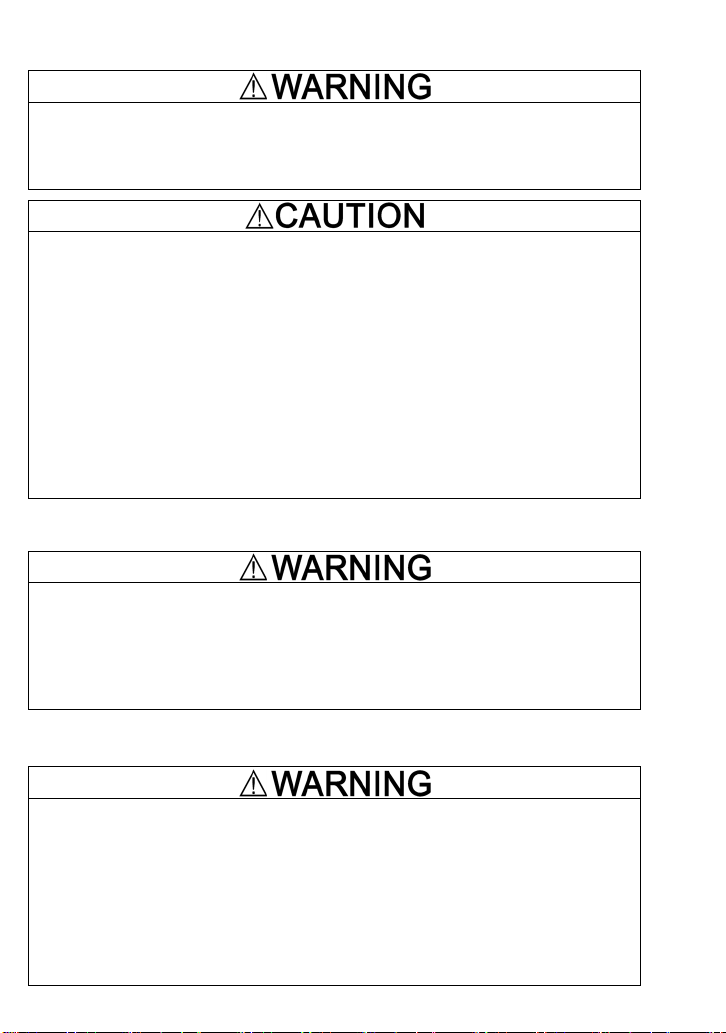
Installation and wiring
• Turn the inverter's power OFF and wait for at least five minutes before starting
installation and wiring.
• Qualified electricians should carry out wiring.
Otherwise, electric shock could occur.
• Do not use the products that are damaged or lacking parts.
Doing so could cause failure or injuries.
• Prevent lint, paper fibers, sawdust, dust, metallic chips, or other foreign materials from
getting into the inverter.
Otherwise, a fire or an accident might result.
• Incorrect handling in installation/removal jobs could cause a failure.
A failure might result.
• Noise may be emitted from the inverter, motor and wires. Implement appropriate
measure to prevent the nearby sensors and devices from malfunctioning due to such
noise.
Otherwise, an accident could occur.
Operation
• Be sure to mount the terminal cover before turning the power ON.
Do not remove the cover while the power is on.
Doing so could cause electric shock.
• Confirm and adjust the setting of the function codes before running the inverter.
Otherwise, an accident could occur.
Maintenance and inspection, and parts replacement
• Turn the inverter's power OFF and wait for at least five minutes before starting
inspection or parts replacement.
Otherwise, electric shock could occur
• Maintenance, inspection, and parts replacement should be made only by qualified
persons.
• Take off the watch, rings and other metallic objects before starting work.
• Use insulated tools.
Otherwise, electric shock or injuries could occur.
ii
Page 5

Disposal
• Treat the product as an industrial waste when disposing of it.
Otherwise injuries could occur.
Others
• Never attempt to modify the product.
Doing so could cause electric shock or injuries.
Icons
The following icons are used throughout this manual.
This icon indicates information which, if not heeded, can result in the inverter not
operating to full efficiency, as well as information concerning incorrect operations and
settings which can result in accidents.
This icon indicates information that can prove handy when performing certain settings
or operations.
This icon indicates a reference to more detailed information.
iii
Page 6

Table of Content
Preface ..............................................................................................................................i
Safety precautions .........................................................................................................i
Chapter 1 BEFORE USING THE INVERTER............................................................ 1-1
1.1 Acceptance Inspection ..................................................................................... 1-1
1.2 Mounting the Synchronous Operation Card..................................................... 1-2
1.3 Pulse Generator (PG) Specifications and PG1-Mounting Instructions............. 1-3
1.3.1 PG specifications ....................................................................................... 1-3
1.3.2 Connection between the synchronous operation card and PGs
on reference and slave motors .................................................................. 1-4
1.3.3 Wiring procedure for the PGs and the synchronous operation card ......... 1-5
1.3.4 Setting up the power supply for PGs......................................................... 1-6
1.3.5 Option terminals on the synchronous operation card................................ 1-6
1.3.6 Arrangement of option terminals on the synchronous operation card....... 1-6
Chapter 2 CONNECTION DIAGRAMS...................................................................... 2-1
Chapter 3 PREPARATION FOR OPERATING........................................................... 3-1
Chapter 4 SYNCHRONOUS OPERATION CONTROL ............................................. 4-1
4.1 Specifications of Synchronous Operation ........................................................ 4-1
4.2 Overview of Synchronous Operation ............................................................... 4-2
4.2.1 Standby synchronous operation ................................................................ 4-2
4.2.2 Simultaneous start synchronous operation................................................ 4-3
4.3 Block Diagrams ................................................................................................ 4-4
4.4 List of Function Codes ..................................................................................... 4-6
4.5 Unavailable Function Codes ............................................................................ 4-8
4.6 Configuring Function Codes............................................................................. 4-8
4.6.1 Motor constant data ................................................................................... 4-8
4.6.2 Data setting for synchronous operation ..................................................... 4-8
Chapter 5 CONFIGURATION EXAMPLES AND ADJUSTMENT GUIDE .................. 5-1
5.1 Typical Configuration and Pulse Setting .......................................................... 5-1
5.1.1 Speed reduction ratio setting ..................................................................... 5-1
5.1.2 Wiring of PGs............................................................................................. 5-3
5.2 Key Points on Function Code Configuration and Adjustment Guide................ 5-4
5.3 Function Code Configuration Examples........................................................... 5-6
5.3.1 For position synchronous operation (o60 = 1 or 2), #1.............................. 5-6
5.3.2 For position synchronous operation (o60 = 1 or 2), #2.............................. 5-7
5.3.3 For speed synchronous operation (o60 = 0).............................................. 5-8
5.4 Checking PG Pulse Rate ................................................................................. 5-9
Chapter 6 PROTECTIVE FUNCTIONS ..................................................................... 6-1
6.1 Overspeed Alarm (OS) .................................................................................... 6-1
6.2 Excessive Speed Deviation Alarm (ErE) ......................................................... 6-2
6.2.1 Function codes .......................................................................................... 6-2
6.2.2 Excessive speed deviation detection......................................................... 6-2
6.3 Excessive Deviation Alarm (Ero)..................................................................... 6-3
6.3.1 Function codes .......................................................................................... 6-3
iv
Page 7
Chapter 1 BEFORE USING THE INVERTER
1.1 Acceptance Inspection
Unpack the package and check the following:
(1) The synchronous operation card is the model you ordered.
(2) The card is not damaged during transportation--no defective parts or lacking parts.
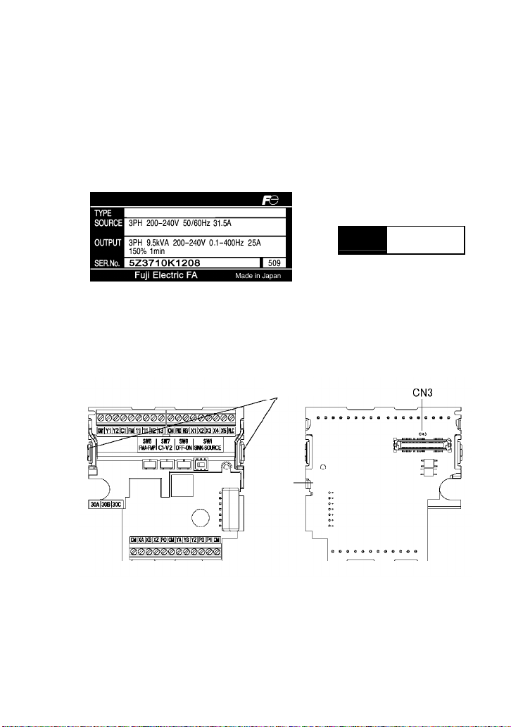
(3) The model name "OPC-E1-SY" is printed on the card. (See Figure 1.3.)
(4) The card is applicable to your inverter.
Applicable inverters have "-2SYZ," "-4SYZ," or "-7SYZ" at the end of the inverter type printed
in the TYPE column on the main and sub nameplates labeled on inverters.
FRN5.5E1S-2SYZ
TYPE
SER.No.
FRN5.5E1S-2SYZ
5Z3710K1208
Hooks
Model
name
OPC-E1-SY
(a) Main nameplate (b) Sub nameplate
Figure 1.1 Nameplates
If you suspect the product is not working properly or if you have any questions about your product,
contact your Fuji Electric representative.
Figure 1.2 Figure 1.3
1-1
Page 8
1.2 Mounting the Synchronous Operation Card
• Turn the power OFF and wait for at least five minutes before starting installation.
Otherwise, electric shock could occur.
• Do not use the product that is damaged or lacking parts.
Doing so could cause a failure and injuries.
• Prevent lint, paper fibers, sawdust, dust, metallic chips, or other foreign materials from
getting into the inverter.
Otherwise, a fire or an accident might result.
• Incorrect handling when mounting or removing the product could cause a failure.
A failure might result.
When handling the synchronous operation card and interface printed circuit board (interface PCB),
take any antistatic measure or hold their hooks taking care not to directly touch their circuit boards;
otherwise, the static electricity charged in your body may damage them.
(1) Remove the terminal cover.
For details on how to remove the terminal cover, refer to the FRENIC-Multi Instruction
Manual (INR-SI47-1094-E), Chapter 2, Section 2.3 "Wiring."
(2) If the interface PCB is mounted on the inverter, push the hooks provided on both ends of the
interface PCB and pull it up and out of the inverter with both hands. (Store the removed
interface PCB for future use.)
(3) Connect the CN3 connector (shown in Figure 1.3) on the synchronous operation card to the
connector on the inverter until it clicks into place.
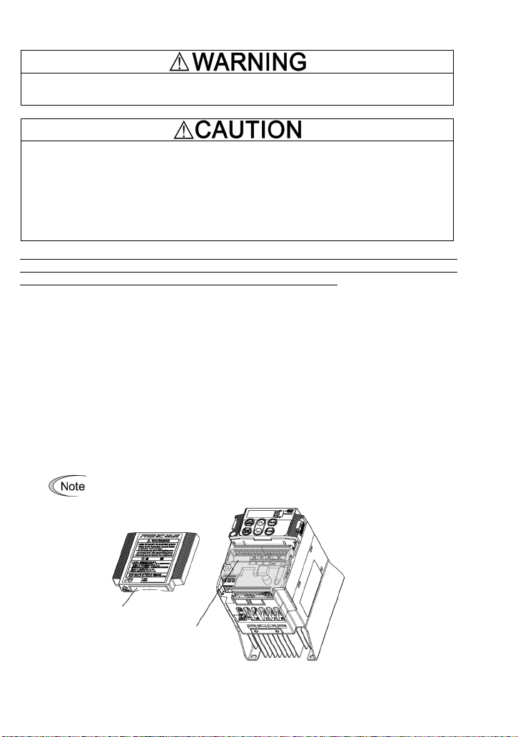
(4) For inverters of 0.75 kW or below: Before reinstalling the terminal cover, cut off the barrier (see
Figure 1.4) of the terminal cover using nippers or the like.
(5) Reinstall the terminal cover, taking care not to pinch control signal lines.
When reinstalling the terminal cover, refer to the FRENIC-Multi Instruction Manual
(INR-SI47-1094-E), Chapter 2, Section 2.3 "Wiring."
For inverters of 3.7 kW or below: When performing the wiring for the main
circuit terminals, you need to remove the synchronous operation card
beforehand.
Barrier of the cable outlet
Synchronous operation card
Figure 1.4
1-2
Page 9
1.3 Pulse Generator (PG) Specifications and PG Mounting Instructions
• Using the pulse generator (PG) whose specifications are not satisfied may cause the
inverter and equipment to malfunction.
Doing so could cause failure or injuries.
1.3.1 PG specifications
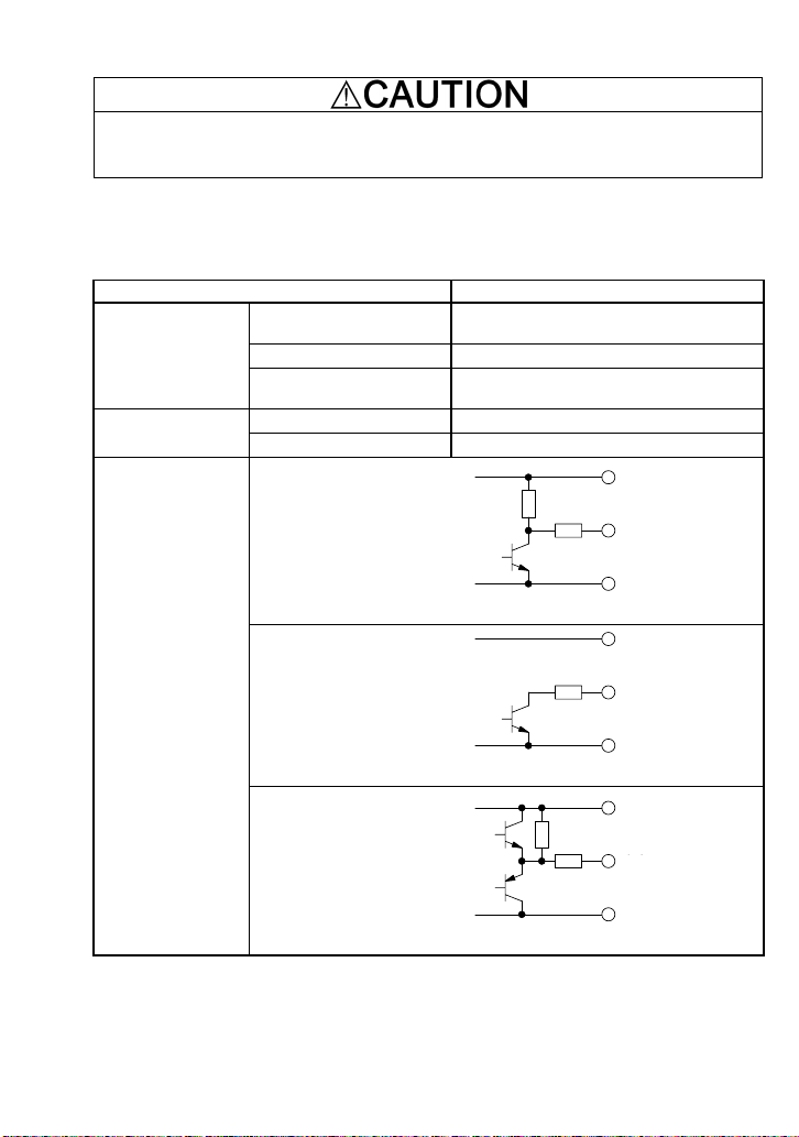
Table 1.1 lists the specifications of PGs applicable to the synchronous operation card.
Table 1.1 Specifications of Applicable PG and Synchronous Operation Card
Item Specifications
A and B phases (Incremental system),
Z phase
20 to 3000 P/R
5 VDC ±10% / 100 mA
(200 mA, when a single PG is mounted.)
+5 VDC ±10% / 200 mA
+5 VDC ±10%, 200 mA or more
Vcc
Applicable PG
PG power supply
Encoder system
Pulse resolution
Input power requirements
Internal power supply
External power supply
Voltage output
Circuit configured with the
grounded-emitter
Output
出力
transistor whose collector
outputs voltage
Open collector
0V
Vcc
(pull-up resistor: 620Ω)
Output signal type
Voltage output circuit
出力
Output
configured without resistor
between the output
terminal and the collector
Complementary
0V
Vcc
(totem-pole push-pull)
Constant voltage output
出力
Output
circuit configured with an
emitter follower
0V
Note 1: The wiring length between the PG and inverter should not exceed 20 m.
Note 2: When the PG power is 200 mA or more, use an external power supply.
Note 3: The external power supply should satisfy the voltage specifications of the PG.
Note 4: The reference and slave motors should use pulse generators with the same pulse
resolution.
1-3
Page 10
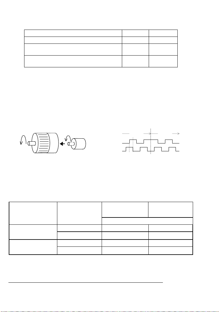
Select PGs that match the DC characteristics of the synchronous operation card listed in the table
below.
Table 1.2 DC Characteristics of the Synchronous Operation Card
Terminals XA, XB, XZ, YA, YB, YZ Min. Max.
High level input voltage VIH 3.8 V --
Low level input voltage VIL
(Input current 9 mA or less)
Low level input current IIL
(when an internal power supply is used, VIL=0V)
-- 1.2 V
-- 9 mA
1.3.2 Connection between the synchronous operation card and PGs on reference and slave motors
Connect the PG output signal wires for the reference motor to terminals XA, XB, and XZ on the
synchronous operation card and those for the slave motor, to terminals YA, YB, and YZ.
The counterclockwise rotation when viewed from the motor output shaft is regarded as "forward
rotation" (see Figure 1.5). The PG output signal wires should be connected so that the PG output
pulse during rotation in the forward direction forms the forward signal as shown in Figure 1.6 (B
phase advances 90 degrees from A phase).
Forward direction
A phase input
B phase input
Motor
Figure 1.5 Forward Direction of Motor and PG Figure 1.6 Rotational Direction and Output Signal
Table 1.3 lists the relationship between the connection of reference PG output signals, the
rotational direction of the reference PG, and the rotational direction of the slave motor that receives
PG
of PG
90°
Forward
signal
Reverse
signal
a run command (FWD or REV).
Table 1.3 Connection of the Reference PG Output Signals and Rotational Direction of the Slave Motor
A and B phase output
signals issued from the
reference PG
If connected to
terminals XA and XB
normally
If connected to
terminals XA and XB
reversely
* If the reference inverter rotates the motor in such a direction that the slave inverter stops, the
pulse count continues so as to cause an Ero excessive deviation alarm. After that, if the
reference inverter rotates the motor in the same direction as the slave inverter, the synchronous
operation restarts from the position where the deviation becomes zero.
When the rotational
direction of the
reference PG is:
Forward Forward Stop *
Reverse Stop * Reverse
Forward Stop * Reverse
Reverse Forward Stop *
If the slave motor
receives a run forward
command (FWD):
It rotates in the following direction.
Note: Synchronous operation in the direction opposite to the reference PG rotation
If the slave motor
receives a run reverse
command (REV):
To drive the slave PG in the direction opposite to the reference PG rotation in synchronous
operation, connect the B and A phase output signals issued from the reference PG to terminals XA
and XB, respectively. (See Table 1.3.)
1-4
Page 11
1.3.3 Wiring procedure for the PGs and the synchronous operation card
• Turn the inverter's power OFF and wait for at least five minutes before starting
connection.
• Qualified electricians should carry out wiring.
Otherwise, electric shock could occur.
• Noise may be emitted from the inverter, motor and wires. Implement appropriate
measure to prevent the nearby sensors and devices from malfunctioning due to such
noise.
Otherwise, an accident could occur.
Wire each PG to the synchronous operation card, observing the following precautions and referring
to the connection diagrams given in Figures 2.1 and 2.2.
(1) Turn the inverter's power OFF.
(2) Use a shielded wire for wiring between the PG and the synchronous operation card.
(3) To prevent malfunction due to noise, keep the wiring away from the main circuit wiring of the
inverter and the power wiring of other devices as far as possible (at least 10 cm). Do not route
them in the same duct.
(4) Complete the wiring for the PG before turning the inverter's power ON.
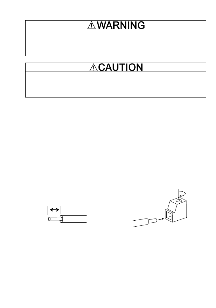
(5) The wire size applicable to the option connection terminal on the inverter is AWG 18-24.
When using a wire with its end being stripped, strip its end by 5 to 7 mm. When using a ferrule,
use a vinyl-insulated ferrule.
Loosen the fixing screw, insert the wire end into the opening of the terminal block, and tighten
the screw.
5 to 7 (mm)
Figure 1.7 Stripping the Wire End Before Connection to Terminal Block
Recommended wire: AWG 18-24 for rated temperature 105°C (UL)
1-5
Page 12
1.3.4 Setting up the power supply for PGs
When using an internal power supply
Connect the power supply wire to terminal [PO] on the synchronous operation card.
When using an external power supply
Connect the power supply wire to terminal [PI] on the synchronous operation card.
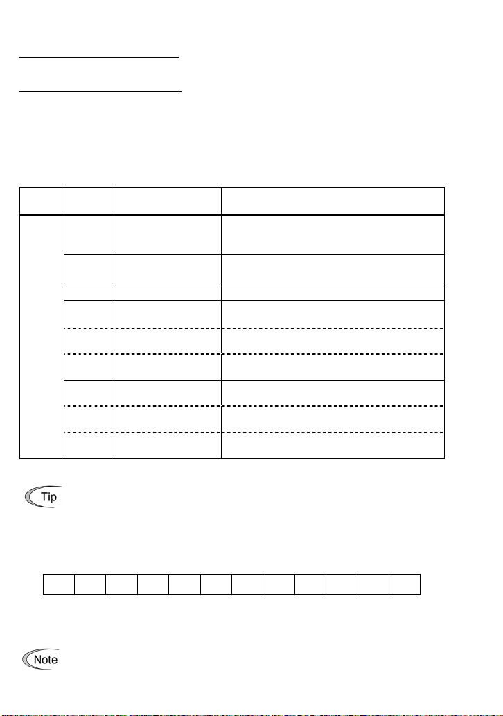
1.3.5 Option terminals on the synchronous operation card
Table 1.4 lists terminal symbols, names and functions of the option terminals on the synchronous
operation card.
Table 1.4 Option Terminals and Their Specifications
Classification
Note: Incorrect wiring of A/B phase could fail to run the motor normally or cause an inverter trip.
Terminal
symbol
External power supply
PI
input
PO Power supply for PG
CM PG common
XA A phase pulse input X
XB B phase pulse input X
PG/ Pulse input
XZ Z phase pulse input X
YA A phase pulse input Y
YB B phase pulse input Y
YZ Z phase pulse input Y
Name Functions
Power input terminal from the external device
External power supply capacity:
5 VDC ±10%, 200 mA or more
Power output terminal
5 VDC ±10%, Maximum output 200 mA
Common terminal for power supply and PG input
Input terminal for A phase signal issued from
reference PG
Input terminal for B phase signal issued from
reference PG
Input terminal for Z phase signal issued from
reference PG
Input terminal for A phase signal issued from
slave PG
Input terminal for B phase signal issued from
slave PG
Input terminal for Z phase signal issued from
slave PG
Input signal status (pulse rate) on terminals [XA], [XB], [XZ], [YA], [YB], and [YZ] can be
checked by using Menu #4 "I/O Checking" (4_15, 4_16, 4_17 and 4_18) on the
inverter's keypad. For the operating procedure, refer to the FRENIC-Multi Instruction
Manual (INR-SI47-1094-E). (Function code E52 = 2)
1.3.6 Arrangement of option terminals on the synchronous operation card
CM XA XB XZ PO CM YA YB YZ PO PI CM
Screw size: M2
Tightening torque: 0.22 to 0.25 N·m
Terminal [PLC] on the synchronous operation card cannot supply power to external
equipment. Use the terminal only for receiving power from external equipment.
Figure 1.8 Option Terminals
1-6
Page 13

Chapter 2 CONNECTION DIAGRAMS
Figure 2.1 shows connection diagram examples for synchronous operation.
Ⅰ.インバータ内部電源使用時
1. When using inverter internal power supply
Reference
FRN-E1S-SYZ
L1/R
L2/S
L3/T
G
OPC-E1-SY
U
V
W
PI
PO
YA
YB
YZ
CM
PO
XA
XB
XZ
CM
Slave
motor
追従側
M M
PG
motor
基準側
PG
Ⅱ.外部電源使用時
2. When using external power supply
FRN-E1S-SYZ
G
OPC-E1-SY
U
V
W
PI
PO
YA
YB
YZ
CM
PO
XA
XB
XZ
CM
5Vdc ±10%
L1/R
L2/S
L3/T
Slave
追従側
motor
M M
PG
Reference
基準側
motor
PG
Figure 2.1 Connection Diagrams for Synchronous Operation
In order to conform the inverter to the requirements of EMC Directive, ground the shields of the
PG cables to the inverter as shown below.
1. When using inverter internal power supply
Ⅰ.インバータ内部電源使用時
Reference
FRN-E1S-SYZ
L1/R
L2/S
L3/T
G
OPC-E1-SY
U
V
W
PI
PO
YA
YB
YZ
CM
PO
XA
XB
XZ
CM
Slave
motor
追従側
motor
M M
PG
基準側
PG
2. When using external power supply
Ⅱ.外部電源使用時
FRN-E1S-SYZ
L1/R
L2/S
L3/T
G
OPC-E1-SY
U
V
W
PI
PO
YA
YB
YZ
CM
PO
XA
XB
XZ
CM
Slave
motor
追従側
M M
PG
Reference
motor
基準側
PG
5Vdc ±10%
Figure 2.2 Connection Diagrams for Compliance with EMC Directive
Note: For details about applicable PGs, see Table 1.1 in Chapter 1, Section 1.3.1 "PG specifications."
2-1
Page 14

Chapter 3 PREPARATION FOR OPERATING
After completion of mounting and wiring but before turning the inverter's power ON, check the
followings.
(1) The wiring is correct.
(2) There is no cable waste or screws left.
(3) The screws and terminals are firmly tightened.
(4) The straggling wires at ferrules are not short-circuited to other terminals.
Furthermore, after powering the inverter ON but before starting inverter operation, check the
followings.
• Check the wiring surely before running the inverter. Incorrect wiring causes the inverter
or other devices to malfunction.
Failure to do so could cause failure or injuries.
• Be sure to mount the terminal cover before turning the power ON.
Do not remove any cover while the power is ON.
Doing so could cause electric shock.
• Confirm and adjust the configuration of the function codes before running the inverter.
Otherwise, an accident could occur.
3-1
Page 15

Chapter 4 SYNCHRONOUS OPERATION CONTROL
The synchronous operation control enables the slave inverter to detect the reference motor rotation
with PG signals and synchronize the slave motor with the reference motor in rotation speed and
position.
The synchronous operation is available in three modes--Speed synchronous (o60 = 0), standby
synchronous (o60 = 1), and simultaneous start synchronous (o60 = 2) operation.
Reference motor's PG signals should be input to terminals XA, XB, and XZ, and slave motor's ones,
to terminals YA, YB, and YZ.
4.1 Specifications of Synchronous Operation
Table 4.1 lists the specifications of the synchronous operation.
Table 4.1 Specifications of Synchronous Operation
Item Specifications Remarks
Control
Electrical
requirements
Speed control range 180 to 3600 r/min
Position control accuracy
Input pulse rate 75 p/s to 30 kp/s
For the procedure on how to calculate the PG input pulse rate based on the inverter
output frequency, refer to Section 5.4 "Checking PG Pulse Rate."
±5°
4-pole motors and PGs with 1000 P/R
Speed reduction ratio = 1:1
During running at constant speed
Maximum wiring length: 20 m
A/B phase encoders
4-1
Page 16

4.2 Overview of Synchronous Operation
4.2.1 Standby synchronous operation
In standby synchronous operation (o60 = 1), the inverter controls the slave motor to synchronize its
Z phase with the reference motor's Z phase, based on the first detected Z phases (positions) of those
two motors after the start of synchronous operation. The slave motor could cause a single cycle
delay at a maximum (on standby) at the start of operation.
Once the slave motor starts running after standby, it will never go standby unless the synchronous
operation is cancelled (see Note 1 below).
The Z phase synchronization angles of the reference and slave motors can be adjusted with the
function code o66.
The inverter integrates the position pulses for each of the reference and slave motors and controls
the slave motor's rotation speed and position to keep the difference between those two motors
(hereafter called deviation) at zero.
If any incorrect count due to electrical noise or other factors is found in the integrated count of A/B
phases, the inverter corrects the error based on the Z phase difference.
If the deviation between those two motors falls below the synchronization completion detection angle
(specified by o67), the SY synchronization completion signal will be issued. If synchronization is lost
so that the deviation exceeds 100 times the excessive deviation setting (specified by o68), the
inverter shuts down its output with the Ero alarm.
Reference PG
rotation speed
Run command
for slave motor
t
t
Slave PG
rotation speed
Reference PG
phase angle
Slave PG
phase angle
SY
Note 1: Synchronous operation cancellation conditions
The synchronous operation is canceled when:
- The run command for the slave motor is turned OFF,
- The protective function is activated, or
- The inverter switches to a single motor drive. (Assign terminal command Hz2/Hz1 and switch the
output
360°
0°
360°
0°
OFF ON
Synchronization completedStart of standby
Figure 4.1 Standby Synchronous Operation
frequency command source with F01/C30.)
4-2
t
t
t
t
Page 17

4.2.2 Simultaneous start synchronous operation
In simultaneous start synchronous operation (o60 = 2), the inverter controls the rotation speed and
position of the slave motor to maintain the phase difference between the reference and slave motors
at the time when the single motor drive operation is switched to the synchronous operation. That is,
it keeps the deviation between the integrated position pulses of the reference and slave motors at
zero.
If the deviation falls below the synchronization completion detection angle (specified by o67), the SY
synchronization completion signal will be issued. If synchronization is lost so that the deviation
exceeds 100 times the excessive deviation setting (specified by o68), the inverter shuts down its
output with the Ero alarm.
If any incorrect count due to electrical noise or other factors is found in the integrated count of A/B
phases, the inverter corrects the error based on the Z phase difference.
If the run command for the slave motor is turned OFF, the inverter continues to monitor the motor
positions as long as the synchronous operation is not switched to the single motor drive operation.
When the run command is turned ON again, the inverter restarts to control the slave motor to
maintain the Z phase difference between the reference and slave motors.
Reference PG
rotation speed
Run command
for slave motor
Slave PG
rotation speed
Reference motor
integrated pulses
Slave motor
integrated pulses
0
0°
0
0°
Excessive deviation detected
t
t
t
Deviation of
position
SY
output
Reference PG
phase angle
Slave PG
phase angle
OFF
360゜
0゜
360゜
0゜
ON
Correct the integrated values so that the Z phase
difference becomes the same as the first applied one.
Slave PG
Z phase
Reference
PG Z phase
Figure 4.2 Simultaneous Start Synchronous Operation
4-3
t
t
t
t
Page 18

4.3 Block Diagrams
Output
frequency
[F42]
/[A14]
Frequency command
+
+
+
+
[o13]
Slip
frequency
calculation
V/f control without PG (F42/A14=0)
processor
decelerator
Accelerator/
(*2)
[F15]
[F07][F08]
[F16]
V/f control without PG (F42/A14=1, 2)
[E10][E11]
(*3)
Slip
frequency
calculation
[o02] [o03]
-
+
[o04]
ErE
speed
Excessive
V/f speed control with PG (F42/A14=3, 4)
output
The frequency limiter (Low) limits the referenc e frequency.
The frequency limiter (High) limits th e reference frequency.
input terminals switches between frequency command 1 (F01) and
frequency command 2 (C30). It can be used for switching between
synchronous operation and single motor drive operation .
Using the terminal command Hz2/Hz1 assigned to one of the digital
[o18]
(*1)
(*2)
deviation
detection
[o17]
(*3)
(*1)
Hz2/Hz1
Terminal command
[o06][o05]
[o08]
by F01 or C30
Speed
[P01]/[A15]
converter
[o07]
[P01]/[A15]
[o10]
[o012]
Speed
[o011]
converter
[o09]
input
Hardware Software
Reference
PG A/B
input
Reference
phase input
PG Z phase
Slave PG
A/B phase
input
Z phase
Slave PG
Figure 4.3 Block Diagram for Speed Synchronous Operation (o60 = 0)
4-4
Page 19

Output
frequency
[F42]
/[A14]
+
+
+
+
[o13]
Slip
frequency
calculation
V/f control without PG (F42/A14=0)
processor
decelerator
Accelerator/
(*2)
[F15]
(*3)
[F16]
Main speed
by F01 or C30
Frequency command
(*2)
[F15]
+
+
[o63],[o64]
Limiter
regulator
[o61]=1.0
+
APR
[o06]
Speed
converter
[o07]
+
Position
deviation
[o05] [o08]
[P01]/[A15]
+
-
[F07][F08]
[E10][E11]
[o62]
[o12]
[o11]
V/f control without PG (F42/A14=1,2)
Hz2/Hz1 (*1)
Terminal command
SY signal
completion
Synchronization
Slip
frequency
calculation
[o02] [o03]
-
+
[o04]
output
Ero output
[o68]
deviation
detection
[o67]
Excessive
detection
[P01]/[A15]
Speed
+
angle
+
Offset
converter
[o66]
ErE
output
[o18]
speed
V/f speed control with PG (F42/A14=3,4)
deviation
detection
Excessive
[o10][o09]
[o12]
[o11]
[o17]
Using the terminal command Hz2/Hz1 assigned to
one of the digital input terminals switches between
frequency command 1 (F01) and frequency command
2 (C30). It can be used for switching between
synchronous operation and single motor drive
operation.
The frequency limiter (Low) limits the reference frequency.
The frequency limiter (High) limits the r eference frequency.
(*1)
(*3)
(*2)
[o65]
[o12]
[o11]
according to Z phase
Frequency compensator
(encoder position deviation)
[o09]
Accumulator
input
phase
Hardware Software
PG A/B
Reference
Reference
PG Z phase
input
Accumulator
input
Slave PG
A/B phase
input
Z phase
Slave PG
Figure 4.4 Block diagram for Position Synchronous Operation (o60 = 1, 2)
4-5
Page 20

4.4 List of Function Codes
Table 4.2 lists function codes related to synchronous operation control.
Table 4.2 Function Codes
Change
Code Name Data setting range Unit
F01
Frequency Command 1
(C30)
(Frequency Command 1)
F42
Control Mode
(A14)
Selection
E01
E02
Terminal [X1], [X2], [X3],
E03
[X4], [X5] function
E04
E05
Terminal [FWD], [REV]
E98
function
E99
E20,
Terminal [Y1],
E21,
[Y2], [30A/B/C]
E27
Reference/
o01
Slave PG Input
o02 Speed Control (P Gain) 0.01 to 200.00 -- 10.00 Y
o03 (Integral time) 0.000 to 5.000 s 0.100 Y
o04 (Filter time constant) 0.000 to 5.000 s 0.020 Y
Reference PG
o05
Pulse
o06 (Filter time constant) 0.000 to 5.000 s 0.005 Y
o07
o08
Slave PG
o09
Pulse
o10 (Filter time constant) 0.000 to 5.000 s 0.005 Y
o11 (Pulse count factor 1) 1 to 9999 -- 1 N
o12 (Pulse count factor 2) 1 to 9999 -- 1 N
o13 Speed Control (Output limiter) 0.00 to 100.00 % 100.00 Y
Speed
o17
Deviation
o18 (Excessive deviation timer) 0.0 to 10.0 s 1.5 Y
*1 For position synchronization (o60 = 1 or 2), use pulse generators with the same pulse resolution at both
the reference and slave motors.
(Encoder pulse resolution)*10: Same as o09
(Encoder pulse resolution)
(Excessive deviation level)
(Function)
(Function)
(Input mode) 2: A/B phase pulse -- 2 N
(Pulse count factor 1)
(Pulse count factor 2)
0 to 3, 5, 7, 11, 12
(Set F01 or C30 to
12.)
0 to 4
(Set F42 or A14 to
3 or 4 for selecting
speed control
with optional PG
interface.)
11 (1011): Hz2/Hz1
Select frequency
command 2/1
(Only the related
items indicated)
29 (1029): SY
Synchronization
completed
(Only the related
items indicated)
20 to 3600
0: Same as o11
1 to 9999
0: Same as o12
1 to 9999
20 to 3600 P/R 1024 N
*1
0 to 50 % 20 Y
Default
setting
--
--
-- -- N
-- -- N
P/R 0 N
-- 0 N
-- 0 N
(2)
(0)
when
running
0
0
N
N
4-6
Page 21

Code Name Data setting range Unit
PG Error
Processing
ErE
o19
Synchronous
Operation
o60
(Main speed
o61
o62 (APR P gain) 0.00 to 200.00 -- 15.00 Y
(APR positive output
o63
(APR negative output
o64
(Z phase alignment
o65
(Synchronous offset
o66
(Synchronization
o67
(Excessive deviation
o68
For function codes not listed above, see the FRENIC-Multi Instruction Manual (INR-SI47-1094-E),
Chapter 5, "Function Codes." For codes that are listed above and also in the FRENIC-Multi
Instruction Manual, descriptions in this manual precede.
Table 4.2 Function Codes (Continued)
0: Continue to run
(Detection cancel)
1: Stop running
(Alarm mode 1)
2: Stop running
(Alarm mode 2)
0: Speed synchronous
operation
(Mode selection)
regulator gain)
completion detection
detection range)
1: Position synchronous
operation (Standby)
2: Position synchronous
operation
(Simultaneous start)
Fixed to 1.0 -- 1.0 Y
20 to 200,
limiter)
999: Without limiter
20 to 200,
limiter)
999: Without limiter
0.0 to 10.0 -- 1.0 Y
gain)
0 to 359 deg 0 Y
angle)
0 to 100 deg 15 Y
angle)
0.0 to 6553.5 -- 6553.5 Y
Change
Default
setting
-- 2 N
-- 0 N
% 999 Y
% 999 Y
when
running
4-7
Page 22

4.5 Unavailable Function Codes
The following function codes are not available.
H70 Overload Prevention Control
J01 PID Control (Mode selection)
J65 Overload Stop (Mode selection)
J73 to J88 Position Control
4.6 Configuring Function Codes
To enable synchronous operation, be sure to select the speed control with optional PG interface
(F42/A14 = 3, 4). Other function codes should be configured as described below.
When configuring the function codes, refer to Chapter 5 "FUNCTION CODE CONFIGURATION
EXAMPLES AND ADJUSTMENT GUIDE."
4.6.1 Motor constant data
Configure function codes F03 to F05, P01 to P03, P06 to P12 and P99, referring to the FRENIC-Multi
Instruction Manual (INR-SI47-1094-E), Chapter 5 "Function Codes."
When using motor 2, configure A01 to A03, A15 to A17, A20 to A26, and A39.
4.6.2 Data setting for synchronous operation
F01 Frequency Command 1
C30 Frequency Command 2
Select the pulse train input (F01/C30 = 12) as a reference command source.
Switching between synchronous operation and single motor operation is possible using the
Hz2/Hz1 terminal command (see Figure 4.4). The switching example is given below.
(Example) Turning terminal [X1] ON for single motor operation during which a digital
frequency command drives the inverter
Set F01 and C30 data to "12" and "0," respectively. And set E01 data to "11" to assign the
Hz2/Hz1 command to terminal [X1].
It is recommended to perform switching between synchronous operation and single motor
operation when the inverter is stopped. Switching when the inverter is running may activate
the protective function. To avoid it, decrease the difference between the output frequency and
the reference frequency after switching.
4-8
Page 23

F07 Acceleration Time 1
F08 Deceleration Time 1
E10 Acceleration Time 2
E11 Deceleration Time 2
Also in synchronous operation, the inverter controls the output frequency according to the
acceleration/deceleration time as usual. Specify the acceleration/deceleration time as short
as possible. Be careful that, if the acceleration/deceleration time longer than that of the
reference inverter is specified, the following capability of the slave motor will be lost.
F42 Control Mode Selection 1
A14 Control Mode Selection 2
For synchronous operation, set the F42 (A14) data to "3" or "4" to select the V/f control with
optional PG interface or dynamic torque vector control with optional PG interface,
respectively.
o01 Reference/Slave PG Input (Input mode)
For synchronous operation, the o01 data is fixed to "2: A/B phase pulse."
o02 Speed Control (P Gain)
o03 Speed Control (Integral time)
These function codes specify the PI constants of the slave motor's speed controller. The
expression below shows the transfer function of the regulator.
(1kf
PS
Kp : P gain (o02)
: Integral time (o03)
T
I
* : Slip frequency
f
S
ε : Speed deviation
s : Laplace operator
Suppose that the P gain is 1.0 when the speed deviation ε = 100% (Maximum Frequency F03
(A01)) and f
is 1% of the maximum frequency.
S
Suppose that the I integral time = 1.000 seconds when the o03 data is 1.000.
Setting an excessive P gain may cause system hunting. A roughly recommended P gain
should not exceed 35.00 in the ordinary system.
Modifying F03 (A01) data requires readjustment of o02 and o03 data.
1
ε)
×+=*
sT
I
4-9
Page 24

o04 Speed Control (Filter time constant)
This function code specifies a time constant determining a linear delay of the low pass filter for
the speed command given by pulse train. Use this function code to suppress an overshoot
that occurs, for example, when the speed command varies.
o05 Reference PG Pulse (Encoder pulse resolution)
o09 Slave PG Pulse (Encoder pulse resolution)
Set the encoder pulse resolution of the reference motor to o05, and that of the slave motor
(driven by the inverter) to o09. For position synchronization (o60 = 1 or 2), be sure to use PGs
with the same encoder pulse resolution for both the reference and slave motors. When o05 =
0, the inverter recognizes that o05 = o09 and operates accordingly.
o06 Reference PG Pulse (Filter time constant)
o10 Slave PG Pulse (Filter time constant)
o06 and o10 specify time constants determining a linear delay of the low pass filter for the
speed feedbacks given by reference and slave PGs, respectively. Use these function codes,
for example, when the large ripple components superpose the feedback pulse train.
o07 Reference PG Pulse (Pulse count factor 1)
o08 Reference PG Pulse (Pulse count factor 2)
o11
o12
Slave PG Pulse (Pulse count factor 1)
Slave PG Pulse (Pulse count factor 2)
If the slave motor has reduction gears etc., specify the slave PG pulse count factors 1 and 2.
Pulley
(Transmission ratio c /d )
Radius: d
YA,YB,YZ
Power
supply
L1/R,L2/S,L3/T
Conveyer
PG
Radius: c
Inverte r
FRN-E1S-SYZ
(Transmission ratio
No. of
teeth: b
Motor
No. of
teeth: a
Gear train
a/b)
No. of
teeth: a
U,V,W
Figure 4.5 Speed Control Model Using a PG
Slave motor shaft speed =
Pulse count factor 2 (o12)
Pulse count factor 1 (o11)
Pulse count factor 2 (o12) b d
Pulse count factor 1 (o11)
× Encoder shaft speed
=
a
×
c
For synchronous operation, it is recommended that the reduction ratios (pulse count factors)
of the reference and slave sides be identical. To make them identical, set both o07 and o08
data to "0," applying the pulse count of the slave PG to that of the reference PG. If the
reduction ratios are different between the two, refer to Section 5.1 "Typical Configuration and
Pulse Setting."
4-10
Page 25

o13 Speed Control (Output limiter)
This function code specifies the output limit percentage for the speed controller (PI controller).
Specification of 100.00% is equivalent to the maximum speed (maximum frequency).
To suppress the frequency control amount (PI controller output) to the extent of the motor's
slip frequency in the speed control mode, use this function.
o60 Synchronous Operation (Mode selection)
This function code specifies the synchronous operation mode.
Table 4.3 Data for Function Code o60
Data for o60 Synchronous Operation Mode Synchronization system Z phase signal
0 Speed synchronous operation Speed synchronization Not required.
1 Standby synchronous operation
2
Simultaneous start synchronous
operation
Position synchronization Required.
o61 Synchronous Operation (Main speed controller gain)
This function code is fixed at 1.0 and cannot be changed.
o62 Synchronous Operation (APR P gain)
This function code determines the response of the automatic position regulator (APR). (See
Figure 4.4.)
If the APR output reaches the maximum frequency when the phase angle deviation (position
deviation) between the reference and slave PGs becomes equal to the pulse rate at the
maximum frequency, that gain is assumed to be 1.0.
Setting a too large value to the gain data easily causes hunting, and setting a too small value
results in a large steady-state deviation.
o63 Synchronous Operation (APR positive output limiter)
o64 Synchronous Operation (APR negative output limiter)
These function codes specify the limits of APR output relative to the reference motor speed.
(See Figures 4.4 and 4.6.)
Specification of "999" disables the limiter.
Reference
motor speed
Position
deviation
o61
o63
APR
o62
+
+
ASR
o64
Figure 4.6 Operation of APR Output Limiter
4-11
Page 26

S
o65 Synchronous Operation (Z phase alignment gain)
Specify a large value to this function code data when the steady-state deviation is large.
If the APR output reaches the maximum frequency when the phase angle deviation between
the reference and slave PGs (position deviation) becomes 10% of the pulse rate at the
maximum frequency, that gain is assumed to be 1.0.
o66 Synchronous Operation (Synchronous offset angle)
In standby synchronous operation, the slave inverter delays starting to synchronize the Z
phase of the slave motor with that of the reference motor by the offset angle specified by this
function code.
o67 Synchronous Operation (Synchronization completion detection angle)
This function code specifies the synchronization completion detection angle.
If the absolute value of the phase angle deviation (position deviation) between the reference
and slave PGs becomes equal to or below the synchronization completion detection angle
specified by o67, the inverter issues a synchronization completion signal SY, provided that
the E20, E21, or E27 data (Terminal function) is set to "29" (Synchronization completed).
Once turned ON, the synchronization completion signal SY is kept ON for 100 ms.
Synchronization
completion
detection signal
ON
OFF
Y
-o67 o67
0°
Position deviation
Figure 4.7 Synchronization Completion Detection Signal SY
o68 Synchronous Operation (Excessive deviation detection range)
This function code specifies the detection range for excessive deviation alarm (Ero). If the
absolute value of the phase angle deviation (position deviation) between the reference and
slave PGs exceeds 100 times the o68 setting, the inverter issues an alarm Ero and shuts
down its output.
Excessive
deviation alarm
Ero
-o68×100 o68×100
ON
OFF
0°
Position deviation
Figure 4.8 Excessive Deviation Alarm Ero
4-12
Page 27

Chapter 5 CONFIGURATION EXAMPLES AND ADJUSTMENT GUIDE
5.1 Typical Configuration and Pulse Setting
5.1.1 Speed reduction ratio setting
Figure 5.1 shows the system configuration applicable to the synchronous operation, taking a
conveyer system as an example.
Table 5.1 lists the availability of position synchronous operation and the setting values for pulse
count factors 1/2 depending on the speed reduction ratio of each reduction gear when the position
synchronous operation is enabled (o60 = 1, 2). Table 5.2 shows the settings for the speed
synchronous operation (o60 = 0).
Reference conveyer Slave conveyer
Speed reduction ratio Sm
Slave
motor
Speed reduction
Cm
ratio
Power
supply
R, S, T
Reference
motor
FRN-E1S
U, V, W
Speed reduction
ratio Cp
Reference
PG
YA, YB, YZXA, XB, XZ
Figure 5.1 Configuration Example of Conveyer Synchronization System
Table 5.1 Availability of Position Synchronous Operation (o60 = 1 or 2) and Settings
Speed reduction ratio
conditions
Motor
reduction
gear
PG
reduction
gear
Cm = Sm Cp = Sp
Cm ≠ Sm Cp = Sp
Cm = Sm Cp ≠ Sp
Cm x Cp = Sm x Sp
Cm ≠ Sm Cp ≠ Sp
Speed/position synchronization
of conveyer belts
Available Available
Available Available
Not available
speed conveyer Reference
- In position synchronous operation, be sure to use pulse generators with the same pulse resolution at
both the reference and slave sides. The pulse resolution should be set to o09. Set the o05 data to "0."
The equations in the above table are for cases where the reference and slave motors have the same
number of poles.
- For configuration examples, refer to Sections 5.3.1 and 5.3.2.
speed conveyer Slave
Speed reduction ratio Sp
Slave PG
Sp
=
Cp
FRN-E1S-SYZ
+
OPC-E1-SY
Speed/position
synchronization
of
PG shafts
Available
Available
Available
Pulse count
factor
0o07
=
0o08
=
o12
=
o11
U, V, W
1
SpSm
×
5-1
Page 28

Table 5.2 Settings for Speed Synchronous Operation (o60=0)
Settings at
reference side
For reference PG o05
For slave PG o09
- Speed synchronous operation is possible even if the number of poles of the reference motor is different
from that of the slave motor.
Set the number of poles of the slave motor to P01/A15.
- For the configuration example, refer to Section 5.3.3.
PG pulse
resolution
Pulse count factor
1
o08
=
o07
o12
o11
CpSm
×
1
=
SpSm
×
Remarks
When the pulse resolution of the reference
PG is identical with that of the slave PG
(specified by o09), set the o05 data to "0" so
that the inverter recognizes that o05 = o09
and operates accordingly.
If the pulse count factors of the reference PG
are identical with those of the slave PG, set
both o07 and o08 data to "0" so that the
inverter recognizes that o07 = o11 and o08 =
o12 and operates accordingly.
--
5-2
Page 29

5.1.2 Wiring of PGs
Table 5.3 shows three wiring patterns of reference and slave PGs according to the rotational
directions of those PGs in relation to that of the slave motor.
Table 5.3 System Configuration and Wiring of PGs
System configuration examples Wiring of PGs
Reference conveyer Slave conveyer
Reference
Slave PG
Power
supply
XA, XB, XZ
R, S, T
PG
YA,YB,YZ
FRN-E1S-SYZ
+
OPC-E1-SY
Slave motor
ForwardForwardForward
U, V, W
Reference PG
Î Normal connection to
terminals XA and XB
Slave PG
Î Normal connection to
terminals YA and YB
Reference conveyer Slave conveyer
Reverse
Reference PG
Power
XA, XB, XZ
supply
R, S, T
Reference conveyer Slave conveyer
Forward
Power
supply
Reference
R, S, T
YA,YB,YZ
PG
Slave PG
Slave PG
YA,YB,YZXA, XB, XZ
Forward
Reverse
FRN-E1S-SYZ
+
OPC-E1-SY
FRN-E1S-SYZ
+
OPC-E1-SY
5-3
Forward
Forward
Slave motor
U, V, W
Slave motor
U, V, W
Reference PG
Î Reverse connection
to terminals XA and
XB
Slave PG
Î Normal connection to
terminals YA and YB
Reference PG
Î Normal connection to
terminals XA and XB
Slave PG
Î Reverse connection
to terminals YA and
YB
Page 30

5.2 Key Points on Function Code Configuration and Adjustment Guide
In a trial run of your system, check the following function codes and use their settings as an
adjustment guide.
o05
Reference pulse (Encoder pulse resolution)
o07 (Pulse count factor 1)
o08 (Pulse count factor 2)
o09 Slave pulse (Encoder pulse resolution)
o11 (Pulse count factor 1)
o12 (Pulse count factor 2)
P01/A15 Motor (No. of poles)
In synchronous operation, it is necessary to set up the PGs and speed reduction ratio properly
depending on the system configuration. Refer to Section 5.1.1.
- It is recommended that the speed reduction ratio be at 1/1 to 1/30.
- The PG pulse rate for the reference and slave PGs should be set within the range from 75 p/s and
30 kp/s.
Table 5.4 Reduction Ratio Settings
Setting value o60 = 0 o60 = 1 or 2
Synchronization mode Speed synchronous operation Position synchronous operation
Z phase signal Connection not required Connection required
Reference
pulse
Slave
pulse
No. of
motor
poles
o05
(Encoder
pulse
resolution)
o07, o08
(Pulse count
factor)
o09
(Encoder
pulse
resolution)
o11, o12
(Pulse count
factor)
P01
(A15)
If the pulse resolution of the slave
PG is identical with that of the
reference PG (o05):
o05 = 0
If it is not identical:
o05 = Pulse resolution of slave PG
See Table 5.2. See Table 5.1.
Set the pulse resolution of the
slave PG.
See Table 5.2. See Table 5.1.
Set the number of poles of the
slave motor.
Always o05 = 0
Position synchronous operation is
not possible when the pulse
resolutions of the reference and
slave PGs are different.
It is recommended that the speed
reduction ratio (pulse count factor)
be identical for both the reference
and slave PGs.
Set the pulse resolution of the
slave PG, which is equal to that of
the reference PG.
It is recommended that the speed
reduction ratio (pulse count factor)
be identical for both the reference
and slave PGs.
Use the motors with the same
number of poles at both the
reference and slave sides.
5-4
Page 31

F42/A14 Control Mode Selection
P02/A16 Motor (Rated capacity) P03/A17 Motor (Rated current)
P06/A20 (No-load current) P07/A21 (%R1)
P08/A22 (%X) P12/A26 (Rated slip frequency)
If motor constants to be set to P06 (A20), P07 (A21), P08 (A22), and P12 (A26) are unknown,
select "3: V/f control with optional PG interface" with F42 (A14). Even in that case, set the
motor constants to P02 (A16) and P03 (A17).
If all of the motor constants to be set to P02 (A16), P03 (A17), P06 (A20), P07 (A21), P08
(A22), and P12 (A26) are known, select "4: Dynamic torque vector control with optional PG
interface" with F42 (A14).
o02 Speed Control (P Gain) o04
Speed Control
(Filter time constant)
o03 (Integral time)
There is no need to change these function codes data related to automatic speed regulator
(ASR) from the factory defaults.
o06 Reference Pulse (Filter time constant)
Usually, there is no need to change this function code data from the factory default. If there is
a large backlash due to the mounting condition of the reference PG, set two times the factory
default "0.005 s."
Slave Pulse (Filter time constant)
o10
o62 Synchronous Operation (APR P Gain)
It is necessary to adjust these function codes data depending on the speed reduction ratio
and running frequency range and starting mode of the slave motor. The adjustment guide is
shown below.
Table 5.5 Adjustment Guide for Function Codes o10 and o62
Speed reduction ratio
Slave pulse (filter time constant)
Synchronous operation (APR P gain)
o65
Synchronous operation (Z phase alignment gain)
o11
o12
o10
o62
1
1
0.005s
(factory default)
Large
15.00
(factory
default)
1
15
1
30
Large
Small
Usually, there is no need to change this function code data from the factory default. If both
the speed reduction ratio and the encoder pulse resolution are small, it may be necessary to
reduce this alignment gain from the factory default "1.0."
5-5
Page 32

5.3 Function Code Configuration Examples
5.3.1 For position synchronous operation (o60 = 1 or 2), #1
Reference conveyer Slave conveyer
U, V, W
=
Slave
motor
1
5
Reduction ratio Cm
FRN-E1S
Power
supply
R,S,T
1
=
5
No. of poles = 4
Reference
motor
U, V, W
Reduction
ratio Cp
=
XA, XB, XZ
1
Reference PG Slave PG
3
YA, YB,
YZ
Reduction ratio
1000 P/R1000 P/R
1
=
Sp
3
FRN-E1S-SYZ
OPC-E1-SY
Reduction ratio Sm
No. of poles = 4
+
Figure 5.2 Configuration Example of Position Synchronization System (Gear-driven)
Table 5.6 Wiring of PG (See Table 5.3.)
Reference side Slave side
PG
OPC-E1-SY
A
B
Z
XA
XB
XZ
PG
A
B
Z
OPC-E1-SY
YA
YB
YZ
Table 5.7 For Position Synchronous Operation (o60 = 1 or 2) (See Table 5.1.)
P01 Motor (No. of poles) 4
o05
o07 (Pulse count factor 1) 0
o08 (Pulse count factor 2) 0
o09
o11 (Pulse count factor 1) 1
o12 (Pulse count factor 2) 15
Function Code Setting Remarks
Set the number of poles of the slave motor.
Reference Pulse
(Encoder pulse resolution)
Always set "0."
0
The o05 data is interpreted as the same as o09 data.
The o07 data is interpreted as the same as o11 data.
The o08 data is interpreted as the same as o12 data.
Slave Pulse
(Encoder pulse resolution)
In position synchronous operation, be sure to set the
1000
same value for both the reference and slave PGs.
1
o12
=
×
o11
SpSm
15
1
=
=
1
1
×
315
Table 5.8 Rotational Direction
Rotational direction of: Run command at slave inverter
Reference motor Reference PG Slave PG
Run forward
FWD
Run reverse
REV
Forward (FWD) Forward Forward Forward Stop *
Reverse (REV) Reverse Reverse Stop * Reverse
* If the reference inverter rotates the motor in such a direction that the slave inverter stops, the
pulse count continues so as to cause an
inverter rotates the motor in the same direction as the slave inverter, the synchronous operation
ero
excessive deviation alarm. After that, if the reference
restarts from the position where the deviation becomes zero.
5-6
Page 33

5.3.2 For position synchronous operation (o60 = 1 or 2), #2
Radius
r
Radius
r
Cpa
Cpb
=80
=40
Reference
PG
2000 P/R
Radius
r
Spa
YA, YB, YZXA, XB, XZ
=80
Slave PG
Radius
r
=40
Spb
2000 P/R
Radius
r
Sma
FRN-E1S-SYZ
+
OPC-E1-SY
=150
Radius
r
Smb
=30
No. of poles
= 6
r
FRN-E1S
Power
supply
Reference conveyer Slave conveyer
Radius
=150
Cma
R, S, T
Radius
r
Cmb
Reference
=30
No. of poles
= 6
motor
U, V, W
Figure 5.3 Configuration Example of Position Synchronous Operation System (Pulley-driven)
Table 5.9 Setting for Position Synchronous Operation (o60=1 or 2) (Refer to Table 5.1)
Function code Setting Remarks
P01 Motor (No. of poles) 6 Set the number of poles of the slave motor.
Reference Pulse
o05
(Encoder pulse resolution)
o07 (Pulse count factor 1) 0
o08 (Pulse count factor 2) 0
Slave Pulse
o09
(Encoder pulse resolution)
o11 (Pulse count factor 1) 1
o12 (Pulse count factor 2) 10
Always set "0."
0
The o05 data is interpreted as the same as o09
data.
The o07 data is interpreted as the same as o11
data.
The o08 data is interpreted as the same as o12
data.
In position synchronous operation, be sure to set
2000
the same value for both the reference and slave
PGs.
Each speed reduction ratio is calculated
according to the pulley's radius as shown below.
The reduction ratio of the slave motor is:
r
Smb
Sm
r
Sma
The reduction ratio of the slave PG is:
r
Spb
Sp
r
Spa
150
40
1
30
===
5
===
2180
Therefore, o11 and o12 data is as follows.
10
1
1
o12
o11
=
SpSm
×
=
=
1
1
×
215
U, V, W
Slave
motor
5-7
Page 34

5.3.3 For speed synchronous operation (o60 = 0)
Reference conveyer Slave conveyer
Reduction ratio
Sp
A
B
Z
1
=
CpSm
×
1
=
SpSm
×
Run forward
1
=
3
FRN-E1S-SYZ
+
OPC-E1-SY
OPC-E1-SY
YA
YB
YZ
1
=
1
×
215
1
=
1
×
315
FWD
10
1
15
1
No. of poles
Run reverse
PG
YA, YB,
YZ
Reduction ratio
Slave PG
1000 P/R2000 P/R
Reduction ratio
FRN-E1S
Power
supply
R, S, T
Cm
1
=
4
Reference
motor
No. of poles
= 6
U, V, W
Reduction
ratio Cp
1
=
2
XA, XB, XZ
Reference
Figure 5.4 Configuration Example of Speed Synchronous Operation System (Gear)
Table 5.10 Wiring of PG (See Table 5.3.)
Reference side Slave side
OPC-E1-SY
PG
A
B
Z
XA
XB
PG
XZ
* In speed synchronous operation, Z phase is not required.
Table 5.11 For Speed Synchronous Operation (o60 = 0) (See Table 5.2.)
P01
o05
o07 (Pulse count factor 1) 1
o08 (Pulse count factor 2) 10
o09
o11 (Pulse count factor 1) 1
o12 (Pulse count factor 2) 15
Function code Setting Remarks
Motor (No. of poles)
Reference Pulse
(Encoder pulse resolution)
Slave Pulse
(Encoder pulse resolution)
4 Set the number of poles of the slave motor.
In speed synchronous operation, the pulse
resolution of the reference PG needs not
2000
necessarily be the same as that of the slave PG.
o08
=
o07
In speed synchronous operation, the pulse
1000
resolution of the slave PG needs not necessarily
be the same as that of the reference PG.
o12
=
o11
Table 5.12 Rotational Direction
Rotational direction of: Run command at slave inverter
Reference motor Reference PG Slave PG
Forward (FWD) Reverse Forward Forward Forward
Reverse (REV) Forward Reverse Reverse Reverse
= 4
U, V, W
REV
1
=
Sm
5
Slave
motor
5-8
Page 35

5.4 Checking PG Pulse Rate
Before starting synchronous operation, run the motors separately and check that the data settings
for number of motor poles (P01), encoder pulse resolution (o09), and pulse count factor 1/2
(o11/o12) conform to the actual system configuration.
The PG pulse rate can be checked with the keypad by using Menu #4 "I/O Checking, item 4_15: PG
pulse rate 1 (reference side)" and "item 4_17: PG pulse rate 2 (slave side)." For details, refer to the
FRENIC-Multi Instruction Manual (INR-SI47-1094-E), Section 3.4.5 "Checking I/O signal status."
Given below is an example of checking PG pulse rate.
(Example)
No. of motor poles = 4P (P01 = 4)
Encoder pulse resolution = 1000 P/R (o09 = 1000)
Pulse count factor 1/2 = 1/30 (o11 = 1, o12 = 30)
Under these above conditions, run the motor at 20 Hz. Then the motor speed and the pulse rate
can be calculated as follows.
Motor speed (r/min) = 120 x Frequency/No. of poles = 120 x 20/4 = 600 (r/min) = 10 (r/s)
Pulse rate (p/s) = Motor speed (r/s) x Encoder pulse resolution (P/R) x Pulse count factor 1/2
= 10 x 1000 x 1/30 = 333.3333 ≈ 333 (p/s)
Use Menu #4 "I/O Checking, item 4_17" and check that "0.333" is displayed on the keypad. Note
that, on the keypad, displayed value = pulse rate (p/s)/1000.
Note: The maximum input pulse rate that the synchronous operation card (OPC-E1-SY) supports
is 30 kp/s. If the pulse rate from the PGs exceeds the maximum limit, synchronous operation is not
available.
5-9
Page 36

Chapter 6 PROTECTIVE FUNCTIONS
If any inverter protective function is activated to issue an alarm, the inverter displays the
corresponding alarm code on the LED monitor of the keypad and shuts down its output. Accordingly,
the motor coasts to a stop.
Table 6.1 lists alarm codes related to the synchronous operation card. For other alarm codes, refer to
the FRENIC-Multi Instruction Manual (INR-SI47-1094-E), Chapter 6 "TROUBLESHOOTING."
Table 6.1 Related Alarm Codes
Alarm
code
Overspeed alarm Y
OS
Excessive speed deviation alarm C
ErE
Excessive deviation alarm NA
Ero
Y: Always active. The protective function for the alarm is always active when the control is enabled.
C: Conditionally active. The protective function for the alarm is active when the control is enabled and
the protective function is enabled with the function code. The factory default is "enabled."
NA: Not available when the control is enabled.
Alarm name
Speed
control
Alarm for:
Synchronous
operation control
Refer to
Section:
NA 6.1
Y 6.2
Y 6.3
If any of the protective functions has been activated, first remove the cause. Then, after checking
that the all run commands are set to off, reset the alarm. Note that if the alarm is reset when any
run command is set to on, the inverter may supply the power to the motor, which may cause the
motor to rotate.
Injury may occur.
6.1 Overspeed Alarm (OS)
Table 6.2 Overspeed Alarm Specifications
Alarm code Descriptions
• The inverter issues this alarm when the detected speed exceeds the 1.2 times
the minimum value of either (1) or (2) below.
(1) For the selected motor,
OS
Maximum frequency (F03 or A01) + Torque limiter (Frequency increment
limit for braking, H76)
(2) Frequency limiter, High (F15)
• This protective function works when the inverter is outputting with the speed
control with PG being enabled (F42 or A14 = 3 or 4 and PG/Hz is ON).
6-1
Page 37

6.2 Excessive Speed Deviation Alarm (ErE)
Table 6.3 Excessive Speed Deviation Alarm Specifications
Alarm code
ErE
• This protective function recognizes a PG error by software based on the
relationship between the speed command and the detected speed.
• When the speed deviation between the speed command and the detected
speed has exceeded the excessive speed deviation level specified by o17
during the period longer than the timer setting specified by o18, the protective
function issues this alarm.
• This protective function provides two choices--"Stop running" (o19 = 1 or 2)
and "Continue to run" (o19 = 0) when it is activated. When the latter is
selected, the inverter continues to run with output to terminal [Y] without
issuing an alarm.
• This protective function works when the inverter is outputting with the speed
control with PG being enabled (F42 or A14 = 3 or 4 and PG/Hz is ON). It does
not, however, during DC braking or idling due to overload.
• This alarm occurs when no Z phase is detected although the slave PG has
rotated two cycles or more in synchronous operation.
This alarm is contained in alarm category "Y" in Table 6.1, so it cannot be
disabled by any function code.
Descriptions
6.2.1 Function codes
Table 6.4 lists function codes related to excessive speed deviation alarms.
Table 6.4 Related Function Codes
Change
Code Name Data setting range Unit
o17
Excessive Speed Deviation Level
o18
Excessive Speed Deviation Timer
o19
PG Error Processing
E20 Terminal Y1 Function 0
Terminal Y2 Function
E21
Terminal 30A/B/C Function
E27
0 to 50
0.0 to 10.0
0: Continue to run
1: Stop running (Alarm mode 1)
2: Stop running (Alarm mode 2)
76(1076):
PG error signal PG-ERR
Default
% 20
s 1.5
-- 2
--
6.2.2 Excessive speed deviation detection
Table 6.5 and Figure 6.1 show the relationship between PG error detection conditions and error
processing (o19.)
Table 6.5 o19 Data and Error Detection
Data for o19 Conditions determining the excessive speed deviation Alarm
0: Continue to run
1: Stop running
(Alarm mode 1)
2: Stop running
(Alarm mode 2)
Any status of
the timer setting specified by o18.
Any status of
the timer setting specified by o18.
to in Figure 6.1 is kept exceeding
to in Figure 6.1 is kept exceeding
None Active
ErE Inactive
setting
7
99
when
running
Y
Y
N
N
PG-ERR
output
6-2
Page 38

, :
A/B phases of the PG reversely wired
, :
Excessive speed deviation
|Detected speed| > |Speed command|
, :
PG wire broken or the load locked
, :
Excessive speed deviation
|Detected speed| < |Speed command|
⑥
Detected speed
Hysteresis width
= o17 |× Base spe ed|
①
Base speed
⑧
-0.1Hz to +0.1Hz
④
③
Hysteresis width
= o17 |× Speed command|
⑦
Base speed
②
⑤
Speed
command
Figure 6.1 Excessive Speed Deviation Detection and Speed Command
When an
the keypad by using Menu #6 "Alarm Information, Item 6_21 Error sub code." The
relationship between the error code and error factors in Figure 6.1 are: 1 for
for
manual. (Refer to the description of function code E52.)
Ero alarm occurs, the current error factor (any of
or , 5 for or , and 7 for or . For details, refer to the inverter’s instruction
to ) can be displayed on
6.3 Excessive Deviation Alarm (Ero)
Table 6.6 Excessive Deviation Alarm Specifications
Alarm code Descriptions
This alarm occurs when the position deviation (absolute value) between the
Ero
6.3.1 Function codes
Table 6.7 lists function codes related to an excessive deviation alarm.
Code Name Data setting range
Excessive deviation
o68
reference and slave PGs exceeds 100 times the o68 setting during synchronous
operation. This alarm is contained in alarm category "Y" in Table 6.1, so it cannot
be disabled by any function code.
Table 6.7 Related Function Codes
Unit
(Hysteresis width)
0.0 to 6553.5 -- 6553.5 Y
6-3
Default
setting
or , 3
Change
when
running
Page 39

Synchronous Operation Card "OPC-E1-SY"
Instruction Manual
First Edition, May 2007
Fuji Electric FA Components & Systems Co., Ltd.
The purpose of this instruction manual is to provide accurate information in handling, setting up
and operating of the synchronous operation card. Please feel free to send your comments
regarding any errors or omissions you may have found, or any suggestions you may have for
generally improving the manual.
In no event will Fuji Electric FA Components & Systems Co., Ltd. be liable for any direct or indirect
damages resulting from the application of the information in this manual.
Page 40

Fuji Electric FA Components & Systems Co., Ltd.
Mitsui Sumitomo Bank Ningyo-cho Bldg., 5-7, Nihonbashi, Odemma-cho, Chuo-ku, Tokyo,
103-0011, Japan
Phone: +81 3 5847 8011 Fax: +81 3 5847 8172
URL http://www.fujielectric.co.jp/fcs/
2006-12 (L12/L12) XXCM
 Loading...