

Page 1

series
USER’S MANUAL
Analog Unit
FEH527d
Page 2

Preface
Thank you for purchasing Fuji Electric Programmable Controller MICREX-SX SPF Series.
This User’s Manual describes the specications of the SPF series analog unit, thermocouple input unit, and resistance
thermometer element input unit.
Read this manual carefully to ensure correct operation and also read the corresponding user’s manuals listed below.
Notes
1. This manual may not be reproduced in whole or part in any form without prior written approval by the manufacturer.
2. The contents of this manual (including specifications) are subject to change without prior notice.
3. If you find any ambiguous or incorrect descriptions in this manual, please write them down (along with the manual No.
shown on the cover) and contact FUJI.
* In addition to the above manuals, the following Fuji Electric Co.,Ltd.site offers various manuals and technical documents
associated with MICREX-SX series.
URL http://www.fujielectric.com
Title Manual No. Contents
User’s Manual Hardware,
MICREX-SX series SPF
FEH526
Describes the system conguration, hardware specications and
operations of units in the MICREX-SX series SPF.
User’s Manual Instructions (Standard),
MICREX-SX series SPF
FEH524
Describes the memory specications and instructions specic to
SPF series.
User’s Manual Instructions (Standard),
MICREX-SX series SPB
FEH430
Describes the memory, language and system denitions of the
MICREX-SX series SPB (SX-mode, Standard loader).
User’s Manual Instructions (Standard),
MICREX-SX series SPH
FEH588
Describes the memory, language and system denitions of the
MICREX-SX series SPH (SX-mode, Standard loader).
User’s Manual SX-Programmer Standard
<Reference>, MICREX-SX series
FEH598
Describes the functions and the operations of SX-Programmer
Standard.
User’s Manual Instructions (Expert),
MICREX-SX series SPF
FEH525
Describes the memory specications and instructions specic to
SPF series.
User’s Manual Instructions (Expert),
MICREX-SX series SPB
FEH202
Describes the memory, language and system denitions of the
MICREX-SX series SPB (SX-mode, Expert loader).
User’s Manual Instructions (Expert),
MICREX-SX series SPH
FEH200
Describes the memory, language and system denitions of the
MICREX-SX series SPH (SX-mode, Expert loader).
User’s Manual SX-Programmer Expert
<Reference>, MICREX-SX series
FEH257
Describes the functions and the operations of SX-Programmer
Expert.
Page 3
Safety Precautions
Be sure to read the "Safety Precautions" thoroughly before using the module.
Here, the safety precautions items are classied into "Warning" and "Caution".
Warning
Caution
: Incorrect handling of the device may result in death or serious injury.
: Incorrect handling of the device may result in minor injury or physical damage
.
Even some items indicated by "Caution" may result in a serious accident.
Both safety instruction categories provide important information. Be sure to strictly observe these instructions.
Warning
Neve touch any part of charged circuits as terminals and exposed metal portion while the power is turned ON.
It may result in an electric shock to the operator.
Turn OFF the power before mounting, dismounting, wiring, maintaining or checking, otherwise, electric shock, erratic
operation or troubles might occur.
Place the emergency stop circuit, interlock circuit or the like for safety outside the PLC. A failure of the PLC might break
or cause problems to the machine.
When using an expansion right side unit, be sure to mount a healthy unit to stop the SPF system with a fatal fault if the
expansion right side unit is dropped. Unless a healthy unit is mounted, a dropout of the expansion right side unit is not
detected and the SPF system continues operation in the state where the expansion right side unit is dropped.
Page 4

Safety Precautions
Do not use one found damaged or deformed when unpacked, otherwise, fire, failure or erratic operation might be caused.
Do not shock the product by dropping or tipping it over, otherwise, it might be damaged or troubled.
Follow the directions of the instruction manual and user’s manual when mounting the product.
If mounting is improper, the product might drop or develop problems or erratic operations.
Use the rated voltage and current mentioned in the instruction manual and user’s manual. Use beyond the rated values
might cause fire, erratic operation or failure.
Operate (keep) in the environment specified in the instruction manual and user’s manual. High temperature, high humidity,
condensation, dust, corrosive gases, oil, organic solvents, excessive vibration or shock, might cause electric shock, fire,
erratic operation or failure.
Select a wire size to suit the applied voltage and carrying current. Tighten the wire terminals to the specified torque.
Inappropriate wiring or tightening might cause fire, malfunction, failure or might cause the product to drop from its
mounting.
Contaminants, wiring chips, iron powder or other foreign matter must not enter the device when installing it, otherwise, fire,
accident, erratic operation or failure might occur.
Remove the dust-cover seals of modules after wiring, otherwise, fire, accident, erratic operation or failure might occur.
Connect the ground terminal to the ground, otherwise, electric shock or erratic operation might occur.
Periodically make sure the terminal screws and mounting screws are securely tightened.
Operation at a loosened status might cause fire or erratic operation.
Put the furnished connector covers on unused connectors, otherwise, erratic operation or failure might occur.
Sufficiently make sure of safety before program change, forced output, starting, stopping or anything else during a run.
Wrong operation might break or cause problems to the machine
Engage the loader connector in a correct orientation, otherwise, an erratic operation might occur.
Before touching the PLC, discharge any static electricity that may have been collected on your body. To discharge it, touch
a grounded metallic object. Static electricity might cause erratic operation or failure.
Be sure to install the electrical wiring correctly and securely, observing the directions of the instruction manual and user’s
manual. Wrong or loose wiring might cause fire, accident or failure.
When disengaging the plug from the outlet, do not pull the cord, otherwiase, break of cable might cause fire or failure.
Do not attempt to change system configurations (such as installing or removing expansion block) while the power is ON,
otherwise, failure or erratic operation might occur.
Do not attempt to repair the module by yourself, but contact your Fuji Electric agent, otherwise, fire, accident or failure
might occur.
To clean the module, turn power off and wipe the module with a cloth moistened with warm water. Do not use thinner or
other organic solvents, as the module surface might become deformed or discolored.
Do not remodel or disassemble the product, otherwise, failure might occur.
Follow the regulations of industrial wastes when the device is to be discarded.
The products covered in this user’s manual have not been designed or manufactured for use in equipment or systems
which, in the event of failure, can lead to loss of human life.
Do not use the products covered in this user’s manual for special applications, such as power plant, radiation facilities,
railroad, space/flight equipments, lifeline facilities, or medical equipments, where a great effect on human life, body,
society, major property or rights may be anticipated and high degree of safety is required.
Be sure to provide protective measures when using the products covered in this manual in equipment which, in the event
of failure, can lead to loss of human life or other grade results.
External power supply (such as 24 V DC power supply) which is connected to DC I/O should be strongly isolated from AC
power supply, otherwise, accident or failure might occur. (Use of EN60950 conforming power supply is recommended.)
Do not use the peoducts covered in this user’s manual in a residential environment.
Caution
Page 5

Revision
* The manual No. is printed at the bottom right of the cover of this manual.
Printed on * Manual No. Revision contents
Jan. 2017 FEH527 First edition
May 2017 FEH527a The specications of the following products were added.
• NA3AW03-MR (Front board type analog input/output, 3 channels)
• NA3AY02-MR (Front board type analog output, 2 channels)
• NA0AX02-TC (Thermocouple input, 2 channels)
• NA0AX16-TC (Thermocouple input, 16 channels)
• NA0AX06-MRTC (Analog input / thermocouple input, 6 channels)
• NA0AX06-PT (Resistance thermometer element input, 6 channels)
July 2017 FEH527b The detailed isolation specications were added.
The following model was deleted.
• NA0AX06-MRTC (Analog input / thermocouple input unit, 6 channels)
Sep. 2017 FEH527c Cautions for using NA0AX02-TC (Thermocouple input, 2 channels) and NA0AX06-TC
(Thermocouple input, 6 channels) were added.
Oct. 2017 FEH527d The safety precautions were revised.
Page 6

Contents
Preface
Safety Precautions
Revision
Contents
Section 1 Overview
1-1 Product List ......................................................................................................................................1-1
1-2 Features ............................................................................................................................................1-1
1-2-1 Number of connectable units ........................................................................................................................1-1
1-2-2 Analog signal range setting function .............................................................................................................1-2
1-2-3 Parameter setting function ............................................................................................................................1-2
1-3 Supported Versions .........................................................................................................................1-2
1-3-1 Supported version of program loader............................................................................................................1-2
1-3-2 Supported version of main unit .....................................................................................................................1-2
Section 2 Specications
2-1 General Specications ....................................................................................................................2-1
2-2 Functional/Performance Specications .........................................................................................2-2
2-2-1 Specication list ............................................................................................................................................2-2
2-2-2 Conversion characteristics ............................................................................................................................2-9
2-3 Names and Functions ......................................................................................................................2-15
2-3-1 Analog input unit (Type: NA0AX06-MR)........................................................................................................2-15
2-3-2 Analog output unit (Type: NA0AY02-MR) ......................................................................................................2-17
2-3-3 Analog input/output unit (Type: NA0AW06-MR) ............................................................................................2-19
2-3-4 Analog output board (Type: NA3AY02-MR) ..................................................................................................2-22
2-3-5 Analog input/output board (Type: NA3AW03-MR) ........................................................................................2-22
2-3-6 Thermocouple input unit (Type: NA0AX02-TC/NA0AX06-TC/NA0AX16-TC) ...............................................2-23
2-3-7 Resistance thermometer element input unit (Type: NA0AX06-PT) ...............................................................2-25
2-4 Wiring ................................................................................................................................................2-26
2-4-1 Analog input ..................................................................................................................................................2-26
2-4-2 Analog output ................................................................................................................................................2-28
2-4-3 Thermocouple input (Target type: NA0AX02-TC/NA0AX06-TC/NA0AX16-TC) ............................................2-30
2-4-4 Resistance thermometer element input unit..................................................................................................2-31
2-5 Dimensions ....................................................................................................................................... 2-32
2-5-1 Expansion unit 1............................................................................................................................................2-32
2-5-2 Expansion unit 2............................................................................................................................................2-33
2-5-3 Front board....................................................................................................................................................2-33
Section 3 Programming
3-1 Memory Assignment ........................................................................................................................ 3-1
3-1-1 Analog input unit NA0AX06-MR ..................................................................................................................3-1
3-1-2 Analog output unit NA0AY02-MR ................................................................................................................3-1
3-1-3 Analog input/output unit NA0AW06-MR ......................................................................................................3-1
3-1-4 Analog output board NA3AY02-MR ............................................................................................................3-1
3-1-5 Analog input/output board NA3AW03-MR ..................................................................................................3-1
Page 7

Contents
3-1-6 Thermocouple input unit NA0AX02-TC/NA0AX06-TC/NA0AX16-TC .........................................................3-2
3-1-7 Resistance thermometer element input unit NA0AX06-PT .........................................................................3-2
3-2 System Denition .............................................................................................................................3-3
3-2-1 Registering units ...........................................................................................................................................3-3
3-2-2 Setting parameters ........................................................................................................................................3-5
Appendix 1 Unit Handling Procedure
Appendix 1-1 Handling Upper Cover and Printed Circuit board ........................................................App.1-1
Appendix 1-1-1 Handling Upper Cover ...................................................................................................................App.1-1
Appendix 1-1-2 Handling Printed circuit board inside unit ......................................................................................App.1-3
Appendix 2 Circuit Isolation Block Diagram
Appendix 2-1 Analog Input Unit NA0AX06-MR ..................................................................................App.2-1
Appendix 2-2 Analog Output Unit NA0AY02-MR ...............................................................................App.2-1
Appendix 2-3 Analog Input/Output Unit NA0AW06-MR ....................................................................App.2-2
Appendix 2-4 Thermocouple Input Unit NA0AX02-TC/NA0AX06-TC ...............................................App.2-2
Appendix 2-5 Thermocouple Input Unit NA0AX16-TC ......................................................................App.2-3
Appendix 2-6 Resistance Thermometer Element Input Unit NA0AX06-PT .....................................App.2-3
Page 8
1-1
Section 1 Overview
Type Specication
NA0AX06-MR Analog voltage/current input, 6 channels
NA0AY02-MR Analog voltage/current output, 2 channels
NA0AW06-MR Analog voltage/current input/output, Input 4 channels, Output 2 channels
NA3AW03-MR Analog voltage/current input/output, Input 2 channels, Output 1 channel, Front board type
NA3AY02-MR Analog voltage/current output, 2 channels, Front board type
NA0AX02-TC Thermocouple input, 2 channels
NA0AX06-TC Thermocouple input, 6 channels
NA0AX16-TC Thermocouple input, 16 channels
NA0AX06-PT Resistance thermometer element input, 6 channels
1-1 Product List
The SPF series analog unit and temperature measurement unit include the following models.
In this manual, these models may be collectively referred to as “analog unit.”
1-2 Features
1-2-1 Number of connectable units
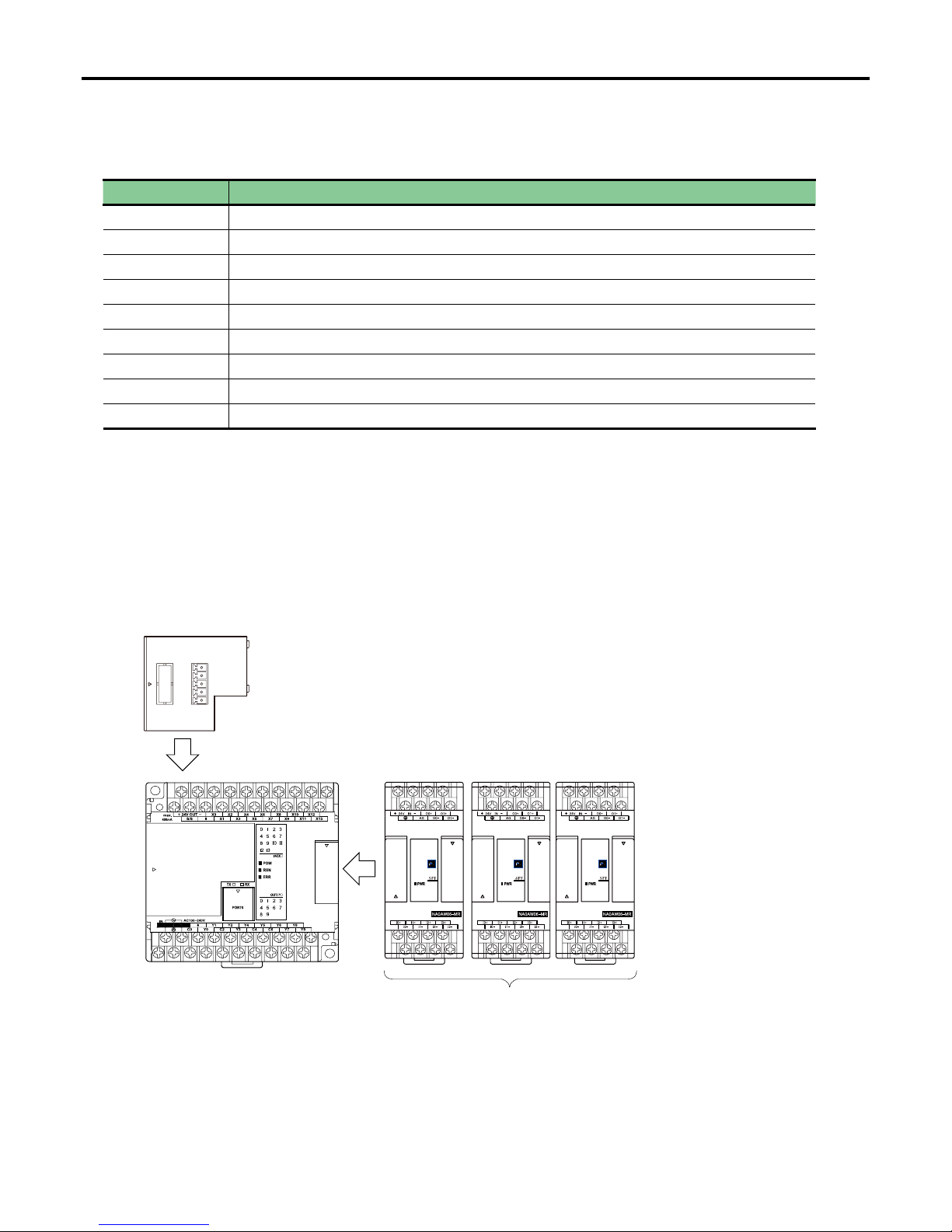
The analog unit is an expansion unit that is connected on the right-hand side of the SPF series main unit.
However, a front board type unit is connected on the front of the main unit.
For the front board type unit, only one unit can be connected on the main unit. For the other analog units, up to three units can
be connected on the right-hand side of the main unit.
Main unit
Analog unit (front board type)
Analog unit Analog unit Analog unit
Max. 3 units
Max. 1 unit
Page 9

1-2
Section 1 Overview
1-2-2 Analog signal range setting function
You can set the analog input and analog output signal range by using the jumper pin of the analog unit. Therefore, a program for
the range setting is not required.
1-2-3 Parameter setting function
You can set the parameters of the analog unit by using a program loader. The parameter setting items are as follows:
• Analog input unit (Type: NA0AX06-MR): Moving average, resolution
• Analog input/output unit (Type: NA0AW06-MR): Moving average, resolution (for analog input only)
• Analog input/output board (Type: NA3AW03-MR): Moving average, resolution (for analog input only)
• Thermocouple input unit (Type: NA0AX02-TC/NA0AX06-TC/NA0AX16-TC)
: Thermocouple type, moving average, sampling period (resolution), unit (Celsius or Fahrenheit)
• Resistance thermometer element input unit (NA0AX06-PT)
: Resistance thermometer element type, moving average, sampling period, unit (Celsius or Fahrenheit)
1-3 Supported Versions
1-3-1 Supported version of program loader
• SX-Programmer Expert (D300win) : V3.6.11 or later
• SX-Programmer Standard : V3.0.16 or later
1-3-2 Supported version of main unit
• V03 or later software version of the main units support analog boards that are connected on the front of them (Type:
NA3AY02-MR, NA3AW03-MR). Analog boards cannot be used with a main unit the software version of which is earlier than
V03.
Page 10

2-1
Section 2 Specications
Item Specication Remark
Physical
environmental
conditions
Operating ambient
temperature
0 to +55°C IEC 61131-2
Storage (transportation)
temperature
-25 to +70°C
Relative humidity
20 to 95%RH, no condensation
(Transport condition: 5 to 95%RH, no condensation)
Pollution degree 2 (Note 1)
Corrosion immunity Free from corrosive gases. Not stained with organic solvents
Operating altitude 2000 m or less above sea level (Transport condition: 70 kPa or more)
Mechanical
service
conditions
Vibration
Half amplitude: 0.15mm, Constant acceleration: 19.6 m/s
2
Two hours for each of three mutually perpendicular axes, total six
hours. (Note 2) (Note 3)
Shock
Acceleration peak: 98 m/s
2
Three times for each of three mutually perpendicular axes.
Electrical
service
conditions
Electrostatic discharge Contact discharge: ±4kV, Aerial discharge: ±8kV IEC 61000-4-2
Radiated,
radio-frequency,
electromagnetic eld
80 to 1000MHz (10V/m)
1.4 to 2.0 GHz (3V/m)
2.0 to 2.7 GHz (1V/m)
IEC 61000-4-3
EFT/B (Electrical fast
transient/burst)
Equipment power, I/0 power, AC I/O (unshielded): ±2kV
Data communication, digital and analog I/O s’ (except AC unshielded
I/O): ±1kV
IEC 61000-4-4
Lightning impulse surge
AC equipment power: ±2kV common mode, ±1kV differential mode
DC equipment power: ±0.5kV common mode, ±0.5kV differential mode
IEC 61000-4-5
Conducted radio
frequency
150kHz to 80MHz, 10V IEC 61000-4-6
Power frequency
magnetic eld
50Hz, 30A/m IEC 61000-4-8
Construction Panel-mounted type (open equipment)
Cooling Air cooling
2-1 General Specications
Notes:
1) Pollution degree 2: This pollution does not conduct usually, but under certain circumstances temporary conductivity occurs
due to condensation.
2) The unit is xed by screws to the control panel. When the unit is mounted to the DIN rail, care must be taken that
vibrations or shocks will not occur.
3) In an environment where repetitive or continuous vibration occurs, be sure to take vibration-proong measures.
Page 11

2-2
Section 2 Specications
2-2 Functional/Performance Specications
2-2-1 Specication list
(1) Analog input unit NA0AX06-MR
Item Specication
Type NA0AX06-MR
No. of input channels 6 channels
Input impedance Voltage: 63.2 kW, Current: 250
W
Maximum allowable input Voltage: ±15V, Current: ±30mA
Analog input range
-10 to +10V, -5 to +5V, 0 to 10V, 0 to 5V
-20 to 20mA, -10 to 10mA, 0 to 20mA, 0 to 10mA
(Collectively set for all channels by the jumper pin in the unit)
Resolution 12 bits or 14 bits (Set for individual channels by the program loader.)
Overall accuracy ±1% *1
A/D conversion value INT type
Sampling period Synchronized with the scan of the main unit.
Moving average 1 to 16 times (Set for individual channels by the program loader.)
External wire connections 8-pole terminal block (M3) x 2, Tightening torque: 0.59 to 0.78 N·m
Applicable wire size AWG#22-18 * Be sure to use shielded twisted pair cables.
Status indication 5V power supply display, ON when normal (red)
Isolation method Not isolated * For the internal circuit, see “Appendix 2.”
Occupied words 6 words
External power supply 24V DC, 53mA *Wiring length: 10m or less
Internal current consumption 5V DC, 25mA
Dimensions 40 (W) x 90 (H) x 80 (D) (mm)
Mass Approx. 160g
*1 The overall accuracy is the specication for when noise described in “Electrical service conditions” is not applied.
If noise is applied, the overall accuracy may exceed the above specication.
*2 Notes on using analog input
If connection between the analog unit and an external analog device is broken, the A/D conversion value (analog input
value) becomes 0 (zero).
Page 12

2-3
Section 2 Specications
Item Specication
Type NA0AY02-MR
No. of output channels 2 channels
External load resistance Voltage output: 500 W to 1 MW, Current output: 0 to 500 W or less
Analog output range
-10 to +10V, -5 to +5V, 0 to 10V, 0 to 5V
-20 to 20mA, -10 to 10mA, 0 to 20mA, 0 to 10mA
(Collectively set for all channels by the jumper pin in the unit)
Resolution 14 bits
Overall accuracy ±1%
Data type of digital output value INT type
Output period Synchronized with the scan of the main unit.
External wire connections 8-pole terminal block (M3) x 2, Tightening torque: 0.59 to 0.78 N·m
Applicable wire size AWG#22-18 * Be sure to use shielded twisted pair cables.
Status indication 5V power supply display, ON when normal (red)
Isolation method Not isolated * For the internal circuit, see “Appendix 2.”
Occupied words 2 words
External power supply 24V DC, 90mA *Wiring length: 10m or less
Internal current consumption 5V DC, 33mA
Dimensions 40 (W) x 90 (H) x 80 (D) (mm)
Mass Approx. 140g
(2) Analog output unit NA0AY02-MR
*1 Notes on using analog output
The analog unit does not support the hold function. If the main unit stops due to a system error, the analog output value
becomes 0 (zero). It is not possible to hold the output status after occurrence of an error or CPU stop.
Page 13

2-4
Section 2 Specications
Item Specication
Type NA0AW06-MR
No. of input channels 4 channels
Input impedance Voltage input: 63.2 kW, Current input: 250
W
Maximum allowable input Voltage: ±15V, Current: 30mA
Analog input range
-10 to +10V, -5 to +5V, 0 to 10V, 0 to 5V
-20 to 20mA, -10 to 10mA, 0 to 20mA, 0 to 10mA
(Collectively set for all channels by the jumper pin in the unit)
Resolution 12 bits or 14 bits (Set for each channel by the program loader.)
Overall accuracy ±1% *1
A/D conversion value INT type
Sampling cycle Synchronized with the scan of the main unit.
Moving average 1 to 16 times (Set for individual channels by the program loader.)
No. of output channels 2 channels
External load resistance Voltage output: 500 W to 1 MW, Current output: 0 to 500 W or less
Analog output range
-10 to +10V, -5 to +5V, 0 to 10V, 0 to 5V
-20 to 20mA, -10 to 10mA, 0 to 20mA, 0 to 10mA
(Collectively set for all channels by the jumper pin in the unit)
Resolution 14 bits
Overall accuracy ±1%
Data type of digital output value INT type
Output cycle Synchronized with the scan of the main unit.
External wire connections 8-pole terminal block (M3) x 2, Tightening torque: 0.59 to 0.78 N·m
Applicable wire size AWG#22-18 * Be sure to use shielded twisted pair cables.
Status indication 5V power supply display, ON when normal (red)
Isolation method Not isolated * For the internal circuit, see “Appendix 2.”
Occupied words 6 words
External power supply 24V DC, 103mA *Wiring length: 10m or less
Internal current consumption 5V DC, 35mA
Mass Approx. 160g
(3) Analog input/output unit NA0AW06-MR
*1 The overall accuracy is the specication for when noise described in “Electrical service conditions” is not applied.
If noise is applied, the overall accuracy may exceed the above specication.
*2 Notes on using analog input
If connection between the analog unit and an external analog device is broken, the A/D conversion value (analog input
value) becomes 0 (zero).
*3 Notes on using analog output
The analog unit does not support the hold function. If the main unit stops due to a system error, the analog output value
becomes 0 (zero). It is not possible to hold the output status after occurrence of an error or CPU stop.
Page 14

2-5
Section 2 Specications
Item Specication
Type NA3AY02-MR
No. of output channels 2 channels
External load resistance Voltage output: 1k W to 1MW, Current output: 0 to 500 W or less
Analog output range
0 to +10V
0 to 20mA
* Selectable by wiring of the terminal block.
Resolution 12 bits
Overall accuracy ±1%
Data type of digital output value INT type
Output period Synchronized with the scan of the main unit.
External wire connections 5-pole European-style terminal block (M2) x 1, Tightening torque: 0.2 N·m
Applicable wire size AWG#28-16 * Be sure to use shielded twisted pair cables.
Status indication None
Isolation method Not isolated
Occupied words 2 words
Internal current consumption 5V DC, 223mA
Mass Approx. 20g
(4) Analog output board, 2 channels NA3AY02-MR
*1 Tightening torque for mounting the board on the main unit: 0.2 N·m
*2 Notes on using analog output
The analog unit does not support the hold function. If the main unit stops due to a system error, the analog output value
becomes 0 (zero). It is not possible to hold the output status after occurrence of an error or CPU stop.
Page 15

2-6
Section 2 Specications
Item Specication
Type NA3AW03-MR
No. of input channels 2 channels
Input impedance Voltage input: 100 kW, Current input: 125
W
Maximum allowable input Voltage: ±15V, Current: 30mA
Analog input range
0 to +10V
0 to 20mA
* Selectable by wiring of the terminal block.
Resolution 14 bits (Set for each channel by the program loader.)
Overall accuracy ±1% *1
A/D conversion value INT type
Sampling cycle Synchronized with the scan of the main unit.
Moving average 1 to 16 times (Set for individual channels by the program loader.)
No. of output channels 1 channel
External load resistance Voltage output: 2 kW to 1 MW, Current output: 0 to 500 W or less
Analog output range
0 to +10V
0 to 20mA
* Selectable by wiring of the terminal block.
Resolution 12 bits
Overall accuracy ±1%
Data type of digital output value INT type
Output cycle Synchronized with the scan of the main unit.
External wire connections 5-pole European-style terminal block (M2) x 1, Tightening torque: 0.2 N·m
Applicable wire size AWG#28-16 * Be sure to use shielded twisted pair cables.
Status indication None
Isolation method Not isolated
Occupied words 3 words
Internal current consumption 5V DC, 158mA
Mass Approx. 20g
(5) Analog input/output board NA3AW03-MR
*1 The overall accuracy is the specication for when noise described in “Electrical service conditions” is not applied.
If noise is applied, the overall accuracy may exceed the above specication.
*2 Tightening torque for mounting the board on the main unit: 0.2 N·m
*3 Notes on using analog input
If connection between the analog unit and an external analog device is broken, the A/D conversion value (analog input
value) becomes 0 (zero).
*4 Notes on using analog output
The analog unit does not support the hold function. If the main unit stops due to a system error, the analog output value
becomes 0 (zero). It is not possible to hold the output status after occurrence of an error or CPU stop.
Page 16

2-7
Section 2 Specications
(6) Thermocouple input unit NA0AX02-TC/NA0AX06-TC/NA0AX16-TC
Item Specication
Type NA0AX02-TC NA0AX06-TC NA0AX16-TC
No. of input channels 2 channels 6 channels 16 channels
Resolution 0.1°C or 1°C *1
Thermocouple type J, K, R, S, E, T, B, N (Collectively set for all channels by the program loader.)
Temperature measurement
range
J: -200.0 to 1200.0°C -328.0 to 2192.0°F
K: -200.0 to 1200.0°C -328.0 to 2192.0°F
T: -190.0 to 380.0°C -310.0 to 716.0°F
E: -190.0 to 1000.0°C -310.0 to 1832.0°F
N: -200.0 to 1000.0°C -328.0 to 1832.0°F
B: 350.0 to 1800.0°C 622.0 to 3272.0°F
R: 0.0 to 1800.0°C 32.0 to 3272.0°F
S: 0.0 to 1700.0°C 32.0 to 3092.0°F
Cold junction automatic
compensator
Built in the unit
Overall accuracy
± (1% + 1°C) *2
Data type of
A/D conversion value
INT type
Sampling period
1 second (high speed) or
2 seconds (low speed)
2 seconds (high speed) or
4 seconds (low speed)
3 seconds (high speed) or
6 seconds (low speed)
(Collectively set [high speed or low speed] for all channels by the program loader.)
Moving average No moving average / 2 / 4 / 8 times
(Collectively set for all channels by the program loader.)
External wire connections 8-pole European-style terminal block (M2) x 2,
Tightening torque: 0.2 N·m
18-pole terminal block (M3) x 2,
Tightening torque:
0.59 to 0.78 N·m
Applicable wire size AWG#28-16 AWG#22-18
Status indication 5V power supply display, ON when normal (red)
Isolation method
Transformer (power supply) and photocoupler (signal) Not isolated
* For the internal circuit, see “Appendix 2.”
Occupied words 2 words 6 words 16 words
External power supply
24V DC, 21mA 24V DC, 29mA 24V DC, 58mA
*Wiring length: 10m or less
Internal current
consumption
5V DC, 30mA
Dimensions 40 (W) x 90 (H) x 80 (D) (mm) 90 (W) x 90 (H) x 80 (D) (mm)
Mass Approx. 130g Approx. 140g Approx. 310g
*1 The resolution is determined by the setting of the “sampling period” in the parameter.
When the resolution is 1°C: Set to “high speed.”
When the resolution is 0.1°C: Set to “low speed.”
*2 The overall accuracy is the specication for when noise described in “Electrical service conditions” is not applied.
If noise is applied, the overall accuracy may exceed the above specication.
*3 Immediately after the main unit is powered on, the A/D conversion value becomes “-32767” until the analog unit collects
analog values from external devices and starts A/D conversion (approx. 10 seconds.)
*4 If connection between the analog unit and a temperature sensor is broken, the temperature conversion value becomes
“28767.”
Page 17

2-8
Section 2 Specications
(7) Resistance thermometer element input unit NA0AX06-PT
Item Specication
Type NA0AX06-PT
No. of analog input channels 6 channels
Resolution 0.1°C or 1°C *1
Applicable resistance thermometer
element
Pt100, Pt1000 (JIS or DIN)
Temperature measurement range
Pt100: -200.0 to 850.0°C (-328.0 to 1562.0°F)
Pt1000: -200.0 to 600.0°C (-328.0 to 1112.0°F)
Overall accuracy ±1% *2
Resistance of input wiring 20Ω or less
Data type of A/D conversion value INT type
Sampling period
1 second (high speed) or 2 seconds (low speed)
(Collectively set for all channels by the program loader.)
Moving average
No moving average / 2 / 4 / 8 times
(Collectively set for all channels by the program loader.)
External wire connections 8-pole terminal block (M3) x 2, Tightening torque: 0.59 to 0.78 N·m
Applicable wire size AWG#22-18 * Be sure to use shielded twisted pair cables.
Status indication 5V power supply display, ON when normal (red)
Isolation method Not isolated * For the internal circuit, see “Appendix 2.”
Occupied words 6 words
External power supply 24V DC, 16mA *Wiring length: 10m or less
Internal current consumption 5V DC, 32mA
Dimensions 40 (W) x 90 (H) x 80 (D) (mm)
Mass Approx. 140g (excl. expansion cable)
*1 The resolution is determined by the setting of the “sampling period” in the parameter.
When the resolution is 1°C: Set to “high speed.”
When the resolution is 0.1°C: Set to “low speed.”
*2 The overall accuracy is the specication for when noise described in “Electrical service conditions” is not applied.
If noise is applied, the overall accuracy may exceed the above specication.
*3 Immediately after the main unit is powered on, the A/D conversion value becomes “-32767” until the analog unit collects
analog values from external devices and starts A/D conversion (approx. 10 seconds.)
*4 If connection between the analog unit and a temperature sensor is broken, the temperature conversion value becomes
“28767.”
Page 18
2-9
Section 2 Specications
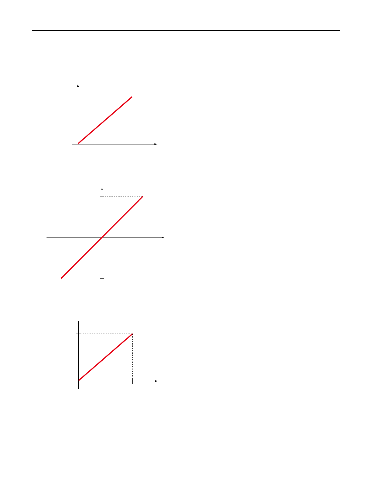
2-2-2 Conversion characteristics
(1) Analog input
1) 0 to 5V / 0 to 10mA (when set at UNIPOLAR)
3) 0 to 10V / 0 to 20mA (when set at UNIPOLAR)
2) 0 to 5V / 0 to 10mA (when set at BIPOLAR)
8191 (2047)
0
5V/10mA
0V/0mA
-8192 (-2048)
A/D conversion value
(INT type)
Analog input
voltage/current
* The values in ( ) are the A/D conversion value
s
when “12 bits” is selected for the resolution.
(4095) 16383
0
10V/20mA
A/D conversion value
(INT type)
Analog input
voltage/current
*1: The value in ( ) is the A/D conversion value
when “12 bits” is selected for the resolution
.
*2: 16380 for a front board
*2
(4095) 16383
A/D conversion value
(INT type)
Analog input
voltage/current
0
5V/10mA
* The value in ( ) is the A/D conversion value
when “12 bits” is selected for the resolution.
Page 19

2-10
Section 2 Specications
5) -5 to 5V / -10 to 10mA (when set at UNIPOLAR)
4) 0 to 10V / 0 to 20mA (when set at BIPOLAR)
6) -5 to 5V / -10 to 10mA (when set at BIPOLAR)
8191 (2047)
0
10V/20mA
0V/0mA
-8192 (-2048)
A/D conversion value
(INT type)
Analog input
voltage/current
* The values in ( ) are the A/D conversion value
s
when “12 bits” is selected for the resolution.
(4095) 16383
0
5V/10mA
-5V/-10mA
A/D conversion value
(INT type)
Analog input
voltage/current
* The value in ( ) is the A/D conversion value
when “12 bits” is selected for the resolution.
8191 (2047)
0
5V/10mA
-5V/-10mA
-8192 (-2048)
A/D conversion value
(INT type)
Analog input
voltage/current
* The values in ( ) are the A/D conversion value
s
when “12 bits” is selected for the resolution.
Page 20

2-11
Section 2 Specications
7) -10 to 10V / -20 to 20mA (when set at UNIPOLAR)
8) -10 to 10V / -20 to 20mA (when set at BIPOLAR)
(4095) 16383
(2047) 8191
0
10V/20mA
-10V/-20mA
A/D conversion value
(INT type)
Analog input
voltage/current
* The values in ( ) are the A/D conversion value
s
when “12 bits” is selected for the resolution.
8191 (2047)
0
10V/20mA
-10V/-20mA
-8192 (-2048)
A/D conversion value
(INT type)
Analog input
voltage/current
* The values in ( ) are the A/D conversion value
s
when “12 bits” is selected for the resolution.
Page 21

2-12
Section 2 Specications
(2) Analog output
1) 0 to 5V / 0 to 10mA (when set at UNIPOLAR)
16383
0
5V/10mA
Analog output
voltage/current
D/A
conversion value
(INT type)
3) 0 to 10V / 0 to 20mA (when set at UNIPOLAR)
2) 0 to 5V / 0 to 10mA (when set at BIPOLAR)
8191
5V/10mA
0V/0mA
-8192
Analog output
voltage/current
D/A
conversion value
(INT type)
16383
0
10V/20mA
Analog output
voltage/current
D/A
conversion value
(INT type)
* 16380 for a front board
Page 22

2-13
Section 2 Specications
4) 0 to 10V / 0 to 20mA (when set at BIPOLAR)
5) -5 to 5V / -10 to 10mA (when set at UNIPOLAR)
6) -5 to 5V / -10 to 10mA (when set at BIPOLAR)
8191
10V/20mA
0V/0mA
-8192
Analog output
voltage/current
D/A
conversion value
(INT type)
16383
0
5V/10mA
-5V/-10mA
Analog output
voltage/current
D/A conversion value
(INT type)
8191
0
5V/10mA
-5V/-10mA
-8192
Analog output
voltage/current
D/A
conversion value
(INT type)
Page 23

2-14
Section 2 Specications
7) -10 to 10V / -20 to 20mA (when set at UNIPOLAR)
8) -10 to 10V / -20 to 20mA (when set at BIPOLAR)
16383
0
10V/20mA
-10V/-20mA
Analog output
voltage/current
D/A
conversion value
(INT type)
8191
0
10V/20mA
-10V/-20mA
-8192
Analog output
voltage/current
D/A
conversion value
(INT type)
Page 24

2-15
Section 2 Specications
2-3 Names and Functions
2-3-1 Analog input unit (Type: NA0AX06-MR)
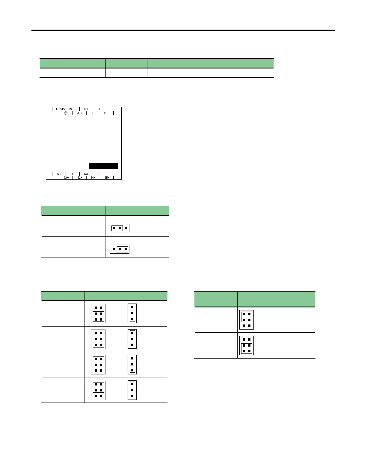
(1) Names
The jumper pins in the analog input unit are used to change the analog signal range and digital value range. Therefore, remove
the upper cover and control board when setting the jumper pin.
Pin layout of control board
(When the upper cover is removed)
Pin layout of I/O board
(When the control board is removed)
2) Terminal block
1) Status indication LED
Nameplate
Expansion connector (IN)
Expansion connector (OUT)
3) JP1
2) Terminal block
4) JP3
5) JP5 (CH1)
5) JP5 (CH0)
4) JP2
5) JP8 (CH4)
5) JP9 (CH5)
5) JP7 (CH3)
5) JP6 (CH2)
<Notes on mounting/removing the upper cover and control board>
• When handling the analog unit, remove it from the control panel, turn off the power, and disconnect other units.
• The procedure for handling the upper cover and printed circuit board, see “Appendix 1 Unit Handling Procedure.”
• Before mounting/removing the upper cover or handling the printed circuit board, be sure to eliminate static electricity.
Page 25
2-16
Section 2 Specications
Status indication LED Status Specication
PWR of analog input unit ON (red) While 5V DC power is normally supplied.
Digital value range JP1 setting
-8192 to 8191
0 to 16383
Signal range JP3 setting JP2 setting
0 to 10V
or
0 to 20mA
0 to 5V
or
0 to 10mA
-10 to 10V
or
-20 to 20mA
-5 to 5V
or
-10 to 10mA
Voltage/current
Setting of
JP4 (CH0) to JP9 (CH5)
Voltage
Current
(2) Functions
1) Status indication LED
2) Terminal block
These are terminals for 24V DC power supply to operate the analog unit and analog input signal.
3) JP1: Digital value range selection
This jumper pin is used to set the digital value range.
4) JP2 and JP3: Analog input range selection
These jumper pins are used to set the analog signal range
for six channels in a batch.
5) JP4 to 9: Voltage/current selection
This jumper pin is used to select voltage or current for
each channel.
* For the wiring method, see “2-4 Wiring.”
B
U
B
U
B
U
5V
10V
B
U
5V
10V
B
U
5V
10V
B
U
5V
10V
VIV
I
NA0AX06-MR
* When handling the setting pins on the printed circuit board, be sure to turn OFF the unit power. Securely mount them by using
tweezers.
Page 26

2-17
Section 2 Specications
2-3-2 Analog output unit (Type: NA0AY02-MR)
(1) Names
The jumper pins in the analog output unit are used to change the analog signal range and digital value range. Therefore, remove
the upper cover and control board when setting the jumper pin.
NA0AY02-MR
3) JP1
5) JPA (CH1)
5) JPA (CH0)
4) JPB (CH0)
4) JPB (CH1)
2) Terminal block
1) Status indication LED
Nameplate
Expansion connector (IN)
Expansion connector (OUT)
2) Terminal block
Pin layout of control board
(When the upper cover is removed)
<Notes on mounting/removing the upper cover and control board>
• When handling the analog unit, remove it from the control panel, turn off the power, and disconnect other units.
• The procedure for handling the upper cover and printed circuit board, see “Appendix 1 Unit Handling Procedure.”
• Before mounting/removing the upper cover or handling the printed circuit board, be sure to eliminate static electricity.
Page 27

2-18
Section 2 Specications
Status indication LED Status Specication
PWR of analog output unit ON (red) While 5V DC power is normally supplied.
(2) Functions
1) Status indication LED
2) Terminal block
These are terminals for 24V DC power supply to operate the analog unit and analog input signal.
* For the wiring method, see “2-4 Wiring.”
3) JP1: Digital value range selection
This jumper pin is used to set the digital value range.
4) JPA and JPB: Analog output range selection
B
U
B
U
U
B
5V
10V
U
B
5V
10
V
U
B
5V
10V
U
B
5V
10
V
U
B
5V
10
V
U
B
5V
10
V
U
B
5V
10
V
U
B
5V
10V
V
I
V
I
* When handling the setting pins on the printed circuit board, be sure to turn OFF the unit power. Securely mount them by using
tweezers.
Digital value range JP1 setting
-8192 to 8191
0 to 16383
Signal range JPA setting JPB setting
0 to 10V
-10 to 10V
0 to 5V
-5 to 5V
0 to 20mA
-20 to 20mA
0 to 10mA
-10 to 10mA
Page 28

2-19
Section 2 Specications
2-3-3 Analog input/output unit (Type: NA0AW06-MR)
(1) Names
The jumper pins in the analog input/output unit are used to change the analog signal range and digital value range. Therefore,
remove the upper cover and control board when setting the jumper pin.
NA0AW06-MR
3) JP1
JP1
D/A
A/D
B
U
B
U
B
U
10V
5V
I
V
CH0
CH1
4) JPA
6) JP3
6) JP4
U
B
5V
10V
I
V
CH0
CH1
5) JPB
7) JP5 (CH0) to JP8 (CH3)
10V
5V
B
U
2) Terminal block
1) Status indication LED
Nameplate
Expansion connector (IN)
Expansion connector (OUT)
2) Terminal block
Pin layout of control board
(When the upper cover is removed)
Pin layout of I/O board
(When the control board is removed)
<Notes on mounting/removing the upper cover and control board>
• When handling the analog unit, remove it from the control panel, turn off the power, and disconnect other units.
• The procedure for handling the upper cover and printed circuit board, see “Appendix 1 Unit Handling Procedure.”
• Before mounting/removing the upper cover or handling the printed circuit board, be sure to eliminate static electricity.
Page 29

2-20
Section 2 Specications
Status indication LED Status Specication
PWR of analog input/output unit ON (red) While 5V DC power is normally supplied.
(2) Functions
1) Status indication LED
2) Terminal block
These are terminals for 24V DC power supply to operate the analog unit and analog input signal.
* For the wiring method, see “2-4 Wiring.”
3) JP1: Digital value range selection
This jumper pin is used to set the digital value range for analog output (upper side) and analog input (lower side)
U
B
Analog output
Analog input
U
B
Analog output
Analog input
4) JPA and 5) JPB: Analog output range selection
U
B
5V
10
V
U
B
5V
10
V
U
B
5V
10
V
U
B
5V
10
V
U
B
5V
10
V
U
B
5V
10V
U
B
5V
10
V
U
B
5V
10
V
V
I
V
I
* When handling the setting pins on the printed circuit board, be sure to turn OFF the unit power. Securely mount them by using
tweezers.
Digital value range JP1 setting
-8192 to 8191
0 to 16383
Signal range JPA setting JPB setting
0 to 10V
-10 to 10V
0 to 5V
-5 to 5V
0 to 20mA
-20 to 20mA
0 to 10mA
-10 to 10mA
Page 30

2-21
Section 2 Specications
6) JP3 and JP4: Analog input range selection
U
B
5V
10V
U
B
5V
10V
U
B
5V
10V
U
B
5V
10V
7) JP5 to 8: Input voltage/current selection
This jumper pin is used to select voltage or current for each channel.
I
V
I
V
* When handling the setting pins on the printed circuit board, be sure to turn OFF the unit power. Securely mount them by using
tweezers.
Signal range JP3 setting JP4 setting
0 to 10V
or
0 to 20mA
0 to 5V
or
0 to 10mA
-10 to 10V
or
-20 to 20mA
-5 to 5V
or
-10 to 10mA
Voltage/current
Setting of
JP5 (CH0) to JP8 (CH3)
Voltage
Current
Page 31

2-22
Section 2 Specications
2-3-4 Analog output board (Type: NA3AY02-MR)
(1) Names
1) Terminal block
GND
VO0+
IO0+
VO1+
IO1+
(2) Functions
1) Terminal block
These are terminals for analog output signal. (M2, 5-pole terminal block x 1) Tightening torque: 0.2 N·m
* For the wiring method, see “2-4 Wiring.”
2-3-5 Analog input/output board (Type: NA3AW03-MR)
(1) Names
GND
VO0+
IO0+
GND
VI0+
II0+
VI1+
II1+
1) Terminal block
(2) Functions
1) Terminal block
These are terminals for analog input/output signal. (M2, 5-pole terminal block x 2) Tightening torque: 0.2 N·m
* For the wiring method, see “2-4 Wiring.”
<Notes on handling a front board>
Before handling a front board, be sure to eliminate static electricity.
Page 32

2-23
Section 2 Specications
2-3-6 Thermocouple input unit (Type: NA0AX02-TC/NA0AX06-TC/NA0AX16-TC)
(1) Names
2) Terminal block
1) Status indication LED
Nameplate
Expansion
connector (IN)
Expansion
connector (OUT)
2) Terminal block
2) Terminal block
NA0AX02-TC
NA0AX16-TC
NA0AX06-TC
1) Status indication LED
2) Terminal block
2) Terminal block
1) Status indication LED
Nameplate
Expansion
connector (IN)
Expansion
connector (IN)
Expansion
connector (OUT)
Nameplate
Expansion
connector (OUT)
Page 33

2-24
Section 2 Specications
Status indication LED Status Specication
PWR of thermocouple input unit ON (red) While 5V DC power is normally supplied.
(2) Functions
1) Status indication LED
2) Terminal block
These are terminals for 24V DC power supply to operate the unit and thermocouple input signal.
* For the wiring method, see “2-4 Wiring.”
* When performing wiring of NA0AX02-TC and NA0AX06-TC, take extra care not to scratch the parts boxed in red in the gure
below with the tip of the screwdriver, and not to enter wiring waste inside the unit. Otherwise, a fault may occur.
Page 34

2-25
Section 2 Specications
2-3-7 Resistance thermometer element input unit (Type: NA0AX06-PT)
(1) Names
2) Terminal block
1) Status indication LED
Nameplate
Expansion connector (IN)
Expansion connector (OUT)
2) Terminal block
Status indication LED Status Specication
PWR of resistance thermometer element input unit ON (red) While 5V DC power is normally supplied.
(2) Functions
1) Status indication LED
2) Terminal block
These are terminals for 24V DC power supply to operate the unit and sensor input.
* For the wiring method, see “2-4 Wiring.”
Page 35

2-26
Section 2 Specications
2-4 Wiring
2-4-1 Analog input
(1) Target type: NA0AX06-MR/NA0AW06-MR
V
I5
I
I5+
AG
I1+
V
I
I1
V
I
I0
I0+
15V
+15V
24V
24V+
CH0
CH1
NA0AX06-MR/NA0AW06-MR
CH5
-
+
-
+
-
+
* Up to CH3 for NA0AW06-MR
shielded twisted pair cable
Analog device
(Example of voltage input
)
(Example of current input)
Analog device
shielded twisted pair cable
shielded twisted pair cable
Analog device
Voltage/current selection
(Example of voltage input
)
+24V DC
External power supply
*1 Unused channels shall basically be short-circuited.
*2 Ground shielded wires at one point on the PLC side (Grounding resistance of 100Ω or less). However, when shielded wires
had better be grounded on the external device side due to the condition of external noise, their ends on the PLC side must
be open.
*3 Keep signal wires that go out of the analog unit sufciently away from high-voltage or power cables, and avoid parallel wiring.
*4 Avoid wiring the signal cables in the vicinity of load cables coming from devices other than PLC or bundling them with such
cables.
*5 Keep the signal cables sufciently away from circuits where high frequencies occur, such as inverter main load circuit.
Page 36

2-27
Section 2 Specications
(2) Target type: NA3AW03-MR
+
+
II1+
VI0+
CH0
*6
CH1
NA3AW03-MR
GND
II0+
VI1+
75k
25k
125
shielded twisted pair cable
For voltage
For current
Analog device
Analog device
(Example of voltage input)
(Example of current input)
shielded twisted pair cable
*1 Unused channels shall basically be short-circuited. (Voltage signal terminal - Current signal terminal - GND)
The signal terminal on the unused side of the used channel must be open.
Example: When CH0 is used as voltage input, II0+ terminal must be open.
*2 Ground shielded wires at one point on the PLC side (Grounding resistance of 100Ω or less). However, when shielded wires
had better be grounded on the external device side due to the condition of external noise, their ends on the PLC side must
be open.
*3 Keep signal wires that go out of the analog unit sufciently away from high-voltage or power cables, and avoid parallel wiring.
*4 Avoid wiring the signal cables in the vicinity of load cables coming from devices other than PLC or bundling them with such
cables.
*5 Keep the signal cables sufciently away from circuits where high frequencies occur, such as inverter main load circuit.
*6 It is recommended to connect a ceramic capacitor (0.1 to 0.4μF) to reduce noise.
Page 37

2-28
Section 2 Specications
2-4-2 Analog output
(1) Target type: NA0AY02-MR and NA0W06-MR
V
O1+
I
O1
AG
I
15V
+15V
24V
O0+
V
O0
24V+
NA0AY02-MR/NA0AW06-MR
CH0
shielded twisted pair cable
Analog device
(Example of voltage output
)
CH1
Analog device
(Example of current output)
Voltage/current selection
+24V DC
External power supply
*1 Unused channels shall basically be short-circuited.
*2 Ground shielded wires at one point on the PLC side (Grounding resistance of 100Ω or less). However, when shielded wires
had better be grounded on the external device side due to the condition of external noise, their ends on the PLC side must
be open.
*3 Keep signal wires that go out of the analog unit sufciently away from high-voltage or power cables, and avoid parallel wiring.
*4 Avoid wiring the signal cables in the vicinity of load cables coming from devices other than PLC or bundling them with such
cables.
*5 Keep the signal cables sufciently away from circuits where high frequencies occur, such as inverter main load circuit.
Page 38

2-29
Section 2 Specications
(2) Target type: NA3AY02-MR and NA0W03-MR
VO1+
VO0+
NA3AY02-MR/NA3AW03-MR
IO0+
IO1+
GND
CH0
*6
CH1
I
V
I
V
* Only CH0 for NA3AW03-MR
shielded twisted pair cable
Analog device
(Example of voltage output
)
(Example of current output)
Analog device
shielded twisted pair cable
*1 Unused channels shall basically be short-circuited.
*2 Ground shielded wires at one point on the PLC side (Grounding resistance of 100Ω or less). However, when shielded wires
had better be grounded on the external device side due to the condition of external noise, their ends on the PLC side must
be open.
*3 Keep signal wires that go out of the analog unit sufciently away from high-voltage or power cables, and avoid parallel wiring.
*4 Avoid wiring the signal cables in the vicinity of load cables coming from devices other than PLC or bundling them with such
cables.
*5 Keep the signal cables sufciently away from circuits where high frequencies occur, such as inverter main load circuit.
*6 It is recommended to connect a ceramic capacitor (0.1 to 0.4μF) to reduce noise.
Page 39

2-30
Section 2 Specications
2-4-3 Thermocouple input
(Target type: NA0AX02-TC/NA0AX06-TC/NA0AX16-TC)
Multiplexer
+
+
+
+24V DC
24V
24V+
TC15+
TC15-
+
TC1-
TC1+
+
TC0+
TC0-
+
NA0AX02-TC/NA0AX06-TC/NA0AX16-TC
External power supply
Thermocouple
sensor
Thermocouple
sensor
Thermocouple
sensor
* Up to TC1 for NA0AX02-TC
Up to TC5 for NA0AX06-TC
Page 40

2-31
Section 2 Specications
2-4-4 Resistance thermometer element input unit
Multiplexer
24V
24V+
P5+
P5
COM
P1
P1+
P0+
P0
PT
NA0AX06-PT
PT
+24V DC
External power supply
*1 When this unit is used under high noise environment, ground grounding terminal (grounding resistance of 100Ω or less).
*2 For wiring of Po+, Po-, and COM, use the same length of wires so that the impedance becomes equal.
Page 41

2-32
Section 2 Specications
2-5 Dimensions
2-5-1 Expansion unit 1
<Target type>
Type Specication
NA0AX06-MR Analog voltage/current input, 6 channels
NA0AY02-MR Analog voltage/current output, 2 channels
NA0AW06-MR Analog voltage/current input/output, Input 4 channels, Output 2 channels
NA0AX02-TC Thermocouple input, 2 channels
NA0AX06-TC Thermocouple input, 6 channels
NA0AX06-PT Resistance thermometer element input, 6 channels
2×Φ4.5
20
3.8
20
9.5 21
40
3.8
80
(97)
903
7.5
Unit: mm
Page 42

2-33
Section 2 Specications
Type Specication
NA0AX16-TC Thermocouple input, 16 channels
Type Specication
NA3AW03-MR Analog voltage/current input/output, Input 2 channels, Output 1 channel, Front board type
NA3AY02-MR Analog voltage/current output, 2 channels, Front board type
2-5-2 Expansion unit 2
<Target type>
21
4
4
2×Φ4.5
4
4
90
80
(97)
903
7.5
19.5
2-5-3 Front board
<Target type>
51
47
* The left gure shows the appearance of NA3AY02-MR. NA3AW03-MR has the
same dimensions.
* There is a screw hole for mounting a front board inside the cover.
Unit: mm
Unit: mm
Page 43

3-1
Section 3 Programming
3-1 Memory Assignment
3-1-1 Analog input unit NA0AX06-MR
WXo.0 CH0 A/D conversion value (INT type)
WXo.1 CH1 A/D conversion value (INT type)
WXo.2 CH2 A/D conversion value (INT type)
WXo.3 CH3 A/D conversion value (INT type)
WXo.4 CH4 A/D conversion value (INT type)
WXo.5 CH5 A/D conversion value (INT type)
WXo.0 CH0 A/D conversion value (INT type)
WXo.1 CH1 A/D conversion value (INT type)
WXo.2 CH2 A/D conversion value (INT type)
WXo.3 CH3 A/D conversion value (INT type)
WYo.4 CH4 D/A conversion value (INT type)
WYo.5 CH5 D/A conversion value (INT type)
WXo.0 CH0 A/D conversion value (INT type)
WXo.1 CH1 A/D conversion value (INT type)
WYo.2 CH2 D/A conversion value (INT type)
WYo.0 CH0 D/A conversion value (INT type)
WYo.1 CH1 D/A conversion value (INT type)
WYo.0 CH0 D/A conversion value (INT type)
WYo.1 CH1 D/A conversion value (INT type)
3-1-2 Analog output unit NA0AY02-MR
3-1-4 Analog output board NA3AY02-MR
3-1-3 Analog input/output unit NA0AW06-MR
3-1-5 Analog input/output board NA3AW03-MR
* The unit No. registered in the system denition is entered in o.
Page 44

3-2
Section 3 Programming
WXo.0 T0 Temperature conversion value (INT type)
WXo.1 T1 Temperature conversion value (INT type)
WXo.0 T0 Temperature conversion value (INT type)
WXo.1 T1 Temperature conversion value (INT type)
WXo.2 T2 Temperature conversion value (INT type)
WXo.3 T3 Temperature conversion value (INT type)
WXo.4 T4 Temperature conversion value (INT type)
WXo.5 T5 Temperature conversion value (INT type)
WXo.0 T0 Temperature conversion value (INT type)
WXo.1 T1 Temperature conversion value (INT type)
WXo.2 T2 Temperature conversion value (INT type)
WXo.3 T3 Temperature conversion value (INT type)
WXo.4 T4 Temperature conversion value (INT type)
WXo.5 T5 Temperature conversion value (INT type)
WXo.6 T6 Temperature conversion value (INT type)
WXo.7 T7 Temperature conversion value (INT type)
WXo.8 T8 Temperature conversion value (INT type)
WXo.9 T9 Temperature conversion value (INT type)
WXo.10 T10 Temperature conversion value (INT type)
WXo.11 T11 Temperature conversion value (INT type)
WXo.12 T12 Temperature conversion value (INT type)
WXo.13 T13 Temperature conversion value (INT type)
WXo.14 T14 Temperature conversion value (INT type)
WXo.15 T15 Temperature conversion value (INT type)
3-1-6 Thermocouple input unit NA0AX02-TC/NA0AX06-TC/NA0AX16-TC
(1) NA0AX02-TC
(2) NA0AX06-TC
(3) NA0AX16-TC
WXo.0 P0 Temperature conversion value (INT type)
WXo.1 P1 Temperature conversion value (INT type)
WXo.2 P2 Temperature conversion value (INT type)
WXo.3 P3 Temperature conversion value (INT type)
WXo.4 P4 Temperature conversion value (INT type)
WXo.5 P5 Temperature conversion value (INT type)
3-1-7 Resistance thermometer element input unit NA0AX06-PT
* The unit No. registered in the system denition is entered in o.
Page 45

3-3
Section 3 Programming
3-2 System Denition
3-2-1 Registering units
Connect the analog unit on the right of the main unit or the unit that is connected on the right of the main unit.
However, a front board type unit must be connected on the front of the main unit.
<Example of system conguration>
NA3AW03-MR
(Front board type)
NA0AX06-MR
Main unit
<How to register units>
1) Open the system denition screen and register the unit that is connected below the main unit (NA0AX06-MR in this example).
Right-click here.
2) Right-click the main unit and left-click [Insert]. The “Module insert” dialog box opens.
Select “NA0AX06-MR Analog Input 6CH” from the [Outline specication] box and then click the [OK] button. The unit is
registered.
Page 46

3-4
Section 3 Programming
3) Right-click the main unit and left-click [Insert]. The “Module insert” dialog box opens.
Select “Front Board” for the [Module group type], and “NA3AW03-MR Mixed Analog 3CH” from the [Outline specication] box.
Then, click the [OK] button. The unit is registered.
The front board is connected on the front of the main unit and registered below the expansion right side unit in the
conguration denition tree. The unit station No. is xed to “100.”
Page 47

3-5
Section 3 Programming
Parameter Setting range
Resolution 14 bits, 12 bits, or 14 bits (12 bits) *
Moving average execution times 1 (No moving average) to 16 times
3-2-2 Setting parameters
(1) Analog input unit (Target type: NA0AX06-MR, NA0AW06-MR, NA3AW03-MR)
For an analog input unit, set the resolution and moving average execution times.
* What does the “14 bits (12 bits)” of the resolution mean?
This means the resolution is 14 bits, however, the lower two bits are xed to 0. The A/D conversion value range is the same as
for 14 bits as shown below, however, the value increments or decrements by 4.
UNIPOLAR: 0 to 16000, BIPOLAR: -8000 to 8000
<How to set parameters>
1) Right-click the analog unit registered in the system denition screen and left-click [Properties]. The “Module properties” dialog
box opens.
* The setting procedure is the same for
a front board type unit.
Page 48

3-6
Section 3 Programming
2) Click the [Parameter] button to display the “Analog Input Unit parameter setting” dialog box.
Set the resolution (data format) and moving average for each channel, and then click the [OK] button.
Page 49

3-7
Section 3 Programming
(2) Thermocouple input unit (Target type: NA0AX02-TC, NA0AX06-TC, NA0AX16-TC)
For a thermocouple input unit, set the sensor type of the thermocouple, moving average execution times, sampling period, and
unit.
Parameter Setting range
Sensor type
J: -200 to 1200°C
K: -200 to 1200°C
T: -190 to 380°C
E: -190 to 1000°C
N: -200 to 1000°C
B: 350 to 1800°C
R: 0 to 1800°C
S: 0 to 1700°C
Moving average No moving average, 2, 4, or 8 times
Sampling period High speed or low speed
Unit Celsius or Fahrenheit
<How to set parameters>
1) Right-click the thermocouple input unit registered in the system denition screen and left-click [Properties]. The “Module
properties” dialog box opens.
2) Click the [Parameter] button to display the “Temperature Measurement Unit parameter setting” dialog box.
Set the sensor type, moving average, sampling period, and unit for all channels in a batch, and then click the [OK] button.
Page 50

3-8
Section 3 Programming
(3) Resistance thermometer element input unit (Target type: NA0AX06-PT)
For a resistance thermometer element input unit, set the sensor type of the resistance thermometer element, moving average
execution times, sampling period, and unit.
Parameter Setting range
Sensor type
PT100-DIN:
PT100-JIS:
PT1000-DIN:
PT1000-JIS:
Moving average No moving average, 2, 4, or 8 times
Sampling period High speed (1 second) or low speed (2 seconds)
Unit Celsius or Fahrenheit
<How to set parameters>
1) Right-click the thermocouple input unit registered in the system denition screen and left-click [Properties]. The “Module
properties” dialog box opens.
2) Click the [Parameter] button to display the “Temperature Measurement Unit parameter setting” dialog box.
Set the sensor type, moving average, sampling period, and unit for all channels in a batch, and then click the [OK] button.
Page 51

App.1-1
Appendix 1 Unit Handling Procedure
Appendix 1-1 Handling Upper Cover and Printed Circuit board
Appendix 1-1-1 Handling Upper Cover
(1) How to remove the upper cover
Notes:
Before mounting/removing the upper cover or handling the printed circuit board, be sure to eliminate static electricity.
Upper cover
Lower case
*
*
2)
Lightly turn the lower case of the unit and the upper cover in the direction of each arrow.
A small gap is made between one side of the lower case of the unit and the upper cover as shown below (see the area
marked with an asterisk).
1) Hold the unit with the both hands (with the nameplate facing forward) as shown below.
Hold the lower case with the left hand and the upper cover with the right hand.
Page 52

App.1-2
Appendix 1 Unit Handling Procedure
3) Pull the upper cover and the lower case of the unit to the right and left.
T
hen, the upper cover is removed from the lower case as shown below.
(2) How to mount the upper cover
1) Hold the lower case with the nameplate facing forward and the upper cover with the side having the larger notch up.
Then, mount the upper cover straight on the lower case (you will hear a clicking noise when inserted).
* The right and left notches of the upper cover are different in size.
Notes:
Before mounting/removing the upper cover or handling the printed circuit board, be sure to eliminate static electricity.
Page 53

App.1-3
Appendix 1 Unit Handling Procedure
Appendix 1-1-2 Handling Printed circuit board inside unit
(1) How to remove the printed circuit board
1) The image below shows the unit with the upper cover removed.
2)
The printed board is fixed at the printed board fixing hole of the lower case.
3) Pull the upper part of the lower case rightward and leftward, detach the printed board from the fixing hole, and then, pull
it out slowly.
(2) How to mount the printed circuit board
To mount the printed circuit board, reverse the order of removal described in (1).
Notes:
Before mounting/removing the upper cover or handling the printed circuit board, be sure to eliminate static electricity.
Page 54

App.2-1
Appendix 2 Circuit Isolation Block Diagram
Appendix 2-1 Analog Input Unit NA0AX06-MR
Appendix 2-2 Analog Output Unit NA0AY02-MR
Page 55

App.2-2
Appendix 2 Circuit Isolation Block Diagram
Appendix 2-3 Analog Input/Output Unit NA0AW06-MR
Appendix 2-4 Thermocouple Input Unit NA0AX02-TC/NA0AX06-TC
Page 56

App.2-3
Appendix 2 Circuit Isolation Block Diagram
Appendix 2-5 Thermocouple Input Unit NA0AX16-TC
Appendix 2-6 Resistance Thermometer Element Input Unit NA0AX06-PT
Page 57

Materials covered in this document are subject to revision due to the modication of the product.
Fuji Electric Co., Ltd.
Gate City Ohsaki, East Tower,
11-2, Osaki 1-chome, Shinagawa-ku, Tokyo 141-0032, Japan
E-mail: micrex-sx@fujielectric.com
URL: http://www.fujielectric.com/
 Loading...