

Fuji Electric FRN5.5LM1S-2, FRN15LM1S-2, FRN18.5LM1S-2, FRN22LM1S-2, FRN4.0LM1S-4 Instruction Manual
...Page 1

Designed for Elevating Machinery
Instruction Manual
Thank you for purchasing our FRENIC-Lift series of inverters.
• This product is designed to drive a three-phase induction motor and synchronous motor. Read through this
instruction manual and be familiar with the handling procedure for correct use.
• Improper handling might result in incorrect operation, a short life, or even a failure of this product as well as
the motor.
• Deliver this manual to the end user of this product. Keep this manual in a safe place until this product is
discarded.
• For how to use an option card, refer to the installation and instruction manuals for that option card.
Fuji Electric Co., Ltd. INR-SI47-1038g-E
Page 2

Copyright © 2005-2011 Fuji Electric Systems Co., Ltd.
All rights reserved.
No part of this publication may be reproduced or copied without prior written permission from Fuji Electric Co., Ltd.
All products and company names mentioned in this manual are trademarks or registered trademarks of their
respective holders.
The information contained herein is subject to change without prior notice for improvement.
Page 3
Preface
Thank you for purchasing our FRENIC-Lift series of inverters.
FRENIC-Lift is an inverter designed to drive a three-phase induction motor (hereafter called an induction motor)
and a three-phase permanent magnet synchronous motor (hereafter called a synchronous motor) for exclusively
controlling elevating machinery.
Improper handling might result in incorrect operation, a short life, or even a failure of this product as well as the
motor.
To drive a synchronous motor, a PG interface card option involving a pulse encoder is needed. For derails, refer
to the instruction manual of PG Interface Card.
Listed below are the other materials related to the use of the FRENIC-Lift. Read them in conjunction with this
manual as necessary.
• Multi-function Keypad "TP-G1-CLS" Instruction Manual (INR-SI47-1092-E)
• FRENIC-Lift Reference Manual (INR-SI47-1068-E)
• About compliance with standards (INR-SI47-1148-E)
The materials are subject to change without notice. Be sure to obtain the latest editions for use.
Safety precautions
Read this manual thoroughly before proceeding with installation, connections (wiring), operation, or maintenance
and inspection. Ensure you have sound knowledge of the device and familiarize yourself with all safety information and precautions before proceeding to operate the inverter.
Safety precautions are classified into the following two categories in this manual.
Failure to heed the information indicated by this symbol may lead to
dangerous conditions, possibly resulting in death or serious bodily injuries.
Failure to heed the information indicated by this symbol may lead to
dangerous conditions, possibly resulting in minor or light bodily injuries
and/or substantial property damage.
Failure to heed the information contained under the CAUTION title can also result in serious consequences.
These safety precautions are of utmost importance and must be observed at all times.
Application
• FRENIC-Lift is equipment designed to drive induction motors and synchronous motors for exclusively
controlling elevating machinery. Do not use it for single-phase motors or for other purposes.
Fire or accident could occur.
• FRENIC-Lift may not be used for a life-support system or other purposes directly related to the human
safety.
• Though FRENIC-Lift is manufactured under strict quality control, install safety devices for applications
where serious accidents or material losses are foreseen in relation to the failure of it.
An accident could occur.
i
Page 4
Installation
• Install the inverter on a nonflammable material such as metal.
Otherwise fire could occur.
• Do not place flammable matter nearby.
Doing so could cause fire.
• Using an optional DC reactor makes human body easily touch any live parts of inverters. In this case,
take countermeasures such as installing the inverter in a place that easily protects human body from
electric shock.
Otherwise, electric shock or injuries could occur.
• Do not touch the printed circuit boards in the product directly. Electronic devices on those boards are
easily affected by static electricity.
When touching those boards, put on a grounding wrist band and perform the job on a static mat.
Static electricity charged in your body may damage the product.
• Do not support the inverter by its terminal block cover during transportation.
Doing so could cause a drop of the inverter and injuries.
• Prevent lint, paper fibers, sawdust, dust, metallic chips, or other foreign materials from getting into the
inverter or from accumulating on the heat sink.
Otherwise, a fire or an accident might result.
• Do not install or operate an inverter that is damaged or lacking parts.
Doing so could cause fire, an accident or injuries.
• Do not get on a shipping box.
• Do not stack shipping boxes higher than the indicated information printed on those boxes.
Doing so could cause injuries.
Wiring
• When wiring the inverter to the power source, insert a recommended molded case circuit breaker
(MCCB) or residual-current-operated protective device (RCD)/earth leakage circuit breaker (ELCB)
(with overcurrent protection) in the path of power lines. Use the devices within the recommended current range.
• Use wires in the specified size.
Otherwise, fire could occur.
• Do not use one multicore cable in order to connect several inverters with motors.
• Do not connect a surge killer to the inverter's output (secondary) circuit.
Doing so could cause fire.
• Install inverters in compliance with the local regulation.
Otherwise, electric shock or fire could occur.
• Qualified electricians should carry out wiring.
• Be sure to perform wiring after turning the power OFF.
Otherwise, electric shock could occur.
• Be sure to perform wiring after installing the inverter body.
Otherwise, electric shock or injuries could occur.
ii
Page 5
• Ensure that the number of input phases and the rated voltage of the product match the number of
phases and the voltage of the AC power supply to which the product is to be connected.
Otherwise fire or an accident could occur.
• Do not connect the power source wires to output terminals (U, V, and W).
Doing so could cause fire or an accident.
• Generally, control signal wires are not enforced-insulated. If they accidentally touch any live power
lines, their insulation coat may break for any reasons. In such a case, an extremely high voltage may be
applied to the signal lines. Make a complete remedy to protect the signal line from contacting any live
high voltage lines.
Otherwise, an accident or electric shock could occur.
• Wire the three-phase motor to terminals U, V, and W of the inverter, aligning phases each other.
Otherwise injuries could occur.
• The inverter, motor and wiring generate electric noise. Take care of malfunction of the nearby sensors
and devices. To prevent the motor from malfunctioning, implement noise control measures.
Otherwise an accident could occur.
Operation
• Be sure to install the terminal block cover and the front cover before turning the power ON. Do not
remove the covers while power is applied.
Otherwise electric shock could occur.
• Do not operate switches with wet hands.
Doing so could cause electric shock.
• If the retry function has been selected, the inverter may automatically restart and drive the motor depending on the cause of tripping.
(Design the machinery or equipment so that human safety is ensured after restarting.)
• If the stall prevention function (current limiter), automatic deceleration, and overload prevention control
have been selected, the inverter may operate at an acceleration/deceleration time or frequency different from the commanded ones. Design the machine so that safety is ensured even in such cases.
Otherwise an accident could occur.
• If an alarm reset is made with the Run command signal turned ON, a sudden start will occur. Ensure that
the Run command signal is turned OFF in advance.
Otherwise an accident could occur.
• If you set the function codes wrongly or without completely understanding this instruction manual and
the FRENIC-Lift Reference Manual (INR-SI47-1068-E), the motor may rotate with a torque or at a
speed not permitted for the machine.
• In the tuning process of the inverter, no motor torque control for braking of the machinery takes effect.
Tune the inverter for the motor after disconnecting it from the machinery, or after mechanically brakes
the machinery. Anyway, do it after suppressing any dangerous factors.
An accident or injuries could occur.
• Never touch the inverter terminals while the power is applied to the inverter even if the inverter stops.
• Never touch the printed circuit boards in the product while the power is applied to the inverter. High
voltage is applied to those boards.
Doing so could cause electric shock.
iii
Page 6
• Do not turn the main circuit power (circuit breaker) ON or OFF in order to start or stop inverter operation.
Doing so could cause failure.
• Do not touch the heat sink because they become very hot.
Doing so could cause burns.
• Setting the inverter to high speeds is easy. Before changing the frequency (speed) setting, check the
specifications of the motor and machinery.
• The brake function of the inverter does not provide mechanical holding means.
Injuries could occur.
Setting control switches
• Before setting up any internal control switches, turn OFF the power, and wait for more than five minutes.
Further, check that the LED monitor is unlit, and make sure, using a multimeter or a similar instrument,
that the DC link bus voltage between the terminals P (+) and N (-) has dropped below a safe voltage
(+25 VDC).
Otherwise electric shock could occur.
Maintenance and inspection, and parts replacement
• Turn the power OFF and wait for more than five minutes, before starting inspection. Further, check that
the LED monitor is unlit, and check the DC link bus voltage between the P (+) and N (-) terminals to be
lower than 25 VDC.
Otherwise, electric shock could occur.
• Maintenance, inspection, and parts replacement should be made only by qualified persons.
• Take off the watch, rings and other metallic matter before starting work.
• Use insulated tools.
Otherwise, electric shock or injuries could occur.
Disposal
• Handle the inverter as an industrial waste when disposing of it.
Otherwise injuries could occur.
Others
• Never attempt to modify the inverter.
Doing so could cause electric shock or injuries.
Drawings in this manual may be illustrated without covers or safety shields for explanation of detail parts.
Restore the covers and shields in the original state and observe the description in the manual before
starting operation.
GENERAL PRECAUTIONS
iv
Page 7

Precautions for use
In running
generalpurpose
motors
In running
special motors
Driving a 400V
general-purpose
motor
Torque characteristics and temperature rise
Vibration
Noise
Brake motors
Geared motors
When driving a 400V general-purpose motor with an inverter using extremely long wires, damage to the insulation of the motor may occur. Apply
the inverter after consulting the motor maker.
When the inverter is used to run a general-purpose motor, the temperature
of the motor becomes higher than when it is operated using a commercial
power supply. In the low-speed range, the cooling effect will be weakened,
so decrease the output torque of the motor.
When an inverter-driven motor is mounted to a machine, resonance may
be caused by the natural frequencies of the machine system.
Note that operation of a 2-pole motor at 60 Hz or higher may cause abnormal vibration.
* The use of a rubber coupling or vibration dampening rubber is recom-
mended.
* Run your machinery including FRENIC-Lift inverter so as to skip its re-
sonance frequency zone/s.
When an inverter is used with a general-purpose motor, the motor noise
level is higher than that with a commercial power supply. To reduce noise,
raise carrier frequency of the inverter. Operation at 60 Hz or higher can
also result in higher noise level.
For motors equipped with parallel-connected brakes, their braking power
must be supplied from the primary circuit. If the brake power is connected
to the inverter's output circuit by mistake, the brake will not work.
Do not use inverters for driving motors equipped with series-connected
brakes.
If the power transmission mechanism uses an oil-lubricated gearbox or
speed changer/reducer, then continuous motor operation at low speed
may cause poor lubrication. Avoid such operation.
Environmental conditions
Synchronous motors
Single-phase
motors
Installation location
The PG interface card (option) corresponding to the pulse encoder specfication is necessary. Read PG interface card (option) manual.
Single-phase motors are not suitable for inverter-driven variable speed
operation. Use three-phase motors.
Use the inverter within the ambient temperature range from -10 to +45°C.
The heat sink and braking resistor of the inverter may become hot under
certain operating conditions, so install the inverter on nonflammable material such as metal.
Ensure that the installation location meets the environmental conditions
specified in Chapter 2, Section 2.1 "Operating Environment."
v
Page 8

Install a recommended molded case circuit breaker (MCCB) or resi-
Installing an
MCCB or
RCD/ELCB
dual-current-operated protective device (RCD)/earth leakage circuit
breaker (ELCB) (with overcurrent protection) in the primary circuit of the
inverter to protect the wiring. Ensure that the circuit breaker capacity is
equivalent to or lower than the recommended capacity.
Combination with
peripheral
devices
Installing an MC
in the secondary
circuit
Installing an MC
in the primary
circuit
Protecting the
motor
Discontinuance
of power-factor
correcting capacitor
Discontinuance
of surge killer
Reducing noise
If a magnetic contactor (MC) is mounted in the inverter's output (secondary) circuit, ensure that both the inverter and the motor are completely
stopped before you turn the MC on or off.
Remove a surge killer built-in the MC.
Do not turn the magnetic contactor (MC) in the primary circuit ON or OFF
more than once an hour as an inverter failure may result.
If frequent starts or stops are required during motor operation, use FWD /
REV signals.
The electronic thermal function of the inverter can protect the motor. The
operation level and the motor type (general-purpose motor, inverter motor)
should be set. For high-speed motors or water-cooled motors, set a small
value for the thermal time constant and protect the motor.
If you connect the motor thermal relay to the motor with a long wire, a
high-frequency current may flow into the wiring stray capacitance. This
may cause the relay to trip at a current lower than the set value for the
thermal relay. If this happens, lower the carrier frequency.
Do not mount power-factor correcting capacitors in the inverter’s primary
circuit. (Use the DC reactor to improve the inverter power factor.) Do not
use power-factor correcting capacitors in the inverter’s output (secondary)
circuit. An overcurrent trip will occur, disabling motor operation.
Do not connect a surge killer to the inverter's output (secondary) circuit.
Use of a filter and shielded wires is typically recommended to satisfy EMC
Directives.
Wiring
If an overvoltage trip occurs while the inverter is stopped or operated under
Measures against
surge currents
a light load, it is assumed that the surge current is generated by open/close
of the phase-advancing capacitor in the power system.
* Connect a DC reactor to the inverter.
When checking the insulation resistance of the inverter, use a 500 V
Megger test
megger and follow the instructions contained in Chapter 7, Section 7.5
"Insulation Test."
Control circuit
wiring length
When using remote control, limit the wiring length between the inverter and
operator box to 20 m or less and use twisted pair or shielded wire.
If long wiring is used between the inverter and the motor, the inverter will
Wiring length
between inverter
and motor
overheat or trip as a result of overcurrent (high-frequency current flowing
into the stray capacitance) in the wires connected to the phases. Ensure
that the wiring is shorter than 20 m. If this length must be exceeded, lower
the carrier frequency.
Wiring size
Wiring type
Select wires with a sufficient capacity by referring to the current value or
recommended wire size.
When several inverters drive motors, do not use one multicore cable in
order to connect several inverters with motors.
Grounding Securely ground the inverter using the grounding terminal.
vi
Page 9

Selecting
inverter
capacity
Transportation and
storage
Select an inverter according to the applicable motor ratings listed in the
Driving general-purpose motor
standard specifications table for the inverter.
When high starting torque is required or quick acceleration or deceleration
is required, select an inverter with a capacity one size greater than the
standard.
Driving special
motors
Select an inverter that meets the following condition:
Inverter rated current > Motor rated current
Halogen compounds such as methyl bromide used in fumigation corrodes some parts inside the
inverter. When exporting an inverter built in a panel or equipment, pack them in a previously
fumigated wooden crate. When packing an inverter alone for export, use a laminated veneer
lumber (LVL).
When transporting or storing inverters, follow the procedures and select locations that meet the
environmental conditions listed in Chapter 1, Section 1.3 "Transportation" and Section 1.4
"Storage Environment."
vii
Page 10

How this manual is organized
This manual is made up of chapters 1 through 9.
Chapter 1 BEFORE USING THE INVERTER
This chapter describes acceptance inspection and precautions for transportation and storage of the inverter.
Chapter 2 MOUNTING AND WIRING OF THE INVERTER
This chapter provides operating environment, precautions for installing the inverter, wiring instructions for the
motor and inverter.
Chapter 3 OPERATION USING THE KEYPAD
The FRENIC-Lift has no standard keypad. Operating the FRENIC-Lift from a keypad requires an optional multi-function keypad. For details in operations, refer to the Multi-function Keypad "TP-G1-CLS" Instruction Manual
(INR-S147-1092-E).
Chapter 4 RUNNING THE MOTOR
This chapter describes preparation to be made before running the motor for a test and practical operation.
Chapter 5 FUNCTION CODES
This chapter provides a list of the function codes. For details of function codes, refer to the FRENIC-Lift Reference Manual (INR-S147-1068-E.)
Chapter 6 TROUBLESHOOTING
This chapter describes troubleshooting procedures to be followed when the inverter malfunctions or detects an
alarm condition. In this chapter, first check whether any alarm code is displayed or not, and then proceed to the
troubleshooting items.
Chapter 7 MAINTENANCE AND INSPECTION
This chapter describes inspection, measurement and insulation test which are required for safe inverter operation.
It also provides information about periodical replacement parts and guarantee of the product.
Chapter 8 SPECIFICATIONS
This chapter lists specifications including output ratings, control system, external dimensions and protective
functions.
Chapter 9 LIST OF PERIPHERAL EQUIPMENT AND OPTIONS
This chapter describes main peripheral equipment and options which can be connected to the FRENIC-Lift series
of inverters.
Icons
The following icons are used throughout this manual.
This icon indicates information which, if not heeded, can result in the inverter not operating to full efficiency, as well as information concerning incorrect operations and settings which can result in accidents.
This icon indicates information that can prove handy when performing certain settings or operations.
This icon indicates a reference to more detailed information.
viii
Page 11

Table of Contents
Preface ................................................................... i
Safety precautions ............................................................. i
Precautions for use ........................................................... v
How this manual is organized .............................................viii
Chapter 1 BEFORE USING THE INVERTER .................. 1-1
1.1 Acceptance Inspection ........................................... 1-1
1.2 External View and Terminal Blocks ......................... 1-2
1.3 Transportation ........................................................ 1-4
1.4 Storage Environment .............................................. 1-4
1.4.1 Temporary storage ......................................... 1-4
1.4.2 Long-term storage ......................................... 1-4
Chapter 2 MOUNTING AND WIRING OF
2.1 Operating Environment .......................................... 2-1
2.2 Installing the Inverter .............................................. 2-1
2.3 Wiring ..................................................................... 2-5
2.4 Cautions Relating to Harmonic Component, Noise,
Chapter 3 OPERATION USING THE KEYPAD ............... 3-1
Chapter 4 RUNNING THE MOTOR ................................. 4-1
4.1 Running the Motor for a Test .................................. 4-1
4.2 Operation................................................................ 4-5
Chapter 5 FUNCTION CODES ........................................ 5-1
5.1 Function Code Tables ............................................. 5-1
THE INVERTER ............................................. 2-1
2.3.1 Removing and mounting the terminal block
(TB) cover and the front cover ....................... 2-5
2.3.2 Removing and retracting
the cable guide plate ...................................... 2-8
2.3.3 Terminal arrangement and
screw specifications ....................................... 2-9
2.3.4 Recommended wire sizes ............................ 2-12
2.3.5 Wiring precautions ....................................... 2-13
2.3.6 Wiring for main circuit terminals and
grounding terminals ..................................... 2-13
2.3.7 Wiring for control circuit terminals ................ 2-18
2.3.8 Setting up slide switches ............................. 2-27
and Leakage Current ............................................ 2-28
4.1.1 Inspection and preparation prior to
powering on ................................................... 4-1
4.1.2 Turning ON power and checking.................... 4-1
4.1.3 Preparation before running the motor
for a test--Setting function code data ............. 4-2
4.1.4 Test run .......................................................... 4-5
Chapter 6 TROUBLESHOOTING .................................... 6-1
6.1 Before Proceeding with Troubleshooting ................ 6-1
6.2 If No Alarm Code Appears on the LED Monitor ...... 6-2
6.2.1 Motor is running abnormally ........................... 6-2
6.2.2 Problems with inverter settings ...................... 6-6
6.3 If an Alarm Code Appears on the LED Monitor ....... 6-7
6.4 If an Abnormal Pattern Appears on the LED
Monitor while No Alarm Code is Displayed ........... 6-20
Chapter 7 MAINTENANCE AND INSPECTION ............... 7-1
7.1 Daily Inspection ...................................................... 7-1
7.2 Periodic Inspection ................................................. 7-1
7.3 List of Periodical Replacement Parts ...................... 7-3
7.3.1 Judgment on service life ................................ 7-3
7.4 Measurement of Electrical Amounts in
Main Circuit ............................................................ 7-5
7.5 Insulation Test ........................................................ 7-6
7.6 Inquiries about Product and Guarantee .................. 7-7
Chapter 8 SPECIFICATIONS .......................................... 8-1
8.1 Standard Models......................................................8-1
8.1.1Three-phase 200 V class series…………………8-1
8.1.2Three-phase 400 V class series…………………8-2
8.1.3Single-phase 200 V class series………………...8-3
8.2Common Specifications………………………………..8-4
8.3Terminal Specifications…………………………………8-5
8.3.1Terminal functions …………………………….8-5
8.3.2Basic wiring diagram …………………………….8-5
8.4External Dimensions…………………………………..8-7
8.4.1Standard models…………………………………8-7
8.5Protection Features………………………………….8-10
Chapter 9 LIST OF PERIPHERAL EQUIPMENT AND
OPTIONS ........................................................ 9-1
ix
Page 12
Chapter 1 BEFORE USING THE INVERTER
1.1 Acceptance Inspection
Unpack the package and check that:
(1) An inverter and accessories below are contained in the package.
• Cooling fan mounting screws (5.5 to 22 kW)
• Rubber bushes for cable guide plate (5.5 to 22 kW)
• Encoder wiring plug
(2) The inverter has not been damaged during transportation—there should be no dents or parts missing.
(3) The inverter is the model you ordered. You can check the model name and specifications on the main
nameplate. (Main and sub nameplates are attached to the inverter and are located as shown on the following
page.) For the inverter whose capacity is 37 kW or above, the mass of that is printed on the nameplate.
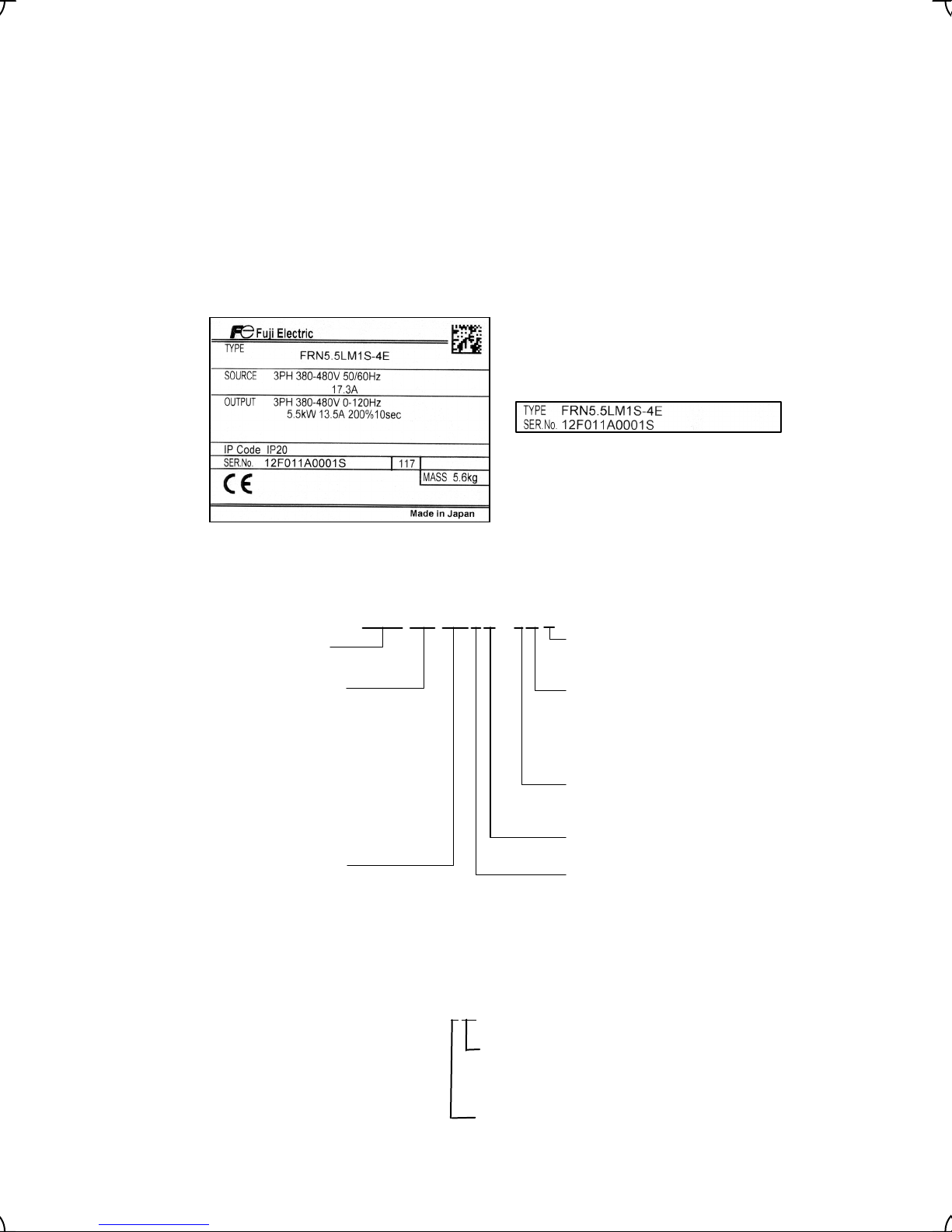
(a) Main Nameplate (b) Sub Nameplate
Figure 1.1 Nameplates
TYPE: Inverter model
F R N 5. 5 L M 1 S - 4 C
Code Series name
FRN FRENIC series
Code Nominal applied
motor
4.0 3.7 kW
5.5 5.5 kW
7.5 7.5 kW
11 11 kW
15 15 kW
18.5 18.5 kW
22 22 kW
30 30 kW
37 37 kW
45 45 kW
Code Applicable area
LM Elevating machinery
Code CAN port
With CAN port
(blank)
Without CAN port
A
Code Shipping destination/
Instruction manual version
C China/Chinese
E EU/English
A Asia/English
J Japan/Japanese
Code Power supply voltage
4 Three-phase 400 V
2 Three-phase 200 V
Code Enclosure
S Standard (IP20/IP00)
Code Development code
1 1
SOURCE: Number of input phases (three-phase: 3PH), input voltage, input frequency, input current
OUTPUT: Number of output phases, rated output capacity, rated output voltage, output frequency range, rated
output current, overload capacity
SER. No.: Product number manufacturing date
1 2 F 0 1 1 A 0 0 0 1 S 1 17
Production week
This indicates the week number that is numbered
from 1st week of January.
The 1st week of January is indicated as '01'.
Production year: Last digit of year
If you suspect the product is not working properly or if you have any questions about your product, contact your
Fuji Electric representative.
1-1
Page 13
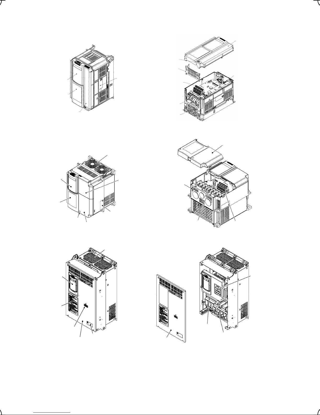
1.2 External View and Terminal Blocks
(1) Outside and terminal block views
Dummy cover
Warning plate
Front cover
Main nameplate
(a) FRN2.2LM1S-7. FRN4.0LM1S-4
Cooling fans
Front cover
Screw
Wiring guide
Sub nameplate
Control circuit
terminal block
Main circuit
terminal block
Cooling fans
Terminal block cover
Dummy cover
Warning plate
Dummy cover
Warning plate
Charging lamp
Note: A box (
Screw
Front cover
Main nameplate
Terminal block cover
Cable guide plate
Main circuit
terminal block
(b) FRN15LM1S-4
Front cover
Cooling fans
Main nameplate
Control circuit
terminal block
Front cover
(c) FRN30LM1S-4
Figure 1.2 Outside and Terminal Block Views of Inverters
) in the above figure replaces C, E, A or J depending on the shipping destination.
Control circuit
terminal block
Main circuit terminal block
Warning
plate
1-2
Page 14
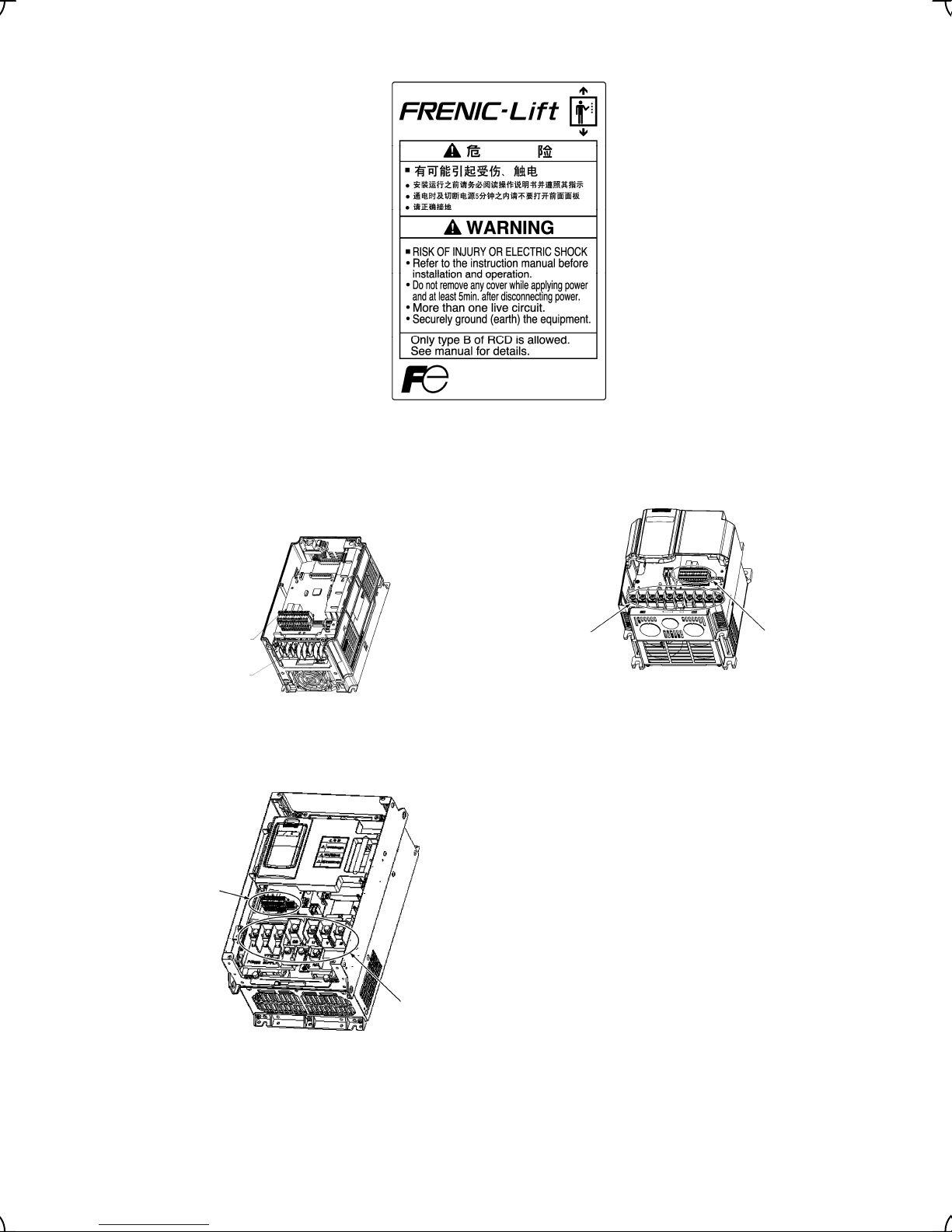
(2) Warning plates
(3) Terminal block location
Figure 1.3 Warning Plates
Control circuit
terminal block
Main circuit
terminal block
(a) FRN2.2LM1S-7, FRN4.0LM1S-4 (b) FRN15LM1S-4
Control circuit
terminal block
Note: A box (
Main circuit
terminal block
Control circuit
terminal block
Main circuit
terminal block
(c) FRN30LM1S-4
Figure 1.4 Main and Control Circuit Terminal Block Location
) in the above figure replaces C, E, A or J depending on the shipping destination.
1-3
Page 15

1.3 Transportation
• When carrying an inverter, always support its bottom at the front and rear sides with both hands. Do not hold
covers or individual parts only. You may drop the inverter or break it.
1.4 Storage Environment
1.4.1 Temporary storage
Store the inverter in an environment that satisfies the requirements listed in Table 1.1.
Table 1.1 Environmental Requirements for Storage and Transportation
Item Requirements
Storage temperature *1 -25 to +65°C
Relative humidity 5 to 95% *2
Atmosphere The inverter must not be exposed to dust, direct sunlight, corrosive or flammable gases,
oil mist, vapor, water drops or vibration. The atmosphere must contain only a low level of
salt. (0.01 mg/cm
Atmospheric pressure 86 to 106 kPa (in storage)
70 to 106 kPa (during transportation)
1
*
Assuming a comparatively short storage period (e.g., during transportation or the like).
2
*
Even if the humidity is within the specified requirements, avoid such places where the inverter will be subjected to
sudden changes in temperature that will cause condensation to form.
Precautions for temporary storage
A location where the inverter is not subject to abrupt changes in
temperature that would result in the formation of condensation or ice.
2
or less per year)
(1) Do not leave the inverter directly on the floor.
(2) If the environment does not satisfy the specified requirements, wrap the inverter in an airtight vinyl sheet or
the like for storage.
(3) If the inverter is to be stored in an environment with a high level of humidity, put a drying agent (such as silica
gel) in the airtight package described in item (2).
1.4.2 Long-term storage
The long-term storage methods for the inverter vary largely according to the environment of the storage site.
General storage methods are described below.
(1) The storage site must satisfy the requirements specified for temporary storage.
However, for storage exceeding three months, the ambient temperature should be within the range from -10
to +30 °C. This is to prevent the electrolytic capacitors in the inverter from deteriorating.
(2) The inverter must be stored in a package that is airtight to protect it from moisture. Include a drying agent
inside the package to maintain the relative humidity inside the package to within 70%.
(3) If the inverter has been installed in the equipment or control board at a construction site where it may be
subjected to humidity, dust or dirt, then remove the inverter and store it in a suitable environment specified in
Table 1.1.
Precautions for storage over 1 year
If the inverter will not be powered on for a long time, the property of the electrolytic capacitors may deteriorate.
Power the inverters on once a year and keep them on for 30 to 60 minutes. Do not connect the inverters to motors
or run the motor.
1-4
Page 16
r
y
Chapter 2 MOUNTING AND WIRING OF THE INVERTER
2.1 Operating Environment
Install the inverter in an environment that satisfies the requirements listed in Table 2.1.
Table 2.1 Environmental Requirements
Item Specifications
Site location Indoors
Table 2.2 Output Current Derating Factor in
Relation to Altitude
Altitude
Output current
derating factor
Ambient
temperature
Relative
humidity
Atmosphere The inverter must not be exposed to dust, direct
Altitude 1,000 m max. (Note 2)
Atmospheric
pressure
Vibration
-10 to +45°C
5 to 95% (No condensation)
sunlight, corrosive gases, flammable gas, oil mist,
vapor or water drops. (Note 1)
The atmosphere must contain only a low level of salt.
(0.01 mg/cm
The inverter must not be subjected to sudden
changes in temperature that will cause condensation
to form.
86 to 106 kPa
3 mm (Max. amplitude) 2 to less than 9 Hz
9.8 m/s2 9 to less than 20 Hz
2 m/s2 20 to less than 55 Hz
1 m/s2 55 to less than 200 Hz
2
or less per year)
2.2 Installing the Inverter
(1) Mounting base
The temperature of the heat sink will rise up to approx. 90°C during
operation of the inverter, so the inverter should be mounted on a base
made of material that can withstand temperatures of this level.
1000 m or lower 1.00
1000 to 1500 m 0.97
1500 to 2000 m 0.95
2000 to 2500 m 0.91
2500 to 3000 m 0.88
(Note 1) Do not install the inverter in
an environment where it may be
exposed to cotton waste or moist dust
or dirt which will clog the heat sink in the
inverter. If the inverter is to be used in
such an environment, install it in the
enclosure of your system or othe
dustproof containers.
(Note 2) If you use the inverter in an
altitude above 1000 m, you should appl
an output current derating factor as
listed in Table 2.2.
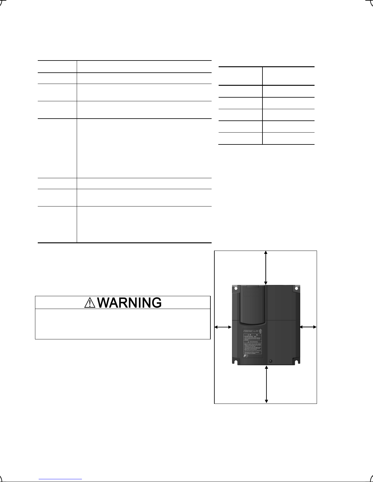
Top 100 mm
Install the inverter on a base constructed from metal or other
non-flammable material.
A fire may result with other material.
(2) Clearances
Ensure that the minimum clearances indicated in Figure 2.1 are
maintained at all times. When installing the inverter in the enclosure
of your system, take extra care with ventilation inside the enclosure
as the temperature around the inverter will tend to increase. Do not
install the inverter in a small enclosure with poor ventilation.
Further,
do not install two or more inverters in single equipment or in
an enclosure.
Right
10 mm
2-1
Left
10 mm
Bottom 100 mm
Figure 2.1 Mounting Direction and
Required Clearances
Page 17
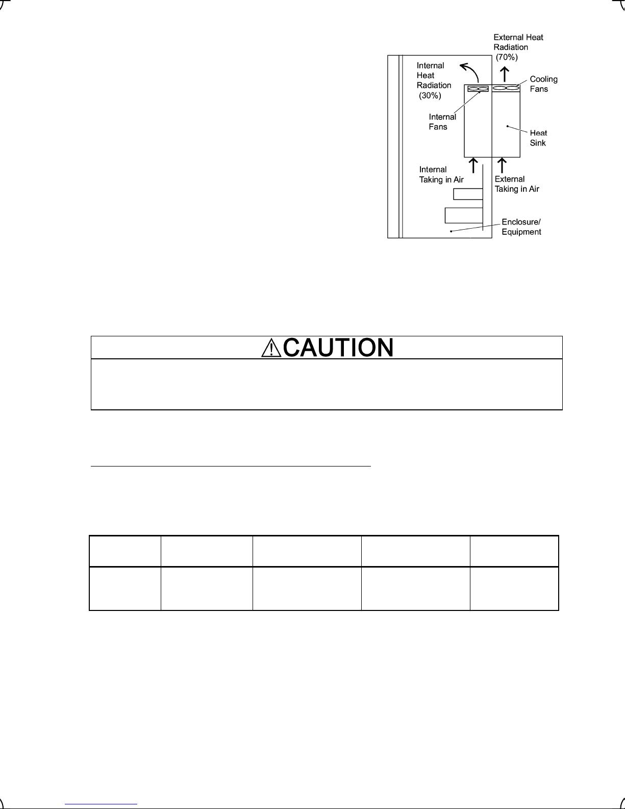
A
When employing external cooling
t the shipment time, the inverter is set up for mount inside your
equipment or enclosure so that cooling is done all internally.
To improve cooling efficiently, you can take the heat sink out of the
equipment or the enclosure (as shown on the right) so that cooling
is done both internally and externally (this is called "external
cooling").
To set up inverters with a capacity of 22 kW or below for "external
cooling," add the optional mounting adapter; to set up ones with a
capacity of 30 kW or above, change the position of the top and
bottom mounting bases as shown below.
For details about the optional mounting adapter, refer to the
Mounting Adapter for External Cooling "PB-F1" Installation
Manual (INR-SI47-0880).
In external cooling, the heat sink, which dissipates about 70% of
the total heat (total loss) generated into air, is situated outside the
equipment or the enclosure. As a result, much less heat is
Figure 2.2 External Cooling
radiated inside the equipment or the enclosure.
In an environment with high humidity or a lot of fibrous dust,
however, do not use external cooling, which tends to clog the heat
sink.
Prevent lint, paper fibers, sawdust, dust, metallic chips, or other foreign materials from getting into the
inverter or from accumulating on the heat sink.
This may result in a fire or accident.
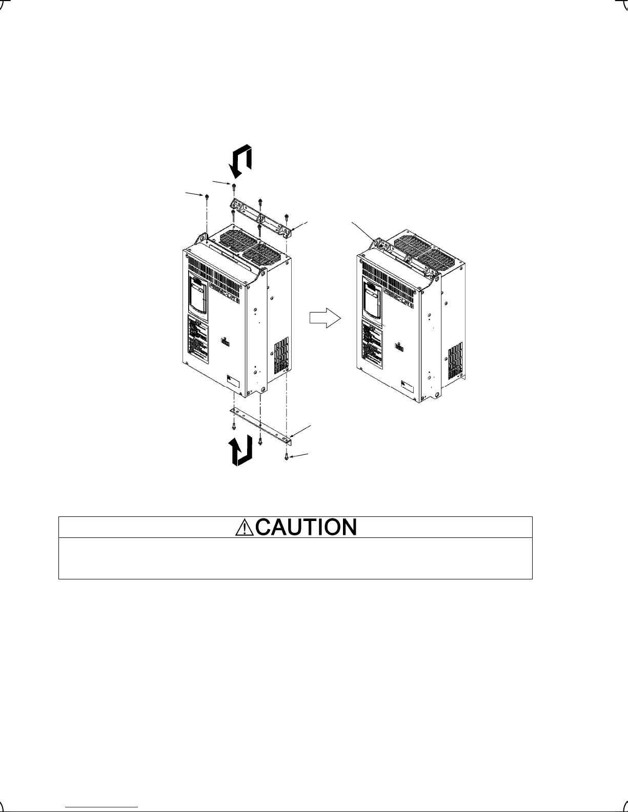
To utilize external cooling for inverters with a capacity of 30 kW
, change the position of the top and bottom
mounting bases from the edge to the center of the inverter as instructed on the next page.
Screws differ in size, length and count for each inverter. Be sure to refer to the table below.
Table 2.3 Screw Count and Tightening Torque
Power supply
voltage
Three-phase
400 V
Note: A box () in the above table replaces C (China), E (EU), A (Asia) or J (Japan) depending on the shipping
destination.
Inverter type
FRN30LM1S-4 to
FRN45LM1S-4
Base fixing screw
(Count)
M6 × 20
(3 pcs each for upper
and lower sides)
2-2
Case fixing screw
(Count)
M6 × 12
(3 pcs for upper side)
Tightening torque
•m)
(N
5.8
Page 18
g
g
1) Remove all of the base fixing screws from the top and bottom of the inverter. Also remove the case fixing
screws from the top. (The case fixing screws are not necessary in external cooling. Store them for future
use. On the bottom are no case fixing screws.)
2) Secure the top mounting base to the center of the inverter with the base fixing screws, using case fixing
screw holes.
3) Secure the bottom mounting base to the center of the inverter with the base fixing screws.
Base fixin
Case fixing screws
screws
Top
mounting
base
Bottom mountin
base
Base fixing screws
Figure 2.3 Relocating the Top and Bottom Mounting Bases
• Please use a specified screw for the change of Bottom mounting base.
Fire or accident could occur.
2-3
Page 19
A
A
(3) Mounting direction
Horizontal layout is recommended when two or more inverters are to be installed in an equipment or enclosure.
As long as the ambient temperature is 40°C or lower, inverters may be mounted side-by-side without any gap
between them. If it is necessary to mount the inverters vertically, install a partition plate or the like between the
inverters so that any heat radiating from an inverter will not affect the one/s above.
Do not mount the inverter upside down or horizontally. Doing so will reduce the heat dissipation
efficiency of the inverter and cause the overheat protection function to operate, so the inverter will not
run.
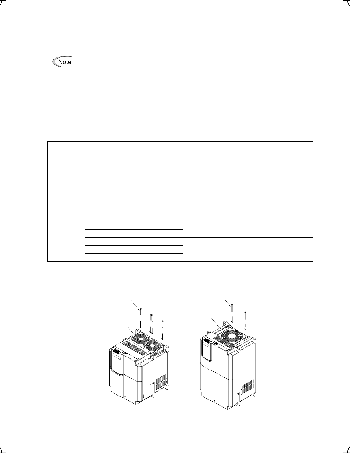
(4) Solving abnormal vibration after installation
If any vibration in the surroundings reaches the inverter and causes abnormal vibration to the cooling fan(s) or
the keypad, fix them firmly using the fixing screws provided as accessories.
Fixing the cooling fan(s)
Table 2.4 Fixing Screws
Power
supply
voltage
Applicable
motor rating
(kW)
Inverter type
Screw size
(accessory)
Tightening
torque
(N·m)
Refer to:
5.5 FRN5.5LM1S-2
Threephase
200 V
7.5 FRN7.5LM1S-2
11 FRN11LM1S-2
15 FRN15LM1S-2
18.5 FRN18.5LM1S-2
M4x35 (4 pcs) 0.8 Figure A
M4x50 (2 pcs) 0.8 Figure B
22 FRN22LM1S-2
5.5 FRN5.5LM1S-4
Threephase
400 V
7.5 FRN7.5LM1S-4
11 FRN11LM1S-4
15 FRN15LM1S-4
18.5 FRN18.5LM1S-4
M4x35 (4 pcs) 0.8 Figure A
M4x50 (2 pcs) 0.8 Figure B
22 FRN22LM1S-4
Note: A box () in the above table replaces C (China), E (EU), A (Asia) or J (Japan) depending on the shipping
destination.
ttached screws
ttached screws
Cooling fans
Figure A Figure B
Cooling fan
Figure 2.4 Fixing the Cooling Fan(s)
2-4
Page 20
2.3 Wiring
Follow the procedure below. (In the following description, the inverter has already been installed.)
2.3.1 Removing and mounting the terminal block (TB) cover and the front cover
(1) For inverter with a capacity of 4.0 kW and Single Phase 2.2kW.
1) First loosen the front cover fixing screw, slide the cover downward holding its both sides, tilt it toward you,
and then pull it upward, as shown below.
2) While pressing the wiring guide upward, pull it out toward you.
3) After carrying out wiring (see Sections 2.3.2 through 2.3.7), put the wiring guide and the front cover back into place
in the reverse order of removal.
Screw
Front cover
Guide
The slide is done forward
while pressing it up.
Figure 2.5 Removing the covers and wiring guide
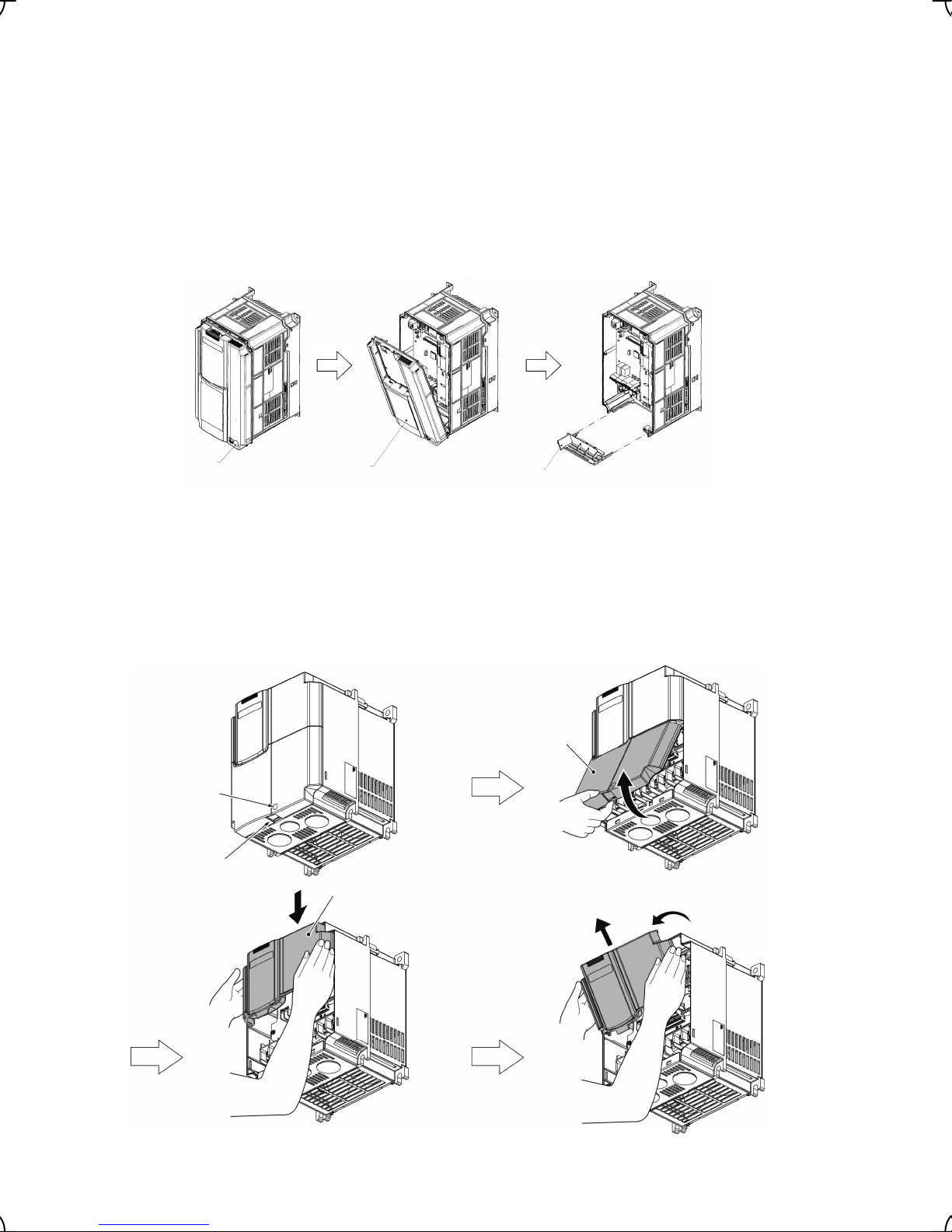
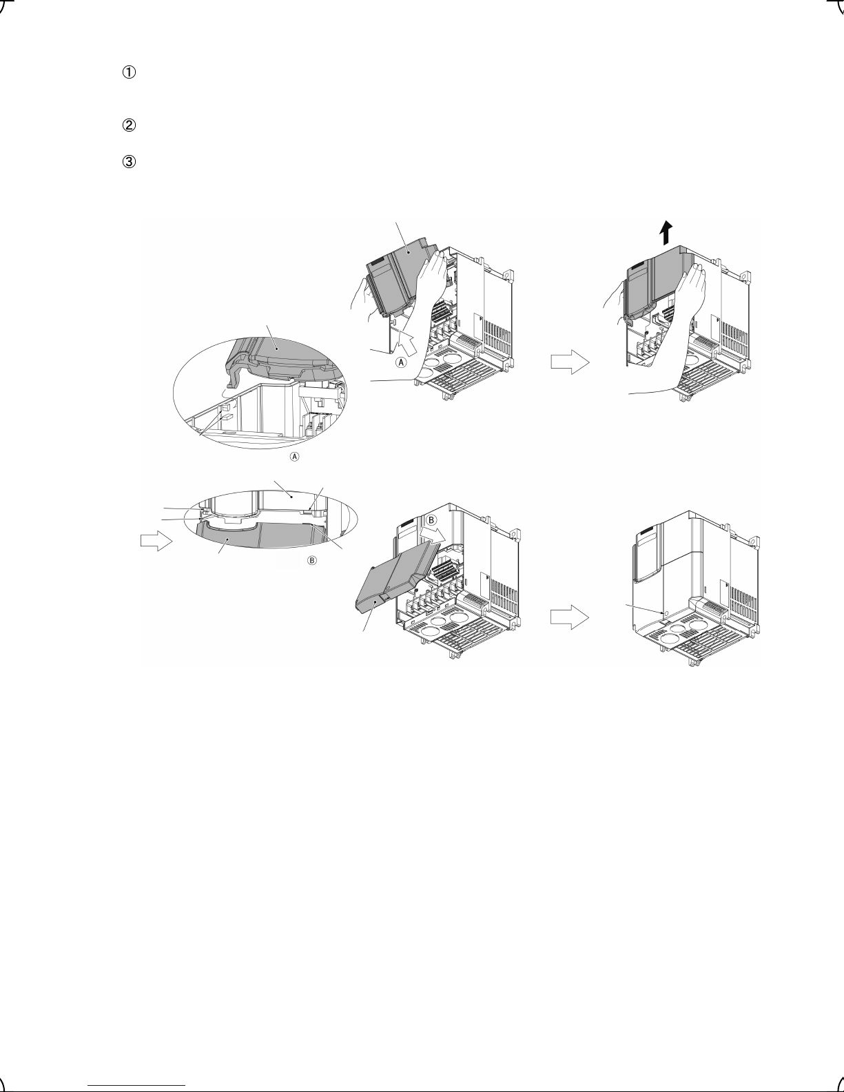
(2) For inverters with a capacity from 5.5 to 22 kW
Removing the covers
1) To remove the TB cover, loosen the fastening screw on it, hold the dimple (labeled “PULL”), and pull it up
toward you.
2) To remove the front cover, hold it with both hands, slide it downward, disengage the latch at the top from
the inverter, tilt the front cover toward you, and pull it upward.
Terminal block
cover
Terminal block
cover fastening
screw
"PULL"
mark
Front cover
Figure 2.6 Removing the Covers
2-5
Page 21
Mounting the covers
Put the front cover to the inverter case so that its bottom engages with the hinges provided on both sides of
the case. Push the front cover against the case of the inverter and slide it upward until the latch at its top
engages with the case.
Mount the TB cover onto the case of the inverter so that the latch at the top of the TB cover engages with a
hole provided at the bottom of the front cover.
Tighten the screw on the TB cover. (Tightening torque: 1.8 N·m)
Front cover
Front cover
Hole
Latch
Hinge
Terminal
block
cover
View from
Front cover
View from
Hole
Latch
Terminal block
cover
Cover
fastening
screw
(terminal
block cover)
Figure 2.7 Mounting the Covers
2-6
Page 22
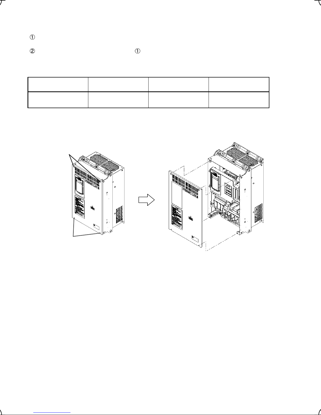
(3) For inverters with a capacity of 30 kW or above
Removing and mounting the cover
To remove the front cover, loosen the four fastening screws, hold it with both hands, and slide it upward.
(Refer to Figure 2.7.)
Put the front cover back in reverse order of . Make sure to properly match the position of the screw holes
on both of the front cover and inverter case.
Table 2.5 Screw Count and Tightening Torque
Power supply voltage Inverter type Front cover screw
Three-phase 400 V
Note: A box () in the above table replaces C (China), E (EU), A (Asia) or J (Japan) depending on the shipping
destination.
FRN30LM1S-4 to
FRN45LM1S-4
M4 x 8 (4 pcs) 1.8
Tightening torque
(N·m)
Fastening screws
Fastening screws
Figure 2.8 Removing and Mounting the Cover (FRN30LM1S-4)
Front cover
2-7
Page 23
A
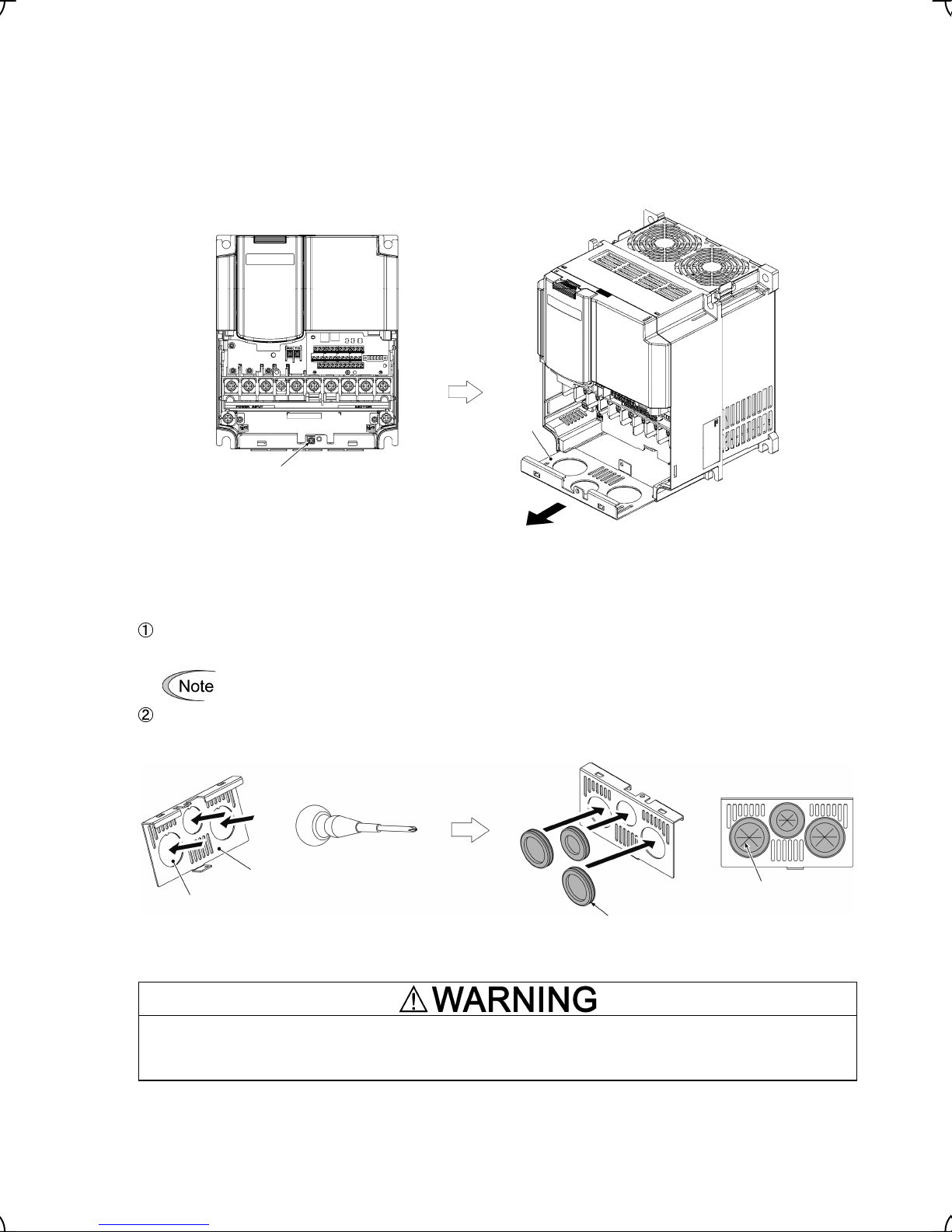
2.3.2 Removing and retracting the cable guide plate
To secure the protective structure IP20, FRENIC-Lift builds in the cable guide plate for external wiring
connections. To use it follow the steps listed below.
Removing the cable guide plate
Before to proceed, remove the terminal block cover as shown below left.
Remove the screw fastening the cable guide plate, and pull out the plate.
Cable
guide
plate
Cable guide plate
fastening screw
Figure 2.9 Removing the Cable Guide Plate
Opening half-punched holes and mounting rubber bushes
Tap an inside face of the half-punched hole by using a screwdriver grip end or the like to punch it out.
Punch out all 3 holes.
Be careful not to injure yourself by sharp cutting edges of parts.
Set 3 attached rubber bushes in the holes and cut in them by a cutting tool to make cut-outs as shown
below. All cables of an inverter should pass through any of cut-outs
Cable guide plate
Cut-outs
Half-punched
holes
Figure 2.10 Punching out the Holes and Mounting the Rubber Bushes
ttached rubber bushes
Be sure to use the rubber bushes. If not, a sharp cutting edge of the cable guide plate hole may damage the cable
sheath. This may induce a short-circuit fault or ground fault.
A fire or an accident may be caused.
Retracting the cable guide plate
Retract the cable guide plate following the steps illustrated in Figure 2.9 in reverse. (Tightening torque: 1.8 N
2-8
•
m)
Page 24

2.3.3 Terminal arrangement and screw specifications
The figures below show the arrangement of the main and control circuit terminals which differs according to
inverter type. The two terminals prepared for grounding, which are indicated by the symbol
G in Figures A to
C, make no distinction between the power supply side (primary circuit) and the motor side (secondary circuit).
(1) Arrangement of the main circuit terminals
Table 2.6 Main Circuit Terminals
Power
supply
voltage
Threephase
200 V
Three-
phase
400 V
Singlephase
200 V
(*1)
Terminal DB on FRN11-LM1S-2/-4: Screw size M5, Tightening torque 3.8 N·m
Terminal R0, T0 (Common to all types): Screw size M3.5, Tightening torque 1.2 N·m
Note: A box (
Applicable
motor rating
(kW)
11 FRN11LM1S-2
15 FRN15LM1S-2
18.5 FRN18.5LM1S-2
22 FRN22LM1S-2
11 FRN11LM1S-4
15 FRN15LM1S-4
18.5 FRN18.5LM1S-4
22 FRN22LM1S-4
30 FRN30 LM1S-4
37 FRN37 LM1S-4
45 FRN45 LM1S-4
) in the above table replaces C (China), E (EU), A (Asia) or J (Japan) depending on the shipping
destination.
Inverter type
5.5 FRN5.5LM1S-2
3.7 FRN4.0LM1S-4
5.5 FRN5.5LM1S-4
M4 1.8 M4 1.8 Figure E
Terminal
screw
size
M5 3.8 M5 3.8
M6
(*1)
M5 3.8 M5 3.8
M6
(*1)
Tightening
torque
(N·m)
5.8
(*1)
5.8
(*1)
Grounding
screw size
M8 13.5 M8 13.5
2.2 FRN2.2LM1S-7 M4 1.8 M4 1.8 Figure F
M6 5.8
M6 5.8
Tightening
torque
(N·m)
Refer to:
Figure A 7.5 FRN7.5LM1S-2
Figure B
Figure A 7.5 FRN7.5LM1S-4
Figure B
Figure C
Figure D
2-9
Page 25
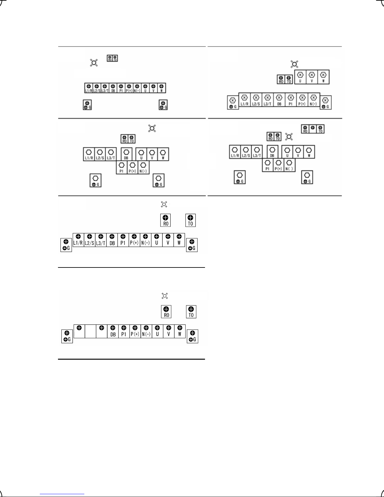
Terminal board illustrated in except Figure A. Take an attention for this structure to connect wires to main output
(secondary) terminals.
Figure A Figure B
Charging Light
Charging Light
Figure C
Figure E
Figure F
Charging Light
Charging Light
Charging Light
Figure D
Charging Light
L1/L
L2/N
2-10
Page 26
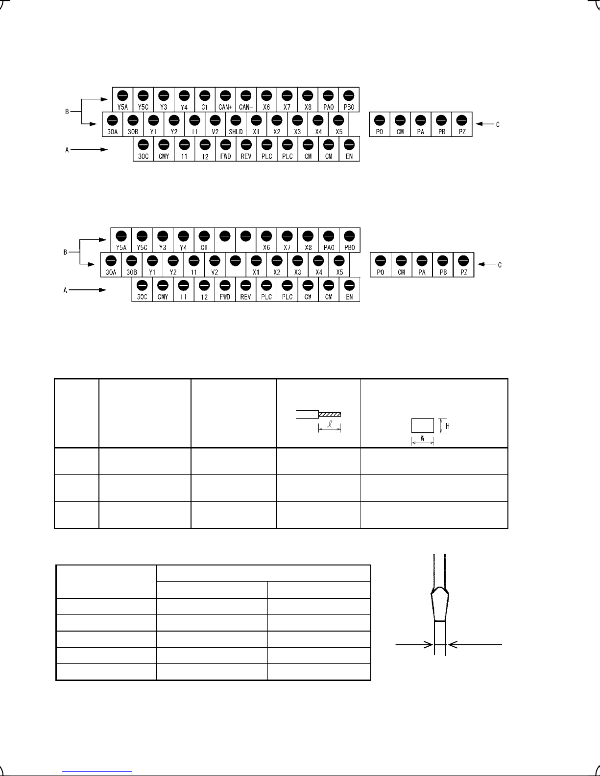
(2) The control circuit terminals (common to all models)
1) For inverters with CAN port (FRN _ _ _ LM1S-2C, -2E, -2A and -2J)
(FRN _ _ _ LM1S-4C, -4E, -4A and -4J)
2) For inverters without CAN port (FRN _ _ _ LM1S-2EA, -2AA and -2JA)
(FRN _ _ _ LM1S-4EA, -4AA and -4JA)
Screw size: M3
Tightening torque: 0.5 to 0.7 (N·m)
Table 2.7 Control Circuit Terminals
Terminal
group
* Manufacturer of ferrules: Phoenix Contact Inc. Refer to Table 2.8.
Screwdriver to be used
(Head style)
A
B
C
Flat head
(0.6 mm x 3.5 mm)
Flat head
(0.6 mm x 3.5 mm)
Flat head
(0.4 mm x 2.5 mm)
Allowable wire size
AWG26 to AWG16
(0.14 to 1.5 mm
AWG26 to AWG16
(0.14 to 1.5 mm
AWG28 to AWG16
(0.08 to 1.5 mm
Table 2.8 Recommended Ferrule Terminals
Type
Screw size
With insulated collar Without insulated collar
Bared wire length
2
)
2
)
2
)
Screw size: M2
Tightening torque: 0.22 to 0.25 (N·m)
Dimension of openings in the
control circuit terminals for ferrule
(for Europe type terminal block)*
6 mm 2.51 mm (W) x 1.76 mm (H)
7 mm 2.75 mm (W) x 2.86 mm (H)
7 mm 1.72 mm (W) x 2.7 mm (H)
AWG24 (0.25 mm2) AI0.25-6BU -
AWG22 (0.34 mm2) AI0.34-6TQ A0.34-7
AWG20 (0.5 mm2) AI0.5-6WH A0.5-6
AWG18 (0.75 mm2) AI0.75-6GY A0.75-6
AWG16 (1.25 mm2) AI1.5-6BK A1.5-7
3.5 mm
Head thickness: 0.6 mm
Screwdriver head style
2-11
Page 27
00
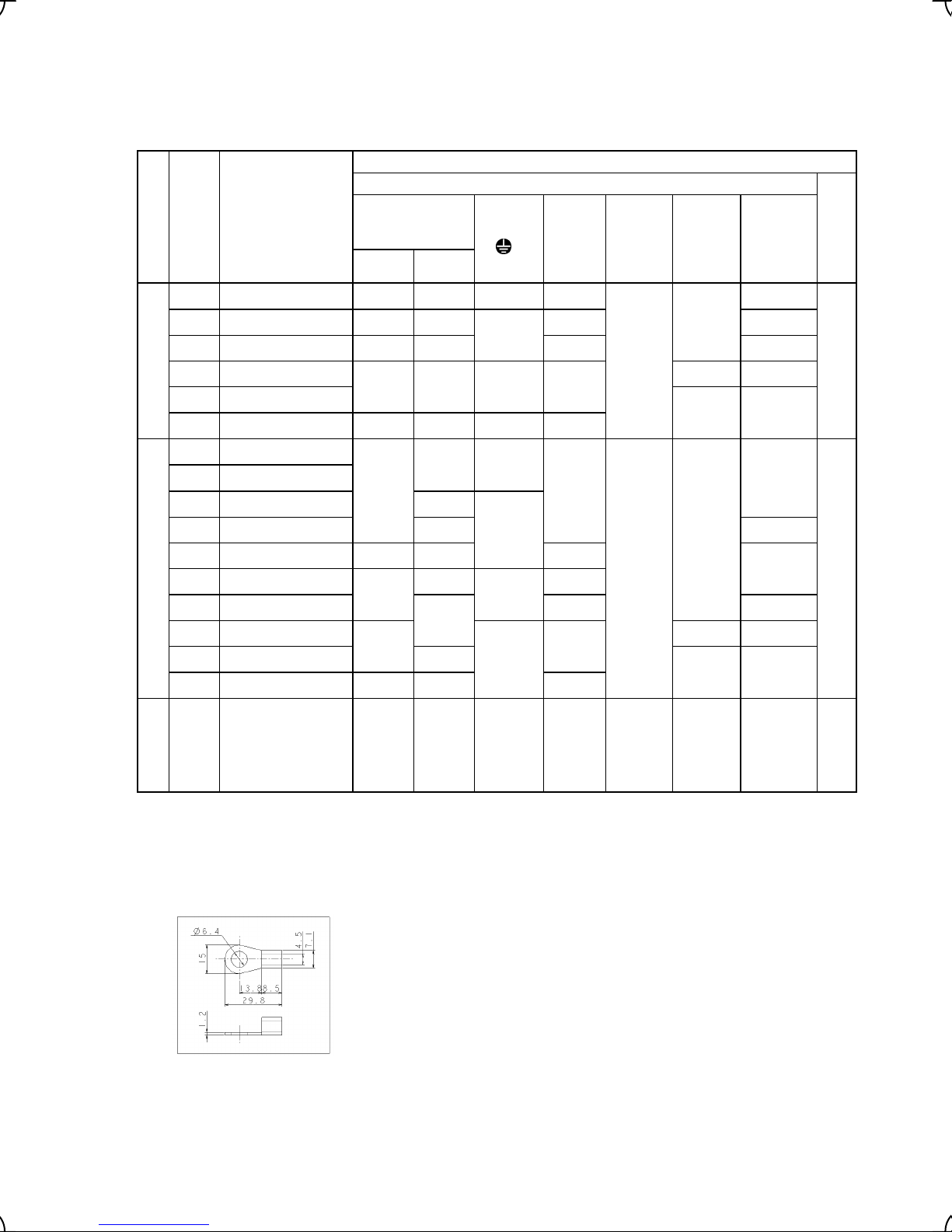
2.3.4 Recommended wire sizes
Table 2.9 lists the recommended wire sizes. The recommended wire sizes for the main circuits are examples of
using HIV single wire (for 75°C) at an ambient temperature of 50°C.
Table 2.9 Recommended Wire Sizes
Recommended wire size (mm2 ) *
G]
Main circuit
Inverter
[U, V, W]
Appli-
cable
motor
rating
voltage
(kW)
Power supply
5.5 FRN5.5LM1S-2 2 3.5 3.5 3.5
7.5 FRN7.5LM1S-2 3.5 5.5
Inverter type
Main circuit power
input
(L1/R, L2/S, L3/T)
w/ DCR w/ DCR
Grounding
[
Auxiliary
Power
output
Input
(Ctrl. cct.)
[R0, T0]
5.5 5.5
1
Braking
resistor
[DB]
2
DCR
[P1, P (+)]
3.5
Control circuit
5.5
11 FRN11LM1S-2 5.5 14 8 8
15 FRN15LM1S-2
2
1.25
3.5 14
14 22 8 14
18.5 FRN18.5LM1S-2
Three-phase 200 V
22 FRN22LM1S-2 22 38 14 22
3.7 FRN4.0LM1S-4
5.5 22
2 2
5.5 FRN5.5LM1S-4
7.5 FRN7.5LM1S-4 2
11 FRN11LM1S-4 3.5 3.5
15 FRN15LM1S-4 3.5 5.5 3.5
18.5 FRN18.5LM1S-4
22 FRN22LM1S-4
Three-phase 400 V
30 FRN30LM1S-4
37 FRN37LM1S-4
2
5.5
14
8
14
22
2
3.5
2
*
5.5
5.5
2
*
8 *2
8
2
2
3.5 14
14
8
2
5.5
1.25
5.5 22
45 FRN45LM1S-4 22
38
22
V
2.2 FRN2.2LM1S-7 2
2
Single-phase
Note: A box () in the above table replaces C (China), E (EU), A (Asia) or J (Japan) depending on the shipping
destination.
*1 Recommended wire sizes are calculated based on the specifications in Chapter 8.
*2 Use the "crimp terminal 8-L6 manufactured by J.S.T. Mfg Co., Ltd." or equivalent. (See the figure below.)
Dimensions of the crimp terminal 8-L6
Use the crimp terminal with an insulation sheath or with processing by the insulation tube. Use the wire of 75°C, 600
V, HIV-insulated. This selection assumes the inverter is used in ambient temperature at 50°C.
3.5
2 2 2 2 2
DCR: DC reactor
1.25
2-12
Page 28
2.3.5 Wiring precautions
Follow the rules below when performing wiring for the inverter.
(1) Make sure that the source voltage is within the rated voltage range specified on the nameplate.
(2) Be sure to connect the three-phase power wires to the main circuit power input terminals L1/R, L2/S and
L3/T of the inverter. If the power wires are connected to other terminals, the inverter will be damaged when
the power is turned on.
(3) Always connect the grounding terminal to prevent electric shock, fire or other disasters and to reduce
electric noise.
(4) Use crimp terminals covered with insulated sleeves for the main circuit terminal wiring to ensure a reliable
connection.
(5) Keep the power supply wiring (primary circuit) and motor wiring (secondary circuit) of the main circuit, and
control circuit wiring as far away as possible from each other.
• When wiring the inverter to the power source, insert a recommended molded case circuit breaker
(MCCB) or earth leakage circuit breaker (ELCB) (with overcurrent protection) in the path of each pair
of power lines to inverters. Use the devices recommended ones within the related current range.
• Use wires in the specified size.
• Tighten terminals with recommended torque.
Otherwise, fire could occur.
• Use a multi-core power cable (3- or 4-wires) to wire the inverter with a motor.
• Do not connect a surge killer to the inverter's output circuit.
Doing so could cause fire.
• According to the input power series install FRENIC-Lift in compliance with local regulations.
Otherwise, electric shock or fire could occur.
• Qualified electricians should carry out wiring.
• Be sure to perform wiring after turning the power off.
Otherwise, electric shock could occur.
• Be sure to perform wiring after installing the inverter.
Otherwise, electric shock or injuries could occur.
• Ensure that the number of input phases and the rated voltage of the product match the number of
phases and the voltage of the AC power supply to which the product is to be connected.
• Do not connect the power source wires to output terminals (U, V, and W).
Doing so could cause fire or an accident.
2.3.6 Wiring for main circuit terminals and grounding terminals
Table 2.10 shows the main circuit power terminals and grounding terminals.
Table 2.10 Symbols, Names and Functions of the Main Circuit Power Terminals
Symbol Name Functions
L1/R, L2/S, L3/T
and L1/L, L2/N
U, V, W Inverter outputs Connect a 3-phase motor.
R0, T0
P1, P(+) DC reactor connection Connect a DC reactor (DCR) for improving power factor.
P(+), N(-) DC link bus Connect an optional regenerative converter or the equivalent.
P(+), DB Braking resistor connection Connect a braking resistor.
G × 2
Main power inputs
Auxiliary power input for
the control circuit
Grounding for inverter and
motor
Connect the 3-phase input power lines or Single-phase input
power lines.
For the models of 200 V series 22 kW or below, and 400 V
series 30 kW or below.
For a backup of the control circuit power supply, connect AC
power lines same as that of the main power input.
For the models of 400 V series 37 kW or above.
For a control circuit, fan and contact a power supply, connect
AC power lines same as that of the main power input.
Grounding terminals for the inverter’s chassis (or case) and
motor. Earth one of the terminals and connect the grounding
terminal of the motor. Inverters provide a pair of grounding
terminals that function equivalently.
2-13
Page 29
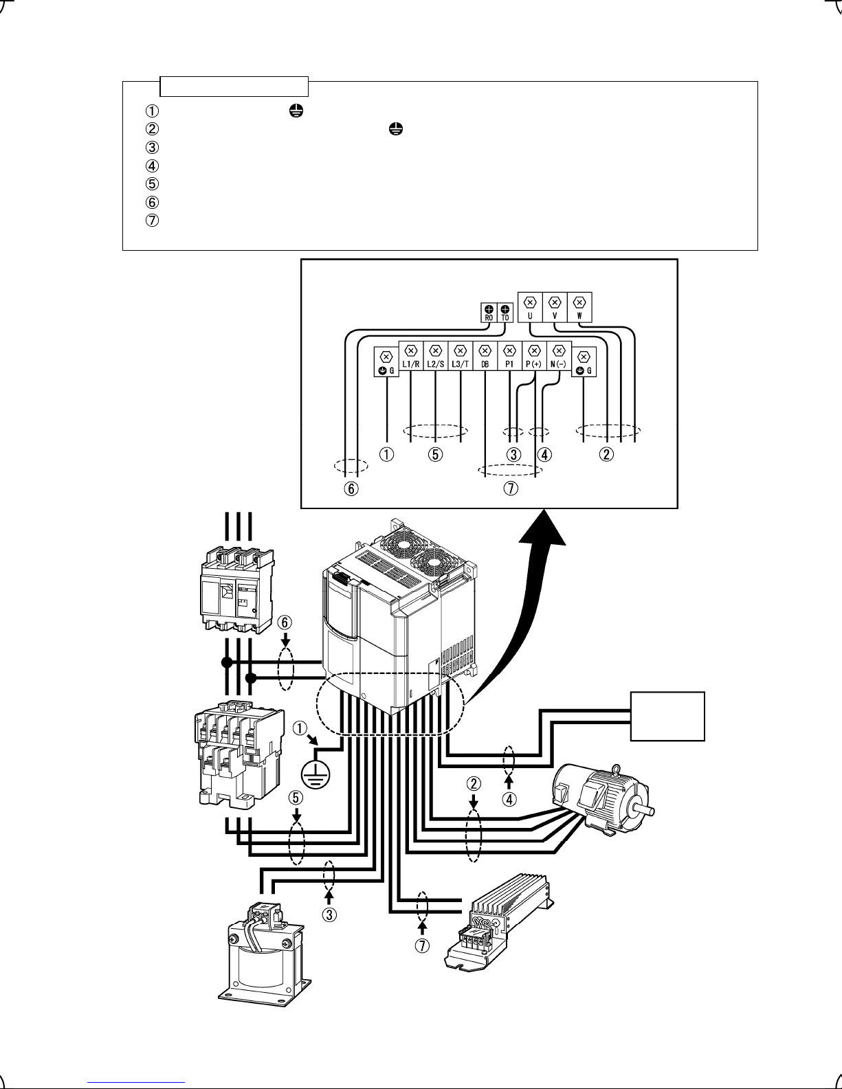
Follow the procedure below for wiring and configuration of the inverter. Figure 2.11 illustrates the wiring
procedure with peripheral equipment.
Wiring procedure
Grounding terminals ( G)
Inverter output terminals (U, V, W, and G)
DC reactor connection terminals (P1 and P(+))*
DC link bus terminals (P(+) and N(-))*
Main circuit power input terminals (L1/R, L2/S and L3/T or L1/L, L2/N)
Auxiliary power input terminals for the control circuit (R0 and T0)*
Braking resistor connection terminals (P(+) and DB)
*
Perform wiring as necessary
Molded
case circuit
breaker
(MCCB) or
earth
leakage
circuit
breaker
(ELCB) with
over current
protection
Magnetic
contactor
Power supply
CAUTION: Do not connect
more than 2 wires to
terminal P(+).
Regenerative
converter
Motor
Braking resistor
DC reactor (DCR)
Figure 2.11 Wiring Procedure for Peripheral Equipment
2-14
Page 30
Grounding terminals ( G)
Be sure to ground either of the two grounding terminals for safety and noise reduction.
Install FRENIC-Lift in compliance with the local regulations, Described below for an example, a procedure
shows an installation of the inverter in compliance with regulations in Japan.
E.g. grounding terminals should be grounded as follows:
1) For the 200 V or 400 V series of inverters, connect the grounding terminal to a ground electrode on which
class D or C grounding work has been completed, respectively, with conformity to the Electric Facility
Technical Standard.
2) Connect a thick grounding wire with a large surface area and which meets the grounding resistance
requirements listed in Table 2.11. Keep the wiring length as short as possible.
Table 2.11 Grounding Stipulated in the Electric Facility Technical Standard
Supply voltage Grounding work class Grounding resistance
Single-phase 200V
Three-phase 200 V
Three-phase 400 V Class C 10 Ω or less
Class D 100 Ω or less
Inverter output terminals, U, V, W and grounding terminals ( G)
Inverter’s output terminals should be connected as follows:
1) Connect the three wires of the 3-phase motor to terminals U, V, and W, aligning phases each other.
2) Connect the secondary grounding wire to the grounding terminal (
• The wiring length between the inverter and motor should not exceed 50 m, when they are
connected directly.
• Do not connect a power factor correcting capacitor or surge absorber to the inverter’s output lines
(secondary circuit).
• If the wiring length is long, the stray capacitance between the wires will increase, resulting in an
outflow of the leakage current. It will activate the overcurrent protection, increase the leakage
current, or will not assure the accuracy of the current display. In the worst case, the inverter could
be damaged.
• Do not drive two or more motors by single inverter.
Driving 400 V series motor
• If a thermal relay is installed in the path between the inverter and the motor to protect the motor
from overheating, the thermal relay may malfunction even with a wiring length shorter than 50 m.
In this situation, lower the carrier frequency (Function code F26: Motor sound (Carrier frequency)).
• When a PWM-type inverter is driving a motor surge voltage that is generated by switching the
inverter component may be superimposed on the inverter output and may be applied to the motor
terminals. Particularly if the wiring length is long, the surge voltage may deteriorate the insulation
resistance of the motor. Consider any of the following measures.
- Use a motor with insulation that withstands the surge voltage.
- Minimize the wiring length between the inverter and motor.
DC reactor terminals, P1 and P (+)
G).
1) Remove the short bar from terminals P1 and P(+).
2) Connect a DC reactor (option) to terminals P1 and P(+).
• The wiring length should be 10 m or below.
• Do not remove the short bar installed across P1 and P(+) terminals if a DC reactor is not to be
used.
2-15
Page 31

DC link bus terminals, P (+) and N (-)
These are provided for the DC link bus powered system. Connect these terminals with terminals P(+) and N (-)
of an optional regenerative converter or the equivalent.
Consult your Fuji Electric representative if these terminals are to be used.
1) For safety, make sure that the molded case circuit breaker (MCCB) or magnetic contactor (MC) is turned off
2) Connect the main circuit power supply wires (L1/R, L2/S and L3/T or L1/L, L2/N (single-phase )) to the input
It is not necessary to align phases of the power supply wires and the input terminals of the inverter with
Main circuit power input terminals, L1/R, L2/S, and L3/T (three-phase input) or L1/L, L2/N
(single-phase input)
before wiring the main circuit power input terminals.
terminals of the inverter via an MCCB or residual-current-operated protective device (RCD)/earth leakage
circuit breaker (ELCB)*, and MC if necessary.
each other.
* With overcurrent protection
It is recommended that a magnetic contactor be inserted that can be manually activated. This is to
allow you to disconnect the inverter from the power supply in an emergency (e.g., when the protective
function is activated) so as to prevent a failure or accident from causing the secondary problems.
Auxiliary power input terminals R0 and T0 for the control circuit
For the models of single-phase 200V, 200V series 22kW or below, and 400V series 30kW or below
In general, the inverter will run normally without power supplied to the auxiliary power input for the control circuit.
However, if you share the input power for the control circuit with that for the main circuit, you would be lost when,
in the event of an error or alarm, you turn OFF the magnetic contactor between the inverter and the commercial
power supply. If the magnetic contactor is turned OFF, the input power to the control circuit is shut OFF, causing
the alarm signals (30A/B/C) to be lost and the display on the keypad to disappear. To secure input power to the
control circuit at all times, supply the power from the primary side of the magnetic contactor to control power
auxiliary input terminals R0 and T0. The method of connecting auxiliary power input terminals for the control
circuit refer to Section 2.3.8 "Setting up slide switches."
For the models of 400 V series 37 kW or above
The inverter will not run normally without power supplied to the auxiliary power input for the control circuit.
However, if you share the input power for the control circuit with that for the main circuit, you would be lost when,
in the event of an error or alarm, you turn OFF the magnetic contactor between the inverter and the commercial
power supply. If the magnetic contactor is turned OFF, the input power to the control circuit is shut OFF, causing
the alarm signals (30A/B/C) to be lost and the display on the keypad to disappear. To secure input power to the
control circuit at all times, supply the power from the primary side of the magnetic contactor to control power
auxiliary input terminals R0 and T0. The method of connecting auxiliary power input terminals for the control
circuit refer to Section 2.3.8 "Setting up slide switches."
When the DC power input is used, auxiliary power input terminals is used. The connected AC power is:
Single phase 380 to 460 V/50 Hz or 60 Hz for 400 V series 37 kW or above
Note: Allowable power input voltage range should be within – 15% to +10% of power source voltage.
Connect the power supply with R0 and T0 if the inverter of 37 kW or above is used, and the main
power supply is connected.
If you do not connect the power supply with Auxiliary power input terminals, the cooling fan will not run,
causing a heat sink overheating alarm "
0h1
" or a charger circuit error alarm "
2-16
pbf
."
Page 32
Braking resistor connection terminals, P(+) and DB
1) Connect terminals P and DB of an external braking resistor to terminals P(+) and DB on the main circuit
terminal block. (For the braking resistor built-in type, refer to the next page.)
2) When using an external braking resistor, arrange the inverter and braking resistor to keep the wiring length
to 5 m or less and twist the two wires or route them together in parallel.
Never insert a braking resistor between terminals P(+) and N(-), P1 and N(-), P(+) and P1, DB and N(-), or
P1 and DB.
Doing so could cause fire.
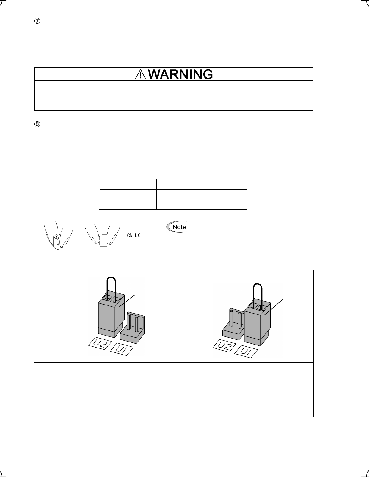
Power switching connectors [CN UX] (for the models of 400 V series 37 kW or above)
An inverter of 400 V series 37 kW or above is equipped with a set of switching connectors CN UX (male) which
should be configured with a jumper according to the power source voltage and frequency. Set the jumper to U1
or U2 depending upon the power source voltage applied to the auxiliary power input terminals (R0, T0), as
shown in Figure 2.13. Power switching connectors [CN UX] is arranged in the power supply printed wiring board
in the right part of the control printed wiring board. Please refer to figure 2.12 and Figure 2.13 for details.
Table 2.12 Voltage in which connection of Power switching connectors is changed
Frequency (Hz) Power supply voltage(V)
50 420~480
60 430~480
Figure 2.12 Inserting/Removing the Jumpers
Setting
380 to 420 V/50 Hz
380 to 430 V/60 Hz
CN UX (red)
To remove the jumper, pinch its upper side
between your fingers, unlock its fastener and pull
it up. To insert it, pull it down as firmly as it locks
with the connector until you will have heard a
click sound.
CN UX (red)
420 to 480 V/50 Hz
430 to 480 V/60 Hz
(
Factory default)
Volta ge
Note: Allowable power input voltage range should be
within – 15% to +10% of power source voltage.
Figure 2.13 Setting up the power switching connector [CN UX].
Note: Allowable power input voltage range should be
2-17
within – 15% to +10% of power source voltage.
Page 33

2.3.7 Wiring for control circuit terminals
In general, sheaths and covers of the control signal cables and wires are not specifically designed to
withstand a high electric field (i.e., reinforced insulation is not applied). Therefore, if a control signal cable or
wire comes into direct contact with a live conductor of the main circuit, the insulation of the sheath or the
cover might break down, which would expose the signal wire to a high voltage of the main circuit. Make sure
that the control signal cables and wires will not come into contact with live conductors of the main circuit.
Failure to observe these precautions could cause electric shock and/or an accident.
Noise may be emitted from the inverter, motor and wires.
Implement appropriate measure to prevent the nearby sensors and devices from malfunctioning due to such
noise.
An accident could occur.
Table 2.13 lists the symbols, names and functions of the control circuit terminals. The wiring to the control circuit
terminals differs depending upon the setting of the function codes, which reflects the use of the inverter.
2-18
Page 34

Table 2.13 Symbols, Names and Functions of the Control Circuit Terminals
Symbol Name Functions
cation
Classifi-
[12] Voltage
input
[C1] Current
input
[V2] Voltage
input
Analog input
(1) The reference speed (frequency) follows the input voltage level on terminal [12].
- 0 to ±10 VDC/0 to ±100 (%)
- Definition of 100%: Maximum speed (F03)
(2) The reference torque bias follows the input voltage level on terminal [12].
- 0 to ±10 VDC/0 to ±100 (%)
- Definition of the 100% torque bias: Rated output torque of the motor
(3) The reference torque current follows the input voltage level on terminal [12].
- 0 to ±10 VDC/0 to ±100 (%)
- Definition of 100% torque current: Rated overcurrent of the inverter
(1) The reference speed (frequency) follows the input current level on terminal [C1].
- +4 to +20 mA DC/0 to 100 (%)
- Definition of 100%: Maximum speed (F03)
(2) The reference torque bias follows the input current level on terminal [C1].
- +4 to +20 mA DC/0 to 100 (%)
- Definition of the 100% torque bias: Rated output torque of the motor
(3) The reference torque current follows the input current level on terminal [C1].
- +4 to +20 mA DC/0 to 100 (%)
- Definition of 100% torque current: Rated overcurrent of the inverter
* Input impedance: 250 Ω
* Allowable input current is +30 mA DC. If the input current exceeds +20 mA DC, the
inverter will limit it at +20 mA DC.
(1) The reference speed (frequency) follows the input voltage level on terminal [V2].
- 0 to ±10 VDC/0 to ±100 (%)
- Definition of 100%: Maximum speed (F03)
(2) The reference torque bias follows the input voltage level on terminal [V2].
- 0 to ±10 VDC/0 to ±100 (%)
- Definition of the 100% torque bias: Rated output torque of the motor
(3) The reference torque current follows the input voltage level on terminal [V2].
- 0 to ±10 VDC/0 to ±100 (%)
- Definition of 100% torque current: Rated overcurrent of the inverter
(4) This terminal is also used to connect a PTC (Positive Temperature Coefficient)
thermistor to protect the motor from an overheat failure. To do so, switch SW4 on the
control PCB to PTC side.
Figure shown at the right illustrates the
internal circuit diagram where the slide
switch SW4 (switching the input of
terminal [V2] between V2 and PTC)
selects PTC. For details of SW4 refer
to Section 2.3.8 “Setting up slide
switches.” In this case, you must
change data of the function code H26.
* Input impedance: 22 kΩ
* Allowable input voltage is +15 VDC. If the input voltage exceeds +10 VDC,
however, the inverter will limit it at +10 VDC.
Figure 2.14 Internal Circuit Diagram (SW4 Selecting PTC)
2-19
Page 35
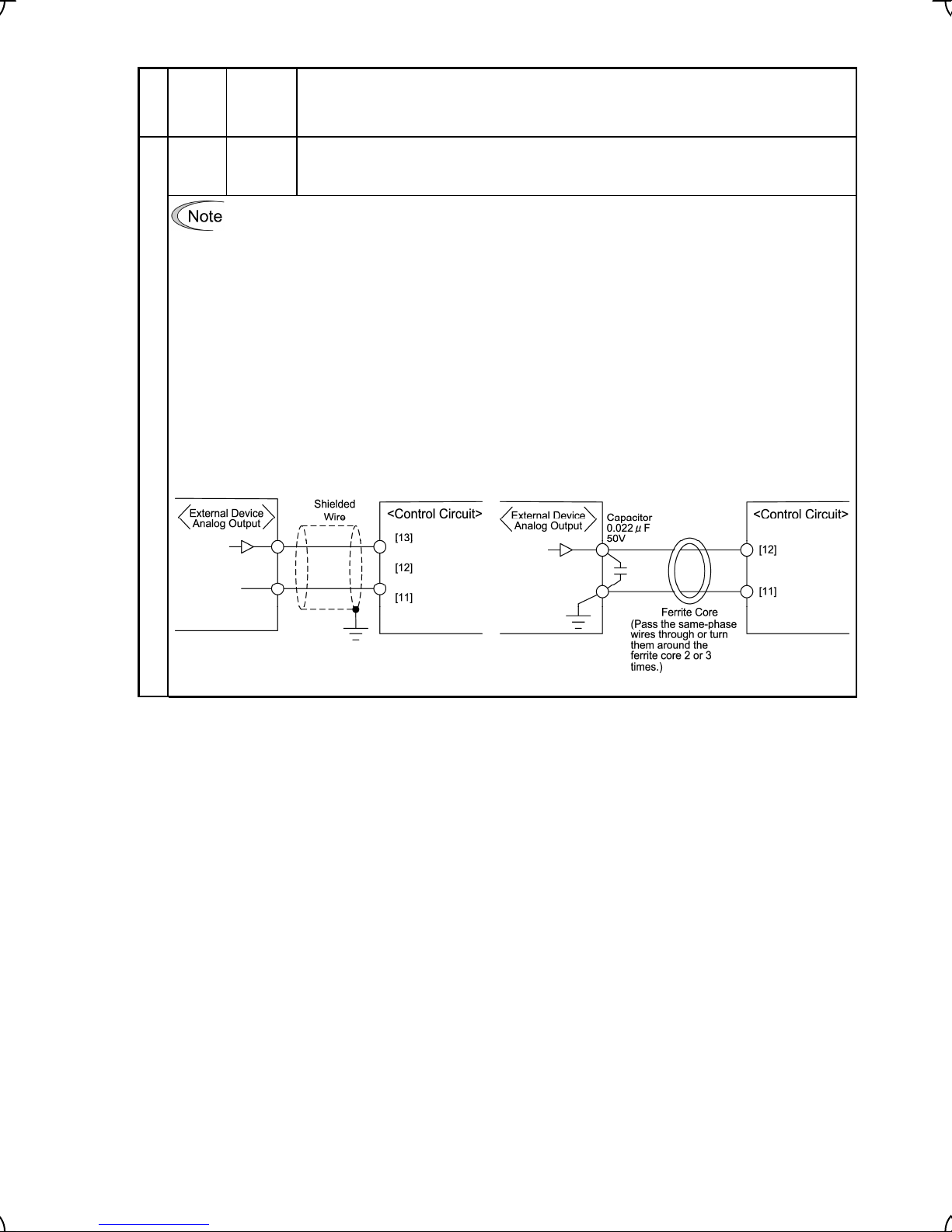
Table 2.13 Continued
Symbol Name Functions
Classifi-
cation
[11]
(Two
terminals)
Analog
common
Two common terminals for analog input and output signal terminals [12], [C1], and [V2].
These terminal are electrically isolated from terminals [CM]s and [CMY].
- Since low level analog signals are handled, these signals are especially susceptible to the external
noise effects. Route the wiring as short as possible (within 20 m) and use shielded wires. In
principle, ground the shielding layer of the shielded wires; if effects of external inductive noises are
considerable, connection to terminal [11] may be effective. As shown in Figure 2.15, ground the
single end of the shield to enhance the shielding effect.
- Use a twin contact relay for low level signals if the relay is used in the control circuit. Do not connect
the relay's contact to terminal [11].
- When the inverter is connected to an external device outputting the analog signal, a malfunction
may be caused by electric noise generated by the inverter. If this happens, according to the
circumstances, connect a ferrite core (a toroidal core or an equivalent) to the device outputting the
analog signal and/or connect a capacitor having the good cut-off characteristics for high frequency
components between control signal wires as shown in Figure 2.16.
Analog input
- Do not apply a voltage of +7.5 VDC or higher to terminal [C1]. Doing so could damage the internal
control circuit.
Figure 2.15 Connection of Shielded Wire Figure 2.16 Example of Electric Noise Reduction
2-20
Page 36

Table 2.13 Continued
Symbol Name Functions
Classifi-
cation
[X1] Digital
input 1
[X2] Digital
input 2
[X3] Digital
input 3
[X4] Digital
input 4
[X5] Digital
(1) The various signals such as coast-to-stop, alarm from external equipment, and
multistep speed commands can be assigned to terminals [X1] to [X8], [FWD], [REV],
and [EN] by setting function codes E01 to E08, E98, and E99. For details, refer to
Chapter 5, Section 5.2 "Overview of Function Codes."
(2) Input mode, i.e. Sink/Source, is changeable by using the internal slide switch SW1.
(3) Switches the logic value (1/0) for ON/OFF of the terminals between [X1] to [X8],
[FWD], [REV], or [EN] and [CM]. If the logic value for ON between [X1] and [CM] is 1
in the normal logic system, for example, OFF is 1 in the negative logic system and vice
versa.
(4) The negative logic signaling cannot be applicable to some signals such as [FWD] and
[REV].
input 5
[X6] Digital
(Digital input circuit specifications)
input 6
[X7] Digital
input 7
Operation
voltage
(SINK)
Item Min. Max.
ON level
0 V 2 V
OFF level 21 V 27 V
[X8] Digital
input 9
[FWD] Run
forward
command
[REV] Run
reverse
command
Operation
voltage
(SOURCE)
Operation current at ON
(Input voltage is at 0V)
Allowable leakage
current at OFF
ON level
OFF level
21 V 27 V
0 V 2 V
2.5 mA 5 mA
- 0.5 mA
Figure 2.17 Digital Input Circuit
Digital input
[EN] Enable If this terminal signal turns off, the inverter shut its power output down to absolutely stop
operation of the inverter.
[PLC]
(Two
terminals)
[CM]
(Two
terminals)
PLC
signal
power
Digital
common
Connects to PLC output signal power supply.
(Rated voltage: +24 VDC: Allowable range: +22 to +27 VDC)
Common terminals for digital input signal terminals
These terminals are electrically isolated from the terminals, [11]s and [CMY].
Figure 2.18 Digital Input Circuit
2-21
Page 37

Table 2.13 Continued
Symbol Name Functions
Classifi-
cation
Turning on or off [X1] to [X8], [FWD], [REV], or [EN] using a relay contact
Figure 2.19 shows two examples of a circuit that turns on or off control signal input [X1] to [X8],
[FWD], [REV], or [EN] using a relay contact. In the circuit (a), the slide switch SW1 has been turned
to SINK, whereas in the circuit (b) it has been turned to SOURCE.
NOTE: To configure this kind of circuit, use a highly reliable relay
(Recommended product: Fuji control relay Model HH54PW.)
(a) With the switch turned to SINK
(b) With the switch turned to SOURCE
Figure 2.19 Circuit Configuration Using a Relay Contact
Turning on or off [X1] to [X8], [FWD], [REV], or [EN] using a programmable logic controller
(PLC)
Figure 2.20 shows two examples of a circuit that turns on or off control signal input [X1] to [X8], [FWD],
Digital input
[REV], or [EN] using a programmable logic controller (PLC). In the circuit (a), the switch SW1 has been
turned to SINK, whereas in the circuit (b) it has been turned to SOURCE.
In circuit (a) below, short-circuiting or opening the transistor's open collector circuit in the PLC using an
external power source turns on or off control signal [X1] to [X8], [FWD], [REV], or [EN]. When using this
type of circuit, observe the following:
- Connect the + node of the external power source (which should be isolated from the PLC's power)
to terminal [PLC] of the inverter.
- Do not connect terminal [CM] of the inverter to the common terminal of the PLC.
(a) With the switch turned to SINK
For details about the slide switch setting, refer to Section 2.3.8 “Setting up slide switches.”
(b) With the switch turned to SOURCE
Figure 2.20 Circuit Configuration Using a PLC
2-22
Page 38

Table 2.13 Continued
Symbol Name Functions
Classifi-
cation
[Y1] Transistor
output 1
(1) Various signals such as inverter running, speed/freq. arrival and overload early
warning can be assigned to the terminal [Y1] by setting function code E20 to E23.
Refer to Chapter 5, Section 5.2 "Overview of Function Codes" for details.
(2) Switches the logic value (1/0) for ON/OFF of the terminals between [Y1] to [Y4] and
[CMY]. If the logic value for ON between [Y1] to [Y4] and [CMY] is 1 in the normal
logic system, for example, OFF is 1 in the negative logic system and vice versa.
Transistor output circuit specification
[Y2] Transistor
output 2
Item
Max.
[Y3] Transistor
output 3
[Y4] Transistor
output 4
Transistor output
[CMY] Transistor
output
common
Connecting Programmable Controller (PLC) to Terminal [Y1], [Y2], [Y3], or [Y4]
Figure 2.22 shows two examples of circuit connection between the transistor output of the inverter’s
control circuit and a PLC. In the example (a), the input circuit of the PLC serves as the sink for the
control circuit output, whereas in the example (b), it serves as the source for the output.
Operation
voltage
Maximum load current
at ON
Leakage current at OFF
ON level
OFF level
27 V
50 mA
0.1 mA
Figure 2.21 Transistor Output Circuit
Figure 2.21 shows examples of connection between the control circuit and a PLC.
- Check the polarity of the external power inputs.
- When connecting a control relay, connect a surge-absorbing diode across the
coil of the relay.
- When any equipment or device connected to the transistor output needs to be
supplied with DC power, feed the power (+24 VDC: allowable range: +22 to +27
VDC, 50 mA max.) through the [PLC] terminal. Short-circuit between the
terminals [CMY] and [CM] in this case.
Common terminal for transistor output signal terminals
This terminal is electrically isolated from terminals, [CM]s and [11]s.
3 V
(a) PLC serving as Sink (b) PLC serving as Source
Figure 2.22 Connecting PLC to Control Circuit
2-23
Page 39
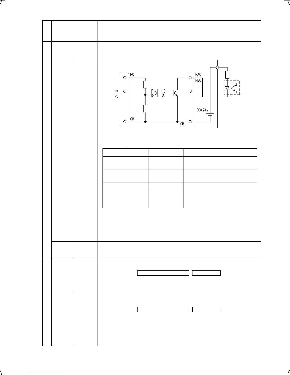
Table 2.13 Continued
Symbol Name Functions
Classifi-
cation
[PAO] A-phase
pulse output
[PBO] B-phase
pulse output
These terminals output the inputs PA and PB from the pulse encoder head-to-head in
a pair of open collector outputs
Pulse encoder outputs
[CM](Two
terminals)
[Y5A/C] General
Digital
common
purpose
relay output
Figure 2.23 Output Circuits for the Pulse Encoder (a pair of PA/PB)
Specifications
Terminal voltage +27 VDC max.
Terminal current 50mA max.
Frequency response 25 kHz min.
Wire length Less than 20m
Note Length of the wire may affect distortion of the waveform of terminal output
Common terminals for digital input signals.
These terminals are electrically isolated from terminals [11] and [CM]
(1) A general-purpose relay contact output usable as well as the function of the
transistor output terminal [Y1], [Y2], [Y3], or [Y4].
Contact rating: 250 VAC 0.3 A, cos φ = 0.3 , 48 VDC, 0.5 A
(2) You can switch its output mode between “Active ON” (the terminals [Y5A] and
[Y5C] are short-circuited if the signal is active.)” and “Active OFF” (the terminals
[Y5A] and [Y5C] are open-circuited if the signal is active.).
Item Specifications Remarks
Measured between terminals PA0 or
PB0 and CM.
Sink current of terminals PA0 and
PB0
Wire length between terminals
PA0/PB0 and terminals on external
equipment
signals.
The lower resistance in a circuit the larger current flow there. Choose a
pull-up resistor with lower resistance as possible within the allowable
current limit 50 mA for a stable operation.
[30A/B/C] Alarm relay
output
(for any
error)
Relay contact output
(1) Outputs a contact signal (SPDT) when a protective function has been activated to
stop the motor.
Contact rating: 250 VAC, 0.3A, cos φ = 0.3 , 48 VDC, 0.5A
(2) A command similar to terminals [Y1] to [Y4] can be assigned for this relay contact
and use it for signal output.
(3) Switching of the normal/negative logic output is applicable to the following two
contact outputs: "Terminals [30A] and [30C] are short-circuited for ON signal
output (Active ON)" or "the terminals [30B] and [30C] are short-circuited
(non-excited) for ON signal output (Active OFF)."
2-24
Page 40
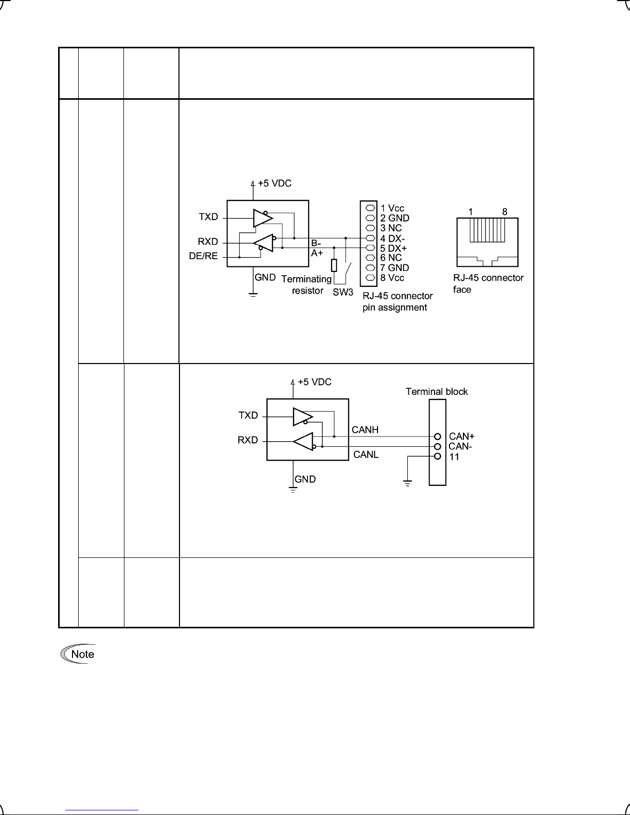
Table 2.13 Continued
Symbol Name Functions
cation
Classifi-
RJ-45
connector
for the
keypad
[CAN+]
[CAN-]
Communication
Standard
RJ-45
connector
CAN
Communications link
input
terminals
(1) Used to connect the inverter with PC or PLC using RS485 port. The inverter
supplies the power to the keypad through the extension cable for keypad.
(2) Remove the keypad from the standard RJ-45 connector, and connect the RS485
communications cable to control the inverter through the PC or PLC
(Programmable Logic Controller). Refer to Section 2.3.8 for setting of the
terminating resistor.
Figure 2.24 RJ-45 Connector and its Pin Assignment*
* Do not use the pins 1, 2, 7, and 8 for using this connector to connect other
equipment since these pins are assigned for power lines for the keypad.
[SHLD] Connecting
shield
sheath of
communications
cable
-
Route the wiring of the control terminals as far from the wiring of the main circuit as possible.
Otherwise electric noise may cause malfunctions.
Fix the control circuit wires inside the inverter to keep them away from the live parts of the main
-
circuit (such as the terminal block of the main circuit).
Figure 2.25 CAN Communications Interface Circuit
Use terminal [11] for the grounding terminal of CAN.
These terminals are provided on inverters with CAN port (FRN _ _ _ LM1S-C, -E,
-A and -J).
Use this terminal to connect the shielded sheath of the CAN communications cable.
This terminal is not electrically connected to internal circuits of the inverter.
These terminals are provided on inverters with CAN port (FRN _ _ _ LM1S-C, -E,
-A and -J).
2-25
Page 41

Table 2.13 Continued
Symbol Name Functions
cation
Classifi-
[PO] Power
[PA] Pulse
[PB] Pulse
[PZ] Pulse
Pulse encoder
[CM] Pulse
terminal for
the pulse
encoder
encoder
input A
encoder
input B
encoder
input Z
encoder
common
terminal
-
Route the wiring of the control terminals as far from the wiring of the main circuit as possible.
Otherwise electric noise may cause malfunctions.
Secure the control circuit wires the inside wall of the inverter to keep them away from the live parts
-
of the main circuit (such as the terminal block of the main circuit).
Use this terminal to supply a power to the pulse encoder mounted outside the
inverter.
Switching the slide switch SW5 switches its output voltage between 15 VDC and 12
VDC.
Specifications
15V: 15 VDC ±10%, 120 mA
12V: 12 VDC ±10%, 120 mA
Specifications
Pulse encoder
output system
Allowable input
pulse frequency
(rate)
Wiring length 20 m or less
Located on the encoder terminal block is the common (grounding) terminal for the
pulse encoder.
Figure 2.26 Pulse Encoder Input Circuits
Item Specifications
Open collector Complementary
25 kHz max. 100 kHz max.
2-26
Page 42

2.3.8 Setting up slide switches
Before setting up any internal control switches, turn the power OFF. For the inverters with a capacity of 22
kW or below, wait at least 5 minutes; for the inverters with a capacity of 30 kW or above, wait at least 10
minutes. Further, check that the charge lamp is unlit, and make sure that the DC link bus voltage between
the terminals P(+) and N(-) has dropped below a safe voltage (+25 VDC) using a multimeter or a similar
instrument.
An electric shock may result if this warning is not heeded as there may be some residual electric
charge in the DC link bus capacitor even after the power has been turned off.
Setting up the slide switches
To switch the slide switches, remove the front and terminal block covers, so that you can access the control
PCB that contains the switches.
For details of removing the front cover, terminal block cover, and dummy cover, refer to Section 2.3.1
“Removing and mounting the terminal block (TB) cover and the front cover.”
Table 2.14 lists function of each slide switch.
Table 2.14 Function of Each Slide Switch
Switch Function
SW1 Switches service mode of the digital input terminals for SINK or SOURCE.
▪ To make the digital input terminal [X1] to [X8], [FWD], [REV], or [EN] serve as a current sink,
switch SW1 to SINK. (Factory defaults on inverters destined for China, Asia and Japan)
▪ To make them serve as a current source, to SOURCE. (Factory defaults on inverters destined
for the EU)
SW3 Switches on/off the terminating resistor of RS485 communications port of the inverter.
▪ To connect a keypad to the inverter switch SW3 to OFF (Factory defaults.)
▪ If the inverter is connected to the RS485 communications network as a termination device,
switch it to ON.
SW4 Switches property of the analog input terminal V2 for V2 or PTC.
When switching this switch, change data of the function code H26.
Switch SW4 to: Set data of H26 to:
Analog speed command source in
voltage
(Factory defaults)
SW5 Switches the voltage of the power source to the pulse encoder between 12 VDC and 15 VDC
(Factory defaults: 12 VDC.)
PTC thermistor input PTC 1 or 2
V2 0
2-27
Page 43

V
Figure 2.27 shows location of the configuration slide switches.
Switching example
SW3
OFF
ON
SW1
SINK
SINK SOURCE
V2
PT
SW4
SINK
SOURCE
SW1
12
15V
SW5
SOURCE
Control circuit terminal block
Figure 2.27 Location of the Slide Switches
2.4 Cautions Relating to Harmonic Component, Noise, and Leakage Current
(1) Harmonic component
Input current to an inverter includes harmonic components, which may affect other loads and power factor
correcting capacitors that are connected to the same power source as the inverter. If harmonic components
cause any problems, connect a DC reactor (option) to the inverter. It may also be necessary to connect an AC
reactor serially to the power factor correcting capacitors.
(2) Noise
If noise generated from the inverter affects other devices, or that generated from peripheral equipment causes
the inverter to malfunction, follow the basic measures outlined below.
1) If noise generated from the inverter affects the other devices through power wires or grounding wires:
- Isolate the grounded metal frames of the inverter from those of the other devices.
- Connect a noise filter to the inverter power wires.
- Isolate the power system of the other devices from that of the inverter with an insulated transformer.
2) If induction or radio noise generated from the inverter affects other devices through power wires or
grounding wires:
- Isolate the main circuit wires from the control circuit wires and other device wires.
- Put the main circuit wires through a metal conduit and connect the pipe to the ground near the inverter.
- Install the inverter onto the metal switchboard and connect the whole board to the ground.
- Connect a noise filter to the inverter power wires.
3) When implementing measures against noise generated from peripheral equipment:
- For the control signal wires, use twisted or shielded-twisted wires. When using shielded-twisted wires,
connect the wire sheath shield to the common terminals of the control circuit or ground.
- Connect a surge absorber in parallel with a coil or solenoid of the magnetic contactor.
2-28
Page 44

(3) Leakage current
Harmonic component current generated by insulated gate bipolar transistors (IGBTs) switching on/off inside the
inverter becomes leakage current through stray capacitors of inverter input and output wires or a motor. If any of
the problems listed below occur, take an appropriate measure against them.
Table 2.15 Leakage Current Countermeasures
Problem Measures
An earth leakage circuit
breaker* that is connected to
the input (primary) has tripped.
* With overcurrent protection
An external thermal relay was
activated.
1) Decrease the carrier frequency.
2) Make the wires between the inverter and motor shorter.
3) Use an earth leakage circuit breaker that has a longer sensitive current than
one currently being used.
4) Use an earth leakage circuit breaker that features measures against
harmonic component (Fuji SG and EG series).
1) Decrease the carrier frequency.
2) Increase the settling current of the thermal relay.
3) Use the electronic thermal motor overheat protection built in the inverter,
instead of an external thermal relay.
2-29
Page 45

Chapter 3 OPERATION USING THE KEYPAD
The FRENIC-Lift has no standard keypad. Using the optional multi-function keypad allows you to start and stop
the motor, monitor running status, and switch to the menu mode. You may also set the function code data, monitor
I/O signal states, maintenance information, and alarm information.
For details of the multi-function keypad, refer to the Multi-function Keypad "TP-G1-CLS" Instruction Manual
(INR-S147-1092-E).
3-1
Page 46

Chapter 4 RUNNING THE MOTOR
4.1 Running the Motor for a Test
4.1.1 Inspection and preparation prior to powering on
(1) Check if connection is correct.
Especially check if the power wires are connected to the inverter input terminals L1/R, L2/S and L3/T or L1/L, L2/N,
and output terminals U, V and W respectively and that the grounding wires are connected to the ground electrodes
correctly. Note that FRENIC-Lift series is designed for three phase input and driving three phase motors.
• Do not connect power supply wires to the inverter output terminals U, V, and W. Otherwise, the inverter may be
broken if you turn the power ON.
• Be sure to connect the grounding wires of the inverter and the motor to the ground electrodes.
Otherwise, electric shock may occur.
(2) Check for short circuits between terminals and
exposed live parts and ground faults.
(3) Check for loose terminals, connectors and
screws.
(4) Check if the motor is separated from
mechanical equipment.
(5) Make sure that the switches are OFF so that
the inverter does not start or operate
erroneously at power-on.
(6) Check if safety measures are taken against
runaway of the system, e.g., a defense to
protect people from unexpectedly approaching
Figure 4.1 Connection of Main Circuit Terminals
your power system.
(7) Make sure that the signal wires from the pulse encoder mounted on the motor or external equipment are
connected to control signal input terminals (PA, PB, PO, CM and PZ if any) correctly.
(8) Make sure that the power source voltage (P0) to the pulse encoder satisfies the specifications.
4.1.2 Turning ON power and checking
<for 3-phase power supply>
• Be sure to install the covers for both the main circuit terminal block, control circuit terminal block and the front
cover if any before turning the power ON.
Do not remove any cover while powering on.
• Do not operate switches with wet hands.
Otherwise electric shock could occur.
Turn the power ON and check the following points. The following assumes that no function code data is changed from
the factory defaults.
(1) Check if a built-in cooling fan rotates.
(The cooling fan does not rotate if the control power only is supplied while the main power is shut down.)
4-1
Page 47

r
4.1.3 Preparation before running the motor for a test--Setting function code data
Before starting running the motor, set function code data specified in Table 4.1 to the motor ratings and your system
design values. For the motor, check the rated values printed on the nameplate of the motor. For your system design
values, ask system designers about them.
To set up function code, you need to use the multi-function keypad (option) or to access their data via
communications link. For details of the multi-function keypad and communications link, refer to the Multi-function
Keypad Instruction Manual (INR-SI47-1092-E) and RS485 Communications FRENIC-Lift Reference Manual
(INR-SI47-1068-E) respectively. For the factory defaults for the motor parameter, refer to the Chapter 5
“ Appendix Factory Defaults ". If the parameter for your motor differs from the default, change it by using the
function code.
Table 4.1 Settings of Function Code Data before Driving the Motor for a Test
Function code Name Function code data Factory defaults
F04
F05
P01
P02
P03
P06
P07
P08
P12
L01
Rated Speed
Rated Voltage 190 (V) / 380 (V)
Motor (No. of poles) 4 (P)
Motor (Rated Capacity) Applicable motor rated capacity
Motor (Rated current) Rated current of applicable motor
Motor (No-load current) No load current of the standard motor
Motor (%R1) Primary resistance of the standard motor
Motor (%X) Leakage reactance of the standard motor
Motor (Rated slip)
Pulse Encoder (Selection)
Motor ratings (printed on the
nameplate of the motor)
1500 (r/min)
0.00 (Hz)
*1 The rated slip of the standard motor is
applied.
L01 = 0: 12/15 V complimentary, open
collector output circuit. or 5 V line driver
*1
L02
L04
F03
F42
C21
L31
Pulse Encoder (Resolution)
Magnetic Pole Position Offset
(Offset angle)
Maximum Speed
Control Mode
Speed Command Unit C21 = 0: r/min (Speed data format)
Elevator Parameter (Speed) 60.0 (m/min)
Depending on data sheet of the
pulse encoder.
System design values
* For a test-driving of the motor,
increase values so that they are
longer than your system design
values. If the set time is short,
the inverter may not start
running the motor.
1024 (p/r)
(pulses/rev)
0.00 (deg)
1800 (r/min)
F42 = 0: Vector control with PG (induction
motor)
• In any of the following cases, the factory defaults may not produce the best results for auto torque boost,
torque calculation monitoring, or auto energy saving, since the standard settings of motor parameters fo
Fuji motors are not applicable. Tune the motor parameters according to the procedure set forth below.
- The motor to be driven is not a Fuji product or is a non-standard product.
- The cabling between the motor and the inverter is long.
- A reactor is inserted between the motor and the inverter.
• To drive a synchronous motor, you need to tune the inverter for the offset angle of magnet pole before
running the motor.
To drive a synchronous motor, use the option card to be ordered separately.
• Please set the function codes in the following order.
ROM version The setting order
0300, 0500 C21, P02, P01, F03, L31, and other function codes.
Not listed above C21, P01, F03, L31, and other function codes.
Please refer to section 5.1 "Function Codes Requiring Modification".
4-2
Page 48
Tuning procedure
What follows gives you a tuning procedure of the inverter for a motor using a multi-function keypad (option.)
1) Preparation
Referring to the rating plate on the motor, set the following function codes to their nominal ratings:
• F04: Rated Speed
• F05: Rated Voltage
• P02: Motor (rated capacity)
• P03: Motor (rated current)
2) Selection of Tuning Process
Data for
P04
1
2
Motor parameters
subject to tuning:
Primary resistance %R1 (P07)
Leakage reactance %X (P08)
Primary resistance %R1 (P07)
Leakage reactance %X (P08)
No-load current (P06)
Rated slip (P12)
Action Choose the process when:
Measure %R1 and %X
while the motor is stopped.
Lay %R1, %X, no load
current, rated slip off while
stopping the motor.
Apply this step if parameters of the no
load current and rated slip are known.
Apply this step if parameters of the no
load current and rated slip are
unknown.
Upon completion of the tuning, the primary resistance %R1 will be automatically saved into P07, the leakage
reactance %X into P08, the no-load current into P06, and .the rated slip into P12.
3) Preparation of Machine System
Perform appropriate preparations on the motor and its load, such as disengaging the coupling and
deactivating the safety device.
4) Perform tuning
Set function code P04 to "1" or "2" and press the key.
Tuning takes place while the motor is stopped.
(Time for the tuning: Around 15 seconds max. if P04 = 1, 25 seconds max. if P04 = 2)
"Command off" is displayed on the LCD screen of a multi-function keypad.
The Run command is turned OFF and the tuning completes, with the next function code P06 displayed on
the multi-function keypad. (the Run command given through the keypad or the communications link is
automatically turned OFF).
In the tuning process of the inverter, no motor torque control for braking of the machinery takes effect.
Tune the inverter for the motor after disconnecting it from the machinery, or after setting mechanical brake
of the machinery. Anyway, do it after suppressing any dangerous factors.
An accident or injuries could occur.
Tuning of the motor parameter using the function code H04 is exclusively designed for induction motors.
Do not apply this to any synchronous motors.
4-3
Page 49

Errors during tuning
Improper tuning would negatively affect the operation performance and, in the worst case, could even cause
hunting or deteriorate precision. Therefore, if the inverter finds any abnormality in the results of the tuning or
any error in the process of the tuning, it will display
er7
and discard the tuning data.
Listed below are the abnormal or error conditions that can be recognized during tuning.
Abnormal/error condition Description
Abnormal result of tuning
Abnormal output current
Sequence error
Limitation exceeded
Other alarm condition
An inter-phase imbalance has been detected;
Tuning has resulted in an abnormally high or low value of a parameter.
An abnormally high current has been caused during tuning.
This will occur during tuning if the run command/EN terminal
input/forced-to-decelerate terminal command DRS turns off, or the
coast-to-stop terminal command BX turns on, where status of DRS and BX is
expressed in normal logic.
During tuning, a certain limitation has been reached or exceeded;
The maximum output frequency or the peak limiter for output frequency has
been reached or exceeded.
An undervoltage or an alarm has been occurred.
If any of these conditions has occurred, either eliminate the abnormal or error factor(s) and perform tuning
again, or contact your Fuji Electric representative.
Tuning offset angle of the magnet pole
Before to proceed to running a synchronous motor, be sure to tune offset angle of the magnet pole. For the
tuning procedure, refer to the instruction manual of the option card.
To apply a synchronous motor, use the option card in a separate ordering. For details, refer to the
instruction manual of the option card.
Running a synchronous motor without tuning of the offset angle may result in an unexpected operation.
An accident or injuries could occur.
4-4
Page 50
4.1.4 Test run
If the user set the function codes wrongly or without completely understanding this Instruction Manual and the
FRENIC-Lift Reference Manual (INR-SI-47-1068-E), the motor may rotate with a torque or at a speed not permitted for
the machine.
Accident or injury may result.
Follow the descriptions of the previous Section 4.1.1, "Inspection and preparation prior to powering on" to Section 4.1.3,
"Preparation before running the motor for a test," and begin test-driving of the motor.
Turn on the terminal [EN] before running the motor.
If sink/source change switch (SW1) is a sink side, connect terminal [EN] and terminal [CM].
If sink/source change switch (SW1) is a source side, connect terminal [EN] and terminal [PLC].
If terminal [EN] and [CM] don’t connect, the motor doesn’t rotate.
If any abnormality is found to the inverter or motor, immediately stop operation and determine the cause referring to
Chapter 6, "TROUBLESHOOTING."
------------------------------------- Test running using the multi-function keypad (option)-----------------------------------------
*00
(1) Turn the power ON and check that the LED monitor blinks while indicating the
(2) Enter the local mode by holding down the
key for at least 1 second. Pressing this key toggles between Local
reference speed (frequency).
and Remote.
(3) Select a low reference speed around at 150 r/min by using the
/ key. Be sure of that the reference speed
blinks on the LED monitor.
(4) Press the
key to start running the motor in the forward direction. (Check that the reference speed is displayed
on the LED monitor correctly.)
(5) To stop the motor, press the
(6) Press the
key to start running the motor in the reverse direction. (Check that the reference speed is displayed
key.
on the LED monitor correctly.)
(7) To stop the motor, press the
key.
<Check the following points>
Be sure of that:
• Pressing the
• Pressing the
key runs the motor forward.
key runs the motor reverse.
• Check for smooth rotation without motor humming or excessive vibration.
• Check for smooth acceleration and deceleration.
When no abnormality is found, press the
using
keys. Check the above points again.
/
or key again to start driving the motor and increase the motor speed
----------------------------------------------------------------------------------------------------------------------------------------------------
For details of the multi-function keypad, refer to the Multi-function Keypad "TP-G1-CLS" Instruction Manual
(INR-S147-1092-E.)
4.2 Operation
After confirming ordinary operation by performing a test run, make mechanical connections (connections of the
machine system) and electrical connections (wiring and cabling), and set the necessary parameters properly before
starting a production run.
Before to proceed running the inverter in operations check the related function code data again and
reconfigure it if needed.
4-5
Page 51

Chapter 5 FUNCTION CODES
5.1 Function Code Tables
Function codes enable the FRENIC-Lift inverters to be set up to match your system requirements.
Each function code consists of a 3-letter string. The first letter is an alphabet that identifies its group and the
following two letters are numerals that identify each individual code in the group. The function codes are classified
into seven groups: Fundamental Functions (F codes)
(C codes)
, Motor Parameters (P codes), High Performance Functions (H codes), Link Function (y codes) and Lift
Functions (L codes). For details of function codes, refer to the FRENIC-Lift Reference Manual (INR-S147-1068-E).
To determine the property of each function code, set data to the function code. The following descriptions supplement those given in the function code tables
Changing, validating, and saving function code data when the motor is running
Function codes are indicated by the following based on whether they can be changed or not when the inverter is
running:
Notation Change when running Validating and saving function code data
, Extension Terminal Functions (E codes), Control Functions
Y* Possible
Y Possible
N Impossible —
If the data of the codes marked with Y* is changed, the change will immediately
take effect; however, the change is not saved into the inverter's memory. To
save the change, press the
key to exit the current state, then the changed data will be discarded and the
previous data will take effect for the inverter operation.
The data of the codes marked with Y can be changed with
gardless of whether the motor is running or not. Pressing the
the change effective and save it into the inverter's memory.
key. If you press the key without pressing the
/ keys re-
key will make
Copying data
Connecting the multi-function keypad (option) to an inverter via the RS485 Communications Card (option) allows
copying the data stored in the inverter's memory into the keypad's memory (refer to Menu 7 "Data Copying" in
Programming mode). With this feature, you can easily transfer the data saved in a source inverter to other destination inverters.
If the specifications of the source and destination inverters differ, some code data may not be copied to ensure
safe operation of your power system. Therefore, you need to set up the uncopied code data individually as
necessary. Whether data will be copied or not is detailed with the following symbols in the "Data copying" column
of the function code tables given below.
Y Will be copied unconditionally.
Y1 Will not be copied if the rated capacity differs from the source inverter.
Y2 Will not be copied if the rated input voltage differs from the source inverter.
N Will not be copied. (The function code marked "N" is not subject to the Verify operation, either.)
For details of how to set up or edit function codes, refer to the Multi-function Keypad "TP-G1-CLS"
Instruction Manual (INR-S147-1092-E.)
5-1
Page 52

Using negative logic for programmable I/O terminals
The negative logic signaling system can be used for the digital input and output terminals by setting the function
code data specifying the properties for those terminals. Negative logic refers to the inverted ON/OFF (logical value
1 (true)/0 (false)) state of input or output signal. An active-ON signal (the function takes effect if the terminal is
short-circuited.) in the normal logic system is functionally equivalent to active-OFF signal (the function takes effect
if the terminal is opened.) in the negative logic system. An active-ON signal can be switched to active-OFF signal,
and vice versa, with the function code data setting.
To set the negative logic system for an I/O terminal, enter data of 1000s (by adding 1000 to the data for the normal
logic) in the corresponding function code. Some signals cannot switch to active-OFF depending upon their
assigned functions.
Example: "Coast to a stop" command BX assigned to any of digital input terminals using function code E01
Function code data
7 Turning BX ON causes the motor to coast to a stop. (Active-ON)
1007 Turning BX OFF causes the motor to coast to a stop. (Active-OFF)
Description on the control mode of FRENIC-Lift
FRENIC-Lift runs in following control modes
A: Vector control with PG (asynchronous motor)
B: Vector control with PG (synchronous motor)
C: V/f control (asynchronous motor)
D: Torque vector control (asynchronous motor)
You can select the control mode between them combining data of function codes, F42 and H18, and the terminal
command PG/Hz as listed below.
BX
F42 H18 PG/Hz *1 Selected control mode
0 0 ON
0 0 OFF
0 1 ON
0 1 OFF
1 0 ON
1 0 OFF
1 1 ON
1 1 OFF
2 0 / 1 ON / OFF
*1 ON/OFF state is expressed in the normal logic. If no terminal command is assigned to any terminals, then the default
value is ON.
*2 An optional card is needed in a separate ordering. For details of operation, refer to the instruction manual of the optional
card.
*3 Apply this only for a test run. Do not apply this for the inverter in operations. Note that in this mode the inverter may not
run in normal performance depending on a running condition.
*4
When the version that the torque vector control doesn't correspond is used, it becomes V/f control (asynchronous
motor)/speed control. V/F control setting should apply to a test run only. Applying the setting to an inverter operation with
an actual load is dangerous. With this setting, the inverter may not run in sufficient performance depending upon running conditions.
Vector control with PG (asynchronous motor)/speed control
*4
Torque vector control (asynchronous motor)
Vector control with PG (asynchronous motor)/torque control
Vector control with PG (asynchronous motor)/torque control
Vector control with PG (synchronous motor)
V/f control (asynchronous motor)/speed control
Vector control with PG (synchronous motor)
Vector control with PG (synchronous motor)
Torque vector control (asynchronous motor)/speed control
/speed control
*2
/speed control
*3
*2
/speed control
*2
/speed control
5-2
Page 53

• The torque vector control is available from 4.0 to 22kW of 400V series. Please do not use it with other
products.
Otherwise injuries could occur.
In the torque control, data of some function codes related to the control may be enabled or disabled. Marks to classify these
situations in the torque control column of the function code table on the following pages as shown below.
Y: Code data is enabled and affects the inverter operations.
N: Code data is disabled and does not affect the inverter operations.
Function Codes Requiring Modification
Specifying Order of Function Codes
Function codes C21 (Speed Command Unit) and P01 (Motor, No. of poles) should be specified preceding other function codes. This is because depending upon those code data, the setting ranges and units of some function codes differ
as listed below.
Next, F03 (Maximum Speed) and L31 (Elevator Parameter, Speed) should be specified.
Changing any data of C21, P01, F03 and L31 requires modifying the data of the function codes listed below again.
Function Codes Requiring Modification
F04 (Rated Speed)
F20(DC Braking Starting Speed)
F23 (Starting Speed)
C21
Depending upon the data of C21 (Speed Command Unit), the setting ranges and units of the
function codes listed at the right differ.
F03 or L31 (when C21 = 1)
Depending upon the data of F03 (Maximum
Speed) or L31 (Elevator Parameter, Speed) when
C21 = 1, the setting ranges of the function codes
listed at the right differ.
P01
Depending upon the data of P01 (Motor, No. of
poles), the setting ranges of the function codes
listed at the right differ.
F25 (Stop Speed)
E30 (Speed Arrival, Hysteresis)
E31 (Speed Detection, Detection level)
E32 (Speed Detection, Hysteresis)
C03 (Battery Operation Speed)
C04 (Zero Speed) to C11 (High Speed)
C20 (Jogging speed)
H74 (Speed Agreement, Hysteresis)
L30 (Short Floor Operation, Allowable speed)
L40 (ASR, Switching speed 1)
L41 (ASR, Switching speed 2)
L87 (Door Control, Door open starting speed)
Function codes listed above plus
F03 (Maximum Speed)
When configuring function codes, observe the following order.
ROM version Configuration order
0300, 0500 C21→P02→P01→F03→L31→Other function codes
Other versions C21→P01→F03→L31→Other function codes
Note: The setting ranges and units of the function codes in this manual are mentioned, based on the factory defaults
of C21 and P01, that is, C21 = 0 (r/min) and P01 = 4 (4 poles).
5-3
Page 54

-
(
)
g
(
y
p
(
4
)--NY
A
)
)
Y
p
Y
(
)
0
A
n
Y
g
A
n
Y
(
-YY
g
(
)
A
Y5.0
(
)
(
g
(
Y
(
)
Y
g Sp
Y
(
Y
p Sp
Y
(
Y
---YY0-
-NY
y
q
l
)
Y999
g
F codes: Fundamental Functions
Co de
F00 D at a Pro tect ion 0000H: Di sab le d ata pro te cti on -
Pas sword en try)00 01H to FFFF
eed Command 0: Mu ltistep speed command
F01 S
F03 Maximum Speed
F04 R at ed S
F05 Rated Voltage 80 to 240 (200V series) 1 V N Y2 190 Y
F05 R at ed Vo ltage 16 0 to 50 0 V 1 V N Y2 380Y
F07
F08
F09 Torque boost 0.0 to 5.0 0.1 - Y Y 0.0 N
F10 Electronic Thermal Overload
F11
F12 (Thermal time constant) 0.5 to 75.0 0.1 min Y
F20 DC Brakin
F21
F22
F23 S tartin
F24
F25 S to
F26 M ot or So und
F30
F42 Con trol Mode 0: Ve ctor contr ol with PG for asynchronous motor -
F44 Cu rr ent Lim iter 10 0 to 230 (Percentage to the r ated curre nt of th e in ver ter
eed
ccel erat ion/ Decel erat io
Time 1 Note: A ccelerat io n/Decele ration ti me is i
ccel erat ion/ Decel erat io
Time 2
Protection for Motor
Se lec t mot or c hara cte ri sti cs)1: For general-purpos e mo tors with bu ilt-in self -co oling fan -
Overloa d detectio n level)0. 00 (Di sab l e
(S tarting Speed)
Braking Level)0 to 100% 1 % N
Braki ng Time)0. 00 (Di sab l e
eed
Holding time)0. 00 to 10. 00 0.0 1 s N
eed
Carrie r frequency)5 to 16 1 kH z N
*4
Reserved
*
*
*
*
00 01H: E nabl e da ta protection
Note: T his sett in
Note: T his sett in g is effe ctive if H99 = oth er than 0000H.
Data o f H99 is
1:
2:Analog speed comm and (Reversible
15 0.0 to 36 00
15 0.0 to 36 00
16 0 t o 50 0
0.00 to 99.9 Variable s Y
2: For inverter-driven motors or hi
1 to 20 0% of t he r ated curre nt (allo wable con tinu ous driv e cur rent) Y2 default
of th e inverte r table
0.00 to 150.0
0. 01 to 30. 00
0.00 to 150.0
0.00 to 150.0
1: Vector control with PG for s
2: Tor
(Level) 999: The maximum current of each inverter automatically applies.
Data s et ting ra ng e Increme nt
Func tion code data can be edite d
is e ffectiv e if H99 = 0000H.
H
our password
nalog speed comm and (Not reversible
*1
*1
400V series
with fo rced -ventilatio n fan
*1
*1
*1
ue vector contro
-
SS1, SS2, SS
h-speed motors
nc hron ous mo to r
nored at 0.00.
Ch ange
UnitNa me
when
runnin
Va ria bl e r/m i n N
*3
Vari able
Vari able s Y
Vari able
*3
Vari able
0.0 1 s N
*3
Vari able
*3
Vari able
1%Y
Da ta
copyin g
Y N 0000HY
N
Y Y1 Refer to Y
NY0.0N
N
N
Torque
Default
Co nt ro l
setti ng
0N
*2
Y
18 00
1500Y
38
6.0 0 N
6.0 0 N
2Y
Y
22k W or
belo w
10 .0
30k W or
above)
0N
0.0 0 N
6.0 0 N
0.0 0 N
3.0 0 N
15 Y
0Y
N
5-4
Page 55
[X1]
Y
[X2]
Y
[X3]
Y
[X5]
Y
[X6]
Y
[X7]
Y
[X8]
Y
(
(
(
p
(
(
p
R
(
G
(
(
(
(
(
B
(
(
S
(
S
L
(
R
g
n
(
(
g
C
(
R
S
(
g
A
n
Y
A
A
n
Y
A
n
Y
A
n
Y
A
n
Y
A
n
Y
A
n
Y
Y
p
(
g
4
Ag
D
2
4
(
Y
g
E codes: Extension Terminal Functions
E 01 C omma nd A ssignmen t t o: Sel ecting function code data assigns th e correspondi ng fun ction to
E02
E03
E04 [X4] --NY8E05
E06
E07
E08
E10
ccel erat ion/ Decel erat io
Time 3
E 11 A ccel erat ion/ Decel erat ion Vari able s Y Y 6.0 0 N
Time 4
E12
ccel erat ion/ Decel erat io
Time 5
E13
ccel erat ion/ Decel erat io
Time 6
E14
ccel erat ion/ Decel erat io
Time 7
E15
ccel erat ion/ Decel erat io
Time 8
E16
ccel erat ion/ Decel erat io
Time 9
E17
ccel erat ion/ Decel erat io
Time 10
E 18 R un C omma nd/ --N
Multiste
Speed 1:
Command Assi
reement 3:
E19 Timer
nmen t t o: 2 :
terminal s [X1] to [X8] as listed below. - - N
Setti ng t he value o f 1000s in paren the ses( ) sho wn b elo w ass igns - - N
a negative logic input to a termin al. - - N
0
1000): Se lect multi step speed 1
1
1001): Se lect multi step speed 2
2 ( 1002): Select m ultiste p s peed 4
7
1007): Enable coast-to-sto
1008):Reset alarm
8
9
1009): Enable external alarm tri
10
1010): Enable jogging operation
24
1024): Enable communications link via
25 (1025): Universal DI
27
60
61
62
63
64
65 (1065): Check brake control
66
6 7 (10 67) : Sta rt unba lan ce lo ad c ompe nsati on
10 1
10 2
103 (1103): Check status MC control
10 8
Note: I n the case o f
1101) are for normal logic, a nd "9", "6 6", "10 1" are fo r negative
lo
0.00 to 99.9 Variable s Y
Mo de)0: None Y
RS48 5 o r CAN
1027): Enable PG vector control
1060): Select torque bias 1
1061): Select torque bias 2
1062):Hold torque bias
1063): Enable battery operat ion
1064): Sta rt cre epless operation
1066): Force to decelerate
68
1068): Re served fo r particular manufacturers
69 : Start ma
1101): Enable external alarm trip 2
1102): Start reference torque decr easin
1108):CAN Enable
ic, respectively.
cceleration/Deceleration time is ignore d at 0.0 0.
FWD, REV
SS1, SS2, SS
FW
,
Time)0. 000 to 0. 100 0 .001 s N
REV/ SS 1, SS
netic pole posit ion offs et tu ni
TH
,
DR
,
THR2
, da ta (10 09), (1 06 6),
,
SS
SS 1
SS 2
SS 4
RST
TH
JO
U- DI
PG/Hz
TB1
TB2
H-T
BA TRY
CRPL
BRKE
DR
UNB
DBTrB
PPT
THR2
RTDE
CS-MC
CAN_EN
Incre me ntCo de Na me
--N
--N
--N
--N
BX
LE
Vari able s Y
Vari able s Y
Vari able s Y
Vari able s Y
Vari able s Y
Vari able s Y
Ch ange
UnitData s et ting ra ng e
when
runnin
Da ta
copyin g
Default
Torque
setti ng
Co nt ro l
012-
60 61 62 63 -
6.0 0 N
6.0 0 N
6.0 0 N
6.0 0 N
6.0 0 N
6.0 0 N
6.0 0 N
2-
0.005 Y
N
N
N
Y
Y
Y
N
Y
Y
N
Y
Y
Y
Y
N
N
Y
Y
Y
Y
Y
Y
Y
Y
N
Y
5-5
Page 56
(
)
[Y1]
Y
[Y2]
Y
[Y4]
Y
(
[
]
Y
[
]
Y
(
g
(
R
(
(
)
(
(
(
g
(
g
(
(
(
D
(
(
A
(
S
S
(
G
(
3
(
C
(
C
(
(
)
A
(
(
(
(
C
(
n
g
D
(
D
(
D
(
)
A
3
(
D
(
D
p
)
(Hy
)
Y
p
)
(Hy
)
Y
(ID)
q
(
)
(
)
A
(
Y
(
)
A
g
)
(
Y
g
(E code continued)
Co de Na me
E20 Signal Assignment to: Selecting function code data assigns th e correspondi ng fun ction to
Transistor signal
E21
E22 [Y3] --NY57E23
E24
Relay contact signa l)
E27
E30 S
eed Arrival (FAR
E31 S
eed Detection (FD T
E32
E 34 C urr ent D etec tion 1
E35
E37 C urrent D et ection 2 (ID2) Refer to
E39 Recommended runnin
direction (RRD
*
*2 The f ac tory de fault se tting varies depending on the shipping de stinati on.
*
Data s et ting ra ng e
terminal s [Y1] to [Y4], [Y5A/C], and [30A/B/C] as listed below.
Setti ng t he value o f 1000s in paren the ses ( ) shown below assigns - - N
a negative logic output to a term in al. - - N
Y5 A/C
30A/B/C
0
1000): Inverter runnin
1
1001):Spee d arr iv al
2 (1002): Speed det ected
3
1003):Undervoltage det ect ed
10(1010): Inverter ready to r un
12
25
26
27 (1027): Universal DO
28
30
35
37
38
55
56 (1056): Motor overheat detected (PTC)
57
70 (1070): Speed exist ence
71
72
73
74
75 (1075): During zero speed
76
78 (1078): Door control
99
10 1
10 2
10 3
10 4 (11 0 4): Low vol tag e dete ct ed
10 5
106 (1106): Reserved for particular ma nufact urers
10 7
10 8(1108): Re served fo r particular manufacturers
10 9
110 (1110): Drive continuance alarm output
11 1
112 (1112): Input power limitation
11 4
11 5
11 6
st eresi s
0.00 to 3600
(Det ectio n le vel )
Detection level)0 to 100 1 % N
0.00 to 3600
st eresi s
0.00 to 900.0
Wh en you se t 1 to L 98:bit0 , Refer to
E3 4 an d E35 a re ef fect ive o ver tor
Lev el 1)0. 00: (Di sa bl e
Current value o f 1 to 2 00% of th e inverter rated c ur rent Y2
Time)0.01 to 600.00 0.01 s Y
Lev el 2)0. 00: (Di sa bl e
Current value o f 1 to 2 00% of th e inverter rated c ur rent Y2 tab le
Inver ter stopped
1012):MC control
1025): Cooling fan in operation
1026):Auto-resettin
1028):Overheat early warnin
1030): Service life alarm
1035):Inverter output on
1037): Current detected
1038): Cu rren t det ecte d 2
1055): Ru n c ommand act ivat ed
1057): Br ake contr ol
1071):Spee d agreement
1072):Spee d arr iv al 3
1073):During acc el eration
1074):During d ece ler atio n
1076): PG abnormal
1099):Alarm output (for a ny alarm
1101): EN detection circuit fault
1102): EN terminal o ff
1103): Re served fo r particular manufacturers
1105): Electrical a ngle cycle
1107):During magnet ic pole positio
off set tuni n
1109): Re com mend ed r unni ng direct ion
1111): Sh utdown confi rm atio n
1114
X2 OR SW52-2
1115)Pole tu ning don e
1116)De te c ted spee d di rec tion
*1
*1
*1
ue curre nt a larm
-
0t
Incre me nt
--N
--N
--N
RUN
FA
FDT
LU
RDY
SW52-2
FAN
TRY
U- DO
OH
LI FE
RUN2
I
ID2
X2
THM
BRK
DNZ
DSA
FAR
DAC
DDE
DZR
PG -AB N
DOPEN
LM
DECF
ENO FF
ISW
LVD
EA
DTBW
DTUNE
RRD-
RR
ALM 2
S
IPL
SW52-
PT
DS
Vari able
Vari able
Vari able
. d ef ault
Vari able
Vari able
Unit
Ch ange
runnin
*3
*3
*3
Default
Da ta
when
copyin g
Y
YY
Y
YY1tableY
Y Y1 d efau lt Y
Torque
setti ng
Co nt ro l
0-
71 -
73 -
74 99 -
Y
N
Y
Y
Y
Y
Y
Y
Y
Y
Y
Y
Y
Y
Y
Y
N
Y
N
N
N
N
N
N
N
Y
Y
Y
-
Y
Y
-
Y
N
Y
Y
Y
Y
Y
Y
10 N
*2
Y
18 00
20 Y
10. 00 Y
0N
5-6
Page 57

)
-YY
p
p
q
p
q
)
)
(
-YY
p
q
g
p
p
yp
pp
-YY0-
)
p
p)
p
p
A
)
[C1]--NY0-
[V2]--NY0-
p
(
y)
(
])
q
g
[
[
-NY98-
(
(
2
(
4
4
(
p
X
(
(
p
R
4
(
5
(
7
(
0
(
(
3
(
4
(
S
5
(
6
(
S
7
(
L
(
R
-
n
D
V
(
(
g
C
(
C
(
(
g
g
(E code continued)
E43 LED Monitor 0: Speed mo nitor (Se le ct by E48
E45 LCD Monitor
E 46 ( Lang uage se lecti on) 0 : Chi nese - - Y Y
E47 (Contrast control) 0 (Low) to 10 (High) 1 - Y* Y 5 Y
E48 LED Monitor -
nalog Input for: Selecting function code data assigns th e correspondi ng fun ction to
E61
E62
E63
E 98 C omma nd A ssi
E 99 [ RE V] a nega tiv e lo gic i nput to a ter min al. - - N Y 99 -
*
ut current
3: Out
ut voltage
4: Out
8: Cal culat ed tor
9: In
18: Ref erenc e to rque
19: Tor
20: Torque bias gain adjustm ent (BTBG
Display mode)0: Running statu s, rotati onal dire ct ion an d operat io n guid e -
(S peed m onito r item)0: Ref erenc e s pee d (fi nal
(Extension function terminals [12], [C1] and [V 2] as listed below.
selection
nmen t t o: Sel ecting function code data assigns th e correspondi ng fun ction to
1: Bar charts for reference s
refe re nce tor
1: En
2: Ja
3: German
4: French
5: S
6: Italian
7: Russian
8: Greek
9: Czech
10: Po lish
11: Tur kish
Note: When the connected multi-function ke
or t the sel ec ted language, it is displayed in Englis h.
su
2: Reference s
3: Motor s
5: Elevator s
[12] --NY0 -
0: None Y
1: S
No t rev ersi ble operat ion with polarit
2: Speed comm and N
(Reversible operation wit h polarity)
Nothing for [C1
3: Torque current command Y
4: Tor
terminal s
FWD]Setti ng the value of 1000s in paren the ses ( ) shown below assigns -
1000): Sele ct multistep speed 1
0
1001): Sele ct multistep speed
1
1002): Sele ct multistep speed
2
1007): Enable coast-to-sto
7
1008):Reset alarm
8
1009): Enable external alarm tri
9
1 0 (10 1 0): En able j oggi ng ope ra tion
1024): Enable communications link via
2
1025): Universal DI
2
1027): Enable PG vector control
2
6
1060):Select torque bias 1
1061):Select torque bias 2
61
6 2 (10 62) : Ho ld t orqu e bi as
1063): Enable battery operat ion
6
1064): Sta rt cre epless operation
6
1065): Check brake control
6
1066): Force to decelerate
6
1067): Start unbalance load compensation
6
1068): Re served fo r particular manufacturers
68
69 : Start magnetic pole position offset tuni
98 : Run forwar d
99 : Run re verse
1101): Enable external alarm trip 2
10 1
1102): Start reference torque decr easin
10 2
1103): Check status MC control
10 3
1108):CAN Enable
10 8
Note: I n the case o f
1101) are for normal logic, and "9", "66", "101" are for negative
ic, re spectively.
lo
ue
ut power
ue bias balance adjustm en t (Off set) (BTBB
ue
lish
anes e
anish
eed (pre-ram
eed Y
eed Y
eed comm and N
ue bias command Y
FW D] and [REV] as liste d belo w.
RS48 5 o r CAN
ee d(final), ou tput cu rrent a nd
THR, DRS, THR2
ad (option) doesn 't
, da ta (10 09), (1 06 6),
CAN_EN
PG/Hz
H-TB
BA TRY
CRPL
BRKE
UNB
DBTrB
FW
THR2
RTDE
CS-M
SS 1
SS 2
SS
RST
TH
JOG
U- DI
TB1
TB2
DR
PPT
RE
Unit
Ch ange
when
runnin
Incre me ntNa meCode Data setting range
-
B
LE
Da ta
copyin g
Default
Torque
setting
Co nt ro l
0Y
0Y
*2
1
Y
N
Y
N
N
N
Y
Y
Y
N
Y
Y
N
Y
Y
Y
Y
N
N
Y
Y
Y
Y
Y
Y
Y
Y
Y
5-7
Page 58

(
0
Y
)
0
Y
p Sp
p
Y
p
)
Y
p
Y
p
)
Y
p
Y
p
Y
g
Y
gging Op
Y
p
-YY
A
[12]
(
Y
(
Y
(
Y
[C1]
0
Y
(
Y
(
Y
A
[V2]
(
Y
)
Y
g
(
0
(
0
(
0
A
(
-
(
)
pp
)
pp
)
(
0
A
(%X)
0
(
Y
(
Y
)
0
g
g
C codes: Control Functions
C01 Battery Operat ion
Torque limit level0 to 10
fo r dr iv e s ide
C0 2 (Torque li mit time) 0.0: C 01 is eff ec tive du ring b at tery o pera tion. 0.1 s Y Y 0.0 Y
C03 Battery Operat ion Speed
C04 Multiste
C0 5 Man ua l S
C0 6 Maint en ance S
C0 7 Creep Sp eed Varia ble
C0 8 Man ua l S
C0 9 Low S
C1 0 Middle S
C1 1 Hi
C20 Jo
C21 S
C31
C32
C33
C3 6 A nalo g Inp ut Adj ustmen t f or
eed
ee d
Zer o S
eed (Mid d le
eed Varia ble
eed (Low
ee d Va ria ble
ee d Variabl e
h Spee d Varia ble
erati on Speed
eed Command Unit 0: r/min -
nalog Input Adjustm ent for
Offs et)-10 0.0 to +10 0.0 0. 1 % Y*
Filt er tim e constant)0. 000 to 5.000 0. 001 s Y
(Offset) - 100. 0 t o + 10 0.
C37
C38
C41
Filt er tim e constant)0. 000 to 5.000 0. 001 s Y
nalog Input Adjustm ent for
(Offset ) - 100.0 t o +100. 0 0.1 % Y* Y 0. 0 Y
C42
C4 3 (Filter time consta nt
*
*
P codes: Motor Parameters
Incre me nt
Ch ange
UnitCode Data set ting rang eNa me
when
runnin
1%Y
999: Torque limit level is F44.
0.1 to 30.
0.00 to 3600
0.00 to 3600
0.00 to 3600
*1
*1
*1
Varia ble
Varia ble
Varia ble
Varia ble
Varia ble
*3
*3
*3
*3
*3
*3
*3
*3
*3
*3
1 : m/ mi n
2: Hz
Gain)0.00 to 200.00 0.01 % Y*
0. 1 % Y*
Gain)0.00 to 200.00 0.01 % Y*
Gain)0.00 to 200.00 0.01 % Y*
0. 000 to 5.000 0. 001 s Y
-
Default
Da ta
copyin g
setti ng
Torque
Co nt ro l
99 9 Y
Y
Y
Y
Y
YY0.00N
Y
Y
Y
Y
Y
0.00N
0.00N
0.00N
0.00N
0.00N
0.00N
0.00N
0.00N
150.0 N
0Y
0. 0 Y
100.00 Y
0.050 Y
0. 0 Y
100.00 Y
0.050 Y
100.00 Y
0.050 Y
P01 Motor
P02
No. of poles)2 to 10
Ra te d capacity)0. 01 to 5 5.0
Ch ange
when
runnin
Da ta
copyin g
Y2
Y2 default
Data s et ting ra ngeCo de Na me
Incre me nt
Unit
2PolesN Y1 4 Y
0.0 1 kWN Y1 R efe r to Y
Default
setti ng
Torque
Co nt ro l
tabl e
P03
P04
P06
P07 (%R1) 0. 00 to 5 0.00 0.01 % Y Y1 Refe r to Y
Rat ed current)0.00 to 500.
Aut o-tuni ng)0: Disable -
1: Enable
Tune %R 1 and %X while the motor is stopped.
2: En able (T une %R1 , %X, n o-load current, a nd rat ed slip w hi le
the m ot or is sto
3: Enable (Tune %R 1, %X an d rated s lip whi le the moto r is
sto
ed.
ed. no- load curr ent is ca lcul ated by the m otor con stan t
No-load current)0.00 to 500.
Varia ble
Varia ble
N Y1 R efe r to Y
Y2 default
NN0Y
N Y1 R efe r to Y
tabl e
Y2 default
tabl e
Y2 default
P08
P09
P10 (Slip comp. braking gain) 0.0 to 200.0 0. 1 % Y Y 100.0 Y
P11
P12 (Rat ed slip
Slip comp. driving gain)0.0 to 200.0 0.1 % Y
Slip comp. re sponse time)0. 05 to 1 .00 0.0 1 s Y
0. 00 to 5 0.0
0.01 % Y Y1 Refer to Y
0.00: Rat ed slip of Fuji standard motor 0.01 Hz Y Y1 0.00Y
0. 01 to 1 5.0
*5 The default settin
is diff erent in inverte r R OM version .
tabl e
Y2 default
tabl e
100.0 Y
1.00
Y2
*5
Y
5-8
Page 59
-
y
4
A
g
Y
(
6
l
Y999
y
(
)
)
-NY
(
)
-YY
p
)
(Up
g
)
7
(
Y
0
-YY
(
)
-
p
r
g
7
-
p
y
g
-
p
4
A
Y
5
Y
(Jogging)H56
Y
7
Y
8
Y
0
4
Y
4
Y
5
Y0.0
(
)
-NY
(
)
4Sp
(Hy
)
Y
5
(
Y
6
Y
(
)
7
(
Y0.5
4
-
7
-
8
(
-YY81-
)
y
p
judg
g
p
y
9
-
g
H codes: High Performance Functions
Co de Na me
H03Dat a Initialization 0: Disable initialization -
H0
uto -res ettin
H05 (Reset interval) 0.5 to 20.0 0.1 s Y Y 2.0 Y
H0
Cooling Fan Contro
H18Torque Con tro l 0 : Disable (Speed control
H26PTC Thermistor 0: Disable -
H2
H3
Communications Link Run command Torque bias Operation command
H42 Capacit ance o f DC Li nk Bus 0 to 65 535: In dicat ion for repla ci ng DC link bus capaci to r -
Ca
acito
H4 3 C umula tiv e Run Time of 0 to 65 535: Indi cat ion of c umulati ve run time of cooling fan for - - N N - Y
Coolin
H4
H48Cumula tive Ru n Time of 0 to 6553 5: Indi catio n for repla ci ng capaci tors o n printed circuit -
H5
H5
H5
H5
H5 9 S -curve Se tting 13 1%YY0N
H6
H6
H6
H66Stop Speed 0: U se det ecte d spee d -
H6 7 (Ho ld ing time ) 0. 00 to 1 0.00 0.0 1 s N Y 0.00 N
H7
H7
H7
H7
H8 0 E xcit ing cur rent damp ing gain 0. 00 to 0 .40 0. 01 - Y Y 0.2 0 N
H9
H9
H9
H9
Fan repla ce m en t
I nitial Cap acita nce of D C Li nk 0 to 6553 5: In dicat ion for rep lac ing DC link bus capacitor -
Bus Ca
acitor factor
Ca
acitors on Printed Circuit boards
Board
ccel erat ion Time 0. 00 to 9 9.9 Va ria ble s Y
(J oggin g)
Dece leration T ime 0.00 to 99.9 Va riable s Y
Dece leration T ime 0.00 to 99.9 Va riable s Y
f or Forced to Decel er ate
S-cu rve Se tting 11 0 to 50% of m ax. speed 1 % Y
S-cu rve Se tting 12 1%Y
S-cu rve Se tting 1
Zero Spee d Ho ldi ng Time 0.00 to 10.0 0 0.01 s N
Starting Spe ed 0. 0 t o 60 .0 0. 1 s N
eed Agre emen t
PG E rror Dete ction for Mode 30 to 50 1 % Y
Cumula tive Ru n Time of M otor0 to 65535: Change or reset the cumulative data -
Clea r Al arm Dat a If H97= 1 , its d ata ret ur ns to ze ro after clearing alarm data . Protection/Maintenance 00000000bto 11111111
Fu nc tion decima l format. In ea ch bit, "0 " for d isabled, "1" for enabled.
Passwor d Protection 0000Hto FFFF
*
*
Sof t start time
Detec tion meth od)1: Use ref erence speed (fin al
st eresi s
OFF delay time)0. 00 to 1.00 0.0 1 s Y
Detection le vel
Dete ction time)0.0 to 10.0 0.1 s Y
Ch ange
Data setting range
1: Initialize all function code data t o the factor
0: Disable 1 Times Y
Times)1 to 10
0.0 :Automatic ON/OFF depending upon temperature 0.1 min Y
0. 5 t o 10.0 mi n: OFF b
999: Disable
1: Enable
(Mo de) 1 : Enab le ( Upon dete cti on o f (PT C), the i nve rt er imm edia tely
tri
s and stops with
2: Enable
on detection of (PTC), the inveter continues runnin
while output ting alarm signal
Lev el)0. 00 to 5.00 0.0 1 V Y
Speed command
0: Terminal L54
1: Terminal L54
2: RS485 L54
3: RS485 L54
4: Terminal L54
5: CAN L54
6: CAN L54
7: Terminal RS485
8: Terminal RS485
9: RS485 RS485
10: R S485 RS4 85
11: Terminal CAN
12: Terminal CAN
13: C AN CAN
14: C AN CAN
Note: 4 , 5, 6 , 11, 1 2, 13, a nd 14 ca n set only the ver sion equi pped
with CAN.
for models o f FRN__LM1 S-2 C, -2E , -2J, -2A, - 4C, -4E, -4J, -4A
0.00 to 3600
Bit 0: Lower the carrier frequency automaticall
Bit 1: Detect i n
Bit 2: Detect ou tput ph ase l oss -
Bit 3: Select l if e
Bit 4: Jud
e th e life of DC li nk bus c apacit or Y
Bit 5: Detect D C f an l ock Y
Bit 6: Detect a sho rt-ci rcu it at sta rtu
Bit 7: Detect ther mi stor dis conne ct for he at sin k Y
Note: B it 5 an d Bit 7 are effec tive onl
abov e ( 200V ser ies) or 3 7kW or abo ve ( 400V se ries).
00 00
: Dis ab le passw ord prote ction
H
00 01
to FFFFH: Enable passw ord prote ction
H
timer
Always ON
Torque control
0h4
displayed.
TMH
F01
RS485
F01
RS485
CAN
F01
CAN
F01
RS485
F01
RS485
F01
CAN
F01
CAN
*1
Displayed on the keypad's LCD in -
b
ut phase loss Y
me nt crite ria of DC li nk b us capaci to r Y
H
-
defa ults
.
fo r mod els o f 30k W or
Unit
Inc remen t
-
1%Y
Vari able
*3
-
Da ta
when
copyin g
runnin
NN0Y
NN- Y
NNSet atY
NN- Y
Y
NN0Y
YN0Y
Y N 0000HY
5-9
Default
Torque
setting
Co nt ro l
0Y
0Y
0Y
1.6 0 Y
0Y
sh ippin
6.0 0 N
6.0 0 N
6.0 0 N
0N
0N
0N
0.0 0 N
0N
10. 00 N
0.2 0 N
10 N
Y
N
N
Y
Y
Page 60

y
(
-NY
y02
(
-YY
p
y
y
p
y03
(
Y2.0Yy04
(
-YY
p
p
p
y05
(
-YY
y06
(
)
-YY
p
y
(
)
y07
(
-YY
y08
(
)
Y
)
y09
(
Y
p
)
y
(
-NY
y24
(
-NY
p
p
y25
(
-NY
y26
(
)
-NY
y27
(
)
-NY
y28
(
)
-NY
H
y30
(
)
-NY
)
-NY
y32
(
)
-NY
y33
(Op
-NY
y
---NY
(
r
r
q
p
g
r
y codes: Link Functions
Ch ange
when
runnin
Da ta
copyin g
Data s et ting ra ng e
01 RS485 Communication
y10 (Protocol selection) 0: Modbus RTU protocol - - Y Y 1 Y
21
CAN Communication
User-defined I/O parameter 1)00 00H to FFFF
User-defined I/O parameter 2
User-defined I/O parameter 3
User-defined I/O parameter 4
y29 (User-defined I/O parameter 5) - - N Y 0000
User-defined I/O parameter 6
y31 (User-defined I/O parameter 7
User-defined I/O parameter 8
41
Reserved
y9 9 L oade r Link Fu nctio n Run com mand - - Y N 0 Y
*4 Reserved for
*
Station address)1 to 255 1
Com munic atio ns er ror 0 : Imme diat ely trip wi th alarm
ro ce ss ing)1: Trip with alarm
Error processing time)0.0 to 60.0 0.1 s Y
Baud rate)0: 2400 bps-
Da ta le ngth)0: 8 bits -
Parity check)0: None (Stop bi t 2
Stop bi ts)0: 2 bits -
No -r espon se error0:(No detection
dete ction time
Re spo nse lat en cy time)0. 00 to 1.0 0 0.0 1 s Y
*6
Station address)1 to 127 1
Baud rate)0: 10 kbps-
eration)0: Disable -
*4
articular manufacturers. Do not access this function code.
timer y03
2: Retr
dur ing the perio d specified by timer y03. I f retry f ai ls,
tri
3: Continue to run
1: 4800 b
2 : 96 00 b ps
3 : 19 200 b
4 : 38 400 b
1: 7 bits
1: Even
2: Odd parity
3: None
1: 1 bit
1 to 60
1: SX
2 : Res erv ed f or pa rtic ul ar ma nu fac tur ers
1: 20 kb
2: 50 kbps
3: 125 kb
4: 250 kbps
1: Enable
Mo de)0: Fol low H 30
1: Fol low H 30
2: Via Loade
3: Via Loade
Note: C ontrol co mman ds in clu de Speed command,
ue cur rent com mand , a nd T orque bias command.
Tor
er8
wit h alar m
s
s
s
ari t
Stop bi t 1
rotocol (FRENIC Loader pro toco l
s
s
H
Control co mman d
Follow H30
Via Loader
Follow H30
Via Loade
er8
er8
after running for t he perio d specified b
If it succeeds, continue to run.
.
-
Incre me ntNa meCo de
---
Unit
-
-
1sY
-
-
-
-
-
-
-
-
---
Torque
Default
Co nt ro l
setti ng
1Y
0Y
3Y
0Y
0Y
0Y
0Y
0.0 1 Y
1Y
3Y
0000HY
0000HY
0000HY
0000HY
Y
0000HY
0000HY
0000HY
0Y
0N
5-10
Page 61

)
A
/B p
A
-NY0-
p
y
r
p
y
r
gray
ge (
p)
)
ge (
p)
(
0
Y
g
-
-
(
(
)
(
y)
(
)
(
g
)
Y
g
---YY
---YY
A
-
-
(
y)
(
)
g
p
)
p
p Sp
p
0
(
)1-NY
p
)
-NY
p
-NY
p
)
-NY
p
-NY
p
-NY
g
-NY
g
Y
g
Y
g
Y
g
Y
g
Y
g
Y
g
Y
g
Y
p
(
0
Y
(
)
Y
(Sp
Y
(
Y
p
)
g
L codes: Lift Functions
Co de Na me Incre me nt
L01 P ulse Enco der(Selec tion
L02
L03 Ma
netic Pole Position Of fset -
L04 (Offset angle) 0.00 to 360.00 (Return value of L03
L05
L06
L07
L08 Divide frequency ratio 0: 1/1 - - N Y 0 Y
L09 Filter Time Const ant for 0.000 to 0.100 0.001 s Y Y 0.000 N
L10 Filter Time Const ant for 0.000 to 0.100 0.001 s Y Y 0.005 Y
L11 Multiste
L12 M anua l S
L13 Mai nt enanc e S
L14 Creep Speed 1-NY3N
L15 M anua l S
L16 L ow S
L17 Middle S
L18 Hi
L19 S-curve Settin
L20 S-curve Settin
L21 S-curve Setting 3 1%Y Y 0 N
L22 S-curve Settin
L23 S-curve Settin
L24 S-curve Settin
L25 S-curve Settin
L26 S-curve Settin
L27 S-curve Settin
L28 S-curve Setting 10 1%Y Y 0 N
L29 S hort Flo or O
L30
L31 Elevator Parameter
L32
L34 (Moving distance 0.0 to 6553.5 0.1 mm N Y 0.0 N
*
*
*
*5 The default setting is diff erent in inverte r R OM version .
*4
Reserve d
*4
Reserve d
uto magneti c Pole P osition -
tuning mode select 0: Disable Y
Reference S
Detected S
Combin atio n
Zer o S
eed (Final
eed
eed Command
eed 0000000
eed (Mid d le
eed 00000111bis dou ble -assigned, th e in ver ter tr ips with alarm
eed (Low
ee d 1
ee d 1
h Spee d 1
1 0 to 50% of m ax. speed 1 % Y
2 1%Y
4 1%Y
5 1%Y
6 1%Y
7 1%Y
8 1%Y
9 1%Y
erat ion
A llo wable speed
Over spee d le vel)50 to 120 1 % N
less operation
in cre e
Ch ange
Data s et ting ra nge
ha se
0: 12 /15 V N one Y
- Com
lemen tar
- Open collecto
5 V Line driver
1: 12 /15 V Z Y
- Com
lemen tar
- Open collecto
5 V Line driver
2: 5 V Line driver 3-bit code Y
3: 5 V Line driver 4-bit
4: Sinu soi dal dif feren tial En Dat 2 .1 (ECN1 313 comp atib le) Y
volta
1 V p-
5: Sinu soi dal dif feren tial SI N/COS (E RN1 387 c ompat ible
1 V p-
Resolution)360 to 6000
Tuning)0: Disable Y
Holding time)0. 00 to 1 0.0
volta
1: Enable Y
2: Enable
with m iss wiring d etect io n
with ch ecking accurac
3: Enable
for S PM
4: Enable
5: Enable
moto r r otate d) N
Note : This settin
1 to 4 : It is a recommen ded con dition th at the brake i s a close.
5 : I t is n ec essary c on dition t hat the brake i s a release and
witho ut load .
Note : This settin
1: Enable Y
2: En able (with miss wirin g det ection) Y
3: Enable
4: Enable
Note : This settin
1 to 4 : It is a recommen ded con dition th at the brake i s a close.
1: 1/2
2: 1/4
3: 1/8
4: 1/ 16
5: 1/ 32
6: 1/ 64
Note : If a binary val ue w ithin th e ra nge f rom 0 0000 000
0.00 to 3600
eed)0.01 to 240.00 (Eleva tor speed at max im um speed of the motor)0.0 1 m/m in N
is e ffective if F42 = 1.
is e ffective if F42 = 1.
with ch ecking accurac
for S PM
is e ffective if F42 = 1.
to 00000111
b
*1
-
BS signal -
code Y
0 to 7
b
to 1
er6
.
Unit
1P/RN
0.0 1 de g N
1
1
0.0 1 s N
Varia ble
*3
Da ta
when
copyin g
runnin
NN0
NN0
N
Torque
Default
Co nt ro l
setti ng
Y
1024 Y
Y
Y
Y
0.00Y
*5
Y
1.5
0.80Y
Y
Y
0N
1N
2N
4N
5N
6N
7N
0N
0N
0N
0N
0N
0N
0N
0N
0.00N
0.00N
60.00 Y
12 0 Y
5-11
Page 62

(
-YY
(
Y
(
-YY
(
)
Y
(
)
Y
(
0
Y
---YY
---YY
---YY
---YY
---YY
pp
(
-YY
(
g
Y
p
-YY
q
g
q
(
)--NY
A
g
(
Y
(
Y
0
(
0
Y
(
Y
)
0
Y
(
0
Y
(Dig
Y
(Dig
Y
(Dig
Y
p
)
-NY
(
Y
(
0
Y
(
-YY
(
0
-YY
(
Y
p
)
(
0
-YY
g
(L code continued)
Ch ange
Co de Incre me ntName Data s et ting ra nge Unit
L36ASR
L37
L38
L39 (I constant at low speed) 0.001 to 1.000 0.001 s Y Y 0.100 N
L40
L41
L42
L43
L44
L45
L46
L47
L48
L49 V ibration Su
L50 (In tegral ti me) 0. 00 5 to 1.0 00 0 .001 s Y Y 0.1 00 Y
L51
L52 Start Control Mode 0: Enable s
L54 Tor
L55
L56
L57
L58 (P co nstant) 0. 01 to 1 0.00 0.0 1 - Y Y 1.0 0 Y
L59
L60 ( Driv ing gain
L61
L62
L63
L64
L65 Unbalanced Load
L66
L67
L68
L69 (ASR I constant) 0.00 1 to 1.000 0.001 s Y Y 0.100 Y
L73
L74 ( AP R D gein ) 0. 0 t o 10 .0 0. 1 - Y Y 0. 0 Y
L75
L76
P const ant at h igh speed)0.01 to 200.00 0.01
I const ant a t high speed)0. 00 1 to 1. 000 0 .0 01 s Y
P c on stant at low speed)0.01 to 200.00 0.01
Swit ch ing speed 1
Swit ch ing speed 2
Feed forward gain)0. 00 0 to 10 .00
*4
Reserve d
*4
Reserve d
*4
Reserve d
*4
Reserve d
*4
Reserve d
*4
Reserve d
Observer
Com
*
*3 The u ni t changes d ependi ng on the setti ng of C 21 .
*
ression
Load ine rt ia)0.01 to 655.35 0.01
ue Bia s
Refe rence to rque e nd time)0. 00: D isab le 0.0 1 s Y
ensation
Sta rt up time)0. 00 to 1 .00 0.0 1 s Y
Integral ti me)0. 00 to 1 .00 0.0 1 s Y
Braking gain)-1 000.0 to 1000.
Activa tion time)0. 00 to 2 .00 0.0 1 s N
Holding time)0. 01 to 2 0.0
AS R P co nsta nt)0.00 to 200.00 0.01
AP R P co nsta nt)0. 00 to 1 0.0
Filter Time Constant 0.000 to 0.100 0.0 01 s Y
for Detecte d S
A CR P con sta nt 0. 0 to 10.
0.00 to 3600
0.00 to 3600
---YY0Y
Gain)0. 00: D isab le 0.0 1
0. 01 to 1 .00
Note : This settin
Mo de
0. 01 to 2 0.0
Limiter)0 to 20
-1 000.0 to 1000.
ital 1)-2 00 t o 2 00 1 % Y
ital 2)-2 00 t o 2 00 1 % Y
ital 3)-2 00 t o 2 00 1 % Y
(O pe rat ion
eed
*1
*1
1: En able tor
0:
1: Digit al
2: PI con trol
3: DCP
0: Disable 1: Enable
ee d st art mod e 1
ue st art mod e
is e ffective if H18 = 0.
nalo
-
Varia ble
Varia ble
0.001 s Y
0.0 1 s N
0.0 1
*3
*3
2
m
k
1%Y
0. 1 % Y*
0. 1 % Y*
0. 1
when
runnin
Y
Y
Y
Da ta
copyin g
Torque
Default
Co nt ro l
setti ng
40.00 N
0.100 N
40.00 N
150.0 N
300.0 N
0.000 N
10 Y
0Y
10 Y
10 Y
0Y
0.00Y
0.0 1 Y
0N
0Y
0.20Y
0.00Y
10 0 Y
1.00Y
100.0 Y
100.0 Y
0Y
0Y
0Y
0Y
0.50Y
0.50Y
40.00 Y
0.00Y
0.000 Y
0. 0 Y
5-12
Page 63

(
Y
y
(Op
Y
(
Y
(
Y
(
Y
(
Y
(
Y
(
Y
Y
(
ere
p
(
Y
(
Y
y
Y
Y
Y
Y
(
)
(
p
Y
g (
)
g
)
q
p
y
g
(L code continued)
Ch ange
Co de Na me
L80 B rake Co ntr ol
L81
L82 (ON dela y time) 0.00 to 10.0 0 0.01 s N Y 0.00 N
L83
L84
L 85 M C Co nt ro l
L86
L87 Doo r Cont ro l
L88
L89
L90 PG Error Detection --N
L91
L92
L93 Overheat Earl
L95
Reserve d
L96
Reserve d
L97
Reserve d
L98 P rote ctio n2 0000 0 000
L99 C ontrol S wi tch 0000 0000
*
*
*
St artup delay time)0.00 to 10.0 0 0.01 s N
MC OFF d elay time)0.00 to 10.0 0 0.01 s N
(Do or open s tar tin g s pe ed)
Do or open delay time)0.0 to 10.0 0.1 s N
*4
*4
*4
Mo de)1: Brake control by time - - N
erati on l ev el)0 to 20 0 1 % N
OFF d elay time)0.00 to 100.00 0.01 s N
Brake check time)0.00 to 10.0 0 0.01 s N
Do or open peri od)0.1 to 30.0 0.1 s N
Detection level)0 to 50 1 % Y
Dete ction time)0.0 to 10.0 0.1 s Y
Warning Le vel 1 to 20 1 degY
2: Brake control b
0.00 to 3600
0: Continue to run N
Mo de)1: Trip at al arm mode 1 wit h a larm
2: Tri
at al arm mode 2 wit h a larm
3: Tri p at alar m mo de 3 with ala rm
---N
---N
---N
t o 000 000 11
b
I n ea ch b it, " 0" for d isabl ed, "1" f or en abled .
Bit0 : Over to rque alarm
Bit1: Drive continuance mode when s
Bit2 : Reserve d Bit3 : Reserve d Bit4 : Reserve d Bit5 : Reserved for par ticular man ufacture rs Y
b
(I n ea ch b it , "0 " for disa ble d, "1" f or en ab led. )
Bit0 : Current c onfirmatio n when sta rtin
Bit1 : Rewrite m a
Bit2 : Tor
ue bias operat io n with o ffset N
Bit3 : Select short floo r o
Bit4 :Reserve d N
Bit5 :Reserve d N
Bit6:DOPEN function change Y
Note : Bit 1 is effective onl
Data s et ting ra nge In crement Uni t
output curre nt
*1
er e
er e
b
) Y
0t
to 00011111
b
net ic pole positio n offse t angle (tuning by
erat ion m ode N
-
ecific alarm Y
for synchronous motor
fo r tuni ng by
PP T
.
Varia ble
*3
--NY0-
--N
PPT
Da ta
when
copyin g
runnin
N Y 100.0 N
Appendix: Factory Defaults
Type P02 F11,E34,E37,P03 P06 P07 P08
FRN5 .5LM1 S-2__ 5.50[kW] 27. 00[A] 16.80[A] 4.05[%] 11.72[%]
FRN7 .5LM1 S-2__ 7.50[kW] 37. 00[A] 19.70[A] 4.23[%] 13.01[%]
FRN11LM 1S-2_ _ 1 1.00[kW] 49.00[A ] 27.70[A] 3.22[%] 12.2 7[%]
FRN15LM 1S-2_ _ 1 5.00[kW] 63.00[A ] 35.80[A] 2.55[%] 11.4 7[%]
FRN18 .5LM1 S-2__ 1 8.50[kW] 74.00[A ] 32.50[A] 1.98[%] 11.9 7[%]
FRN22LM 1S-2_ _ 2 2.00[kW] 90.00[A ] 38.10[A] 2.11[%] 12.3 5[%]
FRN4 .0LM1 S-4__ 3.70[kW] 9.0 0[A] 5.70 [A] 5. 54[%] 8.3 3[%]
FRN5 .5LM1S-4__ 5.50[k W] 13. 50[A ] 8.40[A] 4.05[%] 11.72[%]
FRN7 .5LM1S-4__ 7.50[k W] 18. 50[A ] 9.80[A] 4.23[%] 13.01[%]
FRN11LM 1S-4_ _ 1 1.00[kW] 24.50[A ] 13.90[A] 3.22[%] 12.2 7[%]
FRN15LM 1S-4_ _ 1 5.00[kW] 32.00[A ] 17.90[A] 2.55[%] 11.4 7[%]
FRN18 .5LM1 S-4__ 1 8.50[kW] 37.00[A ] 16.20[A] 1.98[%] 11.9 7[%]
FRN22LM 1S-4_ _ 2 2.00[kW] 45.00[A ] 19.00[A] 2.11[%] 12.3 5[%]
FRN30LM 1S-4_ _ 3 0.00[kW] 58.00[A ] 21.40[A] 2.14[%] 14.6 2[%]
FRN37LM 1S-4_ _ 3 7.00[kW] 72.00[A ] 30.80[A] 1.86[%] 11.9 9[%]
FRN45LM 1S-4_ _ 4 5.00[kW] 85.00[A ] 31.10[A] 1.96[%] 13.4 0[%]
FRN2 .2LM1 S-7__ 2.20[kW] 11. 00[A] 7.20[A] 6.82[%] 9.91[%]
Torque
Default
Co nt ro l
setti ng
1N
10 0 N
0.0 0 N
0.0 0 N
0.0 0 Y
0.0 0 Y
1. 0 N
5. 0 N
1-
N
N
N
10 N
0. 5 N
5Y
99 9 Y
30 Y
20 Y
0-
Y
Y
5-13
Page 64
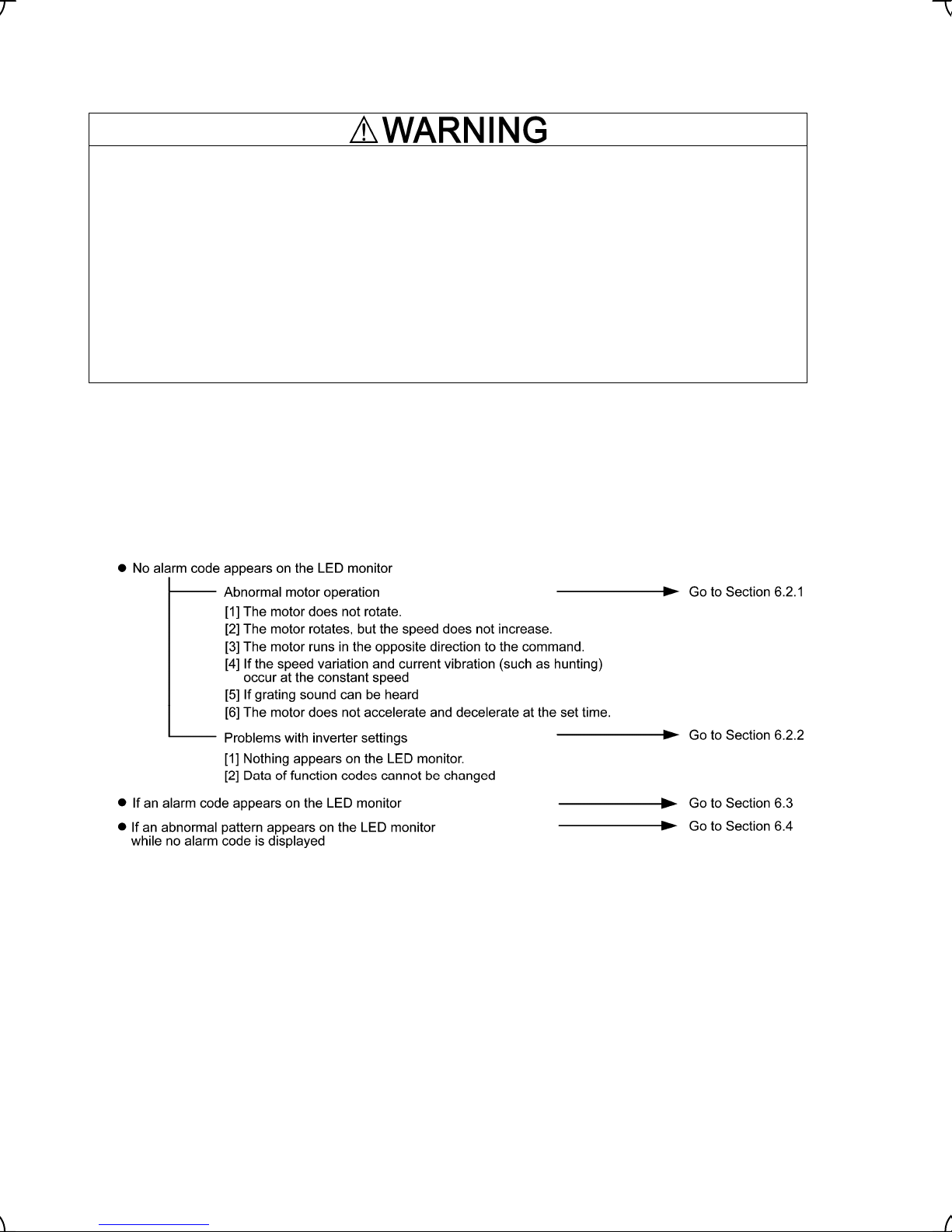
Chapter 6 TROUBLESHOOTING
6.1 Before Proceeding with Troubleshooting
If any of the protective functions have been activated, first remove the cause. Then, after checking that the all
run commands are set to off, reset the alarm. Note that if the alarm is reset while any run commands are set to
on, the inverter may supply the power to the motor which may cause the motor to rotate.
Injury may occur.
- Even though the inverter has interrupted power to the motor, if the voltage is applied to the main circuit
power input terminals L1/R, L2/S and L3/T, voltage may be output to inverter output terminals U, V, and W.
- Before setting up any internal control switches, turn the power OFF. For the inverters with a capacity of 22
kW or below, wait at least 5 minutes; for those with a capacity of 30 kW or above, wait at least 10 minutes.
Further, check that the charge lamp is unlit and make sure that the DC link bus voltage between the
terminals P (+) and N (-) has dropped below the safe voltage level (25 VDC) using a multimeter or a similar
instrument.
Electric shock may occur.
wait more than five minutes for models of 30 kW or below, or ten minutes for models of 37 kW or above.
Follow the procedure below to solve problems.
(1) First, check that the inverter is correctly wired, referring to Chapter 2, Section 2.3.6 "Wiring for main circuit
terminals and grounding terminals."
(2) Check whether an alarm code is displayed on the LED monitor.
If any problems persist after the above recovery procedure, contact your Fuji Electric representative.
6-1
Page 65

r
r
r
6.2 If No Alarm Code Appears on the LED Monitor
6.2.1 Motor is running abnormally
[ 1 ] The motor does not rotate.
Possible Causes What to Check and Suggested Measures
(1) No power supplied to the
inverter.
(2) Neither forward run
command nor reverse run
command were inputted,
or both run commands
were inputted
simultaneously (external
signal operation).
(3) A run command with
higher priority than the one
attempted was active, and
the run command was
stopped.
(4) The reference speed
(pre-ramp) was set below
the starting speed or stop
speed.
(5) A reference speed
command with higher
priority than the one
attempted was active.
(6) The enable coast-to-stop
command was effective.
(7) EN terminal circuit opens.
(8) Broken wire, incorrect
connection or poor contact
with the motor.
Check the input voltage, output voltage and interphase voltage unbalance.
Î Turn ON a molded case circuit breaker, an earth leakage circuit breake
(with overcurrent protection) or a magnetic contactor.
Î Check for voltage drop, phase loss, poor connections, or poor contacts,
and fix them if necessary.
Î If only auxiliary control power is supplied, turn ON the main power.
Check the input status of the control circuit terminals [FWD] and [REV] with
Menu 4 "I/O Checking" using the keypad.
Î Input a run command.
Î Set either FWD or REV to off if both run commands are being inputted.
Î Correct the assignment of commands FWD and REV to function codes
E98 and E99.
Î Connect the external circuit wires to control circuit terminals [FWD] and
[REV] correctly.
Î Make sure that the sink/source slide switch on the printed circuit board is
properly configured.
Check the higher priority run command with Menu 2 "Data Checking" and
Menu 4 "I/O Checking" using the keypad.
Î Correct any incorrect function code data settings in H30 or cancel the
higher priority run command.
Check that a reference speed (pre-ramp) has been entered, with Menu 4
"I/O Checking" using the keypad.
Î Set the value of the reference speed (pre-ramp) to the same or highe
than that of F23 (Starting Speed) or F25 (Stop Speed).
Î Reconsider F23 (Starting Speed) or F25 (Stop Speed), and if necessary,
change them to lower values.
Î Inspect the speed command sources, speed controller, signal converters,
switches, or relay contacts. Replace any ones that are faulty.
Î Connect the external circuit wires correctly to terminals [12], [11], [C1],
and [V2] (analog speed command operation).
Check the higher priority reference speed command setting with Menu 2
"Data Checking" and Menu 4 "I/O Checking" using the keypad, referring to
the block diagram of the reference speed command generator*.
*
Refer to the FRENIC-Lift Reference Manual (INR-SI47-1068-E), Chapter 1.
Î Correct any incorrect function code data settings (e.g. cancel the highe
priority reference speed command).
Check the data of function codes E01, E02, E03, E04, E05, E06, E07, E08,
E98 and E99 and the input signal status with Menu 4 "I/O Checking" using
the keypad.
Î Release the enable coast-to-stop command setting.
Check the EN terminal state with I/O check menu using the keypad.
Î Close the EN terminal circuit.
Check the cabling and wiring (Measure the output current).
Î Repair the wires to the motor or replace them.
6-2
Page 66

r
r
r
Possible Causes What to Check and Suggested Measures
(9) Overload Measure the output current.
Î Lighten the load or change the inverter for an upper size.
Check that a mechanical brake is in effect.
Î Release the mechanical brake.
(10) Torque generated by the
motor was insufficient.
(11) Miss-/weak-connection of
the DC reactor (DCR)
Check the data of function codes F04, F05, and P01 to P12.
Î Change the function code data to match the motor's characteristics.
Check the wiring connection.
Î Connect the DC reactor correctly. Repair or replace wires for the DC
reactor.
[ 2 ] The motor rotates, but the speed does not increase.
Possible Causes What to Check and Suggested Measures
(1) The maximum speed was
set to too low a value.
(2) The reference speed
(pre-ramp) command was
set to too low a value.
Check the data of function code F03 (Maximum Speed).
Î Readjust the data of F03 (Maximum Speed).
Check the signals for the reference speed (pre-ramp) command from the
control circuit terminals with Menu 4 "I/O Checking" using the keypad.
Î Increase the reference speed (pre-ramp).
Î If an external potentiometer for speed command source, signal converter,
switches, or relay contacts are malfunctioning, replace them.
Î Connect the external circuit wires to terminals [12], [11], [C1], and [V2]
correctly.
(3) A reference speed
command with higher
priority than the one
attempted was active and
the reference speed was
set to too low a value.
Check the settings (data) of the relevant function codes and what speed
commands are being received, through Menu 1 "Data Setting," Menu 2
"Data Checking" and Menu 4 "I/O Checking," using the keypad and referring
to the block diagram of the speed command source.
*
Refer to the FRENIC-Lift Reference Manual (INR-SI47-1068-E), Chapter 1.
Î Correct any incorrect function code data settings (e.g. cancel highe
priority speed commands, etc.).
(4) The acceleration time was
too long or too short.
Check acceleration time-related data of function codes.
Î Change the acceleration/deceleration time to match the load.
(5) Overload Measure the output current.
Î Lighten the load or change the inverter for an upper size.
Check if mechanical brake is working.
Î Release the mechanical brake.
(6) Mismatch with the
characteristics of the
motor
Check whether P01, P02, P03, P06, P07, P08, P09, P10, and P12 agree
with the parameters of the motor.
Î Set P02 and P03 properly and auto-tune the inverter for the moto
according to P04 data.
(7) The output speed did not
increase due to the current
limiting operation.
Check data of F44 (current limiter (operation level)).
Î Set data of F44 correctly, or set 999 to F44 if no current limit is needed.
Check the data of function codes F04, F05, P01, and P12 to ensure that the
V/f pattern is right.
Î Match the V/f pattern values with the motor ratings.
Î Set P02 and P03 properly and auto-tune the inverter for the moto
according to P04 data.
(8) Offset and grain data was
set incorrectly.
(9) Miss-connection of the
pulse encoder
Check the data of function codes C31, C32, C36, C37, C41, and C42.
Î Readjust the offset and gain to appropriate values.
Check the wiring.
Î Rewire to [P0], [PA], [PB], [PZ] and [CM] terminals.
6-3
Page 67

Possible Causes What to Check and Suggested Measures
(10) Miss-setting of pulse
count of the encoder
Check the magnet pole angle detection data of L02 (Pulse Encoder
(Resolution)).
Î Set up L02 for correct data.
[ 3 ] The motor runs in the opposite direction to the command.
Possible Causes What to Check and Suggested Measures
(1) Wiring has been
connected to the motor
incorrectly.
(2) Incorrect connection and
settings for run commands
and rotation direction
command FWD and REV
(3) Miss-connection of the
pulse encoder
Check the wiring to the motor.
Î Connect terminals U, V, and W of the inverter to the respective U, V, and
W terminals of the motor.
Check the data of function codes E98 and E99 and the connection to
terminals [FWD] and [REV].
Î Correct the data of the function codes and the connection.
Check the wiring.
Î Rewire to [P0], [PA], [PB], [PZ] and [CM] terminals.
Check whether the feedback signal from the pulse encoder is satisfies
following requirements.
• When the inverter runs with FWD command, a rising edge of [PA] is in
the time fame while [PB] is kept in the high level.
• When the inverter runs with REV command, a rising edge of [PA] is in
the time frame while [PB] is kept in the low level.
Î If not, interchange the signal wires between [PA] and [PB].
[ 4 ] If the speed variation and current vibration (such as hunting) occur at the constant speed
Possible Causes What to Check and Suggested Measures
(1) The reference speed
(pre-ramp) fluctuated.
Check the signals for the speed command with Menu 4 "I/O Checking" using
the keypad.
Î Increase C33, C38, and C43 (Analog Input Adjustment for Terminal [12],
[C1] and [V2] (Filter time constant)) for the speed command.
(2) The external speed
command source device
was used.
Check that there is no noise in the control signal wires from external sources.
Î Isolate the control signal wires from the main circuit wires as far as
possible.
Î Use shielded or twisted wires for the control signal.
Check whether the speed command source has not failed because of noise
from the inverter.
Î Connect a capacitor to the output terminals of the speed command source
or pass the signal wire through a ferrite core. (Refer to Chapter 2 Section
2.3.7 "Wiring for control circuit terminals.")
(3) Speed switching or
multistep speed command
was enabled.
Check whether the relay signal for switching the speed command is
chattering.
Î If any weak contact is in the relay, replace the relay.
Î Reconfigure function codes E18 (Operation Command and Multistep
Speed Agreement Timer (Mode)) and E19 (Timer).
(4) Signal cable from the
pulse encoder picks
noises up.
Check the termination of shielded sheath of the pulse encoder cable.
Î Ground the shielded sheath at the motor side.
Î Connect it to the inverter’s [CM] terminal.
Î Raise L10 (Filter Time Constant for Speed Detection).
6-4
Page 68

Possible Causes What to Check and Suggested Measures
(5) The machinery having low
stiffness in a load causes
hunting, or the output
current is oscillatory due
to irregular motor
parameters.
Check data of function codes auto speed regulator (ASR).
Î Decrease L36 (ASR (P constant at high speed)) and L38 (ASR (P
constant at low speed)).
Î Increase L37 (ASR (I constant at high speed)) and L39 ASR ((I constant at
low speed)).
Check that the motor vibration is suppressed if you decrease level of F26
(Motor Sound (Carrier frequency)).
Î Decrease level of F26 (Motor Sound (Carrier frequency)).
[ 5 ] If grating sound can be heard from the motor
Possible Causes What to Check and Suggested Measures
(1) The carrier frequency was
set too low.
(2) The ambient temperature
of the inverter was too
high (when automatic
lowering of the carrier
frequency was enabled by
Check the data of function codes F26 (Motor Sound (Carrier frequency)).
Î Increase F26 (Motor Sound (Carrier frequency)).
Measure the temperature inside the enclosure of the inverter.
Î If it is over 40℃, lower it by improving the ventilation.
Î Lower the temperature of the inverter by reducing the load.
Note) If you set H98 (bit 0 = 0), an
0h1, 0h3,
or
0lu
alarm may occur.
H98).
(3) Resonance with the load Check the precision of the mounting of the load or check whether there is
resonance with the enclosure or likes.
Î Disconnect the motor and run it without the inverter, and determine where
the resonance comes from. Upon locating the cause, improve the
characteristics of the source of the resonance.
[ 6 ] The motor does not accelerate and decelerate at the set time.
Possible Causes What to Check and Suggested Measures
(1) Selected S-curve
accel./decel. pattern
miss-matches with the
mutistep speed command.
Check the related function code data and the issuing timing of the multistep
speed command.
Î Check and correct F07, F08, and E10 to E17 (Acceleration/Deceleration
Time), L11 to L18 (Multistep Speed Command Combination), and L19 to
L28 (S-curve Setting).
(2) The speed was controlled,
because the current limit
operated.
Check that the setting of F44 (Current limiter (Level)) is reasonable.
Î Readjust the setting of F44 to appropriate value.
Î Increase the acceleration/deceleration time.
Î Correct P12 (Motor (Rated slip)).
(3) Overload Measure the output current.
Î Lighten the load or change the inverter for an upper size.
(4) Torque generated by the
motor was insufficient.
Check the data of motor parameters.
Î Match data of F04, F05, and P01 to P12 with data on the motor rating
plate.
(5) An external speed
command source is being
used.
Check that there is no noise superimposed on the external signal wires.
Î Isolate the control signal wires from the main circuit wires as far as
possible.
Î Use shielded wire or twisted wire for the control signal wires.
Î Connect a capacitor to the output terminals of the speed command source
or pass the signal wire through a ferrite core. (Refer to Chapter 2 Section
2.3.7 "Wiring for control circuit terminals.")
Î Check and correct the filter time constant.
Î Check and correct F07 and F08 (Acceleration/Deceleration Time).
6-5
Page 69

r
r
Possible Causes What to Check and Suggested Measures
(6) The V2/PTC switch was
turned to PTC (when [V2]
was being used).
Check whether control terminal [V2] is not set to the PTC thermistor input
mode. Confirm SW4. (Refer to Chapter 2 Section 2.3.8 "Setting up slide
switches.")
Î Turn the V2/PTC switch on the printed circuit board to V2.
6.2.2 Problems with inverter settings
[ 1 ] Nothing appears on the multi-function keypad.
Possible Causes What to Check and Suggested Measures
(1) No power supplied to the
inverter (main circuit
power, auxiliary power for
control circuit).
Check the power supply and measure the input voltage.
Î Turn on the molded case circuit breaker, earth leakage circuit breake
(with overcurrent protection) or magnetic contactor on the primary circuit.
Î Check for voltage drop, phase loss, weak connections, or weak contacts,
and fix them if necessary.
(2) The power for the control
circuit did not reach a high
enough level.
Check if the short bar has been removed between terminals [P1] and [P (+)]
or if there is poor contact between the short bar and the terminals.
Î Connect the short bar or DC reactor between terminals [P1] and [P (+)] o
retighten the screws.
(3) The keypad was not
properly connected to the
inverter.
Check whether the keypad is properly connected to the inverter.
Î Remove the keypad, put it back, and see whether the problem persists.
Î Replace the keypad with another one and check whether the problem
persists.
When running the inverter at a remote site, ensure that the extension cable
is securely connected both to the keypad and to the inverter.
Î Disconnect the cable, reconnect it, and see whether the problem persists.
Î Replace the keypad with another one and check whether the problem
persists.
[ 2 ] Data of function codes cannot be changed
Possible Causes What to Check and Suggested Measures
(1) An attempt was made to
change function code data
that cannot be changed
when the inverter is
running.
(2) The data of the function
codes is protected or in
the password-protected
state.
(3) The key was not
pressed.
Check if the inverter is running with Menu 3 "Drive Monitoring" using the
keypad and then confirm whether the data of the function codes can be
changed when the motor is running by referring to the function code tables.
Î Stop the motor then change the data of the function codes.
Check the data of function code F00 (Data Protection).
Î Change the data of F00 from "1" to "0."
Î If the inverter is in password-protected state, set the password up into
F00.
Check whether you have pressed the key after changing the function
code data.
Î Press the
key after changing the function code data.
6-6
Page 70
6.3 If an Alarm Code Appears on the LED Monitor
Quick reference table of alarm codes
Alarm
code
0c1
0c2
0c3
0u1
0u2
0u3
lu
lin
0h1
0h2
0h3
0h4
0l1
0lu
Name Refer to
Overcurrent
Overvoltage
Undervoltage
Input phase loss
Heat sink overheat
External alarm
Internal air overheat
Motor protection (PTC thermistor)
Motor overload
Inverter overload
6-7
6-8
6-8
6-9
6-9
6-10
6-10
6-10
6-11
6-11
Alarm
code
er1
er2
er3
er4
er5
er6
er7
er8
erh
ecf
pg
ert
0s
ere
Name Refer to
Memory error
Keypad communications error
CPU error
Option communications error
Option error
Operation error
Tuning error
RS485 communications error
Hardware error (option detection)
EN circuit fault
Broken wiring in the PG
CAN bus communications error
Over speed error
Speed mismatching
(Out of speed control)
6-12
6-12
6-12
6-13
6-13
6-13
6-13
6-14
6-15
6-15
6-16
6-16
6-16
6-17
pbf
Charger circuit fault
6-18
0t
Over torque current
6-18
0c
[ 1 ]
n Overcurrent
Problem The inverter momentary output current exceeded the overcorrect level.
OC1
Overcurrent occurred during acceleration.
OC2 Overcurrent occurred during deceleration.
OC3 Overcorrect occurred when running at a constant speed.
Possible Causes What to Check and Suggested Measures
(1) The inverter output
terminals were
short-circuited.
Remove the wires connected to the inverter output terminals (U, V, and W)
and measure the interphase resistance of the wires. Check if the resistance
is too low.
Î Remove the part that short-circuited (including replacement of the wires,
relay terminals and motor).
(2) Ground faults occurred at
the inverter output
terminals.
Remove the wires connected to the inverter output terminals (U, V, and W)
and perform a Megger test.
Î Remove the part that short-circuited (including replacement of the wires,
relay terminals and motor).
(3) Loads were too heavy. Measure the motor current with a measuring device, and to trace the current
trend. Therefore, use this information to judge if the trend is over the
calculated load value for your system design.
ÎIf the load is too heavy, change the inverter for an upper size.
Trace the current trend and check if there are any sudden changes in the
current.
Î Change the inverter for an upper size.
6-7
Page 71

f
f
r
f
Possible Causes What to Check and Suggested Measures
(4) The acceleration/
deceleration time was too
short.
Check that the motor generates enough torque required during
acceleration/deceleration. That torque is calculated from the moment o
inertia for the load and the acceleration/deceleration time.
Î Increase F07, F08, and E10 to E17 (Acceleration/Deceleration Time).
Î Change the inverter for an upper size.
(5) A high intensity noise was
given to the inverter.
Check if noise control measures are appropriate (e.g., correct grounding and
routing of control and main circuit wires).
Î Take the countermeasure to noises.
Î Insert a surge absorber into a noise source such as an activation coil o
MC or electro-magnetic solenoids.
(6) Invalid motor parameters
set.
Check the motor parameters (P codes).
Î Correct the motor parameters by replacing with printed ones on the moto
nameplate
[ 2 ]
0u
n Overvoltage
Problem The DC link bus voltage was over the detection level of overvoltage.
OU1
Overvoltage occurs during the acceleration.
OU2 Overvoltage occurs during the deceleration.
OU3 Overvoltage occurs during running at constant speed.
Possible Causes What to Check and Suggested Measures
(1) The power supply voltage
was over the range of the
inverter’s specifications.
(2) A surge current entered
the input power source.
Measure the input voltage.
Î Decrease the voltage to within that of the specifications.
If within the same power source a phase-advancing capacitor is turned ON
or OFF or a thyristor converter is activated, a surge (temporary precipitous
rise in voltage or current) may be caused in the input power.
Î Install a DC reactor.
(3) The deceleration time was
too short compared with
the inertia of the load.
(4) Braking load was too
heavy.
Calculate the deceleration time from the inertia of the load and the braking
torque again.
Î Increase the deceleration time.
Compare the braking torque of the load with that of the inverter.
Î Select a minimum resistance braking resistor connectable to the inverter.
Î Change the inverter for an upper size.
(5) A high intensity noise was
given to the inverter.
Check if noise control measures are appropriate (e.g., correct grounding and
routing of control and main circuit wires).
Î Take the countermeasure to noises.
Î Insert a surge absorber into a noise source such as an activation coil o
MC or electro-magnetic solenoids.
(6) No connected braking
resistor
Check whether the braking resistor is connected to the inverter correctly.
Î Check the braking resistor is connected to terminals P (+) and DB
correctly. Or, retighten screws/nuts.
Î Check whether any terminal bites the wire sheath. If so correct it.
[ 3 ]
lu
Undervoltage
Problem DC link bus voltage was below the undervoltage detection level.
Possible Causes What to Check and Suggested Measures
(1) A momentary power failure
occurred.
Î Reset the alarm.
6-8
Page 72

Possible Causes What to Check and Suggested Measures
(2) The power supply voltage
did not reach the range of
the inverter’s
Measure the input voltage.
Î Increase the voltage to within that of the specifications.
specifications.
(3) Peripheral equipment for
the power circuit
malfunctioned, or the
connection was incorrect.
(4) Other loads were
connected to the same
power source and required
To locate the peripheral equipment malfunctioned or incorrect connection,
measure the input voltage.
Î Replace any faulty peripheral equipment or correct any incorrect
connections.
Measure the input voltage and check the voltage variation.
Î Reconsider the power system configuration.
a large current to start
running to the extent that it
caused a temporary
voltage drop on the supply
side.
(5) Inverter’s inrush current
caused the power voltage
drop because power
transformer capacity was
insufficient.
Check if the alarm occurs when you switch on a molded case circuit breaker,
an earth leakage circuit breaker (with overcurrent protection) or a magnetic
contactor.
ÎReconsider the capacity of the power source transformer.
lin
[ 4 ]
Input phase loss
Problem Input phase loss occurred, or interphase voltage unbalance rate was large.
Possible Causes What to Check and Suggested Measures
(1) Main circuit power input
wires broken.
(2) The terminal screws for
the main circuit power
input of the inverter were
Measure the input voltage.
Î Repair or replace the wires.
Check if the screws on the inverter input terminals have become loose.
Î Tighten the terminal screws to the recommended torque.
not tight enough.
(3) Interphase unbalance rate
of three-phase voltage
was too large.
(4) Overload cyclically
occurred.
Measure the input voltage.
Î Change the inverter for an upper size.
Measure ripple wave of DC link circuit voltage.
Î If the ripple is large, raise the inverter capacity.
You can disable input phase loss protection using the function code H98.
[ 5 ]
0h1
Cooling fin overheat
Problem Temperature around heat sink rose.
Possible Causes What to Check and Suggested Measures
(1) Temperature around the
inverter exceeded that of
inverter specifications.
Measure the temperature around the inverter.
Î Lower the temperature around the inverter (e.g., ventilate the enclosure
well).
(2) Air vent is blocked. Check if there is sufficient clearance around the inverter.
Î Increase the clearance.
Check if the heat sink is not clogged.
Î Clean the heat sink.
6-9
Page 73

Possible Causes What to Check and Suggested Measures
(3) Cumulative running time
of the cooling fan
exceeded the standard
period for replacement, or
the cooling fan
malfunctioned.
Check the cumulative running time of the cooling fan.
Î Replace the cooling fan.
Visually check whether the cooling fan rotates abnormally.
Î Replace the cooling fan.
(4) Load was too heavy. Measure the output current.
Î Decease F26 (Motor Sound (Carrier frequency)).
[ 6 ]
0h2
External alarm
Problem External alarm was inputted THR.
(in case external alarm THR is assigned to one of digital input terminals [X1] through [X8], [FWD],
or [REV])
Possible Causes What to Check and Suggested Measures
(1) An alarm function of the
external equipment was
activated.
Inspect external equipment operation.
Î Remove the cause of the alarm that occurred.
(2) Incorrect connection. Check if the wire for the external alarm signal is correctly connected to the
terminal to which the "Trip command (External failure)" has been assigned
(Any of E01, E02, E03, E04, E05, E06, E07, E08, E98, and E99 is set to
"9.").
Î Connect the wire for the alarm signal correctly.
(3) Incorrect settings. Check whether the " Trip command (External failure)" has not been
connected to an unassigned terminal (None of E01, E02, E03, E04, E05,
E06, E07, E08, E98, and E99).
Î Correct the assignment.
Check whether the logic assignment (normal/negative) of the external signal
agrees with that of thermal command THR assigned by any of E01, E02,
E03, E04, E05, E06, E07, E08, E98, and E99.
Î Ensure that logic agrees each other.
[ 7 ]
0h3
Inverter inside overheat
Problem The temperature inside the inverter exceeded the allowable limit.
Possible Causes What to Check and Suggested Measures
(1) The ambient temperature
exceeded the allowable
limit specified for the
inverter.
[ 8 ]
0h4
Motor protection (PTC thermistor)
Problem Temperature of the motor rose abnormally.
Possible Causes What to Check and Suggested Measures
(1) Temperature around the
motor exceeded that of
motor specifications.
(2) Cooling system for the
motor malfunctioned.
Measure the ambient temperature.
Î Lower the ambient temperature by improving the ventilation of the system
enclosure or the like.
Measure the temperature around the motor.
Î Lower the temperature.
Check if the cooling system of the motor is operating normally.
Î Repair or replace the cooling system of the motor.
6-10
Page 74

y
Possible Causes What to Check and Suggested Measures
(3) Load was too heavy. Measure the output current.
Î Lower the temperature around the motor.
Î Increase F26 (Motor Sound (Carrier frequency)).
(4) The set operation level
(H27) of the PTC
thermistor for overheat
Check the thermistor specifications and recalculate the detection voltage.
Î Reconsider the data of function code H27 (PTC Thermistor Input (Level)).
protection was
inadequate.
(5) A PTC thermistor and
pull-up resistor were
connected incorrectly or
the resistance was
Check the connection and the resistance of the pull-up resistor.
Î Correct the connections and replace the resistor with one with an
appropriate resistance.
inadequate.
(6) The V/f pattern did not
match the motor.
Check whether data of function codes F04, F05, and P01 to P12 match the
values on the nameplate on the motor.
Î Match the function code data to the values on the nameplate of the motor.
Î After the setup of P02 and P03 auto-tune the inverter for the motor b
P04.
(7) Wrong settings Although no PTC thermistor is used, the V2/PTC switch is turned to PTC,
which means that the thermistor input is active on the PTC (H26).
Î Set H26 (PTC Thermistor Input (Mode)) to "0" (Disable).
0l1
[ 9 ]
Motor overload
Problem Electronic thermal function for motor overload detection was activated.
Possible Causes What to Check and Suggested Measures
(1) The characteristics of
electronic thermal motor
protection did not match
those of the motor
Check the motor characteristics.
Î Reconsider the data of function codes F10 and F12.
Î Use an external thermal relay.
overload.
(2) Activation level for the
electronic thermal motor
protection was
Check the continuous allowable current of the motor.
Î Reconsider and change the data of function code F11.
inadequate.
(3) Load was too heavy. Measure the output current.
Î Review characteristics or properties of the machinery.
0lu
[ 10 ]
Inverter overload
Problem Temperature inside inverter rose abnormally.
Possible Causes What to Check and Suggested Measures
(1) Temperature around the
inverter exceeded that of
inverter specifications.
Measure the temperature around the inverter.
Î Lower the temperature (e.g., ventilate the enclosure well).
(2) Load was too heavy. Measure the output current.
Î Decrease F26 (Motor Sound (Carrier frequency)).
(3) Air vent is blocked. Check if there is sufficient clearance around the inverter.
Î Increase the clearance.
Check if the heat sink is not clogged.
Î Clean the heat sink.
6-11
Page 75

Possible Causes What to Check and Suggested Measures
(4) The service life of the
cooling fan has expired or
the cooling fan
malfunctioned.
Check the cumulative running time of cooling fan.
Î Replace the cooling fan.
Visually check that the cooling fan rotates normally.
Î Replace the cooling fan.
[ 11 ]
er1
Memory error
Problem Error occurred in writing the data to the memory in the inverter.
Possible Causes What to Check and Suggested Measures
(1) While the inverter was
writing data (especially
initializing data or copying
data), power supply was
turned OFF and the
Check whether pressing the
code data are initialized by setting the data of H03 to 1.
Î Return the initialized function code data to their previous settings, and
restart the operation.
key can reset the alarm after the function
voltage for the control
circuit dropped.
(2) A high intensity noise was
given to the inverter while
data (especially initializing
data) was being written.
Check if appropriate noise control measures have been implemented (e.g.,
correct grounding and routing of control and main circuit wires). Also,
perform the same check as described in (1) above.
Î Improve the countermeasure to noises. Alternatively, return the initialized
function code data to their previous settings, and restart the operation.
(3) The control circuit failed.
Initialize the function code data by setting H03 to 1, and reset the alarm by
pressing the
key and check that the alarm goes on.
Î This problem was caused by a failure of the printed circuit board (PCB)
(on which the CPU is mounted). Contact your Fuji Electric representative.
[ 12 ]
er2
Keypad communications error
Problem A communications error occurred between the keypad and the inverter.
(When the inverter is running in the local mode.)
Possible Causes What to Check and Suggested Measures
(1) Break in the
communications cable or
poor contact.
(2) A high intensity noise was
given to the inverter.
Check continuity of the cable, contacts and connections.
Î Re-insert the connector firmly.
Î Replace the cable.
Check if appropriate noise control measures have been implemented (e.g.,
correct grounding and routing of control and main circuit wires).
Î Improve the countermeasure to noises.
(3) The keypad
malfunctioned.
Check that alarm
inverter.
er2
does not occur if you connect another keypad to the
Î Replace the keypad.
6-12
Page 76

r
r
[ 13 ]
er3
CPU error
Problem A CPU error (e.g. erratic CPU operation) occurred.
Possible Causes What to Check and Suggested Measures
(1) A high intensity noise was
given to the inverter.
Check if appropriate noise control measures have been implemented (e.g.,
correct grounding and routing of control and main circuit wires).
Î Improve the countermeasure to noises.
[ 14 ]
er4
Option communications error
Problem A communications error occurred between the option card and the inverter.
Possible Causes What to Check and Suggested Measures
(1) There was a problem with
the connection between
the bus option card and
the inverter.
Check whether the connector on the bus option card is properly mating with
the connector of the inverter.
Î Reload the bus option card into the inverter.
(2) There was a high intensity
noise from outside.
Check whether appropriate noise control measures have been implemented
(e.g. correct grounding and routing of control and main circuit wires and
communications cable).
Î Improve the countermeasure to noises.
(3) Any faults is in the wiring
connection between the
pulse encoder and the
option card.
Check whether the pulse encoder and the option card are wired each othe
correctly.
Î Wire them correctly.
er5
[ 15 ]
Option error
Problem Option card-related error occurs.
Possible Causes What to Check and Suggested Measures
(1) The pulse encoder is
broken.
(2) Wrong pulse encoder is
connected.
Î Replace the pulse encoder for new one.
Check whether the pulse encoding is specified within encoder specifications
described in the option card instruction manual.
Î Replace the pulse encoder for a correct one.
(3) Any faults is in the wiring
connection between the
pulse encoder and the
option card.
Check whether the pulse encoder and the option card are wired each othe
correctly.
Î Wire them correctly.
6-13
Page 77

[ 16 ]
er6
Run operation error
Problem You incorrectly operated the inverter.
Possible Causes What to Check and Suggested Measures
(1) Wrong setup of multistep
speed commands
(2) The brake does not follow
the brake command.
[ 17 ]
er7
Tuning error
Problem Auto-tuning failed.
Possible Causes What to Check and Suggested Measures
(1) A phase was missing
(There was a phase loss)
in the connection between
the inverter and the motor.
(2) V/f or the rated current of
the motor was not properly
set.
(3) The rated capacity of the
motor was significantly
different from that of the
inverter.
(4) The motor was a special
type.
Check whether all function codes of L11 to L18 (Multistep Speed Command
Combination) are configured with different data each other.
Î Reconfigure the commands.
Check whether the brake status signal BRKE input agrees with the brake
command BRKS.
Î Reconfigure L84 (Brake Control (Brake check time)).
Î Properly connect the motor to the inverter.
Î If any contactor is inserted between the inverter and motor, turn the
contactor on anytime while tuning.
Check whether the data of function codes F04, F05, P02, and P03 agrees
with the specifications of the motor.
Check whether the rated capacity of the motor is smaller than that of the
inverter by three or more orders of class or larger by two or more sizes in
capacity.
Î Review the inverter capacity.
Î Set motor parameters (P06, P07, P08, and P12) up manually.
Î Set motor parameters (P06, P07, P08, and P12) up manually.
(5) Wrong sequence
operation.
(6) Excessive overcurrent is
flown.
Î Do not turn the [EN] terminal OFF while tuning.
Î Do not turn the run command OFF while tuning.
Î Do not press the
Î Do not turn the enable coast-to-stop command BX ON while tuning.
Î Do not turn the force to decelerate command DRS OFF while tuning.
Check whether any wires between the inverter and the motor is
short-circuited or ground-faulted.
Î Remove the fault factor/s.
Check whether data of function codes (F04, F05, P02, and P03) agrees with
motor specifications.
Î Correct the mismatch data.
key ON the keypad while tuning.
For details of tuning errors, refer to “Errors during Tuning” in Chapter 4, Section 4.1.3 “Preparation before
running the motor for a test – Setting function code data.”
6-14
Page 78

r
[ 18 ]
er8
RS485 communications error
Problem A communications error occurred during RS485 communications.
Possible Causes What to Check and Suggested Measures
(1) Conditions for
communications differ
between the inverter and
host equipment.
(2) Even though y08 (no
response error detection
time) has been set,
communications is not
Compare the settings of the y codes (y01 to y10) with those of the host
equipment.
Î Correct any settings that differ.
Check the host equipment.
Î Change the settings of the host equipment software, or make the no
response error detection time be ignored (y08=0).
performed within the
specified cycle.
(3) Host equipment (e.g.,
PLCs and personal
computers) did not
Check the host equipment.
Î Remove the cause of the equipment error.
operate due to incorrect
settings and/or defective
software/hardware.
(4) Converters (e.g., RS485
converter) did not operate
due to incorrect
connections and settings,
Check the RS485 converter (e.g., check for poor contact).
Î Change the various RS485 converter settings, reconnect the wires, o
replace hardware (such as recommended devices) as appropriate.
or defective hardware.
(5) Broken communications
cable or poor contact.
Check continuity of the cable, contacts and connections.
Î Replace the cable.
(6) A high intensity noise was
given to the inverter.
Check if appropriate noise control measures have been implemented (e.g.,
correct grounding and routing of control and main circuit wires).
Î Improve the countermeasure to noises.
Î Improve the countermeasure to noises on the host side.
Î Replace the RS485 level converter with a recommended insulated
converter.
6-15
Page 79

[ 19 ]
erh
Hardware error (option detection)
Problem The inverter does not detect an option card.
Possible Causes What to Check and Suggested Measures
(1) The option card is broken. You need to replace the option card.
Î Consult your Fuji Electric representative.
[ 20 ]
ecf
EN terminal circuit failure
Problem The detection circuit for EN terminal signal is broken.
Possible Causes What to Check and Suggested Measures
(1) The circuit is broken. You need to replace the control printed circuit board (CPCB.)
Î Consult your Fuji Electric representative.
[ 21 ]
pg
PG disconnection error
Problem Any pulse encoder signal wires is broken.
Possible Causes What to Check and Suggested Measures
(1) Any wire between the
pulse encoder and the
option card is broken.
Check whether the pulse coder is correctly connected to the option card.
Î Check that the pulse encoder signals are wired to the option card’s
terminals specified by the instruction manual. If so, retighten the fixing
screws.
Î Check that any terminal bites the wire sheath. If so correct it.
(2) A high intensity noise was
given to the inverter.
Check if appropriate noise control measures have been implemented (e.g.,
correct grounding and routing of control and main circuit wires).
Î Improve the countermeasure to noises.
Î Separate the control wires as far from the main power wires as possible.
ert
[ 22 ]
CAN bus communications error
Problem A communications error occurred during CAN bus communication.
Possible Causes What to Check and Suggested Measures
(1) Wrong transmission speed Check the transmission speed consistency between the inverter (y24) and
host equipment.
Î Correct the mismatch if any.
(2) Host equipment
malfunction in hardware,
operating system, or their
Review the host equipment.
Î Remove or repair the error factor/s in the host equipment.
configuration
(3) Disconnection or weak
connection of the
communications cable
(4) A high intensity noise was
given to the inverter.
Check that cable conductivity and contact state at the connector in each
counterpart.
Î Replace the communications cable.
Check if appropriate noise control measures have been implemented (e.g.,
correct grounding and routing of control and main circuit wires).
Î Improve the countermeasure to noises.
Î Improve the countermeasure to noises on the host side..
6-16
Page 80

[ 23 ] 0s Over speed error
Problem The motor runs in excess-speed (where Motor speed ≥ (F03 × 1.2))
Possible Causes What to Check and Suggested Measures
(1) Wrong configuration Check relationship between set data for P01 (Motor (number of poles)) and
L02 (Pulse Encoder (Resolution)).
Î Set data of P01 up so as to agree with the motor parameter.
Î Set data of L02 up so as to agree with the encoder resolution.
Check data of F03 (Maximum Speed).
Î Set data of F03 so as to agree with the motor running speed.
(2) A high intensity noise was
given to the inverter.
Check if appropriate noise control measures have been implemented (e.g.,
correct grounding and routing of control and main circuit wires).
Î Improve the countermeasure to noises.
(3) An external speed
controller is used.
Check whether signal cable from the external controller picks noises up.
Î Separate the control wires as far from the main power wires as possible.
Î Use a shielded or twisted-pair wire for the control signal wiring
connection.
Check whether noises from the inverter affect the speed controller to
malfunction.
Î Connect a noise suppressor capacitor between the controller output
terminals or pass the signal wire through a ferrite core.
6-17
Page 81

r
[ 24 ]
ere
Out of control speed
Problem An out of control error (PG failure) occurs between the speed command and the speed feedback.
Possible Causes What to Check and Suggested Measures
(1) Wrong configuration Check data of function code L90, L91, and L92.
Î If the speed fluctuation is within the allowable range, then set data of L90
(PG Error Detection (Mode)) up to 0.
Î Widen L91 (PG Error Detection (Detection level)).
Î Lengthen L92 (PG Error Detection (Detection time)).
Check relationship between set data for P01 (Motor (number of poles)) and
L02 (Pulse Encoder (Resolution)).
Î Set data of P01 up so as to agree with the motor parameter.
Î Set data of L02 up so as to agree with the encoder resolution.
(2) Overload Measure the output current.
Î Lower the load.
Check whether the mechanical brake is activated.
Î Release it.
(3) Output speed cannot
increase by a reaction of
the current limiter.
Check data of F44 (Current Limiter (Level)).
Î Change data of F44 so as to agree with desired operations, or set it up to
999 if no speed limiting is needed.
Check whether the V/f pattern is correctly profiled in function codes, F04,
F05, and P01 to P12.
Î Make the V/f pattern match the motor rating.
Î Change the V/f pattern so as to agree with the motor used.
(4) Wrong motor parameters Check data of function codes, P01, P02, P03, P06, P07, P09, P10, and P12
agrees with parameters of the motor.
Î Set P02 and P03 properly and auto-tune the inverter for the moto
according to P04 data.
(5) Miss-connection of the
pulse encoder
Check the wiring.
Î Rewire to [P0], [PA], [PB], [PZ] and [CM] terminals.
Check whether the feedback signal from the pulse encoder is satisfies
following requirements.
• When the inverter runs with FWD command, a rising edge of [PA] is in
the time fame while [PB] is kept in the high level.
• When the inverter runs with REV command, a rising edge of [PA] is in
the time frame while [PB] is kept in the low level.
Î If not, interchange the signal wires between [PA] and [PB].
(6) Wiring has been
connected to the motor
incorrectly.
(6) Gain of auto speed
Check the wiring to the motor.
Î Connect terminals U, V, and W of the inverter to the respective U, V, and
W terminals of the motor.
Î Reconfigure L36 to L39 (ASR).
regulator (ASR) was too
big or small.
6-18
Page 82

r
r
[ 25 ]
0t
Over torque current
Problem Reference torque current became excessive.
Possible Causes What to Check and Suggested Measures
(1) The inverter output wiring
has been disconnected.
Wiring from the inverter output terminal (U, V, and W) to the motor is
confirmed with the tester.
Î The disconnection part is removed.
Î Check that any terminal bites the wire sheath. If so correct it.
The magnetic contactor is set up on the output side of the inverter (the
second side). Whether the magnetic contactor is driven while opened is
checked.
Î After the magnetic contactor is short-circuited, the inverter is operated.
(2) Any wire between the pulse
encoder and the option card is
broken.
Check whether the pulse coder is correctly connected to the option card.
Î Check that the pulse encoder signals are wired to the option card’s
terminals specified by the instruction manual. If so, retighten the fixing
screws.
Î Check that any terminal bites the wire sheath. If so correct it.
(3) Loads were too heavy.
Measure the motor current with a measuring device, and to trace the current
trend. Therefore, use this information to judge if the trend is over the
calculated load value for your system design.
ÎIf the load is too heavy, change the inverter for an upper size.
Trace the current trend and check if there are any sudden changes in the
current.
Î Change the inverter for an upper size.
(4) The acceleration/deceleration
time was too short.
Check that the motor generates enough torque required during
acceleration/deceleration. That torque is calculated from the moment of
inertia for the load and the acceleration/deceleration time.
Î The setting of acceleration/deceleration time is changed long.
Î Change the inverter for an upper size.
(5) Invalid motor parameters set.
Check the motor parameters (P codes).
Î Correct the motor parameters by replacing with printed ones on the moto
nameplate
(6) The magnetic pole position
Î Tuning the magnetic pole position.(L03)
is wrong.
For the magnetic pole position tuning refer to the instruction manual of the option.
pbf
[ 26 ]
Charger circuit fault (37 kW or above (400 V Series))
Problem The magnetic contactor for short-circuiting the resistor for charging failed to work.
Possible Causes What to Check and Suggested Measures
(1) Control power was not
supplied to the magnetic
contactor intended for
short-circuiting the charging
resistor.
Whether the power supply is connected with auxiliary power input terminals
(R0, T0) is confirmed.
Î It wires correctly. (Refer to Chapter 2)
Î Check that any terminal bites the wire sheath. If so correct it.
The voltage of the auxiliary power input terminals is measured, and whethe
power switching connectors [CN UX] is correctly connected is confirmed. (37
kW or above (400V series))
Î Power switching connectors [CN UX] is correctly connect.
(Refer to Chapter 2)
6-19
Page 83

6.4 If an Abnormal Pattern Appears on the LED Monitor while No Alarm Code is Displayed
[ 1 ] – – – – (center bar) appears
Problem A center bar (– – – –) has appeared on the LCD monitor.
Possible Causes What to Check and Suggested Measures
(1) Connection to the keypad
was in weak connection.
[ 2 ] _ _ _ _ (under bar) appears
Prior to proceed, check that pressing the
LED display.
Check connectivity of the extension cable for the keypad used in remote
operation.
Î Replace the cable.
key does not take effect for the
Problem An under bar ( _ _ _ _ ) appeared on the LED monitor when you pressed the
key or entered a run forward command FWD or a run reverse command REV. The motor did not
start.
Possible Causes What to Check and Suggested Measures
(1) The voltage of the DC link
bus was low.
Select Menu 5 "Maintenance Information" in Programming mode on the
keypad, and check the voltage of the DC link bus, which should be: 400 VDC
or below for 3-phase 400V.
Î Connect the inverter to a power supply that meets its input specifications.
(2) The main power is not ON,
while the auxiliary input
power to the control circuit
Check that the main power is turned ON.
Î If it is not ON, turn it ON.
is supplied.
key or the
6-20
Page 84

Chapter 7 MAINTENANCE AND INSPECTION
Perform daily and periodic inspection to avoid trouble and keep reliable operation for a long time. Take care of the
following items during work.
• Before starting inspection, turn the power OFF. For the inverters with a capacity of 22 kW or below, wait at
least 5 minutes; for those with a capacity of 30 kW or above, wait at least 10 minutes. Further, check that the
charge lamp is unlit and make sure that the DC link bus voltage between the terminals P (+) and N (-) has
dropped below the safe voltage level (25 VDC) using a multimeter or a similar instrument.
Electric shock may occur.
• Maintenance, inspection, and parts-replacement should be made only by authorized persons.
• Take off the wristwatch, rings and other metallic matter before starting work.
• Use insulated tools.
• Never modify the inverter.
Electric shock or injuries could occur.
7.1 Daily Inspection
Visually inspect errors in the state of operation from the outside without removing the covers while the inverter
operates or while it is turned ON.
- Check if the expected performance (satisfying the standard specification) is obtained.
- Check if the surrounding environment satisfies Chapter 2, Section 2.1 "Operating Environment."
- Check for abnormal noise, odor, or excessive vibration.
- Check for traces of overheating, discoloration and other defects.
7.2 Periodic Inspection
Perform periodic inspection by following the items of the list of periodic inspection in Table 7.1. Before performing
periodic inspection, be sure to stop the motor, turn OFF the inverter, and shut down power supply. Then remove
the covers of the control and main circuit terminal blocks.
Table 7.1 List of Periodic Inspections
Check part Check item How to inspect Evaluation criteria
Environment
Voltage
1) Check the ambient temperature,
humidity, vibration and atmosphere
(dust, gas, oil mist, or water drops).
2) Check if tools or other foreign matter
or dangerous objects are left around
the equipment.
Check if the voltages of the main and
control circuit are correct.
1) Check visually or
measure using
apparatus.
2) Visual inspection
Measure the voltages
using a multimeter or
the like.
1) The standard
specification must be
satisfied.
2) No foreign or
dangerous objects
are left.
The standard
specification must be
satisfied.
7-1
Page 85

Table 7.1 Continued
Check part Check item How to inspect Evaluation criteria
Structure such
as frame and
cover
Common
Conductor
and wire
Terminal
block
Filtering
capacitor
Main circuit
1) Abnormal noise and excessive
vibration
2) Loose screws (tightened parts)
3) Deformation and breakage
4) Discoloration and deformation
caused by overheat
5) Check for foulness and dust.
1) Check if bolts and screws are tight
and not missing.
2) Check the devices and insulators for
deformation, cracks, breakage and
discoloration caused by overheat and
deterioration.
3) Check for foulness and dust.
1) Check the conductor for discoloration
and distortion caused by overheat.
2) Check the sheath of the cable for
cracks and discoloration.
Check that the terminals are not
damaged.
1) Check for electrolyte leakage,
discoloration, cracks and swelling of
the case.
2) Check if the safety valve does not
protrude remarkably.
3) Measure the capacitance if
necessary.
1) Visual or hearing
inspection
2) Retighten.
3), 4), 5)
Visual inspection
1) Retighten.
2), 3)
Visual inspection
1), 2)
Visual inspection
Visual inspection No abnormalities
1),2)
Visual inspection
3) Measure discharge
time with
capacitance probe.
1), 2), 3), 4), 5)
No abnormalities
1), 2), 3)
No abnormalities
1), 2)
No abnormalities
1),2)
No abnormalities
3) The discharge time is
not shorter than time
specified by the
replacement manual.
Magnetic
contactor
and relay
Printed
circuit board
Control circuit
Cooling fan
Cooling system
Ventilation
path
1) Check for chatters during operation.
2) Check for rough contacts.
1) Check for loose screws and
connectors.
2) Check for odor and discoloration.
3) Check for cracks, breakage,
deformation and remarkable rust.
4) Check the capacitors for electrolyte
leaks and deformation.
1) Check for abnormal noise and
excessive vibration.
2) Check for loose bolts.
3) Check for discoloration caused by
overheat.
Check the heat sink, intake and exhaust
ports for clogging and foreign matter.
1) Hearing inspection
2) Visual inspection
1) Retighten.
2) Smelling and visual
inspection
3), 4)
Visual inspection
1) Hearing and visual
inspection, or turn
manually (be sure to
turn the power OFF).
2) Retighten.
3) Visual inspection
Visual inspection No abnormalities
1), 2)
No abnormalities
1), 2), 3), 4)
No abnormalities
1) Smooth rotation
2), 3)
No abnormalities
If the inverter is stained, wipe it off with a chemically neutral cloth to remove dust, use a vacuum cleaner.
7-2
Page 86

7.3 List of Periodical Replacement Parts
Each part of the product has its own service life that will vary according to the environmental and operating
conditions. It is recommended that the following parts be replaced as specified below.
When the replacement is necessary, contact your Fuji Electric representative.
Table 7.2 Replacement Parts
Part name Standard replacement intervals
DC link bus capacitor 7 years
Electrolytic capacitor on the printed circuit board 7 years
200V series 22kW or below or
Cooling fan
(Note) These replacement intervals are based on the estimated service life of the inverter at an
ambient temperature of 40℃ in 80% of the rated RMS current. In environments with an
ambient temperature above 40℃ or a large amount of dust or dirt, the replacement intervals
may need to be reduced.
400V series 30kW or below
400V series 37kW or above 2.5 years
7.3.1 Judgment on service life
(1) Viewing data necessary for judging service life; Measurement procedures
Through Menu 5 "Maintenance Information" in Programming mode, you can view on the optional multi-function
keypad (option) various data (as a guideline) necessary for judging whether key components such as the DC link
bus capacitor, the electrolytic capacitor on the printed circuit board, and the cooling fan are approaching their
service life.
4.5 years
-1 Measuring the capacitance of the DC link bus capacitor (in comparison with that at factory shipment)
Measure the capacitance of the DC link bus capacitor according to the procedure given below. The result will be
displayed on the keypad as a ratio (%) to the initial capacitance at the time of factory shipment.
----------------------------------------------- Procedure for measuring capacitance -----------------------------------------------
1) To ensure validity in the comparative measurement, configure the condition of the inverter as follows.
• Remove the option card (if already in use) from the inverter.
• In case another inverter is connected via the DC link bus to the P(+) and N(-) terminals of the main circuit,
disconnect the wires. (You do not need to disconnect a DC reactor (optional), if any.)
• Disconnect power wires for the auxiliary input to the control circuit (R0, T0).
• If the multi-function keypad is mounted, remove it.
• Turn OFF all the digital input signals fed to terminals [FWD], [REV], [EN], and [X1] through [X8] of the
control circuit.
• If the encoder is wired at terminals (P0, PA, PB, and PZ (if any)), remove it..
• If an external apparatus is attached to terminal [PLC], disconnect it.
• Ensure that transistor output signals ([Y1] ─ [Y4]) and relay output signals ([Y5A/C] and [30A/B/C]) will not
be turned ON.
If negative logic is specified for the transistor output and relay output signals, they are considered
ON when the inverter is not running. Specify positive logic for them.
• Keep the ambient temperature within 25 ±10°C.
2) Switch ON the main circuit power.
3) Confirm that the cooling fan is rotating and the inverter is in stopped state.
4) Switch OFF the main circuit power.
5) Mount the multi-function keypad after five minutes having elapsed, switch ON the main circuit power again.
6) Select Menu 5 "Maintenance Information" in Programming mode and note the reading (relative capacitance
(%) of the DC link bus capacitor).
----------------------------------------------------------------------------------------------------------------------------------------------------
7-3
Page 87

j
-2 Measuring the capacitance of the DC link bus capacitor (during power-off time under ordinary operating
condition)
In general, the discharging condition of the DC link bus capacitor during a power-off time under the ordinary
operating condition at the end user’s installation is different from that under which the initial measurement is
conducted at the time of factory shipment. As a result, the measured data for the DC link bus capacitor may not be
updated. A method is provided, therefore, that allows you to measure the capacitance of the DC link bus capacitor
during an ordinary power-off time by taking on (assuming) its discharging condition during a power-off time under
the ordinary operation condition at the end user's installation.
Presented below is the procedure for taking on the discharging condition during a power-off time under the
ordinary operating condition at the end user’s installation.
--------------------------------------- Procedure for setting up measurement condition ---------------------------------------
1) Set function code H98 (Maintenance function) to enable the user to specify the judgment criteria for the
service life of the DC link bus capacitor (Bit 3) (refer to function code H98).
2) Place the inverter in stopped state.
3) Place the inverter in the state of power-off under ordinary operating conditions.
4) Set both function codes H42 (Capacitance of DC Link Bus Capacitor) and H47 (Initial Capacitance of DC Link
Bus Capacitor) to "0000."
5) Switch OFF the inverter.
Measure the discharging time of the DC link bus capacitor and save the result in function code H47 (Initial
Capacitance of DC Link Bus Capacitor).
The condition under which the measurement has been conducted will be automatically collected and saved.
During the measurement, " . . . . " will appear on the LED monitor.
6) Switch ON the inverter again. Confirm that H42 (Capacitance of DC Link Bus Capacitor) and H47 (Initial
Capacitance of DC Link Bus Capacitor) hold right values. Move to Menu 5 "Maintenance Information" and
confirm that the relative capacitance (ratio to full capacitance) is 100%.
If the measurement has failed, "0001" is entered into both H42 and H47. Check whether there has
been any mistake in operation and conduct the measurement again.
----------------------------------------------------------------------------------------------------------------------------------------------------
To change the settings back to the state at the time of factory shipment, set H47 (Initial Capacitance of DC Link
Bus Capacitor) to "0002"; the original values will be restored.
Hereafter, each time the inverter is switched OFF, the discharging time of the DC link bus capacitor is
automatically measured if the above condition is met.
The condition given above produces a rather large measurement error. If this mode gives you a lifetime
alarm, set H98 (Protection/Maintenance Function) back to the factory defaults (Bit 3 (Select life
udgment criteria of DC link bus capacitor) = 0) and conduct the measurement under the condition at the
time of factory shipment.
Electrolytic capacitor on the printed circuit board
Move to Menu 5 "Maintenance Information" in Programming mode and check the accumulated run time of the
electrolytic capacitor on the printed circuit board. This value is calculated from the cumulative total number of
hours a voltage has been applied on the electrolytic capacitor, adjusted with ambient temperature, and is used as
the basis for judging whether it has reached its service life. The value is displayed on the LED monitor in units of 1
hour.
Cooling fan
Select Menu 5 "Maintenance Information" and check the accumulated run time of the cooling fan. The inverter
accumulates hours for which the cooling fan has run. The display is in units of 1 hour. The accumulated time
should be used just a guide since the actual service life will be significantly affected by the temperature and
operation environment.
7-4
Page 88

(2) Early warning of lifetime alarm
For the components listed in Table 7.3, you can get an early warning of lifetime alarm at one of the transistor
output terminals ([Y1] to [Y4]) and the relay contact terminals ([Y5A] - [Y5C], and [30A/B/C]) as soon as any of the
conditions listed under the "Judgment level" column has been exceeded.
Table 7.3 Criteria for Issuing a Lifetime Alarm
Parts to be replaced Judgment level
DC link bus capacitor 85% or lower of the capacitance than that of the factory setting
Electrolytic capacitor on the printed circuit board 61000 hours or longer as accumulated run time
Cooling fan
200V series 22kW or below or
400V series 30kW or below
400V series 37kW or above Accumulated run time ≥ 22000 hours*1
Accumulated run time ≥ 40000 hours*
1
*1 (estimated service life at the inverter’s ambient temperature of 40℃in 80% of the rated RMS current)
7.4 Measurement of Electrical Amounts in Main Circuit
Because the voltage and current of the power supply (input, primary circuit) of the main circuit of the inverter and
those of the motor (output, secondary circuit) include harmonic components, the readings may vary with the type
of the meter. Use meters indicated in Table 7.4 when measuring with meters for commercial frequencies.
The power factor cannot be measured by a commercially available power-factor meter that measures the phase
difference between the voltage and current. To obtain the power factor, measure the power, voltage and current on
each of the input and output sides and calculate in the following formula.
Three-phase input
=factorPower
Item
Voltage
Waveform
Ammeter
A
R, AS, AT
meter
Name of
Moving iron
type
meter
Type of
meter
Symbol of
It is not recommended that meters other than a digital AC power meter be used for measuring the output
voltage or output current since they may cause larger measurement errors or, in the worst case, they
may be damaged.
(W)powerElectric
(A)t(V)×Curren×Voltage3
Table 7.4 Meters for Measurement of Main Circuit
Input (primary) side Output (secondary) side
Current Voltage Current
%100×
Voltmete r
VR, VS, VT
Rectifier or
moving iron
type
Wattmeter
WR, WT
Digital AC
power meter
⎯ ⎯ ⎯ ⎯
Ammeter
AU, AV, AW
Digital AC
power meter
Voltmete r
V
U, VV, VW
Digital AC
power meter
power meter
Wattmeter
W
U, WW
Digital AC
DC link bus
voltage
(P (+)-N (-))
DC voltmeter
V
Moving coil type
7-5
Page 89
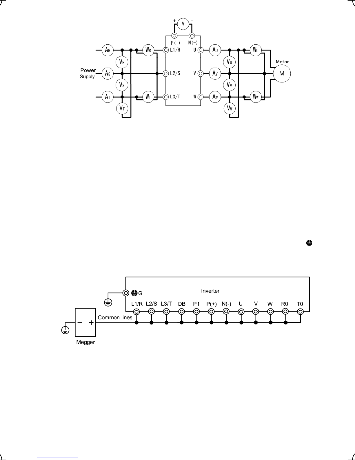
Figure 7.1 Connection of Meters
7.5 Insulation Test
Because an insulation test is made in the factory before shipment, avoid a Megger test.
If a Megger test is unavoidable, follow the procedure below. Because a wrong test procedure will cause breakage
of the inverter, take sufficient care.
A dielectric strength test will cause breakage of the inverter similarly to the Megger test if the test procedure is
wrong. When the dielectric strength test is necessary, contact your Fuji Electric representative.
(1) Megger test of main circuit
1) Use a 500 VDC Megger and shut off the main power supply without fail during measurement.
2) If the test voltage leaks to the control circuit due to the wiring, disconnect all the control wiring.
3) Connect the main circuit terminals with a common cable as shown in Figure 7.2.
4) The Megger test must be limited to across the common line of the main circuit and the ground terminal (
).
G
5) 5 MΩ (1 MΩ for the EMC filter built-in type of inverters) or a larger value displayed at the Megger indicates a
correct state. (The value is for a discrete inverter.)
Figure 7.2 Megger Test
(2) Dielectric strength test of control circuit
Do not perform a Megger test or dielectric strength test for the control circuit. Prepare a high resistance range
tester for the control circuit.
1) Disconnect all the external wiring from the control circuit terminals.
2) Perform a continuity test to the ground. 1 MΩ or a larger measurement indicates a correct state.
(3) Dielectric strength test of external main circuit and sequence control circuit
Disconnect all the inverter terminals so that the test voltage is not applied.
7-6
Page 90

7.6 Inquiries about Product and Guarantee
(1) When making an inquiry
Upon breakage of the product, uncertainties, failure or inquiries, report the following information to your Fuji
Electric representative.
1) Inverter type (Refer to Chapter 1, Section 1.1.)
2) SER No. (serial number of equipment) (Refer to Chapter 1, Section 1.1.)
3) Date of purchase
4) Inquiries (for example, point and extent of breakage, uncertainties, failure phenomena, and other
circumstances)
(2) Product warranty
The term of product warranty is one year after the purchase or 24 months from the month and year of production
specified on the nameplate, whichever comes first. However, the product will not be repaired free of charge in the
following cases, even if the warranty term has not expired.
1) The cause includes incorrect usage or inappropriate repair or modification.
2) The product is used outside the standard specified range.
3) The failure is caused by dropping, damage or breakage during transportation after the purchase.
4) The cause is earthquake, fire, storm or flood, lightening, excessive voltage, or other types of disaster or
secondary disasters.
7-7
Page 91
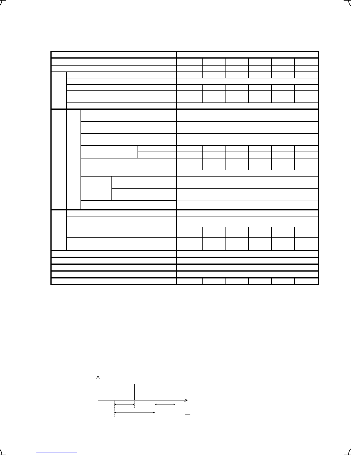
Chapter 8 SPECIFICATIONS
8.1 Standard Models
8.1.1 Three-phase 200 V class series
Item Specifications
Type FRN___LM1S-2_
Nominal applied motor *1 [kW] 5.5 7.5 11 15 18.5 22
Rated capacity *2 [kVA] 10.2 14 18 24 28 34
Rated voltage *3 [V] Three-phase 200V-240V,50/60Hz
Rated current *4 [A] 27.0 37.0 49.0 63.0 74.0 90.0
Overload capacity [A]
(Permissible energizing time)
Output ratings
Rated frequency [Hz] 50, 60Hz
Main power supply
Phases,Voltage,Frequency
Auxiliary control power input
Phases,Voltage,Frequency
Voltage/frequency variations
Rated current *6 [A]
Normal operation
Required power supply capacity *7
Input ratings
[kVA]
Main power supply
Auxiliary
control
power
*12
input
Battery
operation
Operation time
Braking time
*14
Braking duty-cycle (%ED)
Rated regenerative power
Braking
Minimum resistance which can be connected
*9
[Ω]
DC Reactor (DCR) Option
Applicable safety standard
Enclosure (IEC60529) IP20
Cooling method Fan cooling
Weight/Mass [kg] 5.7 5.9 7.4 11.0 11.3 11.8
*1) Fuji’s 4-pole standard motor
*2) Rated capacity is calculated by regarding the output rated voltage as 220V for three-phase 200V series.
*3) Output voltage cannot exceed the power supply voltage.
*4) It is a value in the condition of the career frequency 10kHz and the ambient temperature 45°C. Select the inverter capacity such that the square average
current in cycle operation is 80% or less of the rated current of an inverter.
*5) Voltage unbalance [%]
*6) The power supply capacity is 500kVA (ten times the inverter capacity when the inverter capacity exceeds 50kVA), and the calculation value when
connecting with the power supply of %X=5%.
*7) Obtained when a DC Reactor is used.
*8) An acceptable variation of the main power supply and the control power supply assistance input.
*9) The admissible error of minimum resistance is ±5%.
*10) Type List
A box () in the above table replaces C, E, A or J depending on the shipping destination.
A bo x () in the above table replaces A for the inverter without a CAN port
*12) The same AC power as the m ain power supply input is connected for the backup of the control circuit power source.
*13) It is a value in the condition of the career frequency 10kHz and the ambient temperature 45°C. Use the inverter such that the square average current in
battery operation is 80% or less of the rated current of an inverter.
*14) Braking time and duty cycle (%ED) are defined by cycle operation at the rated regenerative power as shown in the figure below.
=
Regenerative power [kW]
*10
5.5 7.5 11 15 18.5 22
54.0
(10s)
74.0
(10s)
98.0
(10s)
Three-phase, 200 to 240V, 50/60Hz
*12
*8
Single-phase, 200 to 240V, 50/60Hz
Voltage: +10 to -15% (Voltage unbalance: 2% or less
Frequency: +5 to -5%
with DCR 21.1 28.8 42.2 57.6 71.0 84.4
without DCR 31.5 42.7 60.7 80.1 97.0 112
7.4 10 15 20 25 30
DC 24V or more in the direct current voltage conversion.
Phases, Voltage,
Frequency
Voltage/frequency
variations
*13
[s] 180
Single-phase, 200 to 240V, 50/60Hz
Voltage: +10 to -15%, Frequency: +5 to -5%
[s] 60
*14
[%] 50
*14
[kW] 4.4 6.0 8.8 12 14.8 17.6
15 10 7.5 6 4 3.5
(Max. voltage [V] - Min. voltage [V])/ Three-phase average voltage [V] x 67 (IEC61800-3)
EN61800-5-1:2003, EN954-1 Category3
126.0
(10s)
*15
148.0
(10s)
180.0
(5s)
*5
),
Reated regenerative power
0
Braking time : T
*15) The inverter that last 2 digits of a software version are from 50 to 99 corresponds to this standard.
1
Cyclic period :T
0
Braking time : T
Time [s]
1
T
1
%ED = ×100
T
0
8-1
Page 92

*10
*14
8.1.2 Three-phase 400 V class series
Item Specifications
Type FRN___LM1S-4_
Nominal applied motor *1 [kW] 3.7 5.5 7.5 11 15 18.5 22 30 37 45
Rated capacity *2 [kVA] 6.8 10.2 14 18 24 29 34 45 57 69
Rated voltage *3 [V] Three-phase 380V-480V, 50/60Hz
Rated current *4 [A] 9.0 13.5 18.5 24.5 32.0 39.0 45.0 60.0 75 91
Overload capacity [A]
(Permissible energizing time)
Output ratings
Rated frequency [Hz] 50, 60Hz
Main power supply
Phases,Voltage,Frequency
Auxiliary control power input
Phases,Voltage,Frequency
Voltage/frequency variations
Rated current *6
Normal operation
[A]
Required power supply capacity
[kVA]
Input ratings
*7
Main power supply DC 48V or more in the direct current voltage conversion.
Auxiliar
y
control
power
*12
input
Battery
operation
Braking time
Operation time
[s] 60
Braking duty-cycle (%ED)
Rated regenerative power
Braking
Minimum resistance which can be
connected [Ω] *9
DC Reactor (DCR) Option
Applicable safety standard
Enclosure (IEC60529) IP20 IP00
Cooling method Fan cooling
Weight/Mass [kg] 3.0 5.6 5.7 7.5 11.1 11.2 11.7 24 33 34
*1) Fuji’s 4-pole standard motor
*2) Rated capacity is calculated by regarding the output rated voltage as 440V for three-phase 400V series.
*3) Output voltage cannot exceed the power supply voltage.
*4) It is a value in the condition of the career frequency 10kHz and the ambient temperature 45°C. Select the inverter capacity such that the square average
current in cycle operation is 80% or less of the rated current of an inverter.
*5) Voltage unbalance [%]
*6) The power supply capacity is 500kVA (ten times the inverter capacity when the inverter capacity exceeds 50kVA), and the calculation value when
connecting with the power supply of %X=5%.
*7) Obtained when a DC Reactor is used.
*8) An acceptable variation of the main power supply and the control power supply assistance input.
*9) The admissible error of minimum resistance is ±5%.
*10) Type List A box () in the above table replaces C, E, A or J depending on the shipping destination.
*11) It is necessary to change the power-supply voltage change connector on the power supply printed wiring board depend on the power-supply voltage.
*12) 30kW or less
The inverter doesn't operate if the power supply is not input to the auxiliary control power input. Please supply power.
*13) It is a value in the condition of the career frequency 10kHz and the ambient temperature 45°C. Use the inverter such that the square average current in
battery operation is 80% or less of the rated current of an inverter.
*14) Braking time and duty cycle (%ED) are defined by cycle operation at the rated regenerative power as shown in the figure below.
A box () in the above table replaces A for the inverter without a CAN port
The same AC power as the main power supply input is connected for the backup of the control circuit power source.
37kW or more
The same AC power as the main power supply input is connected for the control circuit, the fan, and the contactor.
=
Regenerative power [kW]
4.0 5.5 7.5 11 15 18.5 22 30 37 45
18.0
(3s)
27.0
(10s)
37.0
(10s)
49.0
(10s)
64.0
(10s)
78.0
(10s)
Three-phase, 380 to 480V, 50/60Hz
*12
Single-phase, 200 to 480V, 50/60Hz
*8
Voltage: +10 to -15% (Voltage unbalance: 2% or less *5),
Frequency: +5 to -5%
with DCR 7.5 10.6 14.4 21.1 28.8 35.5 42.2 57.0 68.5 83.2
without
DCR
13 17.3 23.2 33 43.8 52.3 60.6 77.9 94.3 114
5.2 7.4 10 15 20 25 30 40 48 58
Phases,Voltage,Freq
uency
Voltage/frequency
variations
*13
[s] 180
*14
[%] 50
*14
[kW] 3.2 4.4 6.0 8.8 12 14.8 17.6 24 29.6 36
Single-phase, 200 to 480V, 50/60Hz
Voltage: +10 to -15%, Frequency: +5 to -5%
96 64 48 24 24 16 16 10 10 8
(Max. voltage [V] - Min. voltage [V])/ Three-phase average voltage [V] x 67 (IEC61800-3)
EN61800-5-1:2003, EN954-1 Category3
*15
90.0
(10s)
Three-phase
380V-460V,50/60Hz
108
(5s)
135
(5s)
163
(5s)
Single-phase,
380 to 480V,
*11
50/60Hz
Single-phase,
380 to 480V,
*11
50/60Hz
EN61800-51:2003
Reated regenerative power
0
Braking time : T
Cyclic period :T
*15) The inverter that last 2 digits of a software version are from 50 to 99 corresponds to this standard.
Time [s]
0
Braking time : T
1
T
1
%ED = ×100
T
0
1
8-2
Page 93

8.1.3 Single-phase 200 V class series
Item Specifications
Type FRN___LM1S-7 *9
Nominal applied motor *1 [kW] 2.2
Rated capacity *2 [kVA] 4.1
Rated voltage *3 [V] Three -phase 200V-220V, 50/60Hz
Rated current *4 [A] 11
Overload capacity [A]
(Permissible energizing time)
Output ratings
Rated frequency [Hz] 50, 60Hz
Main power supply
Phases,Voltage,Frequency
Auxiliary control power input
Phases,Voltage,Frequency
*10
Voltage/frequency variations*7 Voltage: +10 to -15% ,Frequency: +5 to -5%
Rated current *5 [A]
Normal operation
Required power supply capacity *6
Input ratings
Battery
Braking time
[kVA]
Main power supply DC 24V or more in the direct current voltage conversion.
Auxiliary
control
power
input
operation
Operation time
Phases,Voltage,Frequ
ency
Voltage/frequency
*10
variations
*11
*12
[s] 60
Braking duty-cycle (%ED)
Rated regenerative power
Braking
Minimum resistance which can be
connected [Ω]
DC Reactor (DCR) Option
Applicable safety standard
*8
with DCR 17.5
without DCR 24
[s] 180
*12
[%] 50
*12
[kW] 1.76
Enclosure (IEC60529) IP20
Cooling method Fan cooling
Weight/Mass [kg] 3.0
*1) Fuji’s 4-pole standard motor
*2) Rated capacity is calculated by regarding the output rated voltage as 220V.
*3) Output voltage cannot exceed the power supply voltage.
*4) It is a value in the condition of the career frequency 10kHz and the ambient temperature 45°C. Select the inverter capacity
such that the square average current in cycle operation is 80% or less of the rated current of an inverter.
*5) The power supply capacity is 500kVA (ten times the inverter capacity when the inverter capacity exceeds 50kVA), and the
calculation value when connecting with the power supply of %X=5%.
*6) Obtained when a DC Reactor is used.
*7) An acceptable variation of the main power supply and the control power supply assistance input.
*8) The admissible error of minimum resistance is ±5%.
*9) Type List A box () in the above table replaces C, E, A or J depending on the shipping destination.
A box () in the above table replaces A for the inverter without a CAN port
*10) The same AC power as the main power supply input is connected for the backup of the control circuit power source.
*11) It is a value in the condition of the career frequency 10kHz and the ambient temperature 45°C. Use the inverter such that the
square average current in battery operation is 80% or less of the rated current of an inverter.
*12) Braking time and duty cycle (%ED) are defined by cycle operation at the rated regenerative power as shown in the figure
below.
Regenerative power [kW]
2.2
22
(3s)
Single -phase, 200 to 240V, 50/60Hz
Single-phase, 200 to 240V, 50/60Hz
3.5
Single-phase, 200 to 240V, 50/60Hz
Voltage: +10 to -15%, Frequency: +5 to -5%
33
EN61800-5-1:2003, EN954-1 Category3
Reated regenerative power
0
Braking time : T
Cyclic period :T
Time [s]
0
Braking time : T
1
T
1
%ED = ×100
T
0
1
8-3
Page 94

8.2 Common Specifications
Item Description Remarks
Vector control with PG (for an asynchronous motor)
Control system
Max. speed
Controllable
range
Control
accuracy
Speed control
Setting
resolution
Start/stop
Vector control with PG (for a synchronous motor)
Torque vector control (Open loop control for an asynchronous motor)
120 Hz (3600 r/min for 4-pole motor) in the equivalent frequency
Pulse encoder frequency: 100 kHz max.
15 kHz or more recommended at the maximum speed
0 to 120 Hz (0 to 3600 r/min for 4 pole motor) in the equivalent frequency
Analog setting: ±0.2% of max. speed (ambient temp. within 25 ±10°C)
Multistep speed command/via-communications command:
Analog setting: 1/1000 of max. speed
Multistep speed command: 0.01 Hz in the equivalent inverter output frequency
Via-communications command: 1/20000 at the max. speed or 0.01 Hz (fixed) in
Terminal command: Run forward/reverse, coast-to-stop, external alarm, reset
alarm, etc.
Link operation: Operation by RS485 or CAN bus communications link
Key operation: Start and stop with
Note Before to proceed to running with these keys switch the mode from Remote
to Local using the multi-function keypad.
±0.01% of max. speed (ambient temp. within -10 to +50°C)
(99.99 Hz or less), 0.1 Hz (100.0 to 120.0 Hz)
the equivalent inverter output frequency
/
/
keys.
*1)
Data: Variable within 5 to 16 kHz
Carrier
frequency
Speed
command
Control facility
Features and
commands
Refer to Chapter 1, Section 1.4 "Storage Environment" and Chapter 2, Section 2.1 "Operating
Environment."
ment
Environ-
*1) Torque vector control is available from 4.0kW to 22kW of 400 V series. Please don’t use it with other products.
Note The carrier frequency may drop automatically according to the ambient
temperature or output current to protect the inverter. This protective operation
can be canceled by function code H98.
Multistep speed command source: Combination of 3 terminal command (8 steps)
Analog input
Link operation: Available for RS485 and CAN bus communications link.
Key operation: Can be set with / keys.
Note Before to proceed to running with these keys switch the mode from Remote
to Local using the multi-function keypad.
Operation Customizing feature
• Force to stop, Soft start
• Concurrent application of
S-curved accel./decel.
pattern + Accel./decel. time
+ Multistep frequency
commands
• Continue-to-run at the stop
frequency
• Torque control
• Creep-less operation
• Buttery drivable
• Unbalance load
compensation
Can be set with external voltage/current input.
• 0 to ±10 VDC/0 to ±100% (terminal [12], [V2])
• 4 to 20 mA DC/0 to 100% (terminal [C1])
• Run command/detected
speed assented timer
• Multistep speed
command/detected speed
assented timer
• Digital input/output logic
inversion
• Disable accel./decel.
Processing function
• Command source format
switching of the speed
controller
• Digital/analog torque biasing
8-4
• Feed-forward compensation
of the speed controller
• Oscillation suppression
observer
• Motor parameter tuning
• Magnet pole angle offset
tuning
• Password protection and
etc.
Miscellaneous
Page 95

8.3 Terminal Specifications
8.3.1 Terminal functions
For details about the main and control circuit terminals, refer to Chapter 2, Sections 2.3.6 and 2.3.7 (Table 2.12),
respectively.
8.3.2 Basic wiring diagram
(Note 8)
Power supply
Please refer to
8.1.1 or 8.1.2, 8.1.3
Aux.power input for
control circuits
Please refer to
8.1.1 or 8.1.2, 8.1.3
8-5
Page 96

(Note 1) When connecting a DC reactor (DCR), first remove the short bar between terminals P1 and P(+).
(Note 2) To protect wiring, insert a molded case circuit breaker (MCCB) or an earth leakage circuit breaker (ELCB) (with
overcurrent protection) of the type recommended for the inverter between the commercial power supply and the inverter.
Do not use a circuit breaker with a capacity exceeding the recommended capacity.
(Note 3) Connect this pair of wires to terminals [R0] and [T0] if you want the inverter to stay in standby state, with only its control
circuit being active, when the main circuit power supply is open (cut off). Without this pair of wires connected to these
terminals, you can still run the inverter as long as the main wires of the commercial power supply to the main circuit are
properly connected. Connect terminal [R0] and [T0] with the output side on earth leakage circuit breaker when you
connect earth leakage circuit breaker. When you connect terminal [R0] and [T0] with the input side of on earth leakage
circuit breaker, an earth leakage circuit breaker malfunctions. Connect insulation transformer or supplementary point of
contact B with the position shown in the figure below whenever you connect [R0] and [T0] with the input side of an earth
leakage circuit breaker.
Power
ELCB
Radio noise filter
Noise filter
Magnetic
contactor
Insulation
transforme r
or
Inverter
Magnetic contactor
supplementary point of contact B
(Note 4) For the wiring of the control circuit, use shielded or twisted wires. When using shielded wires, connect the shields to earth.
To prevent malfunction due to noise, keep the control circuit wires as far away as possible from the main circuit wires
(recommended distance: 10 cm or longer), and never put them in the same wire duct. Where a control circuit wire needs
to cross a main circuit wire, route them so that they meet at right angles.
(Note 5) Common terminals [11], [CM] and [CMY] for the control input/output circuits are insulated each other.
(Note 6) Use a shielded sheath cable to wire the control signals. Process and terminate correctly the shielded sheath ends
according to wiring state and specifications of the pulse encoder or host equipment. The figure in this section illustrates
an example for the cable’s shielded sheath grounding where the shielded sheath end is connected to the grounding wire
of the motor and another end is opened at the inverter side. If the inverter malfunctions due to noises picked up by
the signal cable, connecting the inverter end of the shielded sheath to the inverter’s [CM] terminal may reduce the noise
affection. When the wiring between the encoder and the inverter is long, the allophone and the torque ripple might be
generated because the signal from the encoder malfunctions by interfering with A phase and B phase. In this case,
please execute measures such as; wiring shorter cable, cable of smaller electrostatic capacity, etc.
(Note 7) A CAN port is provided on the FRNLM1S-C, -E, -A and -J, not on the FRNLM1S-EA, -AA or -JA.
(Note 8) Please connect it according to the drawing when you wire for the braking resistance. There is a possibility that charge
resistance and an inverter internal parts are damaged when miss wiring.
• Please connect it according to the drawing when you wire for the braking resistance.
Fire or accident could occur.
8-6
Page 97

8.4 External Dimensions
8.4.1 Standard models
Unit: mm
FRN2.2LM1S-7
FRN4.0LM1S-4
8-7
Page 98

Power
supply
voltage
Threephase
200 V
Type
FRN5.5LM1S-2
FRN7.5LM1S-2
FRN11LM1S-2
FRN15LM1S-2
FRN18.5LM1S-2
W W1 W2 W3 W4 H H1 D D1 D2 D3 D4 φA φB
220 196 63.5 46.5 46.5 260 238
250 226 67 58 58 400 378 85 130 166.2 2
Dimensions (mm)
215
118.5 96.5 136.7 21
34 42
FRN22LM1S-2
Threephase
400 V
FRN5.5LM1S-4
FRN7.5LM1S-4
FRN11LM1S-4
FRN15LM1S-4
FRN18.5LM1S-4
220 196 63.5 46.5 46.5 260 238
118.5 96.5 136.7 21
215
250 226 67 58 58 400 378 85 130 166.2 2
34 42
FRN22LM1S-4
Note: A box () in the above table replaces C (China), E (EU), A (Asia) or J (Japan) depending on the shipping
destination.
8-8
Page 99
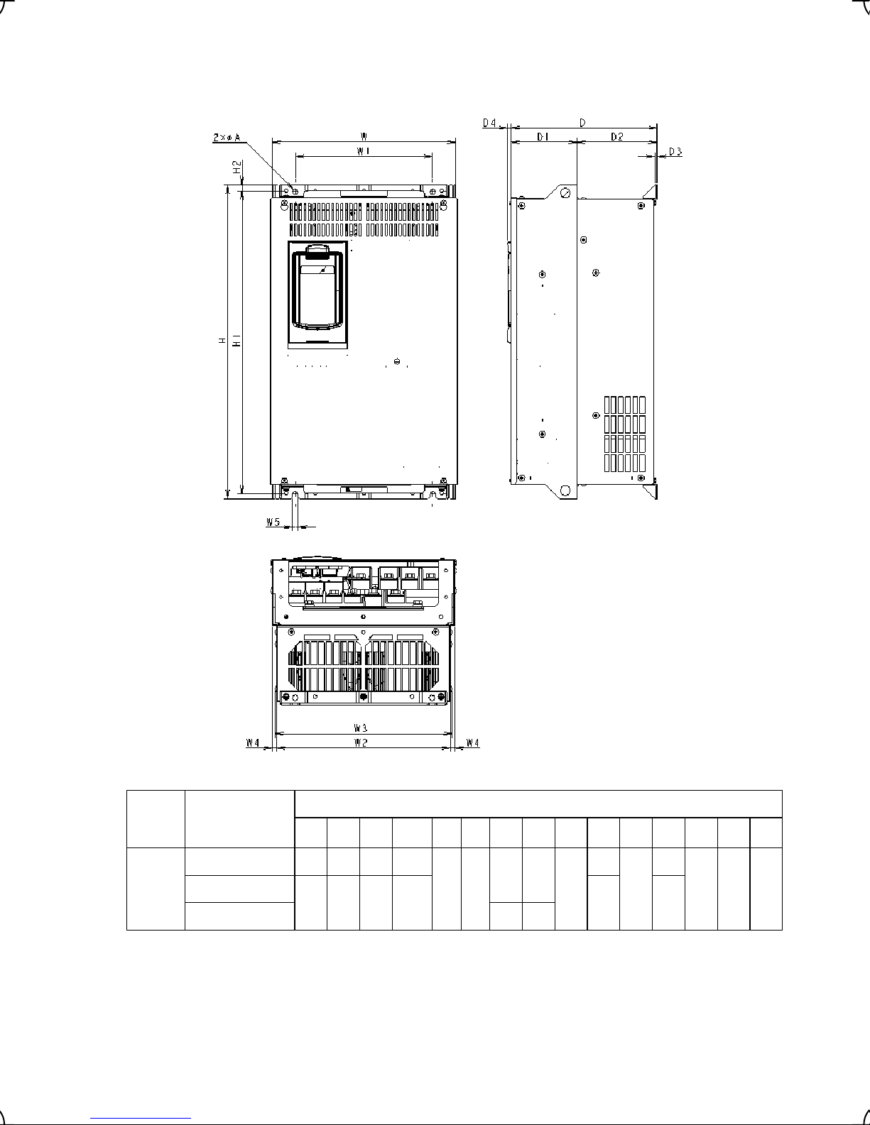
Unit: mm
Power
supply
voltage
Three-
phase
400 V
Note: A box (
destination.
Type
FRN30LM1S-4 320 240 304 310.2
FRN37LM1S-4
FRN45LM1S-4 615 595
) in the above table replaces C (China), E (EU), A (Asia) or J (Japan) depending on the shipping
Dimensions (mm)
W W1 W2 W3 W4 W5 H1 H1 H2 D D1 D2 D3 D4 φA
810
550 530
355 275 339 345.2 270 155
8-9
255
12
115
140
4 6 10
Page 100

8.5 Protection Features
Name Description
Overcurrent
protection
Short circuit
protection
Grounding
fault
protection
Overvoltage
protection
Undervoltage
protection
Input phase
loss protection
Overheating
protection
External alarm
input
The inverter is stopped for protection against overcurrent
caused by an overload.
The inverter is stopped for protection against overcurrent
caused by a short circuit in the output circuit.
The inverter is stopped for protection against overcurrent
caused by a grounding fault in the output circuit. If the power
supply is turned on with the grounding fault, the protection
may be invalidated.
An excessive voltage (400 VDC for the 200 V class series,
800 VDC for the 400 V class series) in the DC link circuit is
detected and the inverter is stopped. If a remarkably large
voltage is applied by mistake, the protection cannot be made.
Stops the inverter output when the DC link bus voltage drops below the
undervoltage level (200 VDC for the 200 V class series, 400 VDC for the 400 V
class series).
When the inverter is driven by a battery power, however, it disables an
undervoltage alarm detection and is to output no alarm signal.
Detects input phase loss, stopping the inverter output. This function prevents the
inverter from undergoing heavy stress that may be caused by input phase loss or
inter-phase voltage unbalance and may damage the inverter.
If connected load is light or a DC reactor is connected to the inverter, this function
will not detect input phase loss if any.
The temperature of the heat sink in the event of cooling fan trouble and overload
is detected to stop the inverter.
The temperature inside the inverter unit in the event of cooling fan trouble and
overload is detected to stop the inverter.
With the digital input signal THR, the inverter is stopped as for an alarm.
During
acceleration
During
deceleration
During running at
constant speed
During
acceleration
During
deceleration
During running at
constant speed
(Stopped)
LED
monitor
displays
*1
0c1
0c2
0c3
0u1
0u2
0u3
lu
lin
0h1
0h3
0h2
Alarm
output
[30A/B/C]
Yes
Yes
Yes*2
Yes*2
Yes
Yes
Ye s
Abnormal
condition in
charger circuit
Overload
protection
*1 When the inverter is equipped with the multi-function keypad, it displays the alarm letters on the LED indicator of the
keypad.
*2 This alarm [30A/B/C] may not be output depending upon the data setting of the function code.
Upon detection of an abnormal condition in the charger circuit inside the inverter,
this function stops the inverter output. (Applicable to 37 kW or above (3-phase
400 V))
The temperature inside the IGBT is calculated from the detection of output
current and internal temperature, to shut off the inverter output.
8-10
pbf
0lu
Yes
Yes
 Loading...