

Page 1
FCX SERIES
HAND HELD COMMUNICATOR
(HHC)
TYPE: FXW
INF-TN1FXWi-E
Instruction Manual
Page 2

– i –
INTRODUCTION
© Fuji Electric Co., Ltd. 1990
Issued in January, 1990
Rev. 6th edition June, 1999
Rev. 7th edition March, 2004
Rev. 8th edition June, 2009
Rev. 9th edition April, 2011
Manufacturer: Fuji Electric Co., Ltd.
Type: Described in nameplate on main frame (see Page iv)
Date of manufacture: Described in nameplate on main frame
Product nationality: Japan
Request
• Transcription of a part or the whole of this manual without
permission is prohibited.
• The contents of this manual are subject to change without
prior notice.
Thank you very much for your purchase of the Fuji Hand Held Communicator (HHC) (Type : FXW).
• First read this instruction manual carefully until an adequate understanding is required, and then pro-
ceed to connection and operation of the hand held communicator.
• The specications of the hand held communicator will be changed without prior notice for further
product improvement.
• Modication of the hand held communicator without permission is strictly prohibited. Fuji will not
bear any responsibility for a trouble caused by such a modication.
• This instruction manual should be kept by a person who is actually using the hand held communicator.
• After reading this manual, keep it at a place easier to access.
• This manual should be delivered to the end user without fail.
Export Precaution
This unit is not a strategic product (or service) prescribed by the foreign exchange and trade management
regulations, but is required to follow the restriction items of the regulations when it is to be exported.
Page 3
– ii –
CAUTION ON SAFETY
First of all, read this “Caution on Safety” to ensure correct operation of the Hand Held Communicator.
• The cautionary descriptions listed here contain important information about safety, so they should be ob-
served without fail. Those safety precautions are classied into ranks “DANGER” and “CAUTION”.
On items listed under “
CAUTION
”, they may also lead to serious accidents depending on circumstances, and
must be fully observed.
• The signs of prohibition and indication are explained in the following.
DANGER
CAUTION
Wrong handling may cause a dangerous situation, in which there is a
risk of death or heavy injury.
Wrong handling may invite a dangerous situation, in which there is a
possibility of medium-level trouble or slight injury or only physical
damage is predictable.
INDICATION
PROHIBITION
General items which pertain to prohibition (DO NOT)
General items which pertain to user's action
Maintenance / Inspection
DANGER
• Do not attempt to charge the battery in hazardous area.
• Do not attempt to replace the battery in hazardous area.
CAUTION
Operation I & II
• When changing set values, make sure that the control loop is in the manual mode.
Connection
DANGER
• Non-explosion-proof HHC must not be used in hazardous area to prevent serious accidents such as
explosion, re, etc.
• When using a ame-proof transmitter, do not connect HHC to the transmitter terminals and junction
terminals in hazardous area.
Page 4

– iii –
Page
INTRODUCTION ........................................................................................................................ i
CAUTION ON SAFETY ..............................................................................................................ii
1. GENERAL .............................................................................................................................1-1
2. PRODUCT CHECK ...............................................................................................................2-1
3. OPERATING PARTS AND DESCRIPTIONS ......................................................................3-1
3.1 Name and description ................................................................................................................. 3-1
3.2 Descriptions of operating parts ................................................................................................... 3-2
4. CONNECTION ......................................................................................................................4-1
4.1 Connection of HHC .................................................................................................................... 4-1
4.2 Power supply and load resistance ............................................................................................... 4-2
5. OPERATION (FOR TRANSMITTER) .................................................................................5-1
5.1 Descriptions of displays ............................................................................................................. 5-2
5.2 Operating procedures .................................................................................................................. 5-2
5.3 Outline of HHC operation .......................................................................................................... 5-3
5.4 Operating procedures .................................................................................................................. 5-4
5.5 Printout format for smart transmitter .......................................................................................... 5-26
5.6 Printer paper feed function ......................................................................................................... 5-27
6. ABNORMAL DISPLAY AND COUNTERMEASURE .......................................................6-1
7. MAINTENANCE AND INSPECTION .................................................................................7-1
7.1 Battery charging ......................................................................................................................... 7-1
7.2 Battery replacement .................................................................................................................... 7-2
APPENDIX
1. SPECIFICATION SHEET .....................................................................................................A-1
2. HAZARDOUS LOCATION INSTALLATION INFORMATION ........................................A-7
3. SETTING OF PRINTER ROLL PAPER ...............................................................................A-14
4. PARTS LIST ...........................................................................................................................A-15
CONTENTS
Page 5

– iv –
CONFIRMATION OF TYPE OF UNIT
Hand Held Communicator
TYPE FXW
Power Supply
DC1.2Vx5 600mAh
Ser. No.
Mfd. TK
Fuji Electric Co., Ltd.
Made in Japan
The following items are shown in this nameplate.
Type: Type of unit
Power supply: Power source (nickel-cadmium battery) specications
Ser. No.: Work No.
Mfd: Date of manufacture
Instrument nameplate shown below is attached to the rear panel of the unit. Before using the unit, be sure to
conrm the code symbols and specications.
Page 6

1 - 1
This instrument is designed for use with each smart type device of FCX series transmitter.
Setting changes and adjustments necessary for operation of each device can easily be made during communi-
cations with operator.
Applicable eld devices
(1) FCX series transmitter
• Differential pressure/ow transmitter (FKC)
• Pressure transmitter (FKG)
• Absolute pressure transmitter (FKA)
• Level transmitter (FKE)
• Remote seal type differential pressure transmitter (FKD)
• Remote seal type pressure transmitter (FKB)
(2) FCX-A series transmitter
• Differential pressure/ow transmitter (FKC ... 2)
• Pressure transmitter (FKG ... 2)
• Absolute pressure transmitter (FKA ... 2)
• Level transmitter (FKE ... 2)
• Remote seal type differential pressure transmitter (FKD ... 2)
• Remote seal type pressure transmitter (FKB ... 2)
• Small ange level transmitter (FKY ... 2)
• Small ange remote seal type differential pressure transmitter (FKX ... 2)
• Small ange remote seal type pressure transmitter (FKW ... 2)
(3) FCX-C series transmitter
• Differential pressure/ow transmitter (FKK)
• Pressure transmitter (FKP)
• Absolute pressure transmitter (FKH)
(4) FCX-AX series transmitter
• Differential pressure/ow transmitter (FKC... 3)
• Pressure transmitter (FKG... 3)
• Absolute pressure transmitter (FKA... 3)
• Level transmitter (FKE... 3)
• Remote seal type differential pressure transmitter (FKD... 3)
• Remote seal type pressure transmitter (FKB... 3)
• Small ange level transmitter (FKY ... 3)
• Small ange remote seal type differential pressure transmitter (FKX ... 3)
• Small ange remote seal type pressure transmitter (FKW ... 3)
1. GENERAL
Page 7

1 - 2
(5) FCX-AII series transmitter
• Differential pressure/ow transmitter (FKC ... 4)
• Pressure transmitter (FKG ... 4)
• Absolute pressure transmitter (FKA ... 4)
• Level transmitter (FKE ... 4)
• Remote seal type differential pressure transmitter (FKD ... 4)
• Remote seal type pressure transmitter (FKB ... 4)
• Small ange level transmitter (FKY ... 4)
• Small ange remote seal type differential pressure transmitter (FKX ... 4)
• Small ange remote seal type pressure transmitter (FKW ... 4)
(6) FCX-CII series transmitter
• Differential pressure/ow transmitter (FKK ... 4)
• Pressure transmitter (FKP ... 4)
• Absolute pressure transmitter (FKH ... 4)
(7) FCX-AIII series transmitter
• Differential pressure/ow transmitter (FKC ... 5)
• Pressure transmitter (FKG ... 5)
• Absolute pressure transmitter (FKA ... 5)
• Level transmitter (FKE ... 5)
• Remote seal type differential pressure transmitter (FKD ... 5)
• Remote seal type pressure transmitter (FKB ... 5)
• Small ange level transmitter (FKY ... 5)
• Small ange remote seal type differential pressure transmitter (FKX ... 5)
• Small ange remote seal type pressure transmitter (FKW ... 5)
• Pressure transmitter (Direct mount type) (FKP ... 5)
• Absolute pressure transmitter (Direct mount type) (FKH ... 5)
Page 8
2 - 1
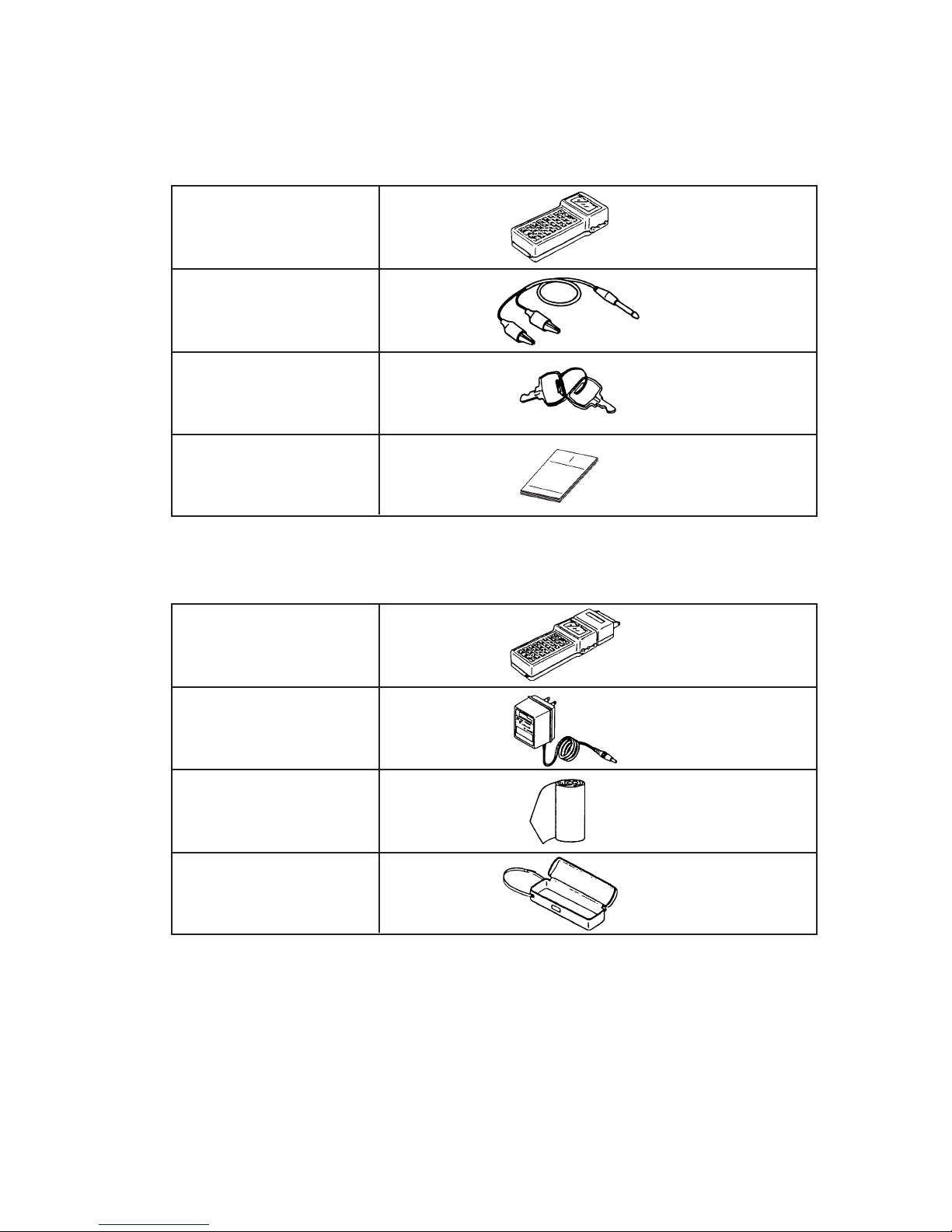
Check to make sure that the following products are included.
2. PRODUCT CHECK
Option
HHC
(without printer)
Communication cable
(about 1 m)
Security key (2 pcs)
Instruction manual
HHC with printer
Battery charger
Roll paper
Carrying case
Page 9
3 - 1
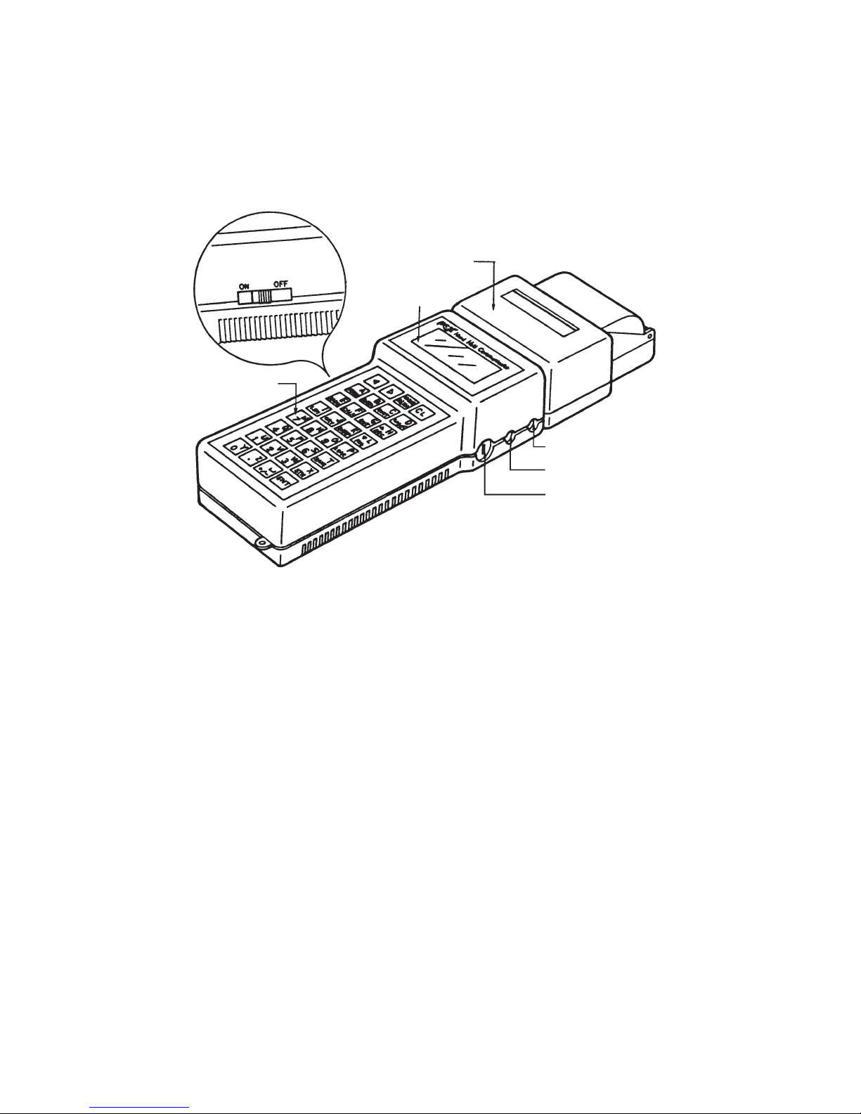
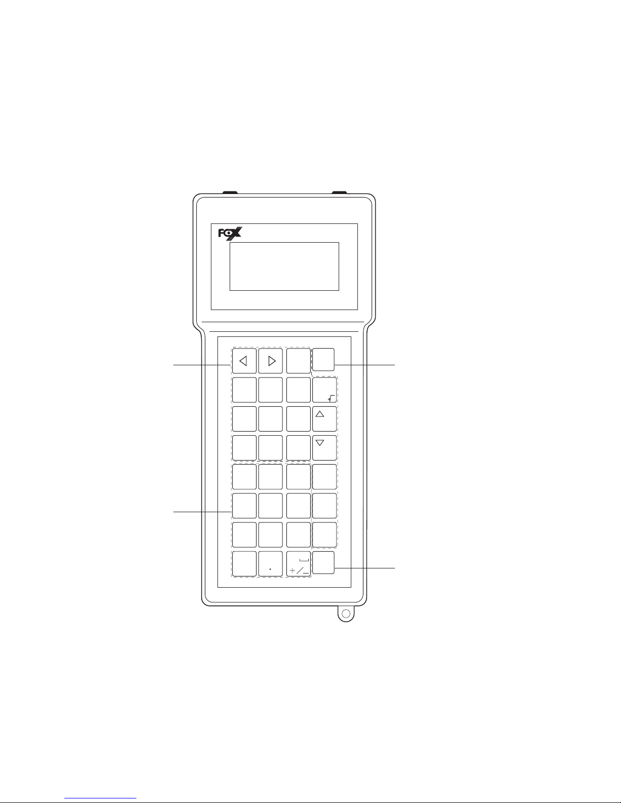
3.1 Name and description
3. OPERATING PARTS AND DESCRIPTIONS
* Battery charger terminal:
Used to charge battery by using a special battery charger.
* Communication cable terminal:
Used to connect communication cable.
* Security key socket:
Used to connect security key.
* Display unit:
Displays data and set values.
* Printer (option):
Prints data and set values.
* ON/OFF switch:
Power ON/OFF switch
Battery charger terminal
Communication cable terminal
Security key socket
Printer (option)
Display unit
ON/OFF switch
Keyboard
Page 10
3 - 2
3.2 Descriptions of operating parts
The operating unit contains 4 kinds of keys; command keys (blue), numeric keys (yellow), ENT key
(red) and CL key (green). For the function of these keys, please refer to “5. Operation”.
Hand Held Communicator
0
Y
Z
1U2
V
3
W
X
4Q5
R6S
SAVE
T
7M8
N9O
LOAD
P
I J
DAMP
K L
E F G H
A B
U N IT
C D
MENU DATA LIN/
CHNG
AL HA
RANG
CA LB
C L
DECOU T
L R V
URV
I N C
S T N
E N T
Command Keys
Select function
Numeric Keys
Clear Key
ENT Key
Used to send information
to field device.
Page 11
4 - 1
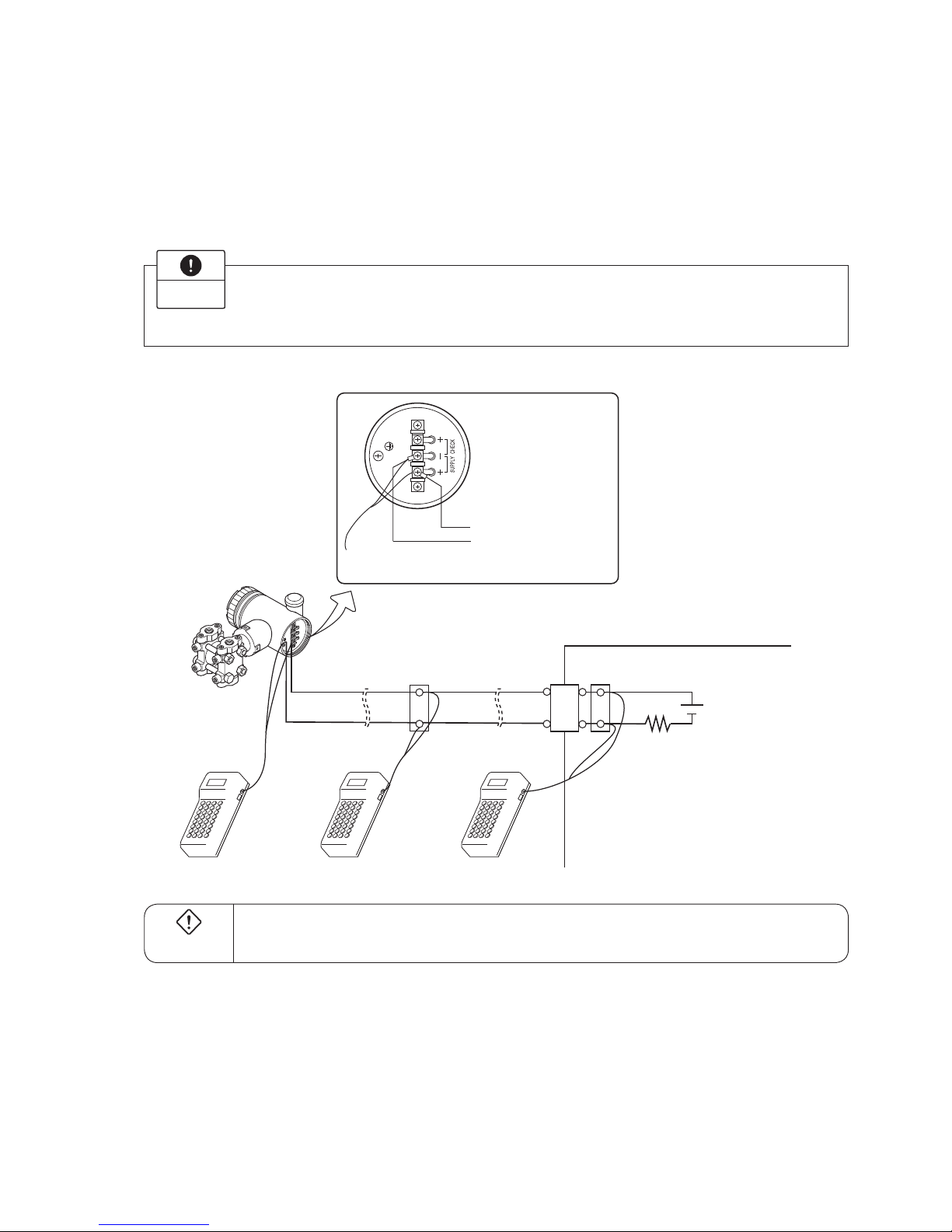
4.1 Connection of HHC
Connect HHC in parallel with the current output of a eld device.
4. CONNECTION
Instrument room
Terminal block
DC power supply
Load resistor
250 or more
Refer to “4.2 Power supply and
load resistance”.
Junction terminal Zener barrier
Field device
To junction terminal
or instrument room
HHC
(Connect to transmitter "+" and "–" terminals)
1. Connect HHC after holding the transmitter ON for about 10 seconds.
2. When connecting HHC, ensure ON/OFF switch is in the OFF position.
3. HHC communication cable has no polarity.
Impor t ant
In the case of a ameproof transmitter, never connect the HHC to the terminal block of the
transmitter in hazardous area installations.
DANGER
Page 12
4 - 2
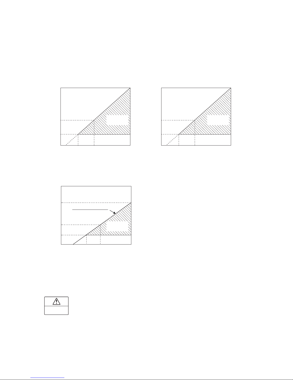
4.2 Power supply and load resistance
When using HHC, the output load resistance of the transmitter should be within the range shown in
Fig. 4-1. (for transmitter)
Fig. 4-1
1511
0
11
16.6 24 45 (V)
578
250
Operating
range zone
1533
0
10.5
16.1 24 45 (V)
600
250
(Ω)(Ω)
(Ω)
Load resistanceLoad resistance
Load resistance
Power voltage Power voltage
(a) FCX transmitter
When lmax is 22.5mA
(b) FCX-A/C transmitter, FCX-AX transmisster
and FCX-AII/CII transmitter
(c) FCX-AII/CII series transmitter (software version 4.06, amplifier revision 4FA)
and FCX-AIII series transmitter
Operating
range zone
45(V)
2410.5
16.35
250
1474
577
Power supplay voltageE (DC)
E - 10.5
(Imax+0.9)×10
-3
R=
Note) Imax is the bigger one, either upper saturation
current [mA] or upper burnout current [mA].
When Imax is from 20mA to 21.6mA, calculate load
resistance using Imax of 21.6mA.
And when Imax is from 21.7mA to 22.5mA, calculate
load resistance using the formula in the figure.
Operating
range zone
CAUTION
The transmitter of intrinsic safety explosion-proof type has some limitations of supply voltage and
load resistance in accordance with the safety barrier used in combination, installation of the transmit-
ter, cable work and grounding work. Refer also to the instruction manual of the targeted transmitter
for details.
Page 13

5 - 1
Cautions prior to operation
5. OPERATION (FOR TRANSMITTER)
Common operation for all displays
* If the selected display is incorrect, press the
C L
key to return to the previous display.
If the alphanumeric display is incorrect, move the cursor to the point to be changed by pressing the
or
key and reset it.
* When setting alphacharacters rst press the
CHNG
AL HA
key, then press an alphacharacters key.
Alphacharacters cannot be set continuously.
Press the
CHNG
AL HA
key each time.
* When the
E NT
key is pressed at the completion of an operation, the information is transmitted to the
eld device.
Cautions during operation
When the security key is in the OFF position, no changes can be make to the field device.
Impor t ant
When changing a set value, make sure the control loop is in manual mode.
DANGER
1. Turn ON the power switch. If the battery alarm is displayed, the battery should be
charged.
2. If standby indication is displayed before operation, press the
C L
key.
Impor t ant
Page 14
5 - 2
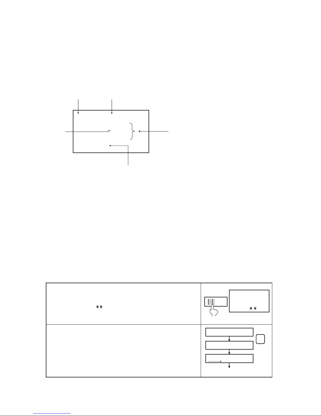
5.1 Descriptions of displays
Transmitter information can easily be checked and changed via the HHC using the messages shown on
the display.
The display is a liquid crystal type shown the following contents in 4 lines with 16 characters.
6-2 : RANGE CHANGE
L
RV ±XXX. XmmH2O
URV ±XXX. XmmH
2
O
<ENT> <CL>
Data section
FunctionMenu No.
Cursor
Prompts (keys to take operator to next display)
The meaning of the prompts are as follows.
<ENT> : The contents displayed in the data section are
inputted to the field device.
<INC> : The cursor moves to the next option in the menu.
<CHANGE> : The cursor moves to the lower display to change
the data shown in the data section.
<CL> : The inputted data is cleared according to the data
section and the previous data display.
There are a total of 18 menu options, from No. 1 to I.
5.2 Operating procedures
Check the instrument for correct wiring and operate it according to the following procedures.
(See “4. Connection, 4.1”)
FCX SMART FAMILY
HANDHELD
COMMUNICATOR
VERSION .
RECEIVING START
RECEIVING START
TAG NO Display
MENU
ON OFF
PUSH MENU KEY
The image shown at right is displayed when the power switch turns ON.
(FXW program version is displyed for about 3 seconds after the power is
ON.)
The HHC of version 6. or later does not support the electromagnetic
flowmeter (type FMQ/FMT).
In this case, contact our office to replace the versions of FXW ROM.
When the printer is not connected to the HHC, “Push MENU KEY” is
displayed after the software version is displayed. When the printer is
connected to the HHC, please refer to the item 5.4.
By pressing the MENU key “RECEIVING START” is displayed.
The number of broken line arrow marks increases according to the data
received. Next “TAG NO.” display is shown, press the key symbols
shown in the following table to display setting items.
Page 15
5 - 3
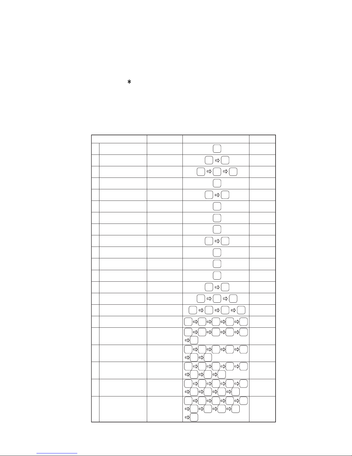
5.3 Outline of HHC operation
The following shows the ow of key operations, explained for FXW version 7.1 (FXW
1-
3).
FXW prior to version 5. (FXW
1-
2) are not available of operation of FCX-AII/CII series
transmitter and FCX-AIII series transmitter.
In this case, contact our ofce for ROM version up.
A part of the operation of the HHC of version 7.0 or earlier may differ or some items may not be set if
the HHC is used for FCX series, FCX-A/C series, FCX-AX series transmitter or FCX-AII/CII series
transmitter.
Classification Display symbol Key operation
Referential
page
1
2
3
4
5
6
7
8
9
A
B
C
D
E
F
G
H
I
TAG No.
Type
Display of serial No.
Industrial value unit
Range limit
Range change
(LRV,URV)
Damping adjustment
Output mode and value
Burnout direction
Zero/span adjustment
Calibration of output circuit
Indication of measured data
Self-diagnosis
Printer function
Lock of adjustment
functions
Indication of digital
indicat
Programmable linearization
function
Rerange
(Set LRV/URV calibration)
1: TAG No.
2: TYPE
3: SERIAL No.
4: UNIT
5: RANGE LIMIT
6: RANGE
7: DAMPING
8:
OUTPUT MODE
9: BURNOUT
A: CALIBRATE
B: OUTPUT ADJ
C: DATA
D: SELF CHECK
E: PRINT
F:
XMTR EXT. SW
G: XMTR DISPLAY
H: LINEARIZE
I: RERANGE
5-4
5-5
5-5
5-6
5-7
5-7
5-8
5-9
5-10
5-11
5-12
5-13
5-13 to 5-14
5-14
5-15
5-16 to 5-18
5-19 to 5-20
5-21
INC INC
INC
INCDATA INC INC INC
INC INC INCDATA INC
INCDATA INC INC INC
MENU
MENU
INC
MENU INC INC
UNIT
INC
UNIT
RANG
DAMP
LIN
/ √
LIN
/ √
INC
CALB
OUT
DATA
INCDATA
INC INCDATA
INC INC INCDATA
J
Saturation current value
and specification
J: SATURATE CUR
5-22
INC INC
INCDATA INC INC INC
INC
K
Write protect
K: WRITE PROTCT
5-23 to 5-24
INC INC
INCDATA INC INC INC
INC INC
L
History information
L: HISTORY 5-25
INC INC
INCDATA INC INC INC
INC
INC INC
Page 16
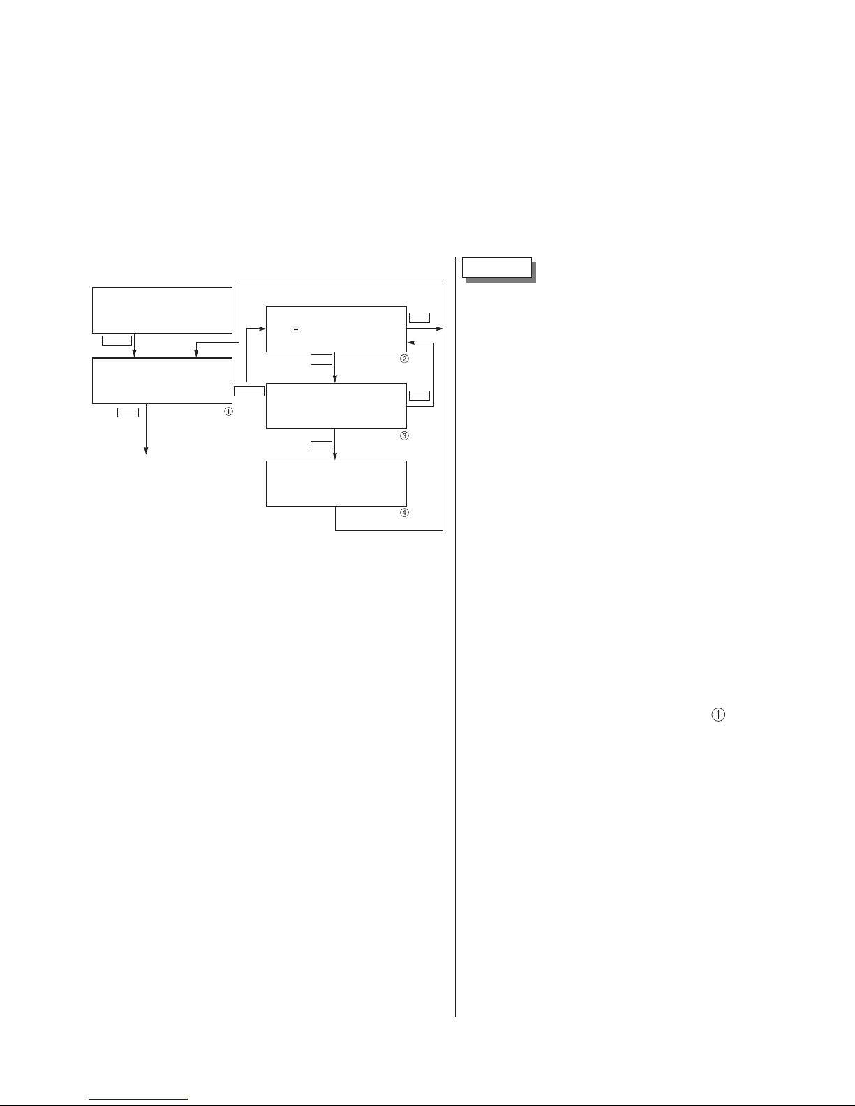
5 - 4
TAG NO.
To set the TAG NO. of each eld device,
use the procedures shown in the following
diagram. TAG NO. can be inputted up to
26 character of alphanumeric codes.
• After PUSH MENU KEY is displayed,
press the <MENU> key to display TAG
NO.
• To make changes press the <CHNG> key
and the cursor will be displayed under
display①.
• Set the alphanumeric keys as necessary
under display②.
To set the alphabet, press the <CHNG
ALHA> key rst.
Using <v><u> keys, cursor position can
be moved.
• At the completion of setting, press the
<ENT> key and a prompt is displayed
check entry under display②.
• If the entry is correct, press the <ENT>
key to input it to the field device under
display③and④and the initial image
is displayed.
• To di splay TYPE dis p lay, pr ess the
<INC> key under display①.
5.4 Operating procedure
The following shows the operating procedure of HHC connecting to FCX-AIII series transmitter.
A part of the operation of the HHC of version 7.0 or earlier may differ or some items may not be set if
the HHC is used for FCX series, FCX-A/C series, FCX-AX series transmitter or FCX-AII/CII series
transmitter.
1: TAG No
FICRA-1234
× × × × ×
× × × × × × × × × × ×
< INC > < CHANGE >
1-1: TAG CHANGE
FICRA-1234
× × × × ×
× × × × × × × × × × ×
< ENT > < CL >
1-1: TAG CHANGE
FICRA-4321
× × × × ×
× × × × × × × × × × ×
CHNG OK?< ENT/CL >
1-2: TAG WRITE
FICRA-4321
× × × × ×
× × × × × × × × × × ×
To TYPE SETTING image
0: PUSH MENU KEY
CL
INC
CHNG
MENU
CL
ENT
ENT
after setting
Page 17

5 - 5
2: TYPE
FKCS35V5-AAAYY-
AA
< INC > < CHANGE >
2-1: TYPE CHANGE
FKCS35V5-AAAYY-
AA
< ENT > < CL >
2-1: TYPE CHANGE
FKCS35V5-AAAYY-
AA
CHNG OK?< ENT/CL >
2-2: TYPE WRITE
FKCS35V5-AAAYY-
AA
To SERIAL No.display
TAG No.
CL
INC
INC
CHNG
CL
ENT
ENT
after setting
3: SERIAL No.
N8G07131
VERSION 5.15
< INC >
To UNIT setting image
TYPE
INC
INC
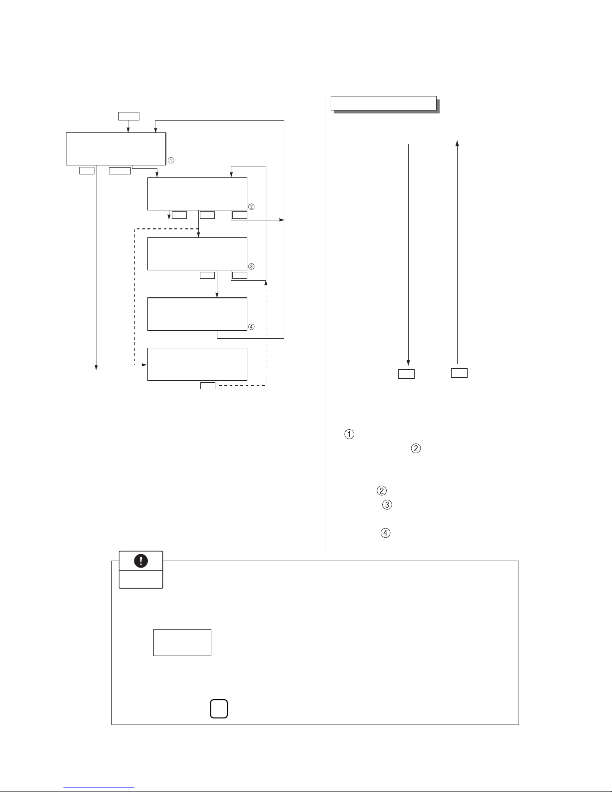
Display of SERIAL NO.
SERIAL NO. and transmitters software
version are displayed.
• After setting TYPE, press the <INC> key
to display SERIAL NO. and software version of transmitter.
• By pressing the <INC> key, UNIT setting
image is displayed.
TYPE
Type of fiel d devi ce i s disp laye d and
changed (example of differential pressure
transmitter).
• After TAG NO. is displayed, press the
<INC> key to display TYPE image.
• To make changes press the <CHNG> key
under display①and the cursor will be
displayed under display②.
• Set the alphanumeric keys as necessary
under display②.
To set the alphabet, press the <CHNG
ALHA> key rst.
Using <><> keys, cursor position can
be moved.
• At the completion of setting, press the
<ENT> key and a prompt is displayed
check entry under display②.
• If the entry is correct, press the <ENT>
key to input it to the field device under
display③and④and the initial image①
is displayed.
• To d i splay SE R I A L NO . , pres s the
<INC> key under display①.
Page 18
5 - 6
< UNIT CHANG >
4-1: UNIT CHANGE
kPa
< INC > < ENT > < CL >
4-1: UNIT CHANGE
CHNG OK? < ENT/CL >
4-1: UNIT WRITE
< INC >
4: UNIT
MENU NO. 5
kPa
< CHNG >
(NEXT MPa)
(NEXT MPa)
kPa
kPa
4-1: UNIT WRITE
UNIT < CL >
NOT SUITABLE
Not suitable unit display
Pa
UNIT
CL
CL
CL
INC
INC
CHNG
ENT
ENT
DEC
INC
mmH O
2
cmH O
2
mH O
2
g/cm
2
Pa
inH O
2
psi
ftH O
2
< Torr >
kg/cm
2
< atm >
hPa
kPa
MPa
mbar
bar
mmAq
mmHg
cmAq
mAq
mmWC
cmWC
mWC
inHg
cmHg
mHg
Note: The mark < > is settable for absolute
pressure transmitter only.
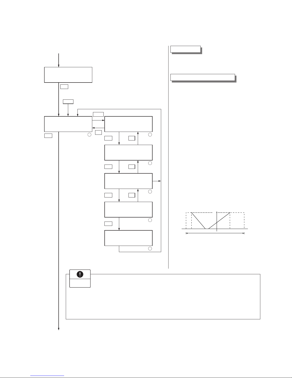
• When pressing <CHNG> under display
,
the display for changing the unit of
industrial value
appears.
• The desired unit of industrial value is selectable by using <INC> or <DEC> under
display
.
• Display
is provided for confirming
your change.
• Display
is for registering the unit of
industrial value.
Impor t ant
The unit of industrial value is set according to the range as ordered, but the display resolution
lowers depending on the unit being set.
When
is displayed upon changing the unit of industrial value, output cannot be displayed in the engineering unit selected.
4-1:UNIT CHANGE
Pa
NOT SUITABLE
UNIT <CL>
In this case, press the
C L
key and change the engineering unit to a different one.
Industrial value unit
Available unit for FCX-AII/CII and FCXAIII
Page 19
5 - 7
INC
RANG
INC
CL
CHNG
LRV
CL
URV
CL
ENT
CL
ENT
6-3: RANGE WRITE
6-1: RANGE CHANGE
LRV
× × × . ×
kPa
< LRV > < URV > < CL >
URV
× × × . ×
kPa
LRV
× × × . ×
kPa
< LRV > < URV > < CL >
URV
× × × . ×
kPa
LRV
× × × . ×
kPa
< LRV > < URV > < CL >
URV
× × × . ×
kPa
LRV
× × × . ×
kPa
URV
× × × . ×
kPa
LRV
× × × . ×
kPa
URV
× × × . ×
kPa
2
6-2: RANGE CHANGE
3
6-2: RANGE CHANGE
4
CHNG OK? < ENT/CL >
6-2: RANGE CHANGE
5
6
1
6: RANGE
LRV
× × × . ×
kPa
< INC > < CHANGE >
5: RANGE LIMIT
× × ×
kPa
< INC >
URV
× × × . ×
kPa
Output (mA)
URV
Maximum measuring range
Input
Normal
action
Reverse
action
4
LRV LRV URV
20
Impor t ant
In case of the actual scale specication with a digital indicator provided, if the
range is changed, indicator display does not match. So, setting is required again
in response to the display in the digital indicator (G: XMTR DISPLAY). In case
of the actual scale specication with an analog indicator provided, if the range is
changed, indicator display does not match. So, replacement of the analog indicator is required.
Range limit
Indicates the maximum measuring range of
this transmitter.
Range change (LRV, URV)
LRV: Lower range value (0% point)
URV: Upper range value (100% point)
• When pressing <CHNG> under display
①
, display changes to the LRV and URV
selection screen.
Press <LRV> for presenting the display
for setting the zero point range (display
③
), or <URV> for presenting the display
for setting the span range (display ④).
• Under displays③and ④, input zero
point and span values.
*Press <E NT> aft er setti ng LRV an d
URV.
• When pressing <+/–> under display ③,
④
, negative value is available.
Selectable setting range
Page 20

5 - 8
CHNG
DAMP
ENT
CL
7: DAMPING
0.3SEC
< INC >
2
ENT
< CHANGE >
CL
1
7-1: DAMP CHANGE
after
setting
0.3SEC
< INC >
7-1: DAMP CHANGE
1.2SEC
CHNG OK? < ENT/CL >
3
7-2: DAMP WRITE
1.2SEC
4
< ENT > < CL >
INC
About the output uctuation of the transmitter caused by vibration and damping
1) Magnitude of output uctuation (oscillation) caused by vibration
If the transmitter is mounted to a place subject to severe vibration, output uctuation (oscillation) may increase. Since the transmitter uses oil as internal pressure transmitting medium,
if acceleration is caused by vibration, internal pressure is generated in accordance with the
acceleration value, thus resulting in the output uctuation. The magnitude of output oscillation may become the value shown below at the maximum.
Oscillation frequency: 10 to 150 Hz
Within ±0.25% of URL/(9.8m/s2)
2) Damping
The output uctuation (oscillation) of the transmitter in an environment subject to vibration
can be damped by setting appropriate damping time constant using the HHC. The following
table shows the effect of damping on the vibration of 10Hz where the output uctuation
becomes the maximum.
Guideline of the effect of damping on the output uctuation (oscillation)
Damping set value [sec] Damping of output oscillation Remarks
1.2 1/3 or lower
4.8 1/5 or lower
19.2 1/10 or lower
Note) In the oscillation range from 10 to 150Hz, the output uctuation (oscillation)
becomes the maximum at 10Hz, that is, the lowest frequency.
Damping adjustment
In the case where the process input uctuation is large, the vibration of the installation site is large, and minute differential
pressure is measured, if the output uctuation is large, set appropriate damping time
constant to suppress the output uctuation.
Input time constant value under display②,
time constant can be changed.
Selectable time constant value:
0.12 to 32 sec (FCX-AII/CII series transmitter)
0.06 to 32 sec (FCX-AIII eries transmitter)
Note) The above damping constants are
used only for the electronics unit.
The detecting unit has its own constants independent of the electronics unit (for details, refer to the data
sheet).
Page 21

5 - 9
8: OUTPUT MODE
XMTR:DP
OUT=LIN
< INC > < CHANGE >
8-1: MODE CHANGE
XMTR : DP
OUT=LIN
< INC > < ENT > < CL >
8-1: MODE CHANGE
XMTR:DP
OUT=SQR
CHNG OK? < ENT/CL >
8 : OUTPUT MODE
XMTR:GP
OUT=LIN
< INC >
8-2: MODE WRITE
XMTR:DP
OUT=SQR
8-3: LOW CUT
POINT=
××.××
%FLOW
MODE=
oooooo
< CHANGE > < CL >
< ENT > < CL >
8-5: POINT WRITE
××.××
%FLOW
8-6: LOW CUT MODE
< 1 > LINEAR
< 2 > ZERO
< 1 > < 2 > <CL >
8-6: MODE CHANGE
LINEAR
CHNG OK? < ENT/CL >
8-7: MODE WRITE
LINEAR
8-1: MODE CHANGE
XMTR:DP
OUT=LIN
CHNG OK? < ENT/CL >
*1
<OUTPUT MODE
CHANGE>
8-4: POINT CHANGE
××.××
%FLOW
8-4: POINT CHANGE
××.××
%FLOW
8-6: LOW CUT MODE
ZERO
< CHANGE > < CL >
8-6: MODE CHANGE
ZERO
CHNG OK? < ENT/CL >
8-7: MODE WRITE
ZERO
OUT=LIN
LIN/
D
8-2: MODE WRITE
XMTR:DP
OUT=LIN
INC
1
1
INC
(a)
(a)
(DP) GP, AP, LL (Liquid Level)
2
CLENT
ENT
5
CL
ENT
3
CL
4
ENT
6
CHNG
CL
7
ENT
CL
ENT
CL
CL
8
1
OUT=SQR
2
9
CHNG
10
8-6: LOW CUT MODE
LINEAR
< CHANGE > < CL >
11
CL
12
CL
16
ENT
13
CL21
ENT
CL
14
15 17
< INC >*1
*2 0.00% Cut Point 20.00% FLOW
Note) GP, AP, LL : OUT = LIN only
< DEC > Available Mode
In case of OUT= SQR
In case of OUT=LIN
CHNG
Menu No.9
(a)
*2
CHNG OK? < ENT/CL >
oooooo
= LINEAR or ZERO
Since display⑦is presented when the
square root extraction mode is selected, the
low ow cut point should be set.
Cut point is adjustable within the range of
0.00 to 20.00%. Note that if the cut point
is set to a small value around 0%, even a
minute differential pressure change causes
a sudden output uctuation. The cut point
is used for stabilizing output near 0% when
the square root extraction mode is selected
for output signal. There are two modes; in
one mode, proportional output is selected
for output below a cut point (Fig. A) and in
the other mode, output is forcibly reduced
to 0% for output below a cut point (Fig. B).
OUT-LIN
OUT-SQR
<INC> <DEC>
Change of output mode
Fig. A: With linear
output selected in
low cut mode
Fig. B: With zero
output selected in
low cut mode
Output
Low cut
point
Low cut
point
Output
Differential
input
Differential
input
Under display⑬, linear or zero output is
selectable for output below the cut point.
Output mode
The output mod e is use d to sel ect the
proportional mode (proportional to input
differential pressure) or square root extraction mode (proportinal to flow rate)
for output signal (4 to 20 mA). In case of
square root extraction mode, the cut point
and the mode below the cut point can be
set. Under display ②, press <INC> or
<DEC> for selection of the square root extraction mode or proportional mode.
Page 22

5 - 10
CHNG
3
9-2: BURNOUT
CHANGE
CHNG OK? < ENT/CL >
4
5
6
2
9:BURNOUT
NOT USED
(HOLD)
< INC > < CHANGE >
1
9-2: BURNOUT
CHANGE
Selection of
burnout direction
(ex)
< ENT > < CL >
CL
CL
CL
CHNG
CHNG
ENT
INC
CL
CL
or or
21 3
3
9-1: BURNOUT
< 1 > NOT USED
< 2 > OVER SCALE
< 3 > UNDER SCALE
UNDER SCALE
9-4: BURNOUT
< CHANGE > < CL >
UNDER SCALE
Y.YmA
9-5: BURNOUT
< CL >
Saturate Current
3.8-20.8mA
9-5: BURNOUT CHNG
< DEC > <ENT > < CL >
UNDER SCALE
UNDER SCALE (burnout current)
for display 1
Y.YmA
UNDER SCALE
ENT
ENT
ENT
INC
7
8
9
10
CL
CL
9-5: BURNOUT CHNG
CHNG OK? < ENT/CL >
UNDER SCALE
Y.YmA
9: BURNOUT
< INC > < CHANGE >
for Menu No.A
for Menu No.A
UNDER SCALE
Y.YmA
Upon pressing <DEC> or <INC>
burnout current can be changed.
(See above.)
(The upper limit value is the lower
limit value of saturation current
value.)
9-7: BURNOUT
< CL >
Saturate Current
3.8-20.8mA
INC DEC
Y.YmA
4.0mA
3.9mA
3.8mA
3.7mA
3.6mA
3.5mA
3.4mA
3.3mA
3.2mA
Current set value of
saturation current is
displayed.
Change of Over scale current
22.5mA
20.0mA
INC DEC
Burnout direction and value
Used for selecting output at occurrence
of a fault in the detecting unit. Burnout
direction is selectable under display②.
• For selection of NOT USED, press <1>.
• For selection of OVER SCALE, press <2>.
• For selection of UNDER SCALE, press
<3>
The meaning of each condition above is
as follows.
• NOT USED → Not used (Output hold)
Saturation current = Current set value
Note) Output value just before the
occurrence of trouble is given in the
output hold mode.
• OVER SCALE → Over scale (Output
sat uration curr ent valu e to 22.5 mA)
Saturation current = Current set value
• UNDER SCALE → Under scale (Output
3.2mA t o sat u r a t ion cu r r e nt va l u e )
Saturation current = Current set value
Settable in increments of 0.1mA.
(Lower limit value is the upper limit value
of saturation current value.)
* Specication of the saturation current
value (Upper limit, Lower limit) is
changeable according to the "J. Saturation
current value and specication setting".
The lower limit value of saturation current
value is settable up to 4.0mA at extended
specications. (3.2mA to 4.0mA)
Display symbol of Menu No.9 is
"9: BURNOUT EXP." at extended
specications.
Page 23

5 - 11
INC
A: CALIBRATE
< INC >
< LRV >
1
CL
ENT
2
A-1: CALIBRATE
LRV
×××.××
%
CHNG OK? < ENT/CL >
3
A-2: CALIBRATING
LRV
×××.××
%
4
A-1: CALIBRATE
LRV
×××.××
%
< ENT > < CL >
ENT
×××.×
kPa
×××.×
kPa
×××.×
kPa
5
A-3: CALIBRATE
URV
×××.××
%
CHNG OK? < ENT/CL >
6
A-4: CALIBRATING
URV
×××.××
%
7
A-3: CALIBRATE
URV
×××.××
%
< ENT > < CL >
×××.×
kPa
×××.×
kPa
×××.×
kPa
LRV
CALB
CL
CL
ENT
CL
ENT
URV
< URV >
< Zero adjustment >
< Span adjustment >
Impor t ant
Press LRV or URV at display of①.
When th e following is displayed, it means that calibration can not b e made because
Menu No. H: LINEARIZE is effective. In this case, set INVALID on the panel of No. H:
LINEARIZE.
1. Span adjustment should be performed after zero adjustment is completed.
2. When the actual input exceeds the adjustable range, [NOT CALB <CL>] is displayed.
In this case, adjustment is required again.
Adjustable range
Zero adjustment: Within ±40% of maximum span
Span adjustment: Within ±20% of calibrated span
3. When the adjustment point does not meet the following condition,
[SETTING ERR<CL>] is displayed. In this case, adjustment is required again.
Adjustment point setting condition
–1.000%CS
(*)
PL 100.000%CS
(*)
0.000%CS
(*)
PH 105.000%CS
(*)
(*) : CS (Calibrated Span) is equal to measuring range.
PL =
(Lower adjustment point)
-
LRV
URV
-
LRV
× 100
PH =
(Higher adjustment point)
-
LRV
URV
-
LRV
× 100
Zero/span adjustment
Zero and span are adjustable by applying
an actual pressure.
When pressing <LRV> under display①,
the screen for zero adjustment②appears,
and that for span adjustment⑤appears
when pressing <URV>.
Under display②, after applying actual
pressure equal to zero point, press <ENT>
two times. Zero adjustment will be over.
When adjustment is made at any point
other than zero, input the pressure value at
that point at the display of②, then press
the <ENT> key at the display of③while
applying a corresponding pressure to the
transmitter.
Under display⑤, after applying actual
pressu re e qual to desi red spa n, press
<ENT> two times. Span adjustment will
be over.
When adjustment is made at any point
other than span, input the pressure value at
that point at the display of⑤, then press
the <ENT> key at the display of⑥while
applying a corresponding pressure to the
transmitter.
A-1:CALIBRATE
Can’t proceed.
Set Linearize
invalid <CL>
Page 24

5 - 12
B: OUTPUT ADJ
< INC >
< CHANGE >
B-1: OUTPUT SET
0mA
< LRV/URV/ENT/CL >
B-2: OUTPUT MODE
XX.XXXmA
CURRENT CONST.
< CALB > < CHNG > < CL >
B-3: OUTPUT CALIB
XX.XXXmA CONST.
0mA (EXT.mA)
< ENT > < CL >
B-3: OUTPUT CALIB
XX.XXXmA CONST.
YY.YYYmA (EXT.mA)
CHANGE OK? < ENT/CL >
< CHANGE > < CL >
B-2: OUTPUT MODE
XX.XXXmA
CURRENT CONST.
B-4: OUTPUT
XX.XXXmA CONST.
YY.YYYmA (EXT.mA)
CALIBRATING
B-4: OUTPUT
XX.XXXmA CONST.
YY.YYYmA (EXT.mA)
NOT CAL1B. < CL >
(Input of XX.XXXmA at )
Calibration
impossible
G
OUT
(OTHERS)
B-1: OUTPUT SET
4.000mA
CHANGE OK? < ENT/CL >
B-1: OUTPUT SET
20.000mA
CHANGE OK? < ENT/CL >
B-1: OUTPUT SET
XX.XXXmA
CHANGE OK? < ENT/CL >
1
1
9
72 8
3
4
5
6
10
10
appears when the
adjustable range is
exceeded.
INC
CHNG
LRV URV ENT
CL
ENT
CL
ENT
CL
ENT
CL
< OTHERS >
CALB CHNG
CL
CHNG
CL
ENT
CL
ENT
CL
CL
(4 , 20mA)
Calibration of output circuit (D/A)
The output circuit (D/A) should be calibrated by the following procedure when
necessary.
When the <LRV> key is pressed at the display of①, the display②for 4mA current
output and its calibration will appear on the
screen. When the <URV> key is pressed,
the display⑦for 20mA current output and
its calibration will appear on the screen.
Under display①, input a desired value
within a range of 3.2 to 22.5mA and then
press <ENT> two times. At this input
value, a regulated current output is available.
Under display④, input digital values
measured by digital voltmeter.
Under display⑤, the output circuit is calibrated when pressing <ENT>.
Impor t ant
After setting and calibrating the constant
current output, be sure to reset the HHC
display to the initial display.
B: OUTPUT ADJ
<ICL> <CHANGE>
In this way, the transmitter output is reset to the measurement output. It should
be noted that if HHC is removed from
the transmitter loop or the HHC power
is turned OFF when the constant current output has been set, the transmitter
output is retained at the constant current
output.
Page 25

5 - 13
C-1: DATA
STANDBY
PUSH CL KEY
XXX. X %FLOW
C: DATA
< INC > < ENT >
XXXXX kPa
< CHANGE > < CL >
CL
CL
D-1: SELF CHECK
D-2: SELF CHECK
ALM CHECK
< 1 > AMP TEMP
D: SELF CHECK
< INC > < ENT >
< 2 > ALM CHECK
< 1 > < 2 > <CL >
< CL >
GOOD
D-2: SELF CHECK
TEMP=XXX.X °C
(YYY.Y °F)
< CL >
D-2: SELF CHECK
CELL FAULT (C1)
< CL > < INC >
D-2: SELF CHECK
TEMP=XXX.X °C
TEMP.ALARM
Temperature is displayed in °C and °F
alternately at each press of the <INC> key.
1
CL1 2
2
CL
CL
3
4
5
6
B
DATA
C-1: DATA
XXX. XX %FLOW
XXXXX kPa
< CHANGE > < CL >
CL
:
"FLOW" is displayed
when output mode is
square root extraction
mode.
:
" flicker" is displayed
when the communication between transmitter
and HHC is normal.
(HHC is not used for 10 minutes)
CHNG
INC
CHNG
ENT
INC
ENT
(Temperature alarm is displayed)
INC
CL
(Trouble in transmitter)
Indication of measured data
The measured value can be indicated.
Self-diagnosis
Use for displaying the measured temperature in the transmitter and the alarm information.
When pressing <1> on display w, the temperature in the amplifier (AMP TEMP)
is displayed. When pressing <2>, result
of self-diagnosis about transmitter (ALM
CHECK) is displayed.
Result of diagnosis
When the temperature in the amplifier is
normal:
When temperature alarm is detected:
When no error has occurred:
When an error has occurred:
For contents of error, refer to “Contents of
message” on the next page.
D-2: SELF CHECK
TEMP= ×××.×˚C
<CL>
D-2: SELF CHECK
TEMP= ×××.×˚C
TEMP.ALARM
<CL>
D-2: SELF CHECK
ALM CHECK
GOOD
<CL>
D-2: SELF CHECK
CELL FAULT (C1)
<CL> <INC>
Page 26

5 - 14
[Contents of message]
As a result of self-diagnosis with FCX-AIII series transmitters, the message below is appeared on the
LCD display of HHC, when there are trouble in the transmitter. For each error, its cause and remedy
are suggested.
E-2: PRINT OUT
E: PRINT
< INC >
E-1: PRINT
DATE
TIME
< CL >
E-3: PRINT OUT
PRINT OUT END
< INC >PAPER FEED
< CL >
CL
INC
INC
CL
ENT
INC
ENT
(Indicated when the printer unit is active)
YY : MM : DD
HH : MM
Paper Feed (Printer)
Without Printer Unit
E: PRINT
< INC >
NO CONNECTION
With Printer Unit
< ENT >
< ENT >
Time (Hour, Minute)
Set Year/Month/Date
Printer function
Usable only when a printer is connected.
Indication on
digital indicator
Message
Cause Remedy
CELL FAULT (C1)
to
CELL FAULT (C9)
EEPROM (AMP) FLT
Error of detecting unit
CELL FAULT (C1)
to
CELL FAULT (C9)
Replacement of detecting unit
Transmitter temperature is not
within the allowable range
-
50
to 95°C.
Transmitter temperature is
normalized.
Input pressure is over saturation
current value (upper limit).
Properly controlled.
EEPROM error on amplifier side Replacement of amplifier
Input pressure is under saturation
current value (lower limit).
Properly controlled.
FL-1
T.ALM
FL-2
ZERO
ZERO
ZERO
EEPROM (CELL) FLT
EEPROM error on cell side Replacement of detecting unitFL-3
XMTR FAULT
Amplifier error Replacement of amplifierFL-1
OVER
Under
(*1) Real indication
(*1)
(*1)
(*1)
Page 27

5 - 15
2
F-1: XMTR EXT. SW
F-2: XMTR EXT. SW
CHANGE
3
F-2: XMTR EXT. SW
CHANGE
4
< 1 > INHIBIT
< ENT >
INHIBIT
INC
F: XMTR EXT. SW
1
< INC > < CHANGE >
CL
1
< 2 > ENABLE
< 1 > < 2 > < CL >
CHNG OK? < ENT/CL >
F-3: XMTR EXT. SW
WRITE
5
INHIBIT
CHNG
CL
ENT
ENT
CL
ENABLE
INHIBIT
< CL >
Lock of adjustment function
The adjustment function by screw at the
transmitter body can be locked.
When pressing <1> (INHIBIT) under display②, the external switch lock function
is activated, and it is released when pressing <2> (ENABLE).
Page 28

5 - 16
G-2: DISP. CHANGE
< 1 > 0.00-100.00%
< 2 > 0.0-100.0%
< 3 > 0-100% < CL >
G : XMTR DISPLAY
% DISPLAY
X.XX-XXX.XX%YYYY
< INC > < CHANGE >
G : XMTR DISPLAY
±YYYYYY/±ZZ ZZZ Z
UU UUU UU
< INC > < CHANGE >
G-1: DISP. CHANGE
< 1 > % DISPLAY
< 2 >ACTUAL DISP.
< 1 > < 2 > < CL >
G-2: DISP. CHANGE
< 1 > % LIN
< 2 > % FLOW
< 1 > < 2 > < CL >
±
YYYYYY=XMTR DISPLAY
at 4mA
±
ZZ ZZZ Z=XMTR DISPLAY
at 20mA
UUUUUUU=XTMR DISPLAY
UNIT
1
2
1
2
2
3
4
5
6
7
8
9
10
1
3
4
G-4: DISP. CHANGE
X.XX-XXX.XX%LIN
CHNG OK?<ENT/CL>
4
INC
ENT
INC
CHNG
CL
1
1
2
3
1 2
CL
CL
CL
CHNG
or
or
Note 1
Menu No.H
Note1) 0.00-100.00%LIN
0.0-100.0% LIN
0-100% LIN
0.00-100.00%FLOW
0.0-100.0% FLOW
0-100% FLOW
A
<2> % FLOW
<1> % LIN DP
GP, AP, LL
(liquid Level)
G-4: DISP. WRITE
X.XX-XXX.XX%LIN
G-2: DISP. CHANGE
< 1 > 0.00-100.00%
< 2 > 0.0-100.0%
< 3 > 0-100% < CL >
B
4
G-4: DISP. CHANGE
X.XX-XXX.XX%FLOW
CHNG OK?<ENT/CL>
4
ENT
1
2
3
CL
G-2: DISP. CHANGE
Can't proceed.
XMTR doesn't
support. < CL >
4
CL
CL
G-4: DISP. WRITE
X.XX-XXX.XX%FLOW
0.00-100.00%
or 0.0-100.0%
or 0-100%
Indication of digital indicator
For digital indicator, either % display or
actual-scale display is selectable. In display on the actual scale, display values corresponding to 0% (4mA) and 100% (20mA)
are settable.
In setting % display, proportional mode
and square root extraction mode is selectable as shown in④.
In④,
<1> %LIN is displayed in % in the proportional mode
<2> %FLOW is set by % in the square root
extraction mode (proportional to ow)
In case of pressure transmitter, absolute
pressure transmitter and level transmitter,
<2> % FLOW cannot be set in④.
Page 29

5 - 17
When setting the actual-scale display, rst
select <2> ACTUAL DISP in③. Next,
after setting the actual-scale display value
(⑪to⑭), perform the actual-scale display unit setting (⑯to ⑲).
In case of pressure transmitter, absolute
pressure transmitter and level transmitter,
the ow units cannot be set as shown in⑰.
After making sure of the setting of the actual-scale display⑳, enter the [ENT] and
then data is written in the transmitter.
[In case of FCX-AIII series transmitters]
Actual scale value setting conditions
①
| Saturation current value (Lower limit)
without decimal point |
99999
②
| Saturation current value (Upper limit)
without decimal point |
99999
③
0 < | (value corresponding to 100%
without decimal point) – (value corresponding to 0% without decimal point)
|
15000
④
When decimal point is used for values
corresponding to 0% and 100% respectively, the number of digits after the
decimal point should be the same.
[Example] 0.0 to 500 : Not settable
0.0 to 500.0 : Settable
If SETTING ERR <CL> is displayed,
press
C L
key and then set it again to
meet the requirement.
G-2 : DISP. CHANGE
LRV: 4mA=
±
YYYYYY
URV: 20mA=
±
ZZZZZZ
< LRV >< URV ><CL>
11
12
3
11
13
1 2 3
CLURVLRV
CL
11
CL
URVENT
ENT
GP, AP, LL
(liquid Level)
G-2: DISP. CHANGE
Can’t proceed.
XMTR doesn't
support. < CL >
CL
A
G-2 : DISP. CHANGE
LRV: 4mA=
±
YYYYYY
URV: 20mA=
±
ZZZZZZ
< ENT >< URV ><CL>
Already set value
of transmitter
Already set value of transmitter
oooooo
= PRESS./LEVEL/FLOW
16
11
19
CLENTCHNG
G-3 : DISP. CHANGE
DispUNIT=UUUUUUU
(
oooooo
)
<CHNG><ENT><CL>
18
17
CLENTINC
G-5 : DISP. CHANGE
DispUNIT=UUUUUUU
(NEXT XXXXXXX)
<INC><ENT><CL>
17
16
CL
G-4 : DISP. CHANGE
<1>PRESS.<3>FLOW
<2>LEVEL
<1><2><3><CL>
14
G-2 : DISP. CHANGE
LRV: 4mA=
±
YYYYYY
URV: 20mA=
±
ZZZZZZ
SET OK?< ENT ><CL>
11
CL
15
G-2 : DISP. CHANGE
LRV: 4mA=
±
YYYYYY
URV: 20mA=
±
ZZZZZZ
SETTING ERR <CL>
13
11
12
CLURVENT
G-2 : DISP. CHANGE
LRV: 4mA=
±
YYYYYY
URV: 20mA=
±
ZZZZZZ
< ENT >< URV ><CL>
<1>PRESS
(a)
18
17
CLENTINC
G-5 : DISP. CHANGE
DispUNIT=UUUUUUU
(NEXT XXXXXXX)
<INC><ENT><CL>
19
17
CLENT
G-5 : DISP. CHANGE
DispUNIT=UUUUUUU
SET OK?<ENT><CL>
20
11
CLENT
G-6 : DISP. CHANGE
±
YYYYYY/±ZZZZZZ
UUUUUUU
CHNG OK?<ENT/CL>
21
2
G-7 : DISP. CHANGE
±
YYYYYY/±ZZZZZZ
UUUUUUU
<2>LEVEL
<3>FLOW
(b)
18
17
17
40
40
CLENTINC
G-5 : DISP. CHANGE
DispUNIT=UUUUUUU
(NEXT XXXXXXX)
<INC><ENT><CL>
19
17
CLENT
G-5 : DISP. CHANGE
DispUNIT=UUUUUUU
SET OK?<ENT><CL>
20
11
CLENT
G-6 : DISP. CHANGE
±
YYYYYY/±ZZZZZZ
UUUUUUU
CHNG OK?<ENT/CL>
21
B
G-7 : DISP. CHANGE
±
YYYYYY/±ZZZZZZ
UUUUUUU
DP
(c)
(UNIT=PRESS. LEVEL) (UNIT=FLOW)
<DISP. UNIT CHANGE>
(a)
mmH
2
O
cmH
2
O
mH
2
O
g/cm
2
kg/cm
2
Pa
hPa
kPa
MPa
mbar
bar
psi
inH
2
O
ftH
2
O
mmAq
cmAq
mAq
mmWC
cmWC
mWC
mmHg
cmHg
mHg
inHg
(Torr)
(atm)
(b)
mm
cm
m
in
ft
(c)
Nm
3
/s
Nm
3
/min
Nm
3
/h
Nm
3
/d
m
3
/s
m
3
/min
m
3
/h
m
3
/d
Nl/s
Nl/min
Nl/h
Nl/d
l/s
l/min
l/h
l/d
gal/s
gal/min
gal/h
gal/d
ft
3
/s
ft
3
/min
ft
3
/h
ft
3
/d
bbl/s
bbl/min
bbl/h
bbl/d
kg/s
kg/min
kg/h
kg/d
( ) is available
for AP.
(C) is available for DP.
INC DEC
t/s
t/min
t/h
t/d
Indication of the transmitter digital indicator may have ±1 digit error against the
setting by HHC.
CAUTION
Page 30

5 - 18
When setting of % Flow in %display or
Flow unit in actual scale display, low
ow cut point and low ow cut mode are
displayed
( or )
.
When, in the OUTPUT MODE (Menu
No. 8), OUT = SQR is set, already set low
ow cut point and low ow cut mode are
displayed ().
With OUT = LIN set, the present low ow
cut point and low ow cut mode are displayed (). Then, enter <CHANGE>, and
the setting can be renewed.
1 2
ENT
G-8 : LOW CUT
POINT=XX.XX%FLOW
MODE=YYYYYY
<CHANGE><CL>
22
B
CHNG
1
2
CL
G-9 : POINT CHANGE
XX.XX%FLOW
<ENT><CL>
24
22
CL
ENT
28
CL
ENT
28
CL
or
G-8 : LOW CUT
POINT=XX.XX%FLOW
MODE=YYYYYY
<CL>
23
1
2
CL
or
OUT=LIN at
Menu No.8
OUT=SQR at Menu No.8
G-C : MODE CHANGE
<1>LINEAR
<2>ZERO
<1><2><CL>
28
27
CL
ENT
G-9 : POINT CHANGE
XX.XX%FLOW
CHNG OK?<ENT/CL>
25
G-A : POINT WRITE
XX.XX%FLOW
26
24
CL
G-B :
LOW CUT MODE
LINEAR
<CHANGE><CL>
27
CHNG CHNG
1
2
CL
or
G-B :
LOW CUT MODE
ZERO
<CHANGE><CL>
27
G-D : MODE CHANGE
LINEAR
CHNG OK?<ENT/CL>
29
G-B : MODE CHANGE
ZERO
CHNG OK?<ENT/CL>
29
G-D : MODE WRITE
LINEAR
30
G-B : MODE WRITE
ZERO
30
1
2
CL
or
1
2
or
Note2) CUT POINT and CUT MODE
are set at Menu No.8
YYYYYY=LINEAR or ZERO
Page 31

5 - 19
19
H-2: LINEARIZE
H-3: LINEARIZE
CHANGE
20
H-1: LINEARIZE
EFFECTIVE
for Menu No.I
for display 19
21
< 1 > INVALID
CHNG OK? < ENT/CL >
INC
2
3
4
5
1
CL
2
< 2 > EFFECTIVE
< 1 > < 2 > < CL >
< INC > < CHNG > < CL >
CHNG
CHNG
CHNG
CHNG
CHNG
CL
CL
CL
CL
CL
CL
CL
CL
6
CL
CL
ENT
INC
INC
1
2
INC
ENT
INC
Next
parameter
15
INC
INC
INC
16
9
15 16
7
CL
H: LINEARIZE
< INC > < CHNG >
INVALID
H-1: LINEARIZE
< INC > < CHNG > < CL >
INVALID
EFFECTIVE
H-2: LINEARIZE
< INC > < CHNG > < CL >
POINT 0
H-2: LINEARIZE
< INC > < CHNG > < CL >
POINT XX
H-3: LINEARIZE
< ENT > < CL >
POINT 0
H-3: LINEARIZE
< 1 > < 2 > < CL >
< 2 >Comp value:CV
< 1 >Lin. point:LP
H-4: LINEARIZE
< INC > < CNG/ENT/CL >
LP1 XXX.XX%
H-4: LINEARIZE
< INC > < CNG/ENT/CL >
LP3 XXX.XX%
for displayfor display
15
INC
7 16
10
15
for display 11
for Menu No.I
16
8
H-4: LINEARIZE
< INC > < CNG/ENT/CL >
LP2 XXX.XX%
H-4: LINEARIZE
< INC > < CNG/ENT/CL >
LP14 XXX.XX%
CHANGE
Input the value of
point and press
ENT (POINT XX)
In the case
where POINT
XX has been
set
Programmable linearization function
User can set output compensation against
the input using 14 compensation points, (X
1
,
Y
1
), (X2, Y2)…(X14, Y14). Each compensation value between (Xn, Yn) and (Xn+1,
Yn+1) is connected by rst order approximate formula.
This linearization function is useful to
compensate the tank gure in level measurement application and the ow rate of
steam or gas in ow measurement application .
Functions for LINEARIZE are available
for FXW Version 6.0 and upward.
By pressing INC at display of②, the display is shifted to the setting of LINEARIZE POINT③. Press CHNG at display
of ③ and input POINT XX to be compensated. Then press ENT and the display will
be shifted to⑤.
Press INC at display of⑤and the display
will be shifted to⑥for selection of <1>
Lin. point: LP and <2> Comp. value:CV.
Select <1> Lin. point: LP at display of⑥
and input XXX.XX% to each point (LP1LP).
At the completion of input to all the compensated points, press ENT twice and the
write of LP will be nished.
At this time, the display is shifted to⑥.
Select <2> Comp. point: CV at display of
⑥
and input XXX. XX% to each point
(CV1-CV) in the same manner as noted
in <1> LP. At the completion of input to
all the compensated points, press ENT
twice and the write of CV will be nished.
At the completion of write of compensated
program for LP/CV, press CL twice at the
display of⑥for shifting to②. Then,
press CHNG for selection of <1> INVALID and <2> EFFECTIVE of⑲. At
display of⑲, press <2> and the display
will be changed to EFFECTIVE.
LP1
LP2
LP3
LP14
INC DEC
Change of compensated
point for LP
Impor t ant
Note) In the key stroke for Linearization, please set each param-
eter in the below sequence.
1. Set the number of compensation points in the range of 2 to
14.
2. Set each linearization option point (LP*) correctly, and write
them.
3. Set each compensation value (CV*) correctly, and write them.
4. Set linearization option into EFFECTIVE and write.
Page 32

5 - 20
Before performing the LINEARIZE setting, set either of the following equations
in the OUTPUT mode (Menu No. 8) and
XMTR DISPLAY (Menu No. G):
OUT = LIN SMTR DISP = LIN or
OUT =SQR XMTR DISP = FLOW (Note 1)
Note 1) XMTR DISP = FLOW means the
settings of % FLOW in %display
or of FLOW units in actual-scale
display.
CL
CL
CL
CL
CL
2
Next
parameter
17
INC
INC
INC
18
13
17 18
11
H-4: LINEARIZE
< INC> < CNG/ENT/CL >
CV1 XXX.XX%
H-4: LINEARIZE
< INC> < CNG/ENT/CL >
CV3 XXX.XX%
for display
for display
17
INC
11 18
14
17 18
8
H-4: LINEARIZE
< INC> < CNG/ENT/CL >
CV2 XXX.XX%
H-4: LINEARIZE
< INC> < CNG/ENT/CL >
CV14 XXX.XX%
CL
ENT
for display
ENT
8
1615
H-5: LINEARIZE
CHANGE CHANGECHANGE
< ENT > <CL >
LP XXX.XX%
H-5: LINEARIZE
CHNG OK? < ENT/CL >
LP1-14
for display 7 , 8 , 9 , 10
for display 7 , 8 , 9 , 10
CL
CL
ENT
for display
ENT
8
1817
H-5: LINEARIZE
CHANGE CHANGECHANGE
< ENT > <CL >
CV XXX.XX%
H-5: LINEARIZE
CHNG OK? < ENT/CL >
CV1-14
for display 11, 12 , 13, 14
for display 11, 12 , 13, 14
CV1
CV2
CV3
CV14
INC DEC
Change of compensated
point for CV
Impor t ant
When INC is pressed at display of③,
the following is displayed,
or
When ENT is pressed at display of ④,
the following is displayed,
POINT=2
(number of correction) 14
setting err=00 or 01 or
15
When ENT is pressed at display of⑮,
the following is displayed,
Requirement of setting
-
1.25% LP1 LP2… LP14 +105%
When ENT is pressed at display of⑰,
the following is displayed,
Requirement of setting
-
100% CV1, CV2… CV14 +100%
H-3: LINEARIZE
POINT 15
POINT SET
SETTING ERR <CL>
H-5: LINEARIZE
CHANGE
LP 150.01%
SETTING ERR <CL>
H-5: LINEARIZE
CHANGE
CV 100.01%
SETTING ERR <CL>
H-2: LINEARIZE
POINT 0
SETTING ERR <CL>
Impor t ant
When ENT is pressed at display of⑳, the following is displayed,
Requirement of setting
1. LP
LP2 LP3…LP8 LP9…LP13 LP14 (In the case that
LP1-LP14=All Zero, it is inhibited to be set enable)
2. If CVa≠CVb, then it must be LPa < LPb. (Note 1)
3. If LPa =LPb, then it must be CVa= CVb. (Note 1)
Note 1) a, b show next numeral such as a=1 b=2 or a=2 b=3
or ………a=13 b=14.
4. The compensate value CV
1
and CVn corresponding to start
point LP
1
and last point LPn, should be set as below;
CV
1
=0.00% CVn=0.00%
or
the following is displayed.
H-3: LINEARIZE
Set OUTPUT MODE
LIN-LIN or
SQR-SQR <CL>
H-3: LINEARIZE
Set LINEARIZE
Point, LP and CV
correctly. <CL>
Page 33

5 - 21
I-2: RERANGE
6
< ENT > < CL >
INC
2
3
4
1
CL
CHNG
CL
CL
LRV
URV
I: RERANGE
< INC > < CHNG >
I-1: RERANGE
< LRV >< URV > < CL >
URV 100.00%
CL
ENT
I-3: RERANGE
CHANGE
CHNG OK? < ENT/CL >
LRV . %
7
CL
CL CL
ENT
I-3: RERANGE
CHANGE
CHNG OK? < ENT/CL >
URV %
5
ENT
I-5: RERANGE
< CL >
LRV ± kPa
LRV ± kPa
8
ENT
I-5: RERANGE
< CL >
URV ± kPa
LRV ± kPa
for Menu No.I
I-2: RERANGE
< ENT > < CL >
LRV 0.00%
Rerange (Set LRV/URV calibration)
(application to level measurement) at change
of level (LRV/URV)
Functions of RERANGE can be made with
FXW Version 6.0 or upward.
When the lower range value (LRV) and uppeer range value (URV) need to be adjusted
again during measurement of tank level, the
measurement levels can be changed at the
same time by setting the LRV or URV to be
adjusted from FXW.
Apply an input pressure required for rerange
of LRV at display of
③
and press ENT twice.
In this way, the rerange of LRV is completed,
then the new measurement range LRV and
URV, which conforms to the actual input
pressure, is displayed.
When rerange is made at a point other than
0%, input the set value (PV%) of that point
at display of
③
, and press ENT at display
of
④
while applying a corresponding pressure. In this way, the measurement range can
be changed to the input corresponding to that
pressure.
Apply an input pressure required for rerange
of URV at display of
⑥
and press ENT twice.
The rerange of URV is completed, then the
new measurement range LRV and URV corresponding to the actual input pressure is displayed. When rerange is made at a point other than 100%, input the set value (PV%) of
that point at display of
⑥
and press ENT at
display of
⑦
while applying a corresponding
pressure. In this way, the measurement range
can be changed to the input corresponding to
that pressure.
Note) The unit of LRV/URV at
⑤
and ⑧ are
displayed in the unit selected by Menu
No. 4:UNIT.
This rerange function adjusts input and output by
range change.
Upon implementation of rerange, the measurement range changes as follows.
If RERANGE LRV is implemented:
Measurement range (LRV and URV) changes.
However, span remains unchanged.
If RERANGE URV is implemented:
Onl y URV (sp an) of measur eme nt range
changes. Zero point (LRV) remains the same.
CAUTION
Impor t ant
1-1: RERANGE
Can’t proceed.
Set Linearize
invalid. <CL>
This means that RERANGE cannot be made because MENU No.
H: LINEARIZE is set in EFFECTIVE. In this case, press the CL
key and set in INVALID on the panel of No. H: LINEARIZE.
Adjustment point setting condition
-
1.00%
LRV (Note 1)
100.00%
0.00%
URV (Note 2)
Saturation current value (Upper limit)
Note 1)
LRV: Output value (%) corresponding to the input pressure
when RERANGE / LRV was implemented.
Note 2)
URV: Output value (%) corresponding to the input pressure
when RERANGE / URV was implemented.
In the case that point is out of setting limit.
(Ex)
In case of the actual scale specication with a digital indicator
provided, if the range is changed, indicator display might not
match. So, setting is required again in response to the display in
the digital indicator (G:XMTR DISPLAY).
In case of the actual scale specication with an analog indicator
provided, if the range is changed, the scale for indicator might
not ensure exact reading.
When CHNG is pressed at display of ①, the following is displayed.
1-2: RERANGE
LRV 100.01%
SETTING ERR <CL>
Page 34

5 - 22
Saturation current value and
specication
Saturation current value (Lower limit
value=SAT LO, Upper limit value=SATO
HI) and specication (NORMAL= Existing
specication, EXP.=Extended specication)
are settable.
When the setting of specication (SPEC) is
for existing specication, saturation current
is not be settable. When change the setting
of saturation current, EXP. should be set
for the SPEC setting.
• Change of saturation current value (Lower
limit)
(Changeable only for the extended
specication)
Settable setting range by <INC> or
<DEC> key on the display ③ is as
follows.
3.2mA
Burnout current
(UNDER
SCALE)
Saturation current (Lower limit
value)
4.0mA
• Change of saturation current value (Upper
limit value)
Make a setting as same as the setting of
the lower limit value by input
2
from
Menu.
Selectable setting range by <INC> or
<DEC> key is as follows.
20.0mA
Saturation current (Upper limit
value)
Burnout current (OVER SCALE)
21.6mA
*Burnout current is settable according to
"9. Burnout direction and value".
• Change of the specication
Existing specication or enhanced
specication is selectable.
Refer to "J-3" in "J. Saturation current
value and specication" of a local
congurator unit with LCD display for
details.
1
CL
J: SATURATE CUR
< 1 >SAT LO Y.YmA
< 2 >SAT HI YY.YmA
< 3 >SPEC XXXXXX
2
ENT
SATURATE LO
2
SATURATE HI
3
SPEC
1
J-1: SATURATE CUR
SATURATE LO
Y.YmA
J-2: SATURAT CHNG
SATURATE LO
Y.YmA
3
J-2: SATURAT CHNG
SATURATE LO
Y.YmA
CHNG OK?
< ENT/CL >
4
INC
INC
< CHANGE >< CL >
SATURATE LO
(Lower limit value of
saturation current)
Press <INC> or <DEC> to change
the saturation current value.
(See above)
< INC > < ENT> < CL >
DECINC
Y.YmA
4.0mA
3.9mA
3.7mA
3.8mA
3.6mA
3.5mA
3.4mA
3.3mA
3.2mA
CL
1
CHNG
CL
CL
J: SATURATE CUR
< 1 >SAT LO Y.YmA
< 2 >SAT HI YY.YmA
< 3 >SPEC XXXXXX
5
ENT
1
J-1: SATURATE CUR
SELECT SPEC
XXXXXX
J-1: SATURATE CUR
SELECT SPEC
XXXXXX
CHNG OK?
< ENT/CL>
6
INC
INC
SPEC
XXXXXX part:
NORMAL=Standard spec.
EXP.=Extended spec.
DEC
INC
NORMAL
EXP.
CL
3
Menu No.K
< INC> < ENT> < CL>
Page 35

5 - 23
Write protect
Write protect is settable by setting a
PASSWORD
When the write protect is ON by this
function, the write protect can not be
cancelled by 3-push button of local
congurator unit with LCD display.
Refer to "K Write protect" of Local
congurator unit with LCD display for
details.
* The target of write protect is same as the
protect function of set value by 3-push
button.
CL
K-1: WRITEPROTCT
<1>WRITEPRCHNG
<2>PASSWORDSET
<1><2><CL>
3
ENT
2
K-2: WRITEPROTCT
WRITEPROTECT
XXX
K-3: WRITEPROTCT
PASSWORD
4
K-3: WRITEPROTCT
PASSWORD
XXXXXXXX
CHNGOK?<ENT/CL>
5
K-4: WRITEWRITE
PASSWORD
XXXXXXXX
WRITEERROR<CL>
61
INC
K: WRITEPROTCT
WRITEPROTECT
XXX
INC
PASSWORD
forerrorstate
ENT
WRITEPROTECT
ON/OFFisselectableby
using<INC>or<DEC>
<ENT><CL>
<INC><ENT><CL>
CL
1
CL
INC
MenuNo.L
<INC><CHANGE>
CHNG
CL
2
7
PASSWORD
fornormalstate
K: WRITEPROTECT
WRITEPROTECT
XXX
<INC><CHANGE>
AfterinputofPASSWORD
1
Page 36

5 - 24
CL
K-2: WRITEPROTCT
OLDPASSWORD
8
ENT
2
7
K-3: WRITEPROTCT
NEWPASSWORD
K-4: WRITEPROTCT
NEWPASSWORD
XXXXXXXX
CHNGOK?<ENT/CL>
9
K: WRITEPROTCT
WRITEPROTECT
XXX
K-5: WRITEWRITE
NEWPASSWORD
XXXXXXXX
WRITEERROR<CL>
110
CL
CL
<ENT><CL> <ENT><CL>
<INC><CHANGE>
AfterinputofoldPASSWORD
ENT
Afterinputof
newPASSWORD
CL
PASSWORD
forerrorstate
PASSWORD
fornormalstate
Page 37

5 - 25
CL
L: HISTORY
<1>CALIBRATION
<2>TEMPERATURE
<INC><1><2>
2
ENT
1
L-1: HISTORY
ZERO-XXX.XX%URL
SPAN-XXX.XX%CS
L-2: HISTORY
ZERO-XXX.XX%URL
SPAN-XXX.XX%CS
RSETOK?<ENT/CL>
3
L-2: HISTORY
AMPMINXXX.XC
AMPMAXXXX.XC
<CL>
L-1: HISTORY
<1>AMP.TEMP
<2>CELLTEMP
<1><2><CL>
5
CL
<1.RESET><CL>
CL
INC
INC
1
CL
1
L-2: HISTORY
CELLMINXXX.XC
CELLMAXXXX.XC
<CL>
6
CL
2
1
2
4
History information
Display of ZERO/SPAN adjustment data
for users
It is displayed by selecting <1> on the
display①.
ZERO means ZERO adjustment value.
SPAN means SPAN adjustment value.
Clear of ZERO/SPAN adjustment data for
users
It is cleared by selecting <1> on the display
②
.
Display of history information of AMP
temperature (MIN/MAX)
Displaying the min/max value of history
information of AMP temperature.
Display of history information of CELL
temperature (MIN/MAX)
Displaying the min/max value of history
information of CELL temperature (display
⑥
)
Page 38

5 - 26
5.5 Printout format for smart transmitter
The data from FCX-AIII series transmitter that can be printed with HHC printer is shown by the follow-
ing printing example. Printed items may differ slightly depending on the type and setting conditions.
Date and time
TAG NO.
Model code
Type of transmitter
Serial No.
Transmitter software version
Upper Range Limit
Measuring Range
Damping time constant
Burnout setting
Saturate current
External switch lock
Data value (PV)
Ambient temperature
RAS
LCD display setting
Linearize setting
Saturate/Burnout setting
Write protect setting
Ambient temperature history
Calibration history
In case of FCX-AIII gauge pressure transmitter
In case of FCX-AIII differential pressure/flow transmitter
D
ate and time
TAG NO.
Model code
Type of transmitter
Output type
LCD display type
Low cut point
Low cut mode
Serial No.
Transmitter software version
Upper Range Limit
Measuring Range
Damping time constant
Burnout setting
Saturate current
External switch lock
Data value (PV)
Ambient temperature
RAS
LCD display setting
Linearize setting
Saturate/Burnout setting
Write protest setting
Ambient temperature history
Calibration history
Page 39

5 - 27
5.6 Printer paper feed function
(1) On the type with printer, PAPER FEED is displayed at
power ON.
(2) Print menu
After setting day and time, press the
E NT
key and the data is printed according to “5.5 HHC print-
out format for smart type transmitter”.
(3) Printout of menu display
Press the
X
S TN
keys continuously while selected display is shown and the image is
printed out. (Common at any display)
Caution after operation:
0 :
PAPER FEED ?
<INC>
I NC
0 :
PUSH MENU KEY
Paper feed
C L
(Displayed on the
type with printer)
Impor t ant
When setting and change to the eld device has been completed, be sure to turn OFF the
power.
Page 40

6 - 1
If the following indication appear while using HHC, it means that a fault has occurred.
6. ABNORMAL DISPLAY AND COUNTERMEASURE
In any indications other than above appear, contact Fuji distributor.
1 : TAG NO.
1 : BAT. ALM
Displayed
alternately
Display Cause Remedy
• Battery voltage drop alarm
• Power switch is OFF.
• Battery is discharged.
• Incorrect connection
• Communication cable is
disconnected.
• Power for field device OFF.
• Load resistance of field device
current output circuit is less than
250Ω.
• Transmission line between HHC
and fiield device is defective.
• No key input on measurement data
panel for more than 10 minutes.
Charge the battery
(see “7. Maintenance and inspection”).
Turn ON the power switch
Charge the batttery
(see “7. Maintenance and inspection”).
Check the connection referring to this manual
(see “4. Connection”).
Check for continuity using a tester.
Turn ON the power for field device.
Increase the load resistance to 250Ω or larger.
Change the wiring to meet load capacity, load
inductance, etc.
Press the key to display the image before
STANDBY.
C L
No display
SIGNAL ERR
Communication
error display
PUSH CL KEY
Standby display
Page 41

7 - 1
7.1 Battery charging
7. MAINTENANCE AND INSPECTION
(1) Continuous operating time
The HHC incorporates a built-in rechargeable nickel cadmium battery.
Under normal use of HHC (without printer), the continuous operating time with fully charged bat-
tery is about 24 hours.
When HHC (with printer) is used, the operating time becomes shortened with printing frequency.
In the case of intrinsic safety explosion-proof HHC, the operating time is reduced to about a half of
the standard time.
(2) Charging time
For charging the battery, connect the supplied charger to the charger terminal and insert the charger
plug into the socket (BATTERY CONDUIT). The battery will be fully charged in about 5 hours.
Do not attempt to charge the battery in hazardous area.
DANGER
Plug
Charger for FXW
1. First connect the plug to HHC and then insert the charger to the socket. To disconnect
the charger, follow this procedure in reverse order.
2. To ensure a long life of battery, avoid overcharge and overdischarge.
3. When charging, be sure to turn OFF the power switch.
4. HHC cannot be operated while the battery is being charged.
5. The battery charger is of a special type, and should be obtained from Fuji distributor.
Impor t ant
When the continuous operating time is less than about 12 hours with the battery charged for the stan-
dardtime (about 5 hours), it is an indication that the battery life is terminated. Replace the battery with
a new one.
The battery is of a special type, and should be obtained from Fuji distributor.
Battery life
Page 42

7 - 2
7.2 Battery replacement
To replace the battery, use the following procedures.
(1) Remove the battery cover from the rear of HHC.
(2) Pull out the battery cord using a tweezers.
Care should be taken when it is pulled out to prevent
damage to the connectors.
(3) Remove the battery.
(4) To load the battery, use the same procedures in reverse
order.
Do not attempt to replace the battery in hazardous area.
DANGER
Do not attempt to replace the battery in hazardous area.
When connecting the battery cord, make sure
that the polarity is correct.
The contact pin of the battery cord must be
inserted rmly into the pin on the FXW printed
circuit board.
Page 43

A - 1
This communicator is a handy type battery-powered setter/indicator used for easy communications between
FCX series “smart” transmitters and HHC.
FEATURES
1. Simple operation
Owing to use of a large LCD (16 digits × 4 lines), setting and its change can easily be made in an inter-
active mode.
2. Applicable to every “smart” SPECIFICATIONS
This communicator is usable for every “smart” type of FCX series transmitter.
3. Operable online
4 to 20mA DC eld signal remains unaffected by connection of this communicator.
4. An abundance of protective functions
The communicator is standard-provided with transmitter error diagnosis function, data-write protection
key, battery voltage drop alarm function, automatic power standby function, etc.
5. Printer option
A printer can be built in the communicator at option for instant printout of set data.
APPENDIX 1. SPECIFICATION SHEET
Page 44

A - 2
SPECIFICATIONS
Functional specications
• Applicable device:
Each “smart” type of FCX, FCX-A/C , FCX-AX, FCX-AII/CII series transmitters and FCX-AIII series
transmitter.
• Transmission signal connection:
Exclusive cable of about 1 m with a clip at the end
• Transmission line requirements:
Line length : 2 km at maximum
(0.75 to 1.25 mm
2
cable. For 1 km or longer, twisted pair cable need be
used.)
Load resistance : 250 to 578 Ω in case of FCX transmitter (including cable
resistance at 24V DC)
250 to 600 Ω in case of FCX-A/C, FCX-AX and FCX-AII/CII series
transmitter (including cable resistance at 24 V DC)
Refer to "Power supply and load resistance" in case of FCX-AIII series
transmitter.
Load capacity : 0.22 µF max.
Load inductance : 3.3 mH max.
Separation from power line : 15 cm or more (parallel wiring should be avoided.)
• Display section:
LCD with 16 digits × 4 lines
• Operating section:
Flat keys (32 keys), power switch, set value protection key switch
• Remote function:
Refer to the tables in Page A-4.
• Power alarm function:
Battery voltage drop is warned by ickering (BAT. ALM) in the display section.
• Data-write protection:
Change of set value is allowed only through use of the key switch.
• Automatic power standby function:
HHC automatically enters into standby mode when no key is used for longer than 10 minutes (in data
measurement only).
• Power source:
Built-in nickel-cadmium battery
Page 45

A - 3
• Continuously operable time:
Approx. 24 hours (under standard operating conditions after charging the battery fully)
In case of intrinsic safety explosion-proof HHC, the operating time is reduced to about a half of the
standard time.
• Charging time:
5 hours
• Printer (option):
Printout of each remote function item
• Ambient temperature:
-
10 to 50°C
• Storage temperature:
-
20 to 60°C
• Ambient humidity:
90% RH max.
• Hazardous locations:
Designed to meet international intrinsic safety standards. Applications have been submitted for the
following.
Authorities
ATEX EEx ia II C T3
Performance specications
• Charger power source:
100/115/230V AC, ±10%, 50/60Hz (as specied)
• Battery life:
Approx. 24 hours (under standard operating conditions without option after full charging of battery)
Page 46

A - 4
Construction and material
• Material : Polycarbonate
• Finish color : Gray
• Dimensions (H × W × D) : 55 × 98 × 223 mm (without printer)
• Mass : Approx. 500 g (without printer)
Remote functions, in case of FCX-AIII series transmitter
No. Item Display Set Description
1 Tag No.
Alphanumeric, 26 digits
2 Model No.
Type of device
3 Serial No.
─ Serial No. of device
4 Engineering unit
Setting of engineering unit
5 Range limit
─ Display of Max value of range
6 Measuring range
Measuring range setting, resetting
7 Damping
Setting within range from 0 to 32 sec.
8 Output mode
Linear /
output mode selection
9 Burnout direction
Burnout direction and value at device fault
A Calibration
Calibration of input value (A/D)
B Output adjustment ─
Adjustment of output (A/D), 4mA to 20mA
C Data
─ Data display
D Self Diagnoses
─ RAS of transmitter and ambient temperature of amplier
E Printer
─ Print-out
F External switch lock
Setting of transmitter external switch lock
G Transmitter LCD Display
Setting of transmitter LCD display range
H Linearize
Programmable linearization function up to 14 point
I Rerange
Set range (LRV/URV) calibration
J Saturate current
Setting of saturate current
K Write protect
Setting of write protect On/Off
L
History
−Calibration History
Read and reset user calibration data
−Ambient temperature History
─ Read ambient temperature (Min/Max)
Note: HHC's version must be higher than7.1 (FXW
1-
4) for FCX-AIII.
Page 47

A - 5
CODE SYMBOLS
1WXF -
1021 3 4 5 6 7 8
A 4
9
Description
0
1
2
3
A
4
Y
A
A
K
1
2
Charger
Without
100V AC 50/60Hz
115V AC 50/60Hz
230V AC 50/60Hz
Explosion-proof structure for hazardous
locations
Without
Intrinsic safety explosion-proof (ATEX)
Carrying case
Without
With
Application
General
Printer
Without
With (explosion-proof structure is not
applicable)
Use
FCX, FCX-A/C, FCX-AX, FCX-AII/CII,
FCX-AIII transmitter
(HHC software version 7.1 or higher )
Page 48

A - 6
OUTLINE DIAGRAM (Unit: mm)
CONNECTION (Example: Transmitter)
Instrument room
Terminal block
DC power supply
16.1 to 45V DC
Load resistor
250 or more
Note) See “4.2 Power supply
and load resistance”.
Junction terminal Zener barrier
Field device
To junction terminal
or instrument room
HHC
(Connect to transmitter "+" and "–" terminals)
In the case of a ameproof transmitter, never connect the HHC to the terminal block of the
transmitter in hazardous area installations.
DANGER
Page 49

A - 7
This appendix contains documents that present installation instruction for the FCX-AIII Series Transmitter
in a hazardous location. Refer to these gures or instruction note when installing or servicing a transmitter
mounted in a hazardous location.
APPENDIX 2. HAZARDOUS LOCATION INSTALLATION
INFORMATION
Page 50

A - 8
Table 1 ATEX Certicate numbers of FCX-AII/CII series transmitter
Item Certicate number
Transmitter
EEx ia
INERIS 01ATEX0074X
Transmitter
EEx nL
INERIS 01ATEX3009X
Transmitter
EEx nAL
INERIS 03ATEX3006X
FXW
EEx ia
INERIS 03ATEX0162
Transmitter
EEx d
INERIS 02ATEX0038
Table 2 ATEX Certicate numbers of FCX-AIII series transmitter
Item Certicate number
Transmitter
EEx ia
KEMA 08ATEX 0120X
Transmitter
Ex nA
KEMA 08ATEX 0119
FXW
EEx ia
INERIS 03ATEX0162
Transmitter
EEx d
KEMA 07ATEX 0144X
Page 51

A - 9
For the sa fe use o f ha nd held
co m mu n i c a t o rs in t e n de d for
u s e in po t e n t i al l y ex p l os i v e
atmospheres
ATEX INSTRUCTIONS NOTE
Remark:
This manual only contains specic instructions
for use in potentially explosive atmospheres.
For all additional information, refer to the
general Instruction manual supplied with the
communicator.
IN POTENTIALLY
EXPLOSIVE ATMOSPHERE
NEVER USE A HAND HELD
COMMUNICATOR (HHC) WHICH IS NOT
APPROVED FOR USE IN HAZARDOUS
AREA
NEVER CONNECT A HHC ON
FLAMEPROOF PER HOUSING
EQUIPMENT (EEx “d”)
NEVER CONNECT A PRINTER ON
THE HHC
NEVER REPLACE THE BATTERY
NEVER CHARGE THE BATTERY
ONLY CLEAN THE HHC WITH
A DAMP CLOTH
(POSSIBLE ELECTROSTATIC RISK)
CAUTION
INTRODUCTION
• First, carefully read this manual. It contains
essential information for the safe use of
communicators in potentially explosive
atmospheres.
• Any modification of the communicators
without the permission of Fuji Electric is
strictly prohibited. Fuji Electric will not bear
any responsibility for trouble caused by such
a modication.
• This manual must be kept by the end user of
the communicators, therefore, it should be
delivered to them without fail.
• After reading this manual, keep it in a place
easy to access.
Page 52

A - 10
1. PRESENTATION
FCX series Hand Held Communicators (FXW
Type) comply with the directive 94/9/EC as they
have been built, for the group IIC, according to
the standards:
- EN 50014 (General requirements),
- EN 50020 (Intrinsic safety “i”) ,
- EN 60529 (Degrees of protection “IP”)
- EN 50284 (Group II cat. 1G requirements)
Th e se H a n d Held C o mm u ni c a t or s are
manufactured:
Fuji Electric Co., LTD.
No.1 Fuji-machi, Hino-city
Tokyo, 191-8502
Japan
Only this company is entitled to repair the FXW
hand held communicators.
2. BEFORE OPERATION
It is vital to ensure that the equipment supplied
exactly meets your needs and that it is certied
for safe use in your expected operating
conditions.
2.1. For a use in Zone 0 :
(Area in which an explosive atmosphere is present
continuously or during long periods).
En s u r e th at t he f o l l ow i n g inf o rm a ti on
appears on the label stuck at the back of the
communicator:
II 1 G
EEx ia IIC T3 ; Ta = -10˚C to + 85˚C
Reminder :
- “II” means that the equipment has been built
for use in surface industries (and not in
mines endangered by redamp).
- “1” equipment for use in Zero 0.
- “G” equipment for use with gas, vapours or
mists.
- “EEx” eq u i p m e n t i n co m p l i a n ce wi t h
Europea n standard s for potentially
explosive atmospheres.
- “ia” equipment in compliance with specic
building ru l e s for i n t r i n s i c a l l y safe
equipment.
- “C” equipment for use with gas of subdivision
C (MIC < 0.45).
- “T3; Ta =
-
10˚C to + 85˚C” e q u i p m e n t
whose surface temperature does not
exceed 200˚C when used in an ambient
temperature
85˚C.
Remark:
“ia” equipment, as described above, can also
be used in Zone 1 or 2.
Page 53

A - 11
3. WIRING
3.1. Wiring diagram :
The hand held communicator can be connected
in any point of the control loop. A load resistor
of 250Ω or more is necessary for a perfect
communication.
Before connecting a Hand Held
Communicator (“HHC”), be sure that
the sum of capacitors and inductances
(including HHC and cables) are in
accordance with the limit values of the
selected intrinsically safe power supply.
CAUTION
Instrument room
Non-hazardous areaHazardous area
Terminal block
DC power supply
16.1 to 45V DC
Load resistor
250 or more
Note) See “4.2 Power supply
and load resistance”.
Junction terminal Zener barrier
Field device
(Ex. FCX-AIII)
To junction terminal
or instrument room
HHC
(Connect to transmitter "+" and "–" terminals)
Remark:
When connecting the hand held communicator,
the switch ON/OFF must be on OFF. The HHC
has no polarity, and it cannot be connected
on CK+ and CK
-
terminals of FCX series
transmitters (FCX-AII/FCX-CII or FCX-AIII).
FOR CONTROL LOOPS USING THE
FLAMEPROOF ENCLOSURE (EEx “d”)
PROTECTION MODE, THE HHC MUST
ONLY BE CONNECTED ON JUNCTION
TERMINAL IN NON HAZARDOUS AREA.
CAUTION
Page 54

A - 12
3.2. Electrical parameters :
These instruments must only be connected to
an [ia] or [ib] certied type equipment intended
for use in potentially explosive atmosphere;
in addition, this association has to be intrinsic
safety compatible.
The electrical parameters of the intrinsically
s a f e cir c u i t , on wh i c h th e h a n d hel d
communicator is connected, must not exceed
the following values:
U
i
: 28 Vdc Ii : 93 mAdc Pi : 0.65 W.
Maximum physical characteristics:
C
i
: 0 µF Li : 0 mH.
Electrical parameters at the signal connection
socket of the communicator do not exceed the
following values:
U
o
: 5 Vdc Io : 24 mAdc Po : 0.03 W.
C
o
: 100 µF Lo : 71.6 mH.
4. MAINTENANCE, SPARE PARTS
The r e placeme n t of compone n t s of the
transmitter can only be done by a person
trained to act on equipment intended for use in
potentially explosive atmospheres.
Spare parts must only be ge nuine parts
supplied by Fuji Electric.
For m ore detai ls, refer to “Maintenanc e”
chapter of the Instruction manual.
REPLACE OR CHARGE
THE BATTERY ONLY IN NON
HAZARDOUS AREA
ONLY CLEAN THE HHC WITH A DAMP
CLOTH
(IN ORDER TO AVOID ANY POSSIBLE
ELECTROSTATIC RISK)
CAUTION
5. EC DECLARATION OF CONFORMITY
Fuji Electric Co., LTD.
No.1 Fuji-machi, Hino-city
Tokyo, 191-8502
Japan
Certify that the equipment intended for use
in potentially explosive atmospheres, new
product, indicated hereafter:
HAND HELD COMMUNICATOR
(HHC)
FCX Series
TYPE FXW
is in accordance with:
- directive 94/9/EC of 23 march 1994
(equipment and protective systems intended
for use in potentially explosive atmospheres).
- directive 89/336/EEC of 03 may 1989
(Electromagnetic Compatibility)
- harmonized standards
• EN 50014: 1997 (General rules),
• EN 50020: 2002 (Intrinsic safety “i”),
• EN50284: 1999 (Group II cat. 1G requirements),
• EN 60529: 1991(Degrees of protection “IP”),
• EN 61326: 1997 Class A (Electromagnetic compatibility
- Emission in industrial location),
• EN 61326: 1997 Annex A (Electromagnetic compatibility
- Immunity in industrial location),
- the type (protection mode “ia”) which has
been the subject of
EC-
TYPE EXAMINATION CERTIFICATE
Nr. INERIS 03ATEX0162
delivered by the INERIS, rue J. Taffanel,
60550 Verneuil en Halatte France, notified
body under the Nr, 0080,
manufacturing plant of Enzan which has been
the subject of
PRODUCTION QUALITY ASSURANCE NOTIFICATION
Nr. NEMKO 02ATEX147Q
delivered by the NEMKO, Gaustadalléen 30,
0373 OSLO Norway, notied body under the
Nr. 0470,
- technical le Nr. TN510414
Date: 28 October 2003
Page 55

A - 13
The product conforms to the requirements of the Electromagnetic compatibility Directive 2004/108/
EC. The applicable standards used to demonstrate compliance are :-
EMI (Emission):
EN 61326-1: 2006 Group 1 Class 1
230 to 1000 MHz
Frequency range
Limits
40 dB (V/m) quasi peak, measured
at 10 m distance
47 dB (V/m) quasi peak, measured
at 10 m distance
Reference standard
EN55011
30 to 230 MHz
B
A
A
Phenomenon Test value Basic standard Performance criteria
Electrostatic discharge
Electromagnetic field
Rated power frequency
magnetic field
4 kV (Contact)
8 kV (Air)
80 to 1000MHz : 10V/m
1.4 to 2.0GHz : 3V/m
2.0 to 2.7GHz : 1V/m
80% AM (1kHz)
30 A/m
50Hz
EN 61000-4-2
EN 61000-4-3
EN 61000-4-8
EMS (Immunity):
EN 61326-1: 2006 Table 2 (for Industrial Location)
Denition of performance criteria:
A: During testing, normal performance within the specication limits.
B: During testing, temporary degradation, or loss of function or performance which is self-
recovering.
Page 56

A - 14
(1) Open the cover of the printer case.
APPENDIX 3. SETTING OF PRINTER ROLL PAPER
(2) Place a roll paper in the printer case.
Cut the end of the roll paper to form a triangle for easy
setting to the cutting side.
(3) Tighten the cover and insert the roll paper through the slit
on top of the printer until it reaches the cutting side.
(4) Turn ON the power switch.
Press the
I NC
key to feed the roll paper. The paper is fed
while the
I NC
key is kept pressed.
Page 57

A - 15
Thank you for your purchase of Fuji's product.
This parts list covers such parts that are considered as necessary for maintenance about the standard speci-
cations of this product. Please read this list when you request a part of this product for supplementary use or
other.
[EXPLANATION OF DESCRIPTION]
1. Item No. : Number described in each block diagram. Item No. (1 to 99) coincides with item No. (1 to
99) in the parts list.
2. Parts No. : Parts are supplied in the unit of this number ( ZZPFXW1-A010 to ZZPFXW1-Z99Z).
Parts are beyond the limits of parts No. in default.
3. Quantity : Quantity of parts in each block diagram.
[DESCRIPTION OF ABBREVIATIONS]
♦
AR : as required ♦ass’y : assembly ♦pc : piece
[ORDERING METHOD OF MAINTENANCE PARTS]
Specify the following items when ordering of this product.
• Product type • Parts number • Parts name • Quantity
We would like to inform you that we will check the specications (scale length, measuring range, etc.) as re-
quired for the purpose of correctly arranging the requested parts, provided that if a part having optional speci-
cations is requested, you are requested to inform us of product type, manufacturing date, instrument number
(serial number), specication (scale range, measuring range, etc.), parts name, and quantity, referring to the
type nameplate of the product. If the part's name is unknown, show us its schematic diagram of the part of a
sample, if possible.
[INQUIRY ABOUT PARTS]
If any question arises about parts, contact your nearest service representative.
If you have purchased a part, irrespective of Fuji Electric Co., Ltd. and maintained or repaired your instru-
ment, Fuji Electric Co., Ltd. will not be responsible for any resultant defect if the product does not fully dis-
play its specied functions.
APPENDIX 4. PARTS LIST
Page 58

A - 16
CONTENTS
BLOCK A
BLOCK B
BLOCK Name of block Page
BLOCK A Main ass’y A-17to A-18
BLOCK B Printer ass’y (Option) A-19 to A-20
Page 59

A - 17
BLOCK A Main ass’y
Page 60

A - 18
BLOCK A Main ass’y
ZZPFXW1-A020
ZZPFXW1-A030
ZZPFXW1-A040
ZZPFXW1-A050
ZZPFXW1-A051
ZZPFXW1-A060
ZZPFXW1-A070
ZZPFXW1-A080
ZZPFXW1-A090
ZZPFXW1-A100
ZZPFXW1-A110
ZZPFXW1-A120
ZZPFXW1-A130
ZZPFXW1-A131
ZZPFXW1-A132
ZZPFXW1-A140
ZZPFXW1-A150
ZZPFXW1-A160
ZZPFXW1-A010
Item No.
1 1Upper case
2 1Indicating sheet
3 1Make-up board
4 1Board
5 1P.C.B. ass'y
1P.C.B. ass'y
6 1Down case
7 1Partition board
8 1Display board
9 1Battery unit ass'y
10 1Case ass'y
11 1Mounting board
12 1Strap
13 1Battery charger
1Battery charger
1Battery charger
14 1Carring case
15 2Key
16 1Communication cable
Parts No. Part Name Q'ty Remarks
*5 6
0, 1,
2, 3
0, 1,
2, 3
C, H, J,
K, L
A
*5
1
*7
A
2
3
100V AC
115V AC
230V AC
Page 61

A - 19
BLOCK B Printer ass’y (option)
10
(the whole)
Page 62

A - 20
BLOCK B Printer ass’y (option)
ZZPFXW1-B020
ZZPFXW1-B030
ZZPFXW1-B040
ZZPFXW1-B050
ZZPFXW1-B060
ZZPFXW1-B100
ZZPFXW1-B010
Item No.
1 1Cover
2 1Printer upper case
3 1P.C.B. unit
4 1Condenser ass'y
5 1Printer down case
6 1Paper
10 1Printer ass'y
Parts No. Part Name Q'ty Remarks
Page 63

Gate City Ohsaki, East Tower, 11-2, Osaki 1-chome,
Shinagawa-ku, Tokyo 141-0032, Japan
http://www.fujielectric.com
Phone: 81-3-5435-7280, 7281 Fax: 81-3-5435-7425
http://www.fujielectric.com/products/instruments/
International Sales Div
Sales Group
 Loading...