

Page 1
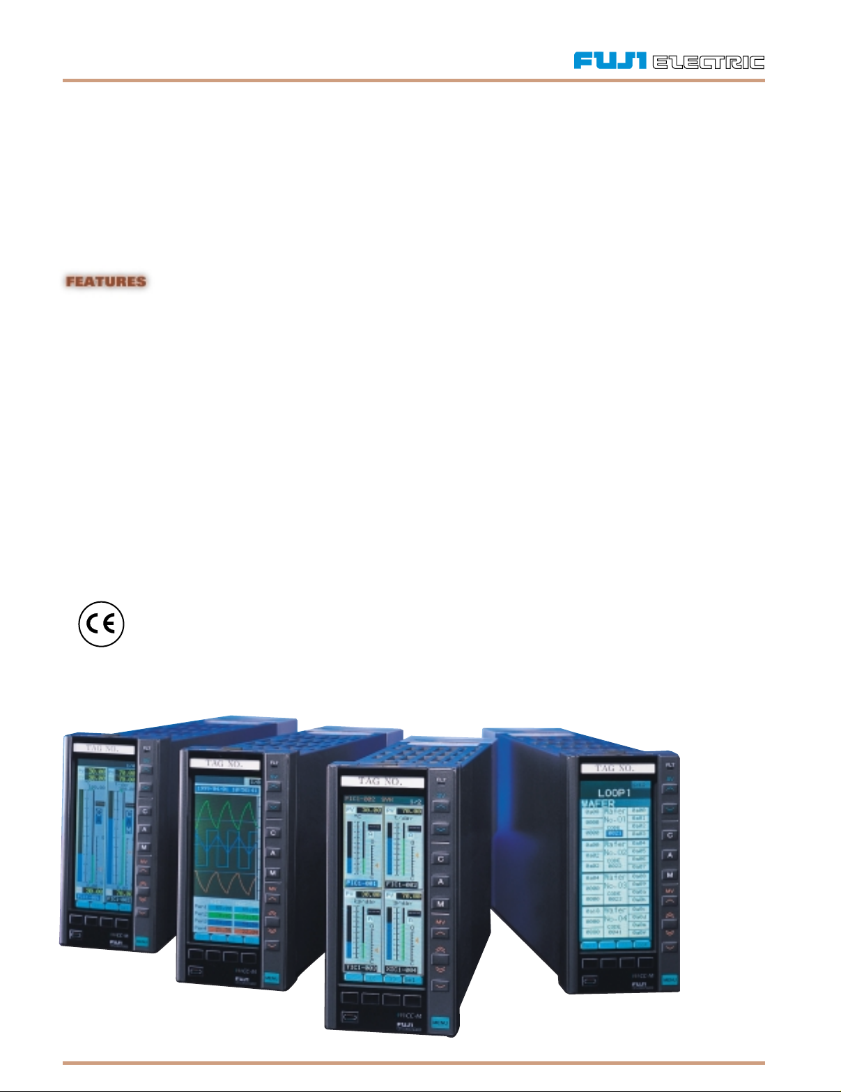
CC-M MULTI-LOOP CONTROLLER
FOUR COMPLEX PROCESSES. ONE SIMPLE SOLUTION.
Fuji Electric brings its extensive knowledge and experience in process control instrumentation into the new, state-of-the-art multi-
loop process controller, the CC-M. Intelligent integration of control and communications is the hallmark of this unique controller.
It is one of the most compact in the industry for a controller with this much sophistication and flexibility. Get up to four control
loops with a variety of control methods, advanced network features, extensive I/O expansion, data-logging with robust storage,
and user-friendly 16-color LCD display — all for a price that is unbeatable. CC-M is used in water treatment, combustion furnace,
multi-point gas analysis, chemical injection and incineration systems, to name a few.
• Multiple Loops
Up to 4 control loops, with 4 control outputs and 8 PID blocks.
• Choice of Several Control Methods
Single loop, multi-loop, cascade, ratio, PLC.
• Program Loader
Program via PC using exclusive loader software
• Advanced Network Interface
Connect multiple units with PC, PLC or to several I/O modules
• Data-Logging
Sample and store up to 1.35 million data points
• Colorful Graphical Display
16-color back-lit LCD; view trends, bar graphs, parameter menu, process status, etc.
• Back-Up Operation
Back-up unit takes over control if main unit fails
Information subject to change without notice. Prices in USD.
Page 2

CC-M, CONTINUED
CC-M SPECIFICATIONS
GENERAL
NUMBER OF LOOPS & PID 1 Loop: 1 control output/2 PID
(Selectable from the 2 Loops: 2 control outputs/4 PID
following) 4 Loops: 4 control outputs/8 PID
PROGRAMMING METHOD Control and computation functions are
implemented by combining function software
modules called Wafers. Configuration could be
performed from the keypad or from a PC.
PROGRAM CAPACITY 48 Wafers x 4 loops (max. 192 wafers); 2ksteps
of ladder. Wafer types include Primary PID,
Secondary PID, Arithmetic and Logic operators,
Square-root extraction, Ramp function, Averaging,
Sample & hold, Pulse width modulation, etc.
PROGRAMMING LOADER Wafer connections and operating parameters
SOFTWARE can be entered, edited, uploaded or downloaded
from a PC
SOFT PLC Using a PC-based configuration software such as
ISaGRAF®, PLC control can be implemented.
CC-M supports three IEC61131-3-based formats–
Ladder, Sequential Function and Function Block,
Structured Text, and Instruction List
DISPLAY 16-color graphic LCD with CFL back-light and
contrast adjustment. CC-M has three kinds of
menu screens for set-up and monitoring.
Menu 1: Select from Loop Panel screen, Bar graph
display, trend screen, Alarm status display, Analog
and digital input/output indication screen.
Menu 2: 8 different parameter setting screens
Menu 3: 5 different screens for wafer connection,
system definition, function definition and
communication setting.
BACK-UP OPERATION An optional back-up unit can be installed. In case
of a fault condition in the main unit, a balanceless
and bumpless transfer of control from the main
unit to the back-up unit can be achieved for
manual control of the process outputs.
DATA STORAGE Data from 32 different trends can be sampled
simultaneously and stored on compact flash
memory cards.
MEMORY CARD INTERFACE Capacity: 4, 20, 30 MB (30MB holds 1.35 million
data points)
Sampling Frequency: 1 second to 2 hrs.
Storage Format: ASCII
POWER SUPPLY VOLTAGE 85 to 26VAC, 47 to 63 Hz. 20 to 30 VDC (option)
RANGE
POWER CONSUMPTION 60 VA or less( 85 to 264 VAC). 30Ωor less
(20 to 30 VDC)
INPUT
NUMBER OF INPUTS 8 process inputs, or 6 process inputs and 2
temperature inputs, 10 digital inputs
PROCESS INPUTS 0 to 5 VDC, 1 to 5 VDC (default) and 0 to 10VDC.
For mA input, a 250Ω shunt resistor is required
TEMPERATURE INPUTS Thermocouple: J, K, R, B, T, E, S, N, U, WRe5-26,
PL II. RTD: Pt100
INPUT ACCURACY Process Inputs: ±0.1% of full span (FS) ±1 digit
Thermocouple: ±0.2% FS ±1 digit; B type – ±5%
for 0-400°C, S; R type – ±1% for 0-500°C
RTD: ±0.2% FS ±1 digit
INPUT SAMPLING TIME 100 ms
DIGITAL INPUTS 10 digital inputs available. No-voltage contact or
transistor input
Contact Rating: 30 VDC, 10mA
No-Voltage Contact Resistance: 200Ωor less
at ON. 100kΩ or more at OFF
Transistor Contact: 0V at ON, 24V at OFF, 8mA
Information subject to change without notice. Prices in USD.
OUTPUT
NUMBER OF OUTPUTS Up to 4 analog control outputs available,
one for each loop. 4 auxiliary analog outputs,
10 digital outputs
CONTROL OUTPUTS 4 to 20mA DC
Accuracy: ±0.2% FS
Load Resistance: 600Ω or less
AUXILIARY ANALOG 0 to 5V, 1to 5V, or 0 to 10 VDC
OUTPUTS Accuracy: ±0.1% FS
Load Resistance: 15kΩ or more
DIGITAL OUTPUTS Transistor open collector
1 V max. at ON, 10 mA max at. OFF
Output Rating: 30 VDC, 100mA max.
(resistive load)
COMMUNICATIONS
SIMULTANEOUS NETWORK CC-M can have two kinds of network interfaces
INTERFACE simultaneously — High-level and Low-level
HIGH-LEVEL NETWORK Allows CC-M to communicate with PC, PLC or
INTERFACE other controllers
Communication Protocol: Modbus®
Mode: EIARS-485, multi-drop, half-duplex,
bit-serial, 19.2kbps.
Number of Connectable Units: Max. 31 units
LOW-LEVEL NETWORK Allows CC-M to expand the number of
INTERFACE inputs/outputs
Communication Protocol: OPTO22® MISTIC
Mode: EIARS-485, half-duplex, bit-serial,
57.6kbps.
I/O Expansion: Max. 4 analog I/O;
Max. 32 digital I/O
I/O Modules: OPTO22 SNAP I/O® series.
Total number of connectable units depend on
the number of I/O points.
STRUCTURE
DIMENSIONS 72 x 144 x 280 mm (panel cutout: 68 x 138 mm)
WEIGHT 1.9 kg
PROTECTION IP54 (front face)
FLAME RESISTANCE UL94V-0
GENERAL SAFETY Conforms to IEC1010-1 (1990),
EN 61010-1 (1993)
EMC Emission EN 50081-2 (1994),
Immunity EN 50082-2 (1995)
Page 3

CC-M, CONTINUED
CC-M ORDERING INFORMATION
P D 3A A 2 B 1 C C D E E F 0
To create a part number fill in the boxes above with the appropriate number and/or letter from the corresponding box below.
Box A: Number of Control Loops
1 = 1 Loop $ 1,450
2 = 2 Loops 1,950
4 = 4 Loops 2,700
Number of control loops is the number of 4-20mA ‘control’ outputs.
Box B: Input Signal
A = DC 1–5V/4–20mA DC* N/C
C = Thermocouple** 180
D = RTD/Pt100** 180
* For current input, a precision 250Ωshunt resistor is used,
one per loop is included. Additional resistors are available.
** Thermocouple or RTD inputs are optional. If more are desired,
external transducers should be used.
Box C: Power Supply Voltage
A = 100–240 VAC N/C
B = 24 VDC N/C
Box D: Hard Manual Back-Up Unit
Y = None N/C
A = 1 Loop 180
B = 2 Loops 295
C = 4 Loops 355
Box E: Communications/Memory Card
Interface
Code = MODBUS RS-485 / OPTO22 / Memory Card Interface
Y = Without / Without / Without N/C
M = Without / Without / With $ 85
C = RS485 / Without / Without 74
U = RS485 / Without / With 158
D = RS485 / RS485 / Without 279
R = RS485 / RS485 / With 355
• Communication cable and impedance terminators are optional items.
• RS-485 communications uses Modbus protocol. OPTO 22 option
does not include modules. These are sold separately. To use OPTO 22
equipment, a brain module, module rack, and at least one module
must be purchased.
• Memory Card option only records trend data using standard
compact-flash type memory cards. Cards up to 32MB can be used
and are available as COMPACT FLASH_MB.
Box F: Programming Method
1 = Wafer N/C
2 = Soft PLC Function (ISaGRAF)* 60
* ISaGraf conforms to IEC1131. ISaGRAF programming tool is
optional item. Soft PLC and Wafer programming cannot function
simultaneously. To change programming method between ‘Wafer’
and ‘Soft PLC’, hardware modification is required.
CC-M ACCESSORIES
COMPACT FLASH CARD 16MB $ 85
COMPACT FLASH CARD 32MB 160
COMPACT FLASH CARD READER: PARALLEL PORT 90
CC-M LOADER SOFTWARE* N/C
CC-M LOADER CABLE (SERIAL PORT CONNECTION)* 35
SNAP-B3000-ENET OPTO 22 BRAIN** 695
SNAP-B8M OPTO 22 8-Module Rack 94
SNAP-B16M OPTO 22 16-Module Rack 161
SNAP-AOA-3 OPTO 22 Single-Channel 4–20mA AO 150
SNAP-AIV OPTO 22 2-Channel -10 to +10 VDC AI 182
SNAP-ODC5SRC OPTO 22 4-Channel DC Out. 5–60 VDC, 5 VDC logic source 42
SNAP-ODC5SNK OPTO 22 4-Channel DC Out. 5–60 VDC, 5 VDC logic source 42
SNAP-IDC5 OPTO 22 4-Channel Input. 10–32 VDC, 5 VDC logic 42
* CC-M Loader Cable to be used with software for uploading and downloading programs from the PC to the CC-M.
** To use the OPTO 22 functions, customers must purchase at the minimum, a brain, a rack, and an input or output module.
Information subject to change without notice. Prices in USD.
 Loading...