


 Loading...
Instruction Manual
High-performance, Vector Control Inverter (Stack Type 690V)
Thank you for purchasing our high-performance, vector control FRENIC-VG series of inverters.
•This product is designed to drive a three-phase motor. Read through this instruction manual to become familiar with proper handling and correct use.
•Improper handling might result in incorrect operation, a short life, or even a failure of this product as well as the motor.
•Deliver this manual to the end user of this product. Keep this manual in a safe place until this product is discarded.
•For instructions on how to use options, refer to the instruction manuals for those optional devices.
•For the installation and selection of peripheral equipment exclusive to the stack type of inverters, refer to the FRENIC-VG User's Manual (Stack Type Edition).
•For the configuration of the inverter functions and operating procedure, refer to the FRENIC-VG User's Manual (Unit Type / Function Codes Edition).
•For details about PWM converters and diode rectifiers, refer to the FRENIC-VG User's Manual (Stack Type Edition).
|
|
Fuji Electric Co., Ltd. |
INR-SI47-1841c-E |
Copyright © 2014-2018 Fuji Electric Co., Ltd. All rights reserved.
No part of this publication may be reproduced or copied without prior written permission from Fuji Electric Co., Ltd.
All products and company names mentioned in this manual are trademarks or registered trademarks of their respective holders.
The information contained herein is subject to change without prior notice for improvement.
Preface
Thank you for purchasing our high-performance, vector control FRENIC-VG series of inverters. This product is designed to drive a three-phase motor.
Read through this instruction manual to become familiar with proper handling for correct use. Improper handling might result in incorrect operation, a short life, or even a failure of this product as well as the motor.
The related documents are subject to change without notice. Be sure to obtain the latest editions for use.
|
|
Table of Contents |
|
Preface |
|
i |
|
Inquiries about Product and Guarantee............................................................................................................................ |
iii |
||
Safety precautions .................................................................................................................................................................. |
v |
||
Chapter 1 |
BEFORE USE ......................................................................................................................................................... |
1 |
|
1.1 |
Acceptance Inspection (Nameplates and type of inverter)............................................................................................ |
1 |
|
1.2 |
External Appearance..................................................................................................................................................... |
3 |
|
1.3 |
Precautions for Using Inverters .................................................................................................................................... |
5 |
|
1.3.1 |
Installation environment ....................................................................................................................................... |
5 |
|
1.3.2 |
Storage environment ............................................................................................................................................. |
7 |
|
1.3.3 Precautions for connection of peripheral equipment ............................................................................................. |
8 |
||
1.3.4 |
Noise reduction ..................................................................................................................................................... |
9 |
|
1.3.5 |
Leakage current..................................................................................................................................................... |
9 |
|
1.3.6 Precautions in driving a permanent magnet synchronous motor (PMSM)............................................................ |
9 |
||
Chapter 2 MOUNTING AND WIRING THE INVERTER ................................................................................................... |
10 |
||
2.1 |
Mounting the Inverter ................................................................................................................................................. |
10 |
|
2.1.1 Terminal Arrangement and Screw Sizes (Main circuit terminals)....................................................................... |
11 |
||
2.2 |
Wiring......................................................................................................................................................................... |
14 |
|
2.2.1 |
Connection diagram ............................................................................................................................................ |
14 |
|
2.2.2 Removing and mounting the front cover and the wiring guide ........................................................................... |
16 |
||
2.2.3 Precautions for long wiring (between the inverter and motor) ............................................................................ |
17 |
||
2.2.4 |
Main circuit terminals ......................................................................................................................................... |
18 |
|
2.2.5 Control circuit terminals (common to all inverter types) .................................................................................... |
20 |
||
2.2.6 Setting up the slide switches ............................................................................................................................... |
30 |
||
2.2.7 Fan power switching connector CN UX ............................................................................................................. |
32 |
||
2.3 |
Mounting and Connecting the Keypad ....................................................................................................................... |
33 |
|
2.3.1 Parts required for connection .............................................................................................................................. |
33 |
||
2.3.2 |
Mounting procedure............................................................................................................................................ |
34 |
|
2.4 |
Connecting a USB Cable ............................................................................................................................................ |
36 |
|
Chapter 3 OPERATION USING THE KEYPAD................................................................................................................... |
37 |
||
3.1 |
Names and Functions of Keypad Components ........................................................................................................... |
37 |
|
3.2 |
Programming Mode.................................................................................................................................................... |
40 |
|
3.2.1 Setting the calendar clock -- Menu #12 "DATE/TIME" ..................................................................................... |
42 |
||
Chapter 4 TEST RUN PROCEDURE.................................................................................................................................... |
46 |
||
4.1 |
Checking Prior to Powering On.................................................................................................................................. |
47 |
|
4.2 |
Powering ON and Checking ....................................................................................................................................... |
48 |
|
4.2.1 Checking the input state of PG (pulse generator) signals.................................................................................... |
48 |
||
4.2.2 Mounting direction of a PG (pulse generator) and PG signals ............................................................................ |
49 |
||
4.3 |
Selecting a Desired Motor Drive Control ................................................................................................................... |
50 |
|
4.3.1 Vector control for IM with speed sensor ............................................................................................................. |
50 |
||
4.3.2 Vector control for IM without speed sensor ........................................................................................................ |
52 |
||
4.3.3 Vector control for PMSM with speed sensor and magnetic pole position sensor ................................................ |
54 |
||
4.3.4 V/f control for IM ............................................................................................................................................... |
55 |
||
4.4 |
Running the Inverter for Operation Check ................................................................................................................. |
56 |
|
4.4.1 Test Run Procedure for Induction Motor (IM) .................................................................................................... |
56 |
||
4.4.2 Test Run Procedure for Permanent Magnet Synchronous Motor (PMSM) ......................................................... |
57 |
||
4.5 |
Selecting a Speed Command Source .......................................................................................................................... |
63 |
|
i

|
4.5.1 Setting up a speed command from the keypad .................................................................................................... |
63 |
||
|
4.5.2 Setting up a speed command with an external potentiometer ............................................................................. |
63 |
||
4.6 |
Selecting a Run Command Source ............................................................................................................................. |
|
64 |
|
|
4.6.1 Setting up a run command from the keypad........................................................................................................ |
64 |
||
|
4.6.2 Setting up a run command with digital input signals (terminals [FWD] and [REV]) ......................................... |
64 |
||
Chapter 5 |
FUNCTION CODES ............................................................................................................................................. |
|
65 |
|
5.1 |
Function Code Groups and Function Codes ............................................................................................................... |
|
65 |
|
5.2 |
About the Contents of Column Headers in Function Code Tables.............................................................................. |
66 |
||
5.3 |
Function Code Tables ................................................................................................................................................. |
|
67 |
|
|
5.3.1 F codes (Fundamental Functions) ....................................................................................................................... |
|
67 |
|
|
5.3.2 E codes (Extension Terminal Functions)............................................................................................................. |
|
71 |
|
|
5.3.3 C codes (Control Functions) ............................................................................................................................... |
|
78 |
|
|
5.3.4 P codes (Motor Parameter Functions M1)........................................................................................................... |
80 |
||
|
5.3.5 H codes (High Performance Functions) .............................................................................................................. |
|
82 |
|
|
5.3.6 A codes (Alternative Motor Parameter Functions M2/M3)................................................................................. |
89 |
||
|
5.3.7 o codes (Option Functions) ................................................................................................................................. |
|
89 |
|
|
5.3.8 |
L codes (Lift Functions)...................................................................................................................................... |
|
89 |
|
5.3.9 SF codes (Safety Functions) ............................................................................................................................... |
|
89 |
|
Chapter 6 |
TROUBLESHOOTING ........................................................................................................................................ |
|
90 |
|
6.1 |
Protective Functions ................................................................................................................................................... |
|
90 |
|
6.2 |
Before Proceeding with Troubleshooting ................................................................................................................... |
|
91 |
|
6.3 |
If an alarm code appears on the LED monitor ............................................................................................................ |
|
92 |
|
|
6.3.1 List of alarm codes.............................................................................................................................................. |
|
92 |
|
|
6.3.2 Possible causes of alarms, checks and measures................................................................................................. |
97 |
||
6.4 |
If the "Light Alarm" Indication (l-al) Appears on the LED Monitor ................................................................... |
101 |
||
6.5 |
If Neither an Alarm Code Nor "Light Alarm" Indication (l-al) Appears on the LED Monitor ............................ |
101 |
||
|
6.5.1 |
Abnormal motor operation................................................................................................................................ |
|
101 |
|
6.5.2 Problems with inverter settings......................................................................................................................... |
|
109 |
|
Chapter 7 MAINTENANCE AND INSPECTION ............................................................................................................... |
|
110 |
||
7.1 |
Inspection Interval ..................................................................................................................................................... |
|
111 |
|
7.2 |
Daily Inspection......................................................................................................................................................... |
|
111 |
|
7.3 |
Periodic Inspection .................................................................................................................................................... |
|
112 |
|
7.4 |
List of Periodic Replacement Parts............................................................................................................................ |
|
114 |
|
|
7.4.1 Judgment on service life ................................................................................................................................... |
|
114 |
|
|
7.4.2 |
Battery .............................................................................................................................................................. |
|
115 |
7.5 |
Measurement of Electrical Amounts in Main Circuit ................................................................................................ |
118 |
||
7.6 |
Insulation Test............................................................................................................................................................ |
|
119 |
|
Chapter 8 |
SPECIFICATIONS .............................................................................................................................................. |
|
120 |
|
Chapter 9 |
CONFORMITY WITH STANDARDS ............................................................................................................... |
|
122 |
|
9.1 |
Compliance with European Standards ( |
)........................................................................................................ |
122 |
|
|
9.1.1 Compatibility with Revised EMC Directive and Low Voltage Directive.......................................................... |
122 |
||
|
9.1.2 Compliance with EMC standards...................................................................................................................... |
|
123 |
|
|
9.1.3 Harmonic component regulation in the EU....................................................................................................... |
125 |
||
|
9.1.4 Compliance with the low voltage directive in the EU....................................................................................... |
126 |
||
9.2 |
Compliance with Functional Safety Standard........................................................................................................... |
|
130 |
|
|
9.2.1 |
General.............................................................................................................................................................. |
|
130 |
|
9.2.2 Notes for compliance to Functional Safety Standard ........................................................................................ |
131 |
||
|
9.2.3 |
Functional safety performance .......................................................................................................................... |
|
132 |
|
9.2.4 Inverter output state when Safe Torque Off (STO) is activated ........................................................................ |
133 |
||
|
9.2.5 ecf alarm (caused by logic discrepancy) and inverter output state................................................................. |
134 |
||
|
9.2.6 |
Prevention of restarting..................................................................................................................................... |
|
135 |
ii
Inquiries about Product and Guarantee
When making an inquiry
Upon breakage of the product, uncertainties, failure or inquiries, inform your Fuji Electric representative of the following information.
1)Inverter type (Refer to Chapter 1, Section 1.1.)
2)SER No. (serial number of equipment) (Refer to Chapter 1, Section 1.1.)
3)Function codes and their data that you changed (refer to the FRENIC-VG User's Manual, Chapter 3, Section 3.4.4.3.)
4)ROM version (refer to the FRENIC-VG User's Manual, Chapter 3, Section 3.4.4.6.)
5)Date of purchase
6)Inquiries (for example, point and extent of breakage, uncertainties, failure phenomena, and other circumstances)
Product warranty
To all our customers who purchase Fuji Electric products included in this documentation:
Please take the following items into consideration when placing your order.
When requesting an estimate and placing your orders for the products included in these materials, please be aware that any items such as specifications which are not specifically mentioned in the contract, catalog, specifications or other materials will be as mentioned below.
In addition, the products included in these materials are limited in the use they are put to and the place where they can be used, etc., and may require periodic inspection. Please confirm these points with your sales representative or directly with this company.
Furthermore, regarding purchased products and delivered products, we request that you take adequate consideration of the necessity of rapid receiving inspections and of product management and maintenance even before receiving your products.
[ 1 ] Free of charge warranty period and warranty range
(1)Free of charge warranty period
1)The product warranty period is ''1 year from the date of purchase'' or 18 months from the manufacturing week imprinted on the name place, whichever date is earlier.
2)However, in cases where the use environment, conditions of use, use frequency and times used, etc., have an effect on product life, this warranty period may not apply.
3)Furthermore, the warranty period for parts restored by Fuji Electric's Service Department is ''6 months from the date that repairs are completed.''
(2)Warranty range
1)In the event that breakdown occurs during the product's warranty period which is the responsibility of Fuji Electric, Fuji Electric will replace or repair the part of the product that has broken down free of charge at the place where the product was purchased or where it was delivered. However, if the following cases are applicable, the terms of this warranty may not apply.
The breakdown was caused by inappropriate conditions, environment, handling or use methods, etc. which are not specified in the catalog, operation manual, specifications or other relevant documents.
The breakdown was caused by the product other than the purchased or delivered Fuji's product.
The breakdown was caused by the product other than Fuji's product, such as the customer's equipment or software design, etc.
Concerning the Fuji's programmable products, the breakdown was caused by a program other than a program supplied by this company, or the results from using such a program.
The breakdown was caused by modifications, repairs or disassembly made by a party other than Fuji Electric.
The breakdown was caused by improper maintenance or replacement using consumables, etc. specified in the operation manual or catalog, etc.
The breakdown was caused by a science or technical problem that was not foreseen when making practical application of the product at the time it was purchased or delivered.
The product was not used in the manner the product was originally intended to be used.
The breakdown was caused by a reason which is not this company's responsibility, such as lightning or other disaster.
2)Furthermore, the warranty specified herein shall be limited to the purchased or delivered product alone.
3)The upper limit for the warranty range shall be as specified in item (1) above and any damages (damage to or loss of machinery or equipment, or lost profits from the same, etc.) consequent to or resulting from breakdown of the purchased or delivered product shall be excluded from coverage by this warranty.
iii
(3)Trouble diagnosis
As a rule, the customer is requested to carry out a preliminary trouble diagnosis. However, at the customer's request, this company or its service network can perform the trouble diagnosis on a chargeable basis. In this case, the customer is asked to assume the burden for charges levied in accordance with this company's fee schedule.
[ 2 ] Exclusion of liability for loss of opportunity, etc.
Regardless of whether a breakdown occurs during or after the free of charge warranty period, this company shall not be liable for any loss of opportunity, loss of profits, or damages arising from special circumstances, secondary damages, accident compensation to another company, or damages to products other than this company's products, whether foreseen or not by this company, which this company is not be responsible for causing.
[ 3 ] Repair period after production stop, spare parts supply period (holding period)
Concerning models (products) which have gone out of production, this company will perform repairs for a period of 7 years after production stop, counting from the month and year when the production stop occurs. In addition, we will continue to supply the spare parts required for repairs for a period of 7 years, counting from the month and year when the production stop occurs. However, if it is estimated that the life cycle of certain electronic and other parts is short and it will be difficult to procure or produce those parts, there may be cases where it is difficult to provide repairs or supply spare parts even within this 7-year period. For details, please confirm at our company's business office or our service office.
[ 4 ] Transfer rights
In the case of standard products which do not include settings or adjustments in an application program, the products shall be transported to and transferred to the customer and this company shall not be responsible for local adjustments or trial operation.
[ 5 ] Service contents
The cost of purchased and delivered products does not include the cost of dispatching engineers or service costs. Depending on the request, these can be discussed separately.
[ 6 ] Applicable scope of service
Above contents shall be assumed to apply to transactions and use of the country where you purchased the products. Consult the local supplier or Fuji for the detail separately.
iv

Safety precautions
Read this manual thoroughly before proceeding with installation, connections (wiring), operation, or maintenance and inspection. Ensure you have sound knowledge of the device and familiarize yourself with all safety information and precautions before proceeding to operate the inverter.
Safety precautions are classified into the following two categories in this manual.
Failure to heed the information indicated by this symbol may lead to dangerous conditions, possibly resulting in death or serious bodily injuries.
Failure to heed the information indicated by this symbol may lead to dangerous conditions, possibly resulting in minor or light bodily injuries and/or substantial property damage.
Failure to heed the information contained under the CAUTION title can also result in serious consequences. These safety precautions are of utmost importance and must be observed at all times.
Application
•The FRENIC-VG is designed to drive a three-phase motor. Do not use it for single-phase motors or for other purposes.
Fire or an accident could occur.
•Use this product in combination with a Fuji authorized PWM converter or diode rectifier. The product connected with a commercial power cannot drive a three-phase motor by itself.
Fire or an accident could occur.
•The FRENIC-VG may not be used for a life-support system or other purposes directly related to the human safety.
•Though the FRENIC-VG is manufactured under strict quality control, install safety devices for applications where serious accidents or property damages are foreseen in relation to the failure of it.
An accident could occur.
Installation
•Install the inverter on a base made of metal or other non-flammable material.
Otherwise, a fire could occur.
•Do not place flammable object nearby.
Doing so could cause fire.
•The inverter whose protective structure is IP00 involves a possibility that a human body may touch the live conductors of the main circuit terminal block. Install the inverter in an inaccessible place.
Otherwise, electric shock or injuries could occur.
•Do not support the inverter by its front cover during transportation.
Doing so could cause a drop of the inverter and injuries.
•Prevent lint, paper fibers, sawdust, dust, metallic chips, or other foreign materials from getting into the inverter or from accumulating on the heat sink.
•When installing the inverter, use screws and bolts specified in the installation procedure and tighten them with the specified tightening torque.
Otherwise, a fire or an accident might result.
•Do not install or run an inverter that is damaged or lacking parts.
Doing so could cause fire, an accident or injuries.
v

Wiring
•If no zero-phase current (earth leakage current) detective device such as a ground-fault relay is installed in the upstream power supply line in order to avoid the entire power supply system's shutdown undesirable to factory operation, install a residual-current-operated protective device (RCD)/earth leakage circuit breaker (ELCB) individually to the input line of the PWM converter or diode rectifier.
•When wiring a PWM converter or diode rectifier to the power source, insert a recommended molded case circuit breaker (MCCB) or residual-current-operated protective device (RCD)/earth leakage circuit breaker (ELCB) (with overcurrent protection) in the path of each pair of power lines to those devices. Use the recommended devices within the recommended current capacity.
•Use wires in the specified size.
•Tighten terminals with specified torque.
Otherwise, a fire could occur.
•When there is more than one combination of an inverter and motor, do not use a multicore cable for the purpose of handling their wirings together.
•Do not connect a surge killer to the inverter's output (secondary) circuit.
Doing so could cause a fire.
•According to the input voltage series of the PWM converter or diode rectifier, ground the inverter in compliance with the national or local electric code.
•Be sure to ground the grounding terminals ( G) of the inverter and the PWM converter/diode rectifier.
Otherwise, an electric shock or a fire could occur.
•Qualified electricians should carry out wiring.
•Be sure to perform wiring after turning the power OFF.
Otherwise, an electric shock could occur.
•Be sure to perform wiring after installing the inverter unit.
Otherwise, an electric shock could occur.
•Ensure that the number of input phases and the rated voltage of the PWM converter or diode rectifier match the number of phases and the voltage of the AC power supply to which the PWM converter or diode rectifier is to be connected.
Otherwise, a fire or an accident could occur.
•Do not connect the PWM converter or diode rectifier to the inverter's output terminals (U, V, and W).
Doing so could cause fire or an accident.
•In general, sheaths of the control signal wires are not specifically designed to withstand a high voltage (i.e., reinforced insulation is not applied). Therefore, if a control signal wire comes into direct contact with a live conductor of the main circuit, the insulation of the sheath might break down, which would expose the signal wire to a high voltage of the main circuit. Make sure that the control signal wires will not come into contact with live conductors of the main circuit.
Doing so could cause an accident or an electric shock.
•Before changing the slide switches on the control printed circuit board, turn the power OFF, wait at least ten minutes, and make sure that the LED monitor and charging lamp are turned OFF. Further, make sure, using a multimeter or a similar instrument, that the DC link bus voltage between the terminals P(+) and N(-) has dropped to the safe level (+25 VDC or below). Note that the diode rectifier has no LED monitor function.
An electric shock could occur.
•The PWM converter, inverter, motor and wiring generate electric noise. Be careful about malfunction of the nearby sensors and devices. To prevent them from malfunctioning, implement noise control measures.
Otherwise an accident could occur.
vi

Operation
•Be sure to mount the front cover before turning the power ON. Do not remove the cover when the inverter power is ON.
Otherwise, an electric shock could occur.
•Do not operate switches with wet hands.
Doing so could cause electric shock.
•If the auto-reset function has been selected, the inverter may automatically restart and drive the motor depending on the cause of tripping. Design the machinery or equipment so that human safety is ensured at the time of restarting.
Otherwise, an accident could occur.
•If the stall prevention function (torque limiter) has been selected, the inverter may operate with acceleration/deceleration or speed different from the commanded ones. Design the machine so that safety is ensured even in such cases.
•The  key on the keypad is effective only when the keypad operation is enabled with function code F02 (= 0, 2 or 3). When the keypad operation is disabled, prepare an emergency stop switch separately for safe operations. Switching the run command source from keypad (local) to external equipment (remote) by turning ON the "Enable communications link" command LE disables the
  key.
key.
•If any of the protective functions have been activated, first remove the cause. Then, after checking that the all run commands are set to OFF, release the alarm. If the alarm is released while any run commands are set to ON, the inverter may supply the power to the motor, running the motor.
Otherwise, an accident could occur.
•If you enable the "Restart mode after momentary power failure" (Function code F14 = 3 to 5), then the inverter automatically restarts running the motor when the power is recovered.
Design the machinery or equipment so that human safety is ensured after restarting.
•If the user configures the function codes wrongly without completely understanding this Instruction Manual and the FRENIC-VG User's Manual, the motor may rotate with a torque or at a speed not permitted for the machine.
•Starting auto-tuning rotates the motor. Confirm sufficiently that there is no risk in rotating the motor beforehand.
An accident or injuries could occur.
•Even if the inverter has interrupted power to the motor, if the voltage is applied to the main input power of the PWM converter or diode rectifier, voltage may be output to inverter's output terminals U, V, and W.
•Even if the motor is stopped due to DC braking or preliminary excitation, voltage is output to inverter output terminals U, V, and W.
An electric shock may occur.
•The inverter can easily accept high-speed operation. When changing the speed setting, carefully check the specifications of motors or equipment beforehand.
Otherwise, injuries could occur.
•Do not touch the heat sink because it becomes very hot.
Doing so could cause burns.
•The DC brake function of the inverter does not provide any holding mechanism.
Injuries could occur.
•Ensure safety before modifying function code settings.
Run commands (e.g., "Run forward" FWD), stop commands (e.g., "Coast to a stop" BX), and speed change commands can be assigned to digital input terminals. Depending upon the input terminal operation, modifying the function code setting may cause a sudden motor start or an abrupt change in speed.
•When the inverter is controlled with the digital input signals, switching run or speed command sources with the related terminal commands (e.g., SS1, SS2, SS4, SS8, N2/N1, KP/PID, IVS, and LE) may cause a sudden motor start or an abrupt change in speed.
An accident or injuries could occur.
vii

Maintenance and inspection, and parts replacement
•Before changing the slide switches on the control printed circuit board in maintenance or inspection, turn the power OFF, wait at least ten minutes, and make sure that the LED monitor and charging lamp are turned OFF. Further, make sure, using a multimeter or a similar instrument, that the DC link bus voltage between the terminals P(+) and N(-) has dropped to the safe level (+25 VDC or below). Note that the diode rectifier has no LED monitor function.
Otherwise, an electric shock could occur.
•Always carry out the daily and periodic inspections described in the instruction/user's manual. Use of the inverter for long periods of time without carrying out regular inspections could result in malfunction or damage, and an accident or fire could occur.
•It is recommended that periodic inspections be carried out every one to two years, however, they should be carried out more frequently depending on the usage conditions.
•It is recommended that parts for periodic replacement be replaced in accordance with the standard replacement frequency indicated in the user's manual. Use of the product for long periods of time without replacement could result in malfunction or damage, and an accident or fire could occur.
•Contact outputs [30A/B/C] and [Y5A/C] use relays, and may remain ON, OFF, or undetermined when their lifetime is reached. In the interests of safety, equip the inverter with an external protective function.
•If it continues using it in spite of having exhausted the battery, data may disappear.
Otherwise, an accident or fire could occur.
•Maintenance, inspection, and parts replacement should be made only by qualified persons.
•Take off the watch, rings and other metallic objects before starting work.
•Use insulated tools.
Otherwise, an electric shock or injuries could occur.
•Never modify the inverter.
Doing so could cause an electric shock or injuries.
Disposal
•Treat the FRENIC-VG as an industrial waste when disposing of it.
Otherwise injuries could occur.
•The battery used in the inverter is a so-called primary battery. When disposing of it, comply with local codes and regulations.
Speed control mode
•If the control parameters of the automatic speed regulator (ASR) are not appropriately configured under speed control, even turning the run command OFF may not decelerate the motor due to hunting caused by high gain setting. Accordingly, the inverter may not reach the stop conditions so that it may continue running.
During deceleration, hunting may be caused by high response in low speed domain so that the detected speed deviates from the zero speed area before the zero speed control duration (F39) elapses. Accordingly, the inverter will not reach the stop conditions so that it enters the deceleration mode again and continues running.
If any of the above problems occurs, adjust the ASR control parameters to appropriate values and use the speed mismatch alarm function in order to alarm-trip the inverter, switch the control parameters by speed, or judge the detection of a stop speed by commanded values when the actual speed deviates from the commanded one.
An accident or injuries could occur.
Torque control mode
•When the motor is rotated by load-side torque exceeding the torque command under torque control, turning the run command OFF may not bring the stop conditions so that the inverter may continue running.
An accident or injuries could occur.
•To shut down the inverter output, switch from torque control to speed control and apply a decelerate-to-stop or coast-to-stop command.
General precautions
viii
Drawings in this manual are illustrated without the front cover or safety shields for explanation of detail parts. Do not turn the power ON when the inverter is as shown in drawings. Be sure to restore the covers and shields in the original state before running the inverter.
Icons
The following icons are used throughout this manual.
This icon indicates information which, if not heeded, can result in the inverter not operating to full efficiency, as well as information concerning incorrect operations and settings which can result in accidents.
This icon indicates information that can prove handy when performing certain settings or operations.
This icon indicates a reference to more detailed information.
ix

Chapter 1 BEFORE USE
1.1 Acceptance Inspection (Nameplates and type of inverter)
Unpack the package and check the following:
(1)An inverter and the following accessories are contained. Accessories - Instruction manual (this document)
-CD-ROM (containing the FRENIC-VG User's Manual, FRENIC-VG Loader (free version), and FRENIC-VG Loader Instruction Manual)
(2)The inverter has not been damaged during transportation—there should be no dents or parts missing.
(3)The inverter is the type you ordered. You can check the type and specifications on the main and sub nameplates. (The main and sub nameplates are attached to the inverter as shown in Figures 1.2-1 through 1.2-4.)
(a) Main Nameplate |
|
|
|
(b) Sub Nameplate |
||||||
Figure 1.1-1 Nameplates (Example) |
||||||||||
TYPE: Type of inverter |
|
|
|
|
||||||
FRN 90 S VG 1 S |
|
69□ |
||||||||
|
||||||||||
|
|
|
|
|
|
|
|
|
|
|
|
|
|
|
|
Code |
Series name |
|
|
|
FRN |
FRENIC series |
|
|
|
|
|
|
|
|
Code |
Nominal applied motor |
|
|
|
90 |
90kW |
|
|
|
110 |
110kW |
|
|
|
132 |
132kW |
|
|
|
|
|
|
||
|
|
|
|
|
450 |
450kW |
|
|
|
|
|
|
|
|
Code |
Structure |
|
|
|
|
|
|
||
S |
Standard stack type |
|
|
|
|
|
|
|
|
Code |
Shipping destination |
|
|
|
|
|
Instructon manual language |
|
|
|
|
|
|
|
|
|
|
|
|
|
J |
Japan/Japanease |
|
|
|
|
|
||
|
|
|
|
|
E |
EU/English |
|
|
|
|
|
C |
China/Chinese |
|
|
|
|
|
|
|
|
|
|
|
|
Code |
Power supply voltage |
|
|
|
|
|
69 |
Three-phase 690V |
|
|
|
|
|
|
|
|
|
|
|
|
Code |
Enclosure |
|
|
|
|
|
S |
Basic type |
|
|
|
|
|
|
|
|
|
|
|
|
Code |
Development code |
|
|
|
|
|
1 |
1 series |
|
|
|
|
|
|
|
|
|
|
|
|
Code |
Appicable area |
|
|
|
|
|
VG |
High performance, |
|
|
|
|
|
vector control |
|
|
|
|
|
|
|
1

The FRENIC-VG is available in two drive modes depending upon the inverter capacity: Medium Duty (MD) and Low Duty (LD) modes. Specifications in each mode are printed on the main nameplate.
Medium Duty : MD mode designed for medium duty load applications.
Overload capability: 150% for 1 min. Continuous ratings = Inverter capacity
Low Duty |
: LD mode designed for light duty load applications. |
|
Overload capability: 110% for 1 min. Continuous ratings = One rank higher capacity of inverters |
SOURCE |
: Input current |
OUTPUT |
: Number of output phases, rated output voltage, output frequency range, rated output capacity, rated output |
|
current, and overload capability |
MASS |
: Mass of the inverter in kilogram |
SER. No. |
: Product number |
4 2 A 1 2 3 A 0 0 0 1 AA 4 0 5
Production week
This indicates the week number that is numbered from the 1st week of January.
The 1st week of January is indicated as "01." Production year: Last digit of year
Product version
: Compliance with European Standards (See Chapter 9 Section 9.1)
If you suspect the product is not working properly or if you have any questions about your product, contact your Fuji Electric representative.
2

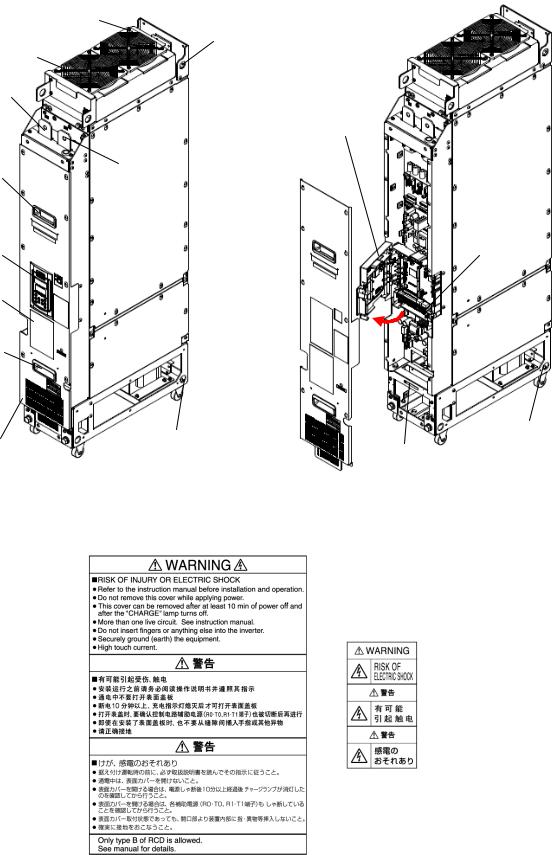
1.2 External Appearance
(1) Outside and inside views
Cooling fans |
Hoist hole |
|
φ18 |
||
Hoist hole |
||
|
||
φ18 |
|
|
|
P(+) bar |
|
|
N(-) bar |
|
|
Keypad |
|
Keypad |
enclosure |
|
|
Hoist holes |
|
|
φ18 |
|
|
|
|
|
Controle circuit |
Warning |
|
|
|
|
terminal block |
|
|
|
|
|
|
plate |
|
|
|
|
|
|
|
|
|
|
|
Front cover |
|
|
|
|
Sub nameplate |
|
|
Handle |
|||
|
|
|
|||
|
|
|
|
||
Main nameplate |
|
|
|
|
|
|
|
Figure 1.2-1 Rank 2 (90 to 110 kW) |
|
||
Hoist hole |
|
|
|
|
|
φ26 |
|
|
Hoist hole |
|
|
Cooling fans |
|
|
φ26 |
|
|
|
|
|
|
|
|
Hoist hole |
|
|
|
|
|
φ26 |
|
|
|
|
|
|
|
|
P(+) bar |
|
|
|
|
|
N(-) bar |
|
|
Handle |
|
|
|
|
|
|
Hoist hole |
Keypad |
|
||
|
enclosure |
|
|||
|
φ26 |
|
|
||
|
|
|
|
|
|
|
|
|
|
|
Controle circuit |
Keypad |
|
|
|
|
terminal block |
Warning plate
|
|
Main |
Handle |
|
nameplate |
|
|
Casters
Front cover |
|
Hoist holes |
|
|
φ26 |
Sub nameplate |
|
|
|
||
|
|
|
|
|
|
Figure 1.2-2 Rank 3 (132 to 200 kW) |
|
3
Hoist hole |
|
φ26 |
Hoist hole |
Cooling fans |
φ26 |
|
|
N(-) bar |
|
|
Keypad |
|
enclosure |
Handle |
P(+) bar |
|
Controle circuit |
Keypad |
terminal block |
Warning |
|
plate |
|
Handle |
|
|
|
Hoist holes |
Casters |
Front cover |
|
|
|
|
|
||
|
φ26 |
Sub nameplate |
|
|
|
Figure 1.2-3 Rank 4 (250 to 450 kW) |
|
(2) Warning plates and label
Figure 1.2-4 Warning Plates and Label
4
1.3 Precautions for Using Inverters
This section provides precautions in introducing inverters, e.g. precautions for installation environment, power supply lines, wiring, and connection to peripheral equipment. Be sure to observe those precautions.
1.3.1Installation environment
Install the inverter in an environment that satisfies the requirements listed in Table 1.3-1.
|
Table 1.3-1 Environmental Requirements |
|
|
|
|
|
|
Item |
Specifications |
|
|
|
|
|
|
Site location |
Indoors |
|
|
|
|
|
|
Ambient temperature |
-10 to +40 C |
|
|
|
|
|
|
Relative humidity |
5 to 95% (No condensation) |
|
|
|
|
|
|
Atmosphere |
The inverter must not be exposed to dust, direct sunlight, corrosive gases, flammable gases, oil |
||
|
mist, vapor or water drops. |
|
|
|
Pollution degree 2 (IEC60664-1) (Note 1) |
|
|
|
The atmosphere can contain a small amount of salt. (0.01 mg/cm2 or less per year) |
||
|
The inverter must not be subjected to sudden changes in temperature that will cause |
||
|
condensation to form. |
|
|
|
|
|
|
Altitude |
Less than 1,000 m |
|
|
|
If the altitude is 1,000 to 3,000 m, output current derating is required. (Note 2) |
||
|
If the altitude is 2,001 to 3,000 m, the insulation level of the control circuits lowers from the |
||
|
reinforced insulation to the basic insulation. |
|
|
|
|
|
|
Vibration |
Compliant to the standard IEC61800-2 |
Compliant to the standard IEC61800-5-1 |
|
|
Amplitude 0.3 mm: 2 to less than 9 Hz |
Amplitude 0.075 mm: |
10 to less than 57 Hz |
|
1 m/s2: 9 to 200 Hz |
1 G: |
57 to 150 Hz |
(Note 1) Do not install the inverter in an environment where it may be exposed to lint, cotton waste or moist dust or dirt which will clog the heat sink of the inverter. If the inverter is to be used in such an environment, install it in a dustproof cabinet.
(Note 2) If you use the inverter in an altitude above 1000 m, you should apply an output current derating factor as listed in Table 1.3-2.
Table 1.3-2 Output Current Derating Factor in Relation to Altitude
Altitude |
Output current derating factor |
|
|
1000 m or lower |
1.00 |
|
|
1000 to 1500 m |
0.97 |
|
|
1500 to 2000 m |
0.95 |
|
|
2000 to 2500 m |
0.91 |
|
|
2500 to 3000 m |
0.88 |
|
|
5

Fuji Electric strongly recommends installing inverters in a cabinet for safety reasons, in particular, when installing the ones whose enclosure rating is IP00.
When installing the inverter in a place out of the specified environmental requirements, it is necessary to derate the inverter or consider the cabinet engineering design suitable for the special environment or the cabinet installation location. For details, refer to the Fuji Electric technical information "Engineering Design of Panels" or consult your Fuji Electric representative.
The special environments listed below require using the specially designed cabinet or considering the cabinet installation location.
Environments |
Possible problems |
Sample measures |
Applications |
|
|
|
|
Highly concentrated |
Corrosive gases cause parts |
Any of the following measures may |
Paper manufacturing, |
sulfidizing gas or |
inside the inverter to corrode, |
be necessary. |
sewage disposal, sludge |
other corrosive gases |
resulting in an inverter |
- Mount the inverter in a sealed |
treatment, tire |
|
malfunction. |
manufacturing, gypsum |
|
|
cabinet with IP6X or air-purge |
||
|
|
manufacturing, metal |
|
|
|
mechanism. |
|
|
|
processing, and a |
|
|
|
|
|
|
|
- Place the cabinet in a room free |
particular process in |
|
|
from influence of the gases. |
textile factories. |
|
|
|
|
A lot of conductive |
Entry of conductive dust into |
Any of the following measures may |
Wiredrawing machines, |
dust or foreign |
the inverter causes a short |
be necessary. |
metal processing, |
material (e.g., metal |
circuit. |
- Mount the inverter in a sealed |
extruding machines, |
powders or shavings, |
|
printing presses, |
|
|
cabinet. |
||
carbon fibers, or |
|
combustors, and industrial |
|
|
|
||
carbon dust) |
|
- Place the cabinet in a room free |
waste treatment. |
|
|
from influence of the conductive |
|
|
|
dust. |
|
|
|
|
|
A lot of fibrous or |
Fibrous or paper dust |
Any of the following measures may |
Textile manufacturing and |
paper dust |
accumulated on the heat sink |
be necessary. |
paper manufacturing. |
|
lowers the cooing effect. |
- Mount the inverter in a sealed |
|
|
|
|
|
|
Entry of dust into the inverter |
cabinet that shuts out dust. |
|
|
causes the electronic circuitry |
- Ensure a maintenance space for |
|
|
to malfunction. |
|
|
|
periodical cleaning of the heat sink |
|
|
|
|
|
|
|
|
in cabinet engineering design. |
|
|
|
- Employ external cooling when |
|
|
|
mounting the inverter in a cabinet |
|
|
|
for easy maintenance and perform |
|
|
|
periodical maintenance. |
|
|
|
|
|
High humidity or |
In an environment where a |
- Put a heating module such as a |
Outdoor installation. |
dew condensation |
humidifier is used or where |
space heater in the cabinet. |
Film manufacturing line, |
|
the air conditioner is not |
|
|
|
|
pumps and food |
|
|
equipped with a |
|
|
|
|
processing. |
|
|
dehumidifier, high humidity |
|
|
|
|
|
|
|
or dew condensation results, |
|
|
|
which causes a |
|
|
|
short-circuiting or |
|
|
|
malfunction of electronic |
|
|
|
circuitry inside the inverter. |
|
|
|
|
|
|
Vibration or shock |
If a large vibration or shock |
- Put shock-absorbing materials on |
Installation of an inverter |
exceeding the |
exceeding the specified level |
the mounting base of the inverter |
cabinet on a carrier or |
specified level |
is applied to the inverter, for |
for safe mounting. |
self-propelled machine. |
|
example, due to a carrier |
|
Ventilating fan at a |
|
running on seam joints of |
|
|
|
|
construction site or a press |
|
|
rails or blasting at a |
|
|
|
|
machine. |
|
|
construction site, the inverter |
|
|
|
|
|
|
|
structure gets damaged. |
|
|
|
|
|
|
Fumigation for |
Halogen compounds such as |
- When exporting an inverter built |
Exporting. |
export packaging |
methyl bromide used in |
in a cabinet or equipment, pack |
|
|
fumigation corrodes some |
them in a previously fumigated |
|
|
parts inside the inverter. |
wooden crate. |
|
|
|
- When packing an inverter alone |
|
|
|
for export, use a laminated veneer |
|
|
|
lumber (LVL). |
|
6
1.3.2Storage environment
The storage environment in which the inverter should be stored after purchase differs from the installation environment. Store the inverter in an environment that satisfies the requirements listed below.
[ 1 ] Temporary storage
Table 1.3-3 Storage and Transport Environments
Item |
|
|
Specifications |
|
|
|
|
Storage temperature *1 |
-25 to +70 C |
|
Places not subjected to abrupt temperature changes or |
|
|
|
|
Relative humidity |
5 to 95% *2 |
|
condensation or freezing |
Atmosphere |
The inverter must not be exposed to dust, direct sunlight, corrosive or flammable gases, oil mist, vapor, |
||
|
water drops or vibration. The atmosphere must contain only a low level of salt. (0.01 mg/cm2 or less |
||
|
per year) |
|
|
|
|
|
|
Atmospheric pressure |
86 to 106 kPa (during storage) |
|
|
|
|
|
|
|
70 to 106 kPa (during transportation) |
|
|
|
|
|
|
*1 Assuming comparatively short time storage, e.g., during transportation or the like.
*2 Even if the humidity is within the specified requirements, avoid such places where the inverter will be subjected to sudden changes in temperature that will cause condensation or freezing.
Precautions for temporary storage
(1)Do not leave the inverter directly on the floor.
(2)If the environment does not satisfy the specified requirements listed in Table 1.3-3, wrap the inverter in an airtight vinyl sheet or the like for storage.
(3)If the inverter is to be stored in a high-humidity environment, put a drying agent (such as silica gel) in the airtight package described in (2) above.
[ 2 ] Long-term storage
The long-term storage method of the inverter varies largely according to the environment of the storage site. General storage methods are described below.
(1)The storage site must satisfy the requirements specified for temporary storage.
However, for storage exceeding three months, the ambient temperature range should be within the range from -10 to 30°C. This is to prevent electrolytic capacitors in the inverter from deterioration.
(2)The package must be airtight to protect the inverter from moisture. Add a drying agent inside the package to maintain the relative humidity inside the package within 70%.
(3)If the inverter has been installed to the equipment or cabinet at construction sites where it may be subjected to humidity, dust or dirt, then temporarily remove the inverter and store it in the environment specified in Table 1.3-3.
Precautions for storage over 1 year
If the inverter has not been powered on for a long time, the property of the electrolytic capacitors may deteriorate. Power the inverters on once a year and keep the inverters powering on for 30 to 60 minutes. Do not connect the inverter to the load circuit (secondary side) or run the inverter.
7
1.3.3Precautions for connection of peripheral equipment
[ 1 ] Fuses
Fuses have their own service life. It is recommended that they be replaced periodically. Secure them since improper setting could cause an unexpected accident at the time of fuse melting.
[ 2 ] Circuit breakers and disconnectors
(Molded case circuit breaker (MCCB) or residual-current-operated protective device (RCD)/earth leakage circuit breaker (ELCB))
The MCCB or RCD/ELCB cannot apply to the inverter DC common input side or output circuit because of their properties.
-The inverter output circuit has the inverter protective functions (for overcurrent, grounding fault, phase loss, etc.), so it does not require using circuit breakers or disconnectors. In particular, no ELCB can be used.
When using an MCCB unavoidably for grounding fault protection, use such an MCCB that trips with the current larger than the inverter rated capacity. Confirm the protective coordination with the wire size. Also select the MCCB specifications suitable for the user specifications.
-Use a non-auto switch with the overcurrent trip function removed, as a disconnector.
[ 3 ] Magnetic contactors (MC)
For magnetic contactors to be installed at the DC common input side or output circuit, a sequence should be configured so that they open or close when the inverter is stopped (during inverter gate shutdown).
[ 4 ] Motor overload protection
The inverter has the electronic thermal overload protection function for motors. Use it when a single inverter drives a single motor.
In any of the following cases, the electronic thermal overload protection function cannot protect the motor, so use a thermistor (NTC/PTC) or thermal relay to protect the motor.
-In applications where start and stop are frequently repeated, great fluctuation of the load is frequently repeated, or the inverter drives in very low-speed domain continuously.
-Driving motors (whose electronic thermal overload characteristics are different) other than standard 3-phase motors
Do not use a thermal relay at the inverter DC common power side. This is because the inverter DC common power is DC voltage containing high frequency components.
8
1.3.4Noise reduction
If noise generated from the inverter affects other devices, or that generated from peripheral equipment causes the inverter to malfunction, follow the basic measures outlined below.
(1)If noise generated from the inverter affects the other devices through power wires or grounding wires:
-Isolate the grounding terminals of the inverter from those of the other devices.
-Connect a noise filter to the inverter power wires.
-Isolate the power system of the other devices from that of the inverter with an insulated transformer.
(2)If induction or radio noise generated from the inverter affects other devices:
-Isolate the main circuit wires from the control circuit wires and other device wires.
-Put the main circuit wires through a metal conduit pipe, and connect the pipe to the ground near the inverter.
-Install the inverter into a metal cabinet and connect the whole cabinet to the ground.
-Connect a noise filter to the inverter's power wires.
(3)When implementing measures against noise generated from peripheral equipment:
-For inverter's control signal wires, use twisted or shielded-twisted wires. When using shielded-twisted wires, connect the shield of the shielded wires to the common terminals of the control circuit.
-Connect a surge absorber in parallel with magnetic contactor's coils or other solenoids (if any).
1.3.5Leakage current
A high frequency current component generated by insulated gate bipolar transistors (IGBTs) switching on/off inside the inverter becomes leakage current through stray capacitance of inverter input and output wires or a motor. If any of the problems listed below occurs, take an appropriate measure against them.
Problem |
|
Measures |
|
|
|
||
An earth leakage circuit |
1) Make the wires between the inverter and motor shorter. |
||
breaker* that is connected |
2) |
Use an earth leakage circuit breaker with lower sensitivity than the one currently used. |
|
to the input (primary) side |
|||
3) |
Use an earth leakage circuit breaker that features measures against the high frequency |
||
has tripped. |
|||
|
current component (Fuji SG and EG series). |
||
|
|
||
*With overcurrent protection |
|
|
|
|
|
|
|
An external thermal relay |
1) |
Increase the current setting of the thermal relay. |
|
was falsely activated. |
2) |
Use the electronic thermal overload protection built in the inverter, instead of the |
|
|
|||
|
|
external thermal relay. |
|
|
|
|
|
1.3.6Precautions in driving a permanent magnet synchronous motor (PMSM)
When using a PMSM, note the following.
•When using a PMSM, consult your Fuji Electric representative.
•A single inverter cannot drive two or more PMSMs.
•A PMSM cannot be driven by commercial power.
9

Chapter 2 MOUNTING AND WIRING THE INVERTER
2.1 Mounting the Inverter
(1) Installation environment
Mount the inverter at the place satisfying the requirements given in Chapter 1, Section 1.3.1 "Installation environment."
(2) Mounting base
Install the inverter on a base made of metal or other non-flammable material. Do not mount the inverter upside down or horizontally.
Install the inverter on a base made of metal or other non-flammable material.
Otherwise, a fire could occur.
(3) Clearances
Mount the stack only in the direction shown in Figure 2.1-1 (in the reading direction of the nameplate). For the clearances, refer to Figure 2.1-1 and Table 2.1-1. When mounting two or more stacks side by side, observe also the clearances specified in Table 2.1-1.
C
E
B A
|
|
|
D |
|
|
|
|
|
|
|
Figure 2.1-1 Mounting Direction and Required Clearances |
||||
Table 2.1-1 Clearances (mm) |
|
|
|
|
|
||
|
|
A |
B |
C |
D |
E |
|
Between stacks |
Rank 2 |
10 |
10 |
300 |
350 |
50 |
Rank 2: 55 to 110 kW stack size |
Rank 3 |
|
|
|
|
20 |
Rank 3: 132 to 200 kW stack size |
|
|
|
|
|
|
|||
|
Rank 4 |
|
|
|
|
20 |
Rank 4: 250 to 450 kW stack size |
With other |
20 |
50 |
- |
350 |
50 |
|
equipment |
(100) |
|||||
|
|
|
|
-Stacks cannot be mounted, one above the other.
-Above the stack (i.e. above the exhaust fans) at location "C," only a DC fuse (authorized by Fuji) can be mounted. To mount general devices, select devices whose maximum allowable working temperature is 70 C and prevent them from interfering with the effect of the exhaust fans.
-Beneath the stack (i.e. beneath the intake vent) at location "D," do not block about 60% of the area in the 350 mm clearance. When mounting a device, ensure a 100 mm clearance.
10

2.1.1Terminal Arrangement and Screw Sizes (Main circuit terminals)
[ 1 ] |
Rank 2 (90 to 110 kW) |
|
(Unit mm) <Internal front view> |
<Right side view> |
|
Terminal name |
Symbol |
Screw size |
Tightening torque |
Applicable crimp terminal size |
|
|
|
|
|
Output terminal |
U, V, W |
M10 |
27 N m |
R150-10/MAX |
|
|
|
|
|
DC input terminal |
P(+), N(-) |
|
|
|
|
|
|
|
|
Grounding terminal |
G |
|
|
|
Figure 2.1-2 Rank 2 (90 to 110 kW)
11

[ 2 ] Rank 3 (132 to 200 kW) |
|
(Unit: mm) <Internal front view> |
<Right side view> |
For output terminals of rank 3, the cabinet should have relay bar terminals.
Secure terminals with insulators to prevent them from short-circuiting each other.
Terminal name |
Symbol |
Bolt size |
Tightening |
|
torque |
||||
|
|
|
||
Output terminal |
U, V, W |
M12 |
48 N m |
|
|
|
|
|
|
DC input terminal |
P(+), N(-) |
|
|
|
|
|
|
|
|
Grounding terminal |
G |
|
|
|
|
|
|
|
Figure 2.1-3 Rank 3 (132 to 200 kW)
12

[ 4 ] Rank 4 (250 to 450 kW) |
|
|
(Unit: mm) |
<Internal front view> |
<Right side view> |
|
|
|
For output terminals of rank 4, the cabinet should have relay bar terminals.
Secure terminals with insulators to prevent them from short-circuiting each other.
Terminal name |
Symbol |
Bolt size |
Tightening |
|
torque |
||||
|
|
|
||
|
|
|
|
|
Output terminal |
U, V, W |
M12 |
48 N m |
|
|
|
|
|
|
DC input terminal |
P(+), N(-) |
|
|
|
|
|
|
|
|
Grounding terminal |
G |
|
|
|
|
|
|
|
Figure 2.1-4 Rank 4 (250 to 450 kW)
13
2.2 Wiring
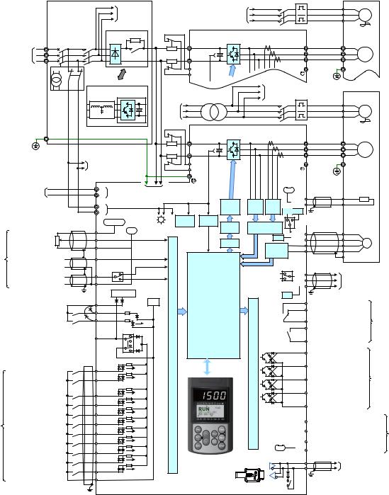
2.2.1Connection diagram
[ 1 ] Standard stack
The connection example of the standard stack type is shown below.
|
|
|
|
|
|
|
|
|
|
|
|
|
|
|
|
|
TH1 (Note 10) |
|
|
|
|
|
|
|
Power panel |
MFR |
|
|
|
|
|
|
MFR1 |
MC-F1 |
|
|
FU |
|
|
|
|||||
|
|
MFS |
Fan power |
|
|
|
|
|
|
|
|
|
|
|
||||||||
|
|
|
|
|
|
|
|
|
MFS1 |
|
|
|
|
FV |
|
|
|
|||||
|
|
|
|
|
MFT |
input |
|
|
|
|
|
|
|
|
MF1 |
|
|
|||||
|
|
|
|
|
|
|
|
|
MFT1 |
|
|
|
|
FW |
|
|
||||||
|
|
|
|
|
|
|
|
(Note 12) |
|
|
|
|
|
|
|
|
|
|
||||
|
|
|
|
|
|
|
|
|
|
|
|
|
|
|
|
|
|
|
|
|
||
|
|
|
|
|
|
|
Diode rectifier |
|
|
|
|
|
|
|
|
|
|
|
|
|
|
|
|
|
(Note 1) |
|
(Note 2) |
|
|
R0 |
|
|
|
|
|
FRENIC-VG |
|
|
|
|
|
||||
|
|
|
|
|
|
|
|
|
|
|
|
|
|
|
|
|
|
|
|
|||
|
|
R MCCB |
|
MC1 |
|
|
|
|
|
P |
|
|
|
|
|
U |
|
U |
|
|
|
|
|
Main input |
S |
|
|
|
|
|
73 |
F1 |
|
|
|
|
|
|
|
V |
|
V |
M1 |
|
|
|
power |
T |
|
|
|
|
|
F2 |
|
N |
|
|
|
|
|
W |
|
W |
3~ |
|
|
|
|
|
|
|
|
|
|
|
|
|
|
|
|
|
|
|
|
|
|
||||
|
|
|
|
|
|
|
|
|
|
|
|
|
|
|
Grounding |
|
E |
|
|
|
||
|
|
|
|
|
|
|
|
|
|
|
DCF1 |
|
|
terminal |
|
|
|
|
||||
|
|
|
MC1 |
|
|
|
|
|
|
|
|
|
|
|
|
|
|
|||||
|
|
|
|
(Note 12) |
|
|
|
|
|
DCF2 |
|
|
|
|
G |
(Note 4) |
|
|
|
|
||
|
|
|
|
|
|
|
|
|
|
|
|
|
|
|
|
|
|
|
||||
|
|
|
|
|
|
|
|
|
|
|
|
|
|
|
|
|
|
|
|
|
|
|
|
|
|
|
|
PWM converter system |
|
|
|
|
MFR1 |
|
|
|
|
|
|
|
|
|
|||
|
|
|
|
|
|
|
|
|
|
|
|
|
|
|
|
|
|
|
|
|
|
|
|
|
(Note 13) |
|
|
|
|
PWM |
|
|
|
(Note 8) |
MFS1 |
To other |
|
|
|
|
|
|
|
||
|
|
|
|
|
converter |
|
|
|
MFT1 |
motor fans |
TH2 |
(Note 10) |
|
|
|
|
||||||
|
|
|
|
|
|
|
|
|
|
|
|
Transformer |
|
|
|
|
|
|
|
|
||
|
|
|
|
|
|
|
|
|
|
MFR |
|
|
MC-F2 |
|
|
FU |
|
|
|
|||
|
|
|
|
|
|
|
|
|
|
|
|
|
|
|
|
|
|
|||||
|
|
|
|
|
|
|
|
|
Fan |
|
|
|
|
|
|
|
|
|
|
|||
|
|
|
|
|
|
|
|
|
MFS |
|
|
|
|
|
|
|
FV |
|
|
|
||
|
|
|
|
|
|
|
|
|
power |
|
|
|
|
|
|
|
MF2 |
|
|
|||
|
|
|
|
|
|
|
|
|
MFT |
|
|
|
|
|
|
|
FW |
|
|
|||
|
|
|
|
|
|
|
|
|
input |
|
|
|
|
|
|
|
|
|
|
|||
|
|
|
|
|
Filter |
|
|
|
|
|
|
|
|
|
|
|
|
|
|
|
|
|
|
|
Ec |
|
|
|
|
|
|
|
|
|
|
|
FRENIC-VG |
|
|
|
|
|
|||
|
|
|
|
|
|
|
|
|
|
|
|
|
|
|
|
|
|
|
|
|
|
|
|
|
|
|
|
|
|
|
|
|
|
P |
|
|
|
|
|
U |
|
U |
|
|
|
|
|
|
|
|
|
|
|
|
F3 |
|
|
|
|
|
|
|
V |
|
V |
M2 |
|
|
|
|
|
|
|
|
|
|
|
F4 |
|
N |
|
|
|
|
|
W |
|
W |
3~ |
|
|
|
|
|
|
|
|
|
|
|
|
|
DCF1 |
|
|
Grounding |
|
E |
|
|
|
|||
|
|
|
|
|
To other inverter stacks |
|
|
|
|
terminal |
|
|
|
|
||||||||
|
|
|
|
|
|
|
DCF2 |
|
|
|
|
|
|
|
||||||||
|
|
|
|
|
|
|
|
|
|
|
|
|
|
|
G |
(Note 4) |
|
|
|
|
||
|
|
|
|
|
|
|
|
|
|
|
G |
|
|
|
|
|
|
|
|
|
|
|
|
|
|
|
|
|
|
|
|
|
|
|
|
|
|
(Note 9) |
|
|
|
|
|
||
|
Fan power input |
|
|
R1 |
Auxiliary fan |
To other |
|
|
|
|
|
|
0V |
|
|
NTC |
|
|
||||
|
|
|
T1 |
power input |
inverter stack |
|
|
|
|
|
|
|
|
(Note 5) |
|
thermistor |
|
|||||
|
|
|
|
|
|
|
|
|
|
|
|
[TH1] |
TH1 |
|
||||||||
|
|
|
|
|
Auxiliary control |
|
|
|
|
|
|
|
|
|
|
|
||||||
|
|
|
|
|
|
|
|
|
Gate |
Voltage |
Current |
|
[THC] |
|
THC |
|
|
|
||||
|
|
|
|
|
R0 |
power input (Note 3) |
|
|
|
|
|
|
|
|||||||||
|
|
|
|
|
|
|
|
|
|
|
|
|
|
|||||||||
|
|
|
|
|
|
|
driver |
detector |
detector |
15V 12V |
|
|
|
|
|
|||||||
|
|
|
|
|
T0 |
|
|
|
|
|
|
|
|
|
|
|
||||||
|
|
|
|
|
|
|
|
|
|
|
|
|
|
|
|
SW6 |
|
|
|
|
||
|
|
|
|
|
|
|
|
|
|
DC/DC |
|
Voltage |
|
|
|
|
|
|
|
|
||
|
|
|
|
|
+10 VDC |
(Note 9) |
|
|
detector |
Speed |
|
|
(Note 8) |
|
|
|
|
|||||
|
|
|
|
|
|
|
|
|
|
|
|
|
|
|||||||||
|
|
|
(Note 5) |
[13] |
|
|
0V |
Charge |
|
|
PWM |
magnetic-flux |
|
|
(Note 5) |
|
|
|
|
|||
|
|
3 |
|
|
|
|
lamp |
|
|
|
processor |
|
(PGP) |
|
PGP |
|
|
|
||||
|
|
|
|
|
|
|
|
|
|
|
(Note 9) |
|
|
|
|
|
|
|||||
|
Speed setting input |
2 |
|
[12] |
|
|
|
|
|
|
|
0V |
|
(PGM) |
|
PGM |
|
|
||||
|
|
|
|
|
|
|
|
|
|
ACR |
|
|
|
|
(PA) |
|
PA |
PG |
|
|
||
|
|
1 |
|
|
[11] |
|
|
|
|
|
|
|
Speed/ |
|
|
|
|
|||||
|
|
|
|
|
|
|
|
|
|
|
|
|
magnetic-flux |
(PB) |
|
PB |
|
|
|
|||
|
|
|
|
|
|
|
|
|
|
|
|
|
|
position |
|
|
|
|
|
|||
|
|
|
(Note 5) |
|
|
|
|
|
|
|
|
|
|
|
|
SS,E |
|
|
||||
Analog |
|
|
[Ai1] |
|
|
|
|
|
|
|
|
detector |
|
|
|
|
|
|||||
Analog input 1 |
(+) |
|
|
|
|
|
|
|
|
|
|
|
|
|
|
|
|
|
|
|||
|
|
|
|
|
|
|
|
|
|
|
|
|
|
|
|
|
|
|
||||
input |
|
|
(Note 7) |
|
|
|
|
|
|
|
|
|
|
|
|
|
|
|
||||
Input signal off OFF |
(-) |
|
|
|
|
|
|
|
|
|
|
|
|
|
|
|
|
|
||||
(Note 7) |
|
|
|
SW3 |
|
|
|
|
|
|
|
|
|
|
(Note 5) |
|
|
|
|
|||
|
|
|
|
|
Voltage input |
|
|
|
|
|
|
|
|
|
|
|
|
|||||
|
|
(Note 5) |
|
|
|
|
|
|
|
|
|
(FA) |
|
|
|
|
||||||
|
|
|
[Ai2] |
|
|
|
|
|
Open collector output |
|
|
|
|
|
|
|||||||
|
|
|
|
|
(0 to ±10 VDC) |
|
|
|
|
|
|
|
|
|
||||||||
|
Analog input 2 |
(+) |
|
|
|
|
|
|
|
(FB) |
|
Pulse |
|
|
||||||||
|
|
[M] |
|
|
Current input |
|
|
|
Complementary |
|
|
|
|
|||||||||
|
Input signal off OFF |
(-) |
|
|
|
|
|
|
output |
SW7,SW8 (CM) |
|
output |
|
|
||||||||
|
|
|
|
|
|
|
(4 to 20 mA DC) |
|
|
|
|
|
|
|
|
|
||||||
|
|
|
|
|
|
|
|
|
|
|
|
|
(Note 7) |
|
|
|
|
|
||||
|
|
|
|
|
|
|
|
|
|
|
|
|
|
|
|
|
|
|
|
|||
|
|
|
|
|
|
|
+24 VDC |
(Note 9) |
|
|
|
|
(Note 9) |
0V |
|
|
|
|
|
|
||
|
|
|
|
|
|
|
|
|
|
|
|
|
|
|
|
|
|
|
||||
|
|
|
|
|
(PS) |
|
|
|
0V |
|
|
|
|
|
|
|
30A |
|
|
|
|
|
|
|
|
|
|
|
|
|
|
Processing controller |
|
|
|
|
|
|
|
|
|
|
|||
|
|
|
|
|
(EN1) |
|
|
|
|
|
|
|
|
|
30B Alarm output (for any alarm) |
|
|
|||||
|
|
|
|
|
|
|
|
|
|
|
|
|
|
|
|
|
|
|||||
|
|
|
|
|
|
|
|
|
|
|
|
|
|
|
|
|
(30A, 30B, 30C) |
|
|
|
|
|
|
|
|
|
|
|
|
|
|
|
|
|
|
|
|
|
|
|
|
|
|
|
|
|
|
|
|
|
(EN2) |
|
|
|
|
|
|
|
|
|
|
|
30C |
|
|
|
Contact |
|
|
|
|
|
|
|
|
|
|
|
|
|
|
|
|
|
|
|
|
|
|||
|
|
Safety switch |
(Note 11) |
|
|
|
|
|
|
|
|
|
|
|
Y5A |
|
|
|
outputs |
|||
|
|
|
|
|
|
|
|
|
|
|
|
|
|
|
|
(Note 9) |
||||||
|
|
|
|
|
SINK |
|
|
|
|
|
|
|
|
|
|
|
|
|||||
|
|
|
|
|
|
|
|
|
|
|
|
|
|
|
|
Relay output |
|
|
||||
|
|
|
|
|
(PLC) |
|
|
|
|
|
|
|
|
|
|
|
|
|
|
|||
|
|
|
|
|
|
|
|
section |
|
|
|
|
|
|
|
|
|
|
|
|
||
|
|
|
|
|
|
|
|
|
|
|
|
|
|
|
Y5C |
Operation ready RDY |
|
|
|
|||
|
|
|
|
|
|
|
|
|
|
|
|
|
|
|
|
|
|
|
||||
|
|
|
|
|
|
|
|
|
|
|
|
|
|
|
|
|
|
|
|
|
||
|
|
|
|
|
(Note 8) SW1 |
|
|
|
|
|
|
|
|
|
|
|
|
|
|
|||
|
|
|
|
|
|
|
|
|
|
|
|
|
|
|
|
<Y1> |
|
|
|
|
|
|
|
|
|
|
|
|
|
|
|
Signal input |
|
|
|
output section |
|
|
|
Transistor output 1 |
|
|
|
||
|
|
|
|
|
|
|
SOURCE |
|
|
|
|
|
|
|
|
|
|
|||||
|
|
|
|
|
|
|
|
|
|
|
|
|
|
Speed existence N-EX |
|
|
||||||
|
|
|
|
|
|
|
|
|
|
|
|
|
|
|
|
|
|
|||||
|
|
|
|
|
(FWD) |
|
|
|
|
|
|
|
|
<Y2> |
Transistor output 2 |
|
|
|
||||
|
Run forward command |
|
|
|
|
|
|
|
|
|
|
Speed agreement 1 N- G1 |
|
|
||||||||
|
|
|
|
|
|
|
|
|
|
|
|
|
|
|
|
Transistor |
||||||
|
|
|
|
|
(REV) |
|
|
|
|
|
|
|
|
<Y3> |
Transistor output 3 |
|
||||||
|
Run reverse command |
|
|
|
|
|
|
|
|
|
|
outputs |
||||||||||
|
|
|
|
|
|
|
|
|
|
Signal |
|
|
|
|
Speed arrival N-AR |
|
||||||
|
|
|
|
|
|
|
|
|
|
|
|
|
|
|
|
|
|
(Note 9) |
||||
|
|
|
|
|
|
|
|
|
|
|
|
|
|
|
|
<Y4> |
|
|
|
|||
|
|
Digital input 1 |
|
(X1) |
|
|
|
|
|
|
|
|
|
|
Transistor output 4 |
|
|
|
||||
|
|
|
|
|
|
|
|
|
|
|
|
|
|
|
|
|
||||||
|
Select multistep speed SS1 |
|
|
|
|
|
|
|
|
|
|
|
|
|
|
Detected speed 1 N-DT1 |
|
|
||||
|
|
Digital input 2 |
|
(X2) |
|
|
|
|
|
|
|
|
|
|
<CMY> |
Transistor output common |
|
|
||||
|
Select multistep speed SS2 |
|
|
|
|
|
|
|
|
|
|
|
|
|
|
|
|
|||||
|
|
Digital input 3 |
|
(X3) |
|
|
|
|
|
|
|
|
|
|
|
|
|
|
|
|
|
|
|
Select multistep speed SS4 |
|
|
|
|
|
|
|
|
|
|
|
|
|
[AO1] |
Analog output 1 |
|
|
|
|
||
|
|
Digital input 4 |
|
(X4) |
|
|
|
|
|
|
|
|
|
|
|
|
|
|
|
|||
Digital |
|
|
|
|
|
|
|
|
|
|
|
|
|
|
Detected speed 1 N-FB1± |
|
|
|||||
Select multistep speed SS8 |
|
|
|
|
|
|
|
|
|
|
|
|
|
|
|
|
||||||
|
|
|
|
|
|
|
|
|
|
|
|
|
[AO2] |
Analog output 2 |
|
|
|
|
||||
input |
|
Digital input 5 |
|
(X5) |
|
|
|
|
|
|
|
|
|
|
|
|
|
|
Analog |
|||
|
|
|
|
|
|
|
|
|
|
|
|
|
|
Torque current command IT-REF± |
||||||||
(Note 6) ASR, Select ACC/DEC time RT1 |
|
|
|
|
|
|
|
|
|
|
|
|
|
|
output |
|||||||
|
|
|
|
|
|
|
|
|
|
|
|
|
[AO3] |
Analog output 3 |
|
|
|
|||||
|
|
Digital input 6 |
|
(X6) |
|
|
|
|
|
|
|
|
|
(Note 9) |
|
|
|
(Note 9) |
||||
|
|
|
|
|
|
|
|
|
|
|
|
|
Speed setting 4 |
N-REF4 |
|
|||||||
|
ASR, Select ACC/DEC time RT2 |
|
|
|
|
|
|
|
|
|
|
|
|
|
||||||||
|
|
|
|
|
|
|
|
|
|
|
|
|
|
[M] |
|
|
||||||
|
|
|
|
|
|
|
|
|
|
|
|
0V |
|
|
|
|
|
|
||||
|
|
Digital input 7 |
|
(X7) |
|
|
|
|
|
|
|
|
|
|
Analog output common |
|
|
|||||
|
|
|
|
|
|
|
|
|
|
|
|
|
|
|
|
|
||||||
|
|
Coast to a stop BX |
|
|
|
|
|
|
|
|
|
|
|
|
|
|
|
|
|
|
|
|
|
|
Digital input 8 |
|
(X8) |
|
|
|
|
|
|
USB connector |
|
|
|
DX+ |
|
Data transmission |
|
||||
|
|
Reset alarm RST |
|
|
|
|
|
|
|
|
|
|
|
|
|
|||||||
|
|
|
|
|
|
|
|
|
|
|
|
|
DX- |
|
|
|||||||
|
|
Digital input 9 |
|
(X9) |
|
|
|
|
|
|
|
|
|
|
|
|
(RS-485) |
|
|
|||
|
|
|
|
|
|
|
|
|
|
|
|
|
|
|
|
|
|
|||||
|
|
|
|
|
|
|
|
|
|
|
|
|
|
|
|
|
|
|
|
|||
|
Enable external alarm trip THR |
|
(CM) |
|
|
|
|
|
|
|
|
|
|
|
|
|
|
|
|
|
||
|
Digital input common |
|
|
|
|
|
|
|
|
|
|
|
|
|
|
|
|
|
|
|||
|
|
|
|
|
|
|
|
|
|
|
|
SW4 |
|
|
|
|
|
|
||||
|
|
|
|
|
|
|
|
|
|
|
|
|
|
|
|
|
|
|
|
|
||
|
|
|
|
|
|
|
|
|
|
|
|
|
|
(Note 7) |
|
|
|
|
|
|
||
14

(Note 1) In the primary circuit of the PWM converter or diode rectifier, install a recommended molded case circuit breaker (MCCB) or residual-current-operated protective device (RCD)/earth leakage circuit breaker (ELCB) (with overcurrent protection function) for protection of wiring. Ensure that the circuit breaker capacity is equivalent to or lower than the recommended capacity.
(Note 2) Apart from the MCCB or RCD/ELCB, install a recommended magnetic contactor (MC) to separate the PWM converter or diode rectifier from the power supply as needed.
Connect a surge absorber in parallel when installing a coil such as an MC or solenoid near the inverter.
(Note 3) To retain an alarm output signal ALM issued on inverter's programmable output terminals by the protective function or to keep the keypad alive even if the main power has shut down, connect these terminals to the power supply lines. Without power supply to these terminals, the inverter can run.
(Note 4) A grounding terminal for a motor. It is recommended that the motor be grounded via this terminal for suppressing inverter noise.
(Note 5) For wiring enclosed with  , use twisted or shielded wires.
In principle, the shielded sheath of wires should be connected to ground. If the inverter is significantly affected by external induction noise, however, connection to 0V ([M], [11], [THC]) or 0V ([CM]) may be effective to suppress the influence of noise.
Keep the control circuit wiring away from the main circuit wiring as far as possible (recommended: 10 cm or more). Never install them in the same wire duct. When crossing the control circuit wiring with the main circuit wiring, set them at right angles.
(Note 6) The connection diagram shows factory default functions assigned to digital input terminals [X1] to [X9], transistor output terminals [Y1] to [Y4], relay contact output terminals [Y5A/C], analog output terminals [AO1] to [AO3], and analog input terminals [Ai1] and [Ai2].
(Note 7) Slide switches on the control printed circuit board (control PCB).
(Note 8) The power voltage of the cooling fans differs depending upon the motors. Use a transformer as needed.
(Note 9) 0V ([M], [11], [THC]) and 0V ([CM]) are insulated inside the inverter unit.
(Note 10) Use the auxiliary contact (manual reset) of the thermal relay to trip the MCCB or MC.
(Note 11) Jumper bars are mounted between safety terminals [EN1]/[EN2] and [PS] by factory default. To use the safety function, remove the jumper bars before connection of safety devices.
(Note 12) Using a PWM converter or diode rectifier requires selecting recommended peripheral equipment. For details about the PWM converter or diode rectifier, refer to the FRENIC-VG User's Manual.
(Note 13) When using a PWM converter in combination with the inverter, be sure to connect the auxiliary power supply input terminals (R0 and T0) of the PWM converter and inverter to the main power supply through the “b” contact of the electromagnetic contactor (MC1) for the power supply. When using a diode rectifier in combination with the inverter, it is not necessary. Additionally, when connecting to a non-grounding power supply, install an insulation transformer. Refer to High power factor PWM converter instruction manual for more information.
15

Follow the procedure below. (In the following description, the inverter has already been installed.)
2.2.2Removing and mounting the front cover and the wiring guide
Be sure to disconnect the USB cable from the USB connector before removing the front cover.
Otherwise, a fire or accident could occur.
(1)To remove the front cover, loosen the screws (four or six) on the front cover.
The front cover fixing points have double circle holes that allow the front cover to be removed without removing the screws.
(2)For the front cover having no handles, hold the right and left ends of the front cover and slide the cover up and towards you.
For the front cover having handles, hold the handles and slide the cover up and towards you.
(3)Mount the front cover in the reverse order of removal.
(4)To show the control circuit terminals on the control printed circuit board, open the keypad enclosure (left-hand door).
Keypad enclosure
Screws
Keypad
Screws |
Front cover |
Figure 2.2-1 Removing the Front Cover
16

2.2.3Precautions for long wiring (between the inverter and motor)
(1)If more than one motor is to be connected to a single inverter, the wiring length should be the sum of the length of the wires to the motors.
(2)Precautions for high frequency leakage currents
If the wiring distance between an inverter and a motor is long, high frequency currents flowing through stray capacitance across wires of phases may cause an inverter overheat, overcurrent trip, increase of leakage current, or it may not assure the accuracy in measuring leakage current. Depending on the operating condition, an excessive leakage current may damage the inverter.
To avoid the above problems when directly connecting an inverter to a motor, keep the wiring distance 100 m or less for inverters with a higher capacity.
If the wiring distance longer than the specified above is required, insert an output reactor (*1) or an output circuit filter (*1) as shown below.
When a single inverter drives two or more motors connected in parallel (group drive), in particular, using shielded wires, the stray capacitance to the earth is large, so insert an output circuit filter (*1).
No output circuit filter installed |
Output circuit filter installed |
|
||
Power |
Power |
Max. 5 m |
|
|
input |
Output circuit filter |
|
||
input |
|
|
||
|
|
|
|
|
Inverter |
Motor |
Inverter |
|
Motor |
|
|
|
||
|
Max. 50 m |
|
|
|
|
Max. 100 m |
|
Max. 400 m |
|
If using the motor with encoder, 100m below the wiring distance between the inverter and the motor. This is due to the limitation on the specifications of the encoder. If it exceeds 100m, the action is required, such as in the middle put the isolated converter. If further longer secondary wiring is required, consult your Fuji Electric representative.
(3)Precautions for surge voltage in driving a motor by an inverter
If the motor is driven by a PWM-type inverter, surge voltage generated by switching the inverter component may be superimposed on the output voltage and may be applied to the motor terminals. Particularly if the wiring length is long, the surge voltage may deteriorate the insulation resistance of the motor. Implement the following measures.
-Use a motor with insulation that withstands the surge voltage.
-Connect a surge suppressor unit (*1) at the motor terminal.
-Connect an output reactor (*1) or an output circuit filter (*1) to the output terminals (secondary circuits) of the inverter.
-Minimize the wiring length between the inverter and motor (10 to 20 m or less).
(4)When an output circuit filter is inserted in the secondary circuit or the wiring between the inverter and the motor is long, a voltage loss occurs due to reactance of the filter or wiring so that the insufficient voltage may cause output current oscillation or a lack of motor output torque.
(*1) Consult your Fuji Electric representative when using an output reactor or an output circuit filter, a surge suppressor unit.
•Be sure to use wires in the specified size.
•Tighten terminals with specified torque.
Otherwise, a fire could occur.
•When there is more than one combination of an inverter and motor, do not use a multicore cable for the purpose of handling their wirings together.
•Do not connect a surge killer to the inverter's output (secondary) circuit.
Doing so could cause a fire.
•Ground the inverter in compliance with the national or local electric code.
•Be sure to ground the inverter's grounding terminals  G.
G.
Otherwise, an electric shock or fire could occur.
•Qualified electricians should carry out wiring.
•Be sure to perform wiring after shutting down the power.
Otherwise, electric shock could occur.
•Be sure to perform wiring after installing the inverter unit.
Otherwise, electric shock or injuries could occur.
•Ensure that the number of input phases and the rated voltage of the product match the number of phases and the voltage of the AC power supply to which the product is to be connected.
Otherwise, a fire or an accident could occur.
•Do not connect the power source wires to inverter output terminals (U, V, and W).
Doing so could cause fire or an accident.
17

2.2.4Main circuit terminals
[ 1 ] Screw specifications and recommended wire sizes (main circuit terminals)
This section provides information on choices of wire sizes for main circuit such as DC input and motor output. Depending upon the main circuit wiring, electric noise could be applied to the control circuit, causing malfunctions.
Refer to the FRENIC-VG User's Manual (Stack type), Chapter 7 "EMC Compatible Peripherals," Appendix 5 "Proficient Way to User Inverters (on Electric Noise), and Appendix 6 "Grounding As Noise Countermeasure and Ground Noise."
(1) Screw specifications
Table 2.2-1 Screw Specifications
|
|
|
|
|
|
|
Auxiliary control |
|
|
||
|
|
|
|
|
|
|
power input terminals |
Input terminals for |
|||
|
Main DC input |
Inverter output |
Grounding terminals |
[R0, T0] |
|||||||
Inverter type |
fuse blowout detection |
||||||||||
[P(+), N(-)] |
[U, V, W] |
[ |
G] |
Auxiliary fan |
|||||||
|
[DCF1, DCF2] |
||||||||||
|
|
|
|
|
|
|
power input terminals |
||||
|
|
|
|
|
|
|
|
|
|||
|
|
|
|
|
|
|
[R1, T1] |
|
|
||
|
|
|
|
|
|
|
|
|
|
|
|
|
Screw |
Tightening |
Screw |
Tightening |
Screw |
Tightening |
Screw |
Tightening |
Screw |
Tightening |
|
FRN□SVG1S-69 |
torque |
torque |
torque |
torque |
torque |
||||||
size |
size |
size |
size |
size |
|||||||
|
(N·m) |
(N·m) |
(N·m) |
(N·m) |
(N·m) |
||||||
|
|
|
|
|
|
||||||
90S |
M10 |
27 |
M10 |
27 |
M10 |
27 |
|
|
|
|
|
|
|
|
|
|
|||||||
110S |
|
|
|
|
|||||||
|
|
|
|
|
|
|
|
|
|
||
|
|
|
|
|
|
|
|
|
|
|
|
132S |
|
|
|
|
|
|
|
|
|
|
|
160S |
|
|
|
|
|
|
|
|
|
|
|
|
|
|
|
|
|
|
|
|
|
|
|
200S |
|
|
|
|
|
|
|
|
|
|
|
|
|
|
|
|
|
|
|
|
|
|
|
250S |
|
|
|
|
|
|
M4 |
1.8 |
M3 |
0.5 |
|
280S |
M12 |
48 |
M12 |
48 |
M12 |
48 |
|
|
|
|
|
|
|
|
|
|
|
|
|
|
|
|
|
315S |
|
|
|
|
|
|
|
|
|
|
|
|
|
|
|
|
|
|
|
|
|
|
|
355S |
|
|
|
|
|
|
|
|
|
|
|
400S |
|
|
|
|
|
|
|
|
|
|
|
|
|
|
|
|
|
|
|
|
|
|
|
450S |
|
|
|
|
|
|
|
|
|
|
|
|
|
|
|
|
|
|
|
|
|
|
|
(2) Recommended wire sizes
|
FRN□ |
Main DC input |
Inverter output |
|
|
Auxiliary control |
|
|||
Nominal |
SVG1S-69 |
[P(+), N(-)] |
[U, V, W] |
Grounding |
power input terminals |
Input terminal for |
||||
|
|
|
|
|
|
[R0, T0] |
fuse blowout |
|||
applied |
|
|
|
|
|
|
terminal |
|||
|
|
|
|
|
|
Auxiliary fan |
detection |
|||
motor |
|
|
|
|
|
|
[ |
G] |
||
|
|
|
|
|
|
|||||
|
|
|
|
|
|
power input terminals |
[DCF1, DCF2] |
|||
(kW) |
|
|
When bus |
When wire |
When bus |
When wire |
(mm2) |
|||
|
|
[R1, T1] |
(mm2) |
|||||||
|
MD |
LD |
bar is used |
is used |
bar is used |
is used |
|
|
(mm2) |
|
|
|
|
(mm) |
(mm2) |
(mm) |
(mm2) |
|
|
|
|
|
|
|
|
|
|
|
||||
|
|
|
|
|
|
|
|
|
|
|
90 |
90S |
- |
t3x30 |
22 |
|
14 |
|
14 |
|
|
|
|
|
- |
|
|
|
|
|
||
110 |
110S |
90S |
|
|
|
|
|
|||
(90) |
|
|
|
|
|
|
||||
|
|
|
|
|
|
|
|
|
|
|
132 |
- |
110S |
|
|
22 |
|
|
|
|
|
|
|
|
|
|
|
|
||||
|
|
|
|
|
|
|
|
|
|
|
|
132S |
- |
|
38 |
|
|
|
22 |
|
|
|
|
|
|
|
|
|
|
|
|
|
160 |
160S |
132S |
t4x40 |
|
t5x30 |
38 |
|
|
|
|
|
|
|
|
|
||||||
|
|
|
(160) |
|
(150) |
|
|
|
|
|
200 |
200S |
160S |
60 |
|
|
|
|
|
||
|
|
|
|
|
|
|
|
|
|
|
220 |
- |
200S |
|
|
60 |
|
|
2 |
1.25 |
|
|
|
|
|
|
||||||
|
|
|
|
|
|
|
|
|
|
|
250 |
250S |
|
|
100 |
|
|
|
|
|
|
|
|
|
|
|
|
|
|
|
|
|
280 |
280S |
250S |
|
|
|
|
38 |
|
|
|
|
|
|
|
|
|
|
||||
|
|
|
|
|
|
|
|
|
|
|
315 |
315S |
280S |
t8x50 |
|
t10x30 |
100 |
|
|
|
|
355 |
355S |
315S |
(400) |
150 |
(300) |
|
|
|
|
|
|
|
|
|
|
|
|
|
|
|
|
400 |
400S |
355S |
|
|
|
150 |
|
60 |
|
|
|
|
|
|
|
|
|
|
|
|
|
450 |
450S |
400S |
|
200 |
|
|
|
|
|
|
|
|
|
|
|
|
|
||||
|
|
|
|
|
|
|
|
|
|
|
Table 2.2-2 Recommended Wire Sizes (Ambient temperature: 40°C)
(Note) *1 The recommended wire sizes listed above are for 1500V MLFC (90 ) insulated wires.
*2 Do not connect electric wires directly to the inverter output terminals of FRN132-200SVG1S-69E, nor main DC input terminals of FRN132-450SVG1S-69E.
If connecting electric wires directly to their terminals is required, consult your Fuji Electric representative.
18
Loading...