

Page 1
PROTECTOR
Installation & Operation Manual
GAS FRYERS
®
SERIES
Frymaster, a member of the Commercial Food Equipment Service Association, recommends
using CFESA Certified Technicians.
24-Hour Service Hotline 1-800-551-8633
APRIL 2008
www.frymaster.com E-mail: service@frymaster.com
*8196339*
Page 2
NOTICE
IF, DURING THE WARRANTY PERIOD, THE CUSTOMER USES A PART FOR THIS ENODIS
EQUIPMENT OTHER THAN AN UNMODIFIED NEW OR RECYCLED PART PURCHASED
DIRECTLY FROM FRYMASTER DEAN, OR ANY OF ITS AUTHORIZED SERVICE CENTERS,
AND/OR THE PART BEING USED IS MODIFIED FROM ITS ORIGINAL CONFIGURATION, THIS
WARRANTY WILL BE VOID. FURTHER, FRYMASTER DEAN AND ITS AFFILIATES WILL NOT BE
LIABLE FOR ANY CLAIMS, DAMAGES OR EXPENSES INCURRED BY THE CUST OMER WHICH
ARISE DIRECTLY OR INDIRECTLY, IN WHOLE OR IN PART, DUE TO THE INSTALLATION OF
ANY MODIFIED PART AND/OR PART RECEIVED FROM AN UNAUTHORIZED SERVICE CENTER.
NOTICE
This appliance is intended for professional use only and is to be operated by qualified
personnel only. A Frymaster DEAN Factory Authorized Service Center (FASC) or other qualified
professional should perform installation, maintenance, and repairs. Installation, maintenance,
or repairs by unqualified personnel may void the manufacturer’s warranty. See Chapter 1 of
this manual for definitions of qualified personnel.
NOTICE
This equipment must be installed in accordance with the appropriate national and local codes of
the country and/or region in which the appliance is installed. See NATIONAL CODE
REQUIREMENTS in Chapter 2 of this manual for specifics.
NOTICE TO U.S. CUSTOMERS
This equipment is to be installed in compliance with the basic plumbing code of the Building
Officials and Code Administrators International, Inc. (BOCA) and the Food Service Sanitation
Manual of the U.S. Food and Drug Administration.
NOTICE
Drawings and photos used in this manual are intended to illustrate operational, cleaning and
technical procedures and may not conform to onsite management operational procedures.
NOTICE TO OWNERS OF UNITS EQUIPPED WITH COMPUTERS
U.S.
This device complies with Part 15 of the FCC rules. Operation is subject to the following two
conditions: 1) This device may not cause harmful interference, and 2) This device must accept
any interference received, including interference that may cause undesired operation. While
this device is a verified Class A device, it has been shown to meet the Class B limits.
CANADA
This digital apparatus does not exceed the Class A or B limits for radio noise emissions as set
out by the ICES-003 standard of the Canadian Department of Communications.
Cet appareil numerique n’emet pas de bruits radioelectriques depassany les limites de classe A
et B prescrites dans la norme NMB-003 edictee par le Ministre des Communcations du Canada.
DANGER
Improper installation, adjustment, maintenance or service, and unauthorized alterations or
modifications can cause property damage, injury, or death. Read the installation, operating,
and service instructions thoroughly before installing or servicing this equipment. Only qualified
service personnel may convert this appliance to use a gas other than that for which it was
originally configured.
ii
Page 3
DANGER
No structural material on the fryer should be altered or removed to accommodate placement of
the fryer under a hood. Questions? Call the Frymaster Dean Service Hotline at 1-800-551-8633.
DANGER
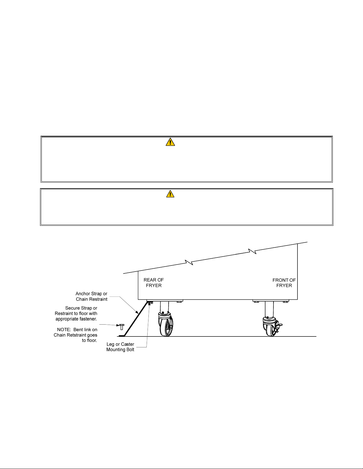
Adequate means must be provided to limit the movement of this appliance without depending
upon the gas line connection. Single fryers equipped with legs must be stabilized by installing
anchor straps. All fryers equipped with casters must be stabilized by installing restraining
chains. If a flexible gas line is used, an additional restraining cable must be connected at all
times when the fryer is in use.
DANGER
The front ledge of the fryer is not a step! Do not stand on the fryer. Serious injury can result
from slips or contact with the hot oil.
DANGER
Do not store or use gasoline or other flammable liquids or vapors in the vicinity of this or any
other appliance.
DANGER
Instructions to be followed in the event the operator smells gas or otherwise detects a gas leak
must be posted in a prominent location. This information can be obtained from the local gas
company or gas supplier.
DANGER
This product contains chemicals known to the state of California to cause cancer and/or birth
defects or other reproductive harm.
Operation, installation, and servicing of this product could expose you to airborne particles of
glasswool or ceramic fibers, crystalline silica, and/or carbon monoxide. Inhalation of airborne
particles of glasswool or ceramic fibers is known to the State of California to cause cancer.
Inhalation of carbon monoxide is known to the State of California to cause birth defects or other
reproductive harm.
DANGER
The crumb tray in fryers equipped with a filter system must be emptied into a fireproof container
at the end of frying operations each day. Some food particles can spontaneously combust if left
soaking in certain shortening material.
WARNING
Do not bang fry baskets or other utensils on the fryer’s joiner strip. The strip is present to seal
the joint between the fry vessels. Banging fry baskets on the strip to dislodge shortening will
distort the strip, adversely affecting its fit. It is designed for a tight fit and should only be
removed for cleaning.
NOTICE
The Commonwealth of Massachusetts requires any and all gas products to be installed by a
licensed plumber or pipe fitter.
iii
Page 4
PROTECTOR® SERIES GAS FRYER
CHAPTER 1: GENERAL INFORMATION
1.1 Applicability and Validity
The Protector® Series Gas Fryer with SMART4U® technology has been approved by the
European Union for sale and installation in the following EU countries: AT, BE, DE, DK, ES,
FI, FR, GB, IE, IT, LU, NL, NO, PT and SE.
This manual is applicable to and valid for all Protector® Series Gas Fryers sold in Englishspeaking countries, including those in the European Union. Where conflicts exist between instructions and information in this manual and local or national codes of the country in which
the equipment is installed, installation and operation shall comply with those codes.
This appliance is only for professional use and shall be used by qualified personnel only, as
defined in Section 1.7.
1.2 Safety Information
Before attempting to operate your unit, read the instructions in this manual thoroughly. Throughout
this manual, you will find notations enclosed in double-bordered boxes similar to the ones that
follow.
CAUTION
CAUTION boxes contain information about actions or conditions that may cause or result
in a malfunction of your system.
WARNING
WARNING boxes contain information about actions or conditions that may cause or result
in damage to your system, and which may cause your system to malfunction.
DANGER
DANGER boxes contain information about actions or conditions that may cause or result
in injury to personnel, and which may cause damage to your system and/or cause your
system to malfunction.
Your fryer is equipped with automatic safety features:
1. High temperature detection shuts off gas to the burner assembly should the controlling
thermostat fail.
2. An optional safety switch built into the drain valve prevents burner ignition with the drain valve
even partially open.
1-1
Page 5

1.3 Computer Information for the CM7 Computers
FCC COMPLIANCE
This equipment has been tested and found to comply with the limits for a Class A digital device, pursuant to Part 15 of the FCC rules. While this device is a verified Class A device, it has been shown
to meet the Class B limits. These limits are designed to provide reasonable protection against harmful interference when the equipment is operated in a commercial environment. This equipment
generates, uses and can radiate radio frequency energy and, if not installed and used in accordance
with the instruction manual, may cause harmful interference to radio communications.
Operation of the equipment in a residential area is likely to cause harmful interference in which case
the user will be required to correct the interference at his own expense.
The user is cautioned that any changes or modifications not expressly approved by the party responsible for compliance could void the user's authority to operate the equipment.
If necessary, the user should consult the dealer or an experienced radio and television technician for
additional suggestions.
The user may find the following booklet prepared by the Federal Communications Commission
helpful: "How to Identify and Resolve Radio-TV Interference Problems". This booklet is available
from the U.S. Government Printing Office, Washington, DC 20402, Stock No. 004-000-00345-4.
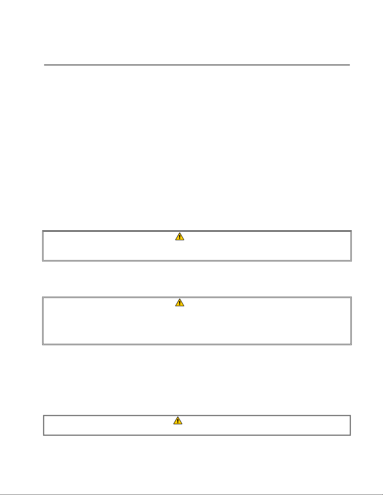
1.4 European Community (CE) Specific Information
The European Community (CE) has established certain specific standards regarding equipment of
this type. Whenever a conflict exists between CE and non-CE standards, the information or
instructions concerned are identified by means of shadowed boxes similar to the one below.
Non-CE Standard
for Inco ming Gas Pre ssur es
Type Minimum Maximum
6" W.C. 14" W.C.
Na tu r a l 1.4 9 k P a 3.49 kP a
14.68 mbar 34.72 mbar
11" W .C. 14" W .C .
LP 2.74 kPa 3.49 kPa
27.28 mbar 34.84 mbar
1-2
Page 6

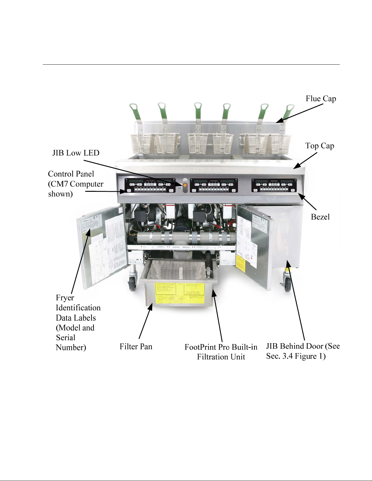
1.5 Equipment Description
Protector® Series high-efficiency gas fryers employ a unique infrared burner system that uses up to
43% less energy to cook the same volume as conventional open-burner fryers. Models in this series
include FPGL30 variants. FPGL30 models have a built-in FootPrint Pro filtration system located
under the leftmost two fryers
in a battery.
All Protector
®
Series Gas fryers are of an open-frypot design with no tubes and have a hand-sized
opening into the cold zone, which makes cleaning the stainless frypot quick and easy.
Heating is supplied by a pair of infrared burner assemblies mounted on each side of the frypot.
Combustion air for the burners is supplied by a dedicated blower mounted on the front of the frypot.
Protector® Series Gas fryers can be configured for natural gas, propane (LP), or manufactured gas,
as required by the customer.
Each frypot is equipped with a temperature probe for precise temperature control.
All Protector® Series Gas fryers come standard with electronic ignition, melt cycle and boil-out
mode. The Protector® Series Gas fryers are controlled with a CM-7 computer. Fryers in this series
come in full pot arrangements, and can be purchased as two, three or four vat fryers.
All fryers in this series require an external source of AC electrical power. Units can be configured
for voltages ranging from 100 VAC to 240 VAC.
FPGL30 fryers are shipped completely assembled. All fryers are shipped with a package of standard
accessories. Each fryer is adjusted, tested, and inspected at the factory before crating for shipment.
1.6 Installation, Operating, and Service Personnel
Operating information for Frymaster equipment has been prepared for use by qualified and/or
authorized personnel only, as defined in Section 1.7. All installation and service on Frymaster
equipment must be performed by qualified, certified, licensed, and/or authorized installation
or service personnel, as defined in Section 1.7.
1.7 Definitions
QUALIFIED AND/OR AUTHORIZED OPERATING PERSONNEL
Qualified/authorized operating personnel are those who have carefully read the information in this
manual and have familiarized themselves with the equipment functions, or who have had previous
experience with the operation of the equipment covered in this manual.
1-3
Page 7

QUALIFIED INSTALLATION PERSONNEL
Qualified installation personnel are individuals, firms, corporations, and/or companies which, either
in person or through a representative, are engaged in and are responsible for the installation of gasfired appliances. Qualified personnel must be experienced in such work, be familiar with all gas
precautions involved, and have complied with all requirements of applicable national and local
codes.
QUALIFIED SERVICE PERSONNEL
Qualified service personnel are those who are familiar with Frymaster equipment and who have been
authorized by Frymaster, L.L.C. to perform service on the equipment. All authorized service
personnel are required to be equipped with a complete set of service and parts manuals, and to stock
a minimum amount of parts for Frymaster equipment. A list of Frymaster Factory Authorized
Service Centers (FASC) is included with the fryer when shipped from the factory. Failure to use
qualified service personnel will void the Frymaster warranty on your equipment.
1.8 Shipping Damage Claim Procedure
Your Frymaster equipment was carefully inspected and packed before leaving the factory. The
transportation company assumes full responsibility for safe delivery upon its acceptance of the
equipment for transport.
What to do if your equipment arrives damaged:
1. File a claim for damages immediately, regardless of the extent of damages.
2. Inspect for and record all visible loss or damage, and ensure that this information is noted on
the freight bill or express receipt and is signed by the person making the delivery.
3. Concealed loss or damage that was unnoticed until the equipment was unpacked should be
recorded and reported to the freight company or carrier immediately upon discovery. A
concealed damage claim must be submitted within 15 days of the date of delivery. Ensure that
the shipping container is retained for inspection.
Frymaster
DOES NOT ASSUME RESPONSIBILITY FOR DAMAGE OR LOSS
INCURRED IN TRANSIT.
1.9 Parts Ordering and Service Information
In order to assist you quickly, the Frymaster Factory Authorized Service Center (FASC) or Service
Department representative requires certain information about your equipment. Most of this
information is printed on a data plate affixed to the inside of the fryer door. Part numbers are found
in the Service and Parts Manual. Parts orders may be placed directly with your local FASC or
distributor. Included with fryers when shipped from the factory is a list of Frymaster FASCs. If you
do not have access to this list, contact the Frymaster Service Department at 1-800-551-8633 or 1318-865-1711 or by e-mail: service@frymaster.com
.
1-4
Page 8

When ordering parts, the following information is required:
Model Number:
Serial Number:
Type of Gas or Voltage:
Item Part Number:
Quantity Needed:
Service information may be obtained by contacting your local FASC/Distributor. Service may also
be obtained by calling the Frymaster Service Department at 1-800-551-8633 or 1-318-865-1711 or
by e-mail: service@frymaster.com
. When requesting service, please have the following information
ready:
Model Number:
Serial Number:
Type of Gas:
In addition to the model number, serial number, and type of gas, please be prepared to describe the
nature of the problem and have ready any other information that you think may be helpful in solving
your problem.
RETAIN AND STORE THIS MANUAL IN A SAFE PLACE FOR FUTURE USE.
1-5
Page 9
PROTECTOR® SERIES GAS FRYER
CHAPTER 2: INSTALLATION INSTRUCTIONS
2.1 General Installation Requirements
Qualified, licensed, and/or authorized installation or service personnel, as defined in Section
1.7 of this manual, should perform all installation and service on Frymaster equipment.
Conversion of this appliance from one type of gas to another should only be performed by
qualified, licensed, and/or authorized installation or service personnel as defined in Section 1.7
of this manual.
Failure to use qualified, licensed, and/or authorized installation or service personnel (as defined in Section 1.7 of this manual) to install, convert to another gas type or otherwise service
this equipment will void the Frymaster warranty and may result in damage to the equipment
or injury to personnel.
Where conflicts exist between instructions and information in this manual and local or national codes or regulations, installation and operation shall comply with the codes or regulations in force in the country in which the equipment is installed.
DANGER
Building codes prohibit a fryer with its open tank of hot oil being installed beside an
open flame of any type, including those of broilers and ranges.
Upon arrival, inspect the fryer carefully for visible or concealed damage. (See Shipping Damage
Claim Procedure in Chapter 1.)
DANGER
Frymaster appliances equipped with legs are for stationary installations. Appliances
fitted with legs must be lifted during movement to avoid damage to the appliance
and bodily injury. For movable installations, optional equipment casters must be
used. Questions? Call 1-800-551-8633.
2.1.1 Clearance and Ventilation
The fryer(s) must be installed with a 6” (150 mm) clearance at both sides and back when installed
adjacent to combustible construction; no clearance is required when installed adjacent to
noncombustible construction. A minimum of 24” (600 mm) clearance should be provided at the
front of the fryer.
WARNING
Do not block the area around the base or under the fryers.
2-1
Page 10
DANGER
No structural material on the fryer should be altered or removed to accommodate
placement of the fryer under a hood. Questions? Call the Frymaster Dean Service
Hotline at 1-800-551-8633.
One of the most important considerations of efficient fryer operation is ventilation. Make sure the
fryer is installed so that products of combustion are removed efficiently, and that the kitchen
ventilation system does not produce drafts that interfere with burner operation.
The fryer flue opening must not be placed close to the intake of the exhaust fan, and the fryer must
never have its flue extended in a “chimney” fashion. An extended flue will change the combustion
characteristics of the fryer, causing longer recovery time. It also frequently causes delayed ignition.
To provide the airflow necessary for good combustion and burner operation, the areas surrounding
the fryer front, sides, and rear must be kept clear and unobstructed.
DANGER
This appliance must be installed with sufficient ventilation to prevent the occurrence
of unacceptable concentrations of substances harmful to the health of personnel in
the room in which it is installed.
Fryers must be installed in an area with an adequate air supply and adequate ventilation. Adequate
distances must be maintained from the flue outlet of the fryer to the lower edge of the ventilation
filter bank. Filters should be installed at an angle of 45º. Place a drip tray beneath the lowest edge
of the filter. For U.S. installation, NFPA standard No. 96 states, “A minimum distance of 18 in.
(450 mm) should be maintained between the flue outlet and the lower edge of the grease filter.”
Frymaster recommends that the minimum distance be 24 in. (600 mm) from the flue outlet to the
bottom edge of the filter when the appliance consumes more than 120,000 BTU per hour.
For installations in the United States, information on construction and installation of ventilating
hoods can be found in the NFPA standard cited above. A copy of the standard may be obtained
from the National Fire Protection Association, Battery March Park, Quincy, MA 02269.
2.1.2 National Code Requirements
The type of gas for which the fryer is equipped is stamped on the data plate attached to the inside of
the fryer door. Connect a fryer stamped “NAT” only to natural gas, those stamped “PRO” only to
propane gas, and those stamped “MFG” only to manufactured gas.
Installation shall be made with a gas connector that complies with national and local codes, and,
where applicable, CE codes. Quick-disconnect devices, if used, shall likewise comply with national,
local, and, if applicable, CE codes. In the absence of local codes, installation must conform to the
national Fuel Gas Code, ANSI Z223.1/NFPA 54 or the Natural Gas and Propane Installation code,
CSA B149.1, as applicable including:
1. The appliance and its individual shutoff valve must be disconnected form the gas supply piping
system during any pressure testing of the system at test pressures in excess of ½ psi (3.5 kPa).
2-2
Page 11
2. The appliance must be isolated from the gas supply piping system by closing its individual
manual shutoff valve during any pressure testing of the gas supply piping system at test
pressures equal to or less than ½ psi (3.5 kPa).
2.1.3 Electrical Grounding Requirements
All electrically operated appliances must be grounded in accordance with all applicable national and
local codes, and, where applicable, CE codes. In the absence of local codes, the appliance must be
grounded in accordance with National Electrical Code, ANSI/NFPA 70, or the Canadian Electrical
Code, CSA C22.2, as applicable. All units (cord connected or permanently connected) should be
connected to a grounded power supply system. A wiring diagram is located on the inside of the
fryer door. Refer to the rating plate on the inside of the fryer door for proper voltages.
DANGER
This appliance is equipped with a special (grounding) plug for your protection
against electrical shock, and must be plugged directly into a properly grounded receptacle. Do not cut, remove, or otherwise bypass the grounding prong on this
plug!
DANGER
This appliance requires electrical power for operation. Place the gas control valve in
the OFF position in case of a prolonged power outage. Do not attempt to operate
this appliance during a power outage.
2.1.4 Australian Requirements
To be installed in accordance with AS 5601 / AG 601, local authority, gas, electricity, and any other
relevant statutory regulations.
2.2 Caster/Leg Installation
Depending upon the specific configuration ordered, your fryer may have been shipped without
installed casters or legs. DO NOT INSTALL THIS APPLIANCE WITHOUT CASTERS OR
LEGS. If the appliance requires the installation of casters or legs, install them in accordance
with the instructions included in your accessory package.
On an appliance with casters; the installation shall be made with a connector that complies with the
Standard for Moveable Gas Appliances, ANSI Z21.69 • CSA 6.16, and a quick disconnect device
that complies with the Standard for Quick-Disconnect Devices for Use With Gas Fuel, ANSI Z21.41
• CSA 6.9.
2.3 Pre-Connection Preparations
DANGER
DO NOT connect this appliance to the gas supply before completing each step in
this section.
2-3
Page 12
After the fryer has been positioned under the exhaust hood, ensure the following has been
e
e
(1)
O
accomplished:
1. Adequate means must be provided to limit the movement of fryers without depending upon the
gas line connections. If a flexible gas hose is used, a restraining cable must be connected at all
times when the fryer is in use. The restraining cable and installation instructions are packed with
the flexible hose in the accessories box that was shipped with your unit.
DANGER
Do not attach an apron drainboard to a single fryer. The fryer may become unstable,
tip over, and cause injury. The appliance area must be kept free and clear of
combustible material at all times.
2. Level fryers equipped with legs by screwing out the legs approximately 1 inch then adjusting
them so that the fryer is level and at the proper height in the exhaust hood. Frymaster
recommends that the minimum distance from the flue outlet to the bottom edge of the hood be 24
in. (600 mm) when the appliance consumes more than 120,000 BTU per hour. NOTE: There
are no built-in leveling devices on fryers equipped with casters. The floor where the fryer is to
be installed must be level.
3. Test the fryer electrical system:
a. Plug the fryer electrical cord(s) into a grounded electrical receptacle.
b. Place the power switch in the ON position. Verify that the display indicates CYCL.
c. Place the fryer power switch in the OFF position. Verify that the display indicates OFF.
4. Refer to the data plate on the inside of the fryer door to determine if the fryer burner is configured
for the proper type of gas before connecting the fryer quick-disconnect device or piping from the
gas supply line.
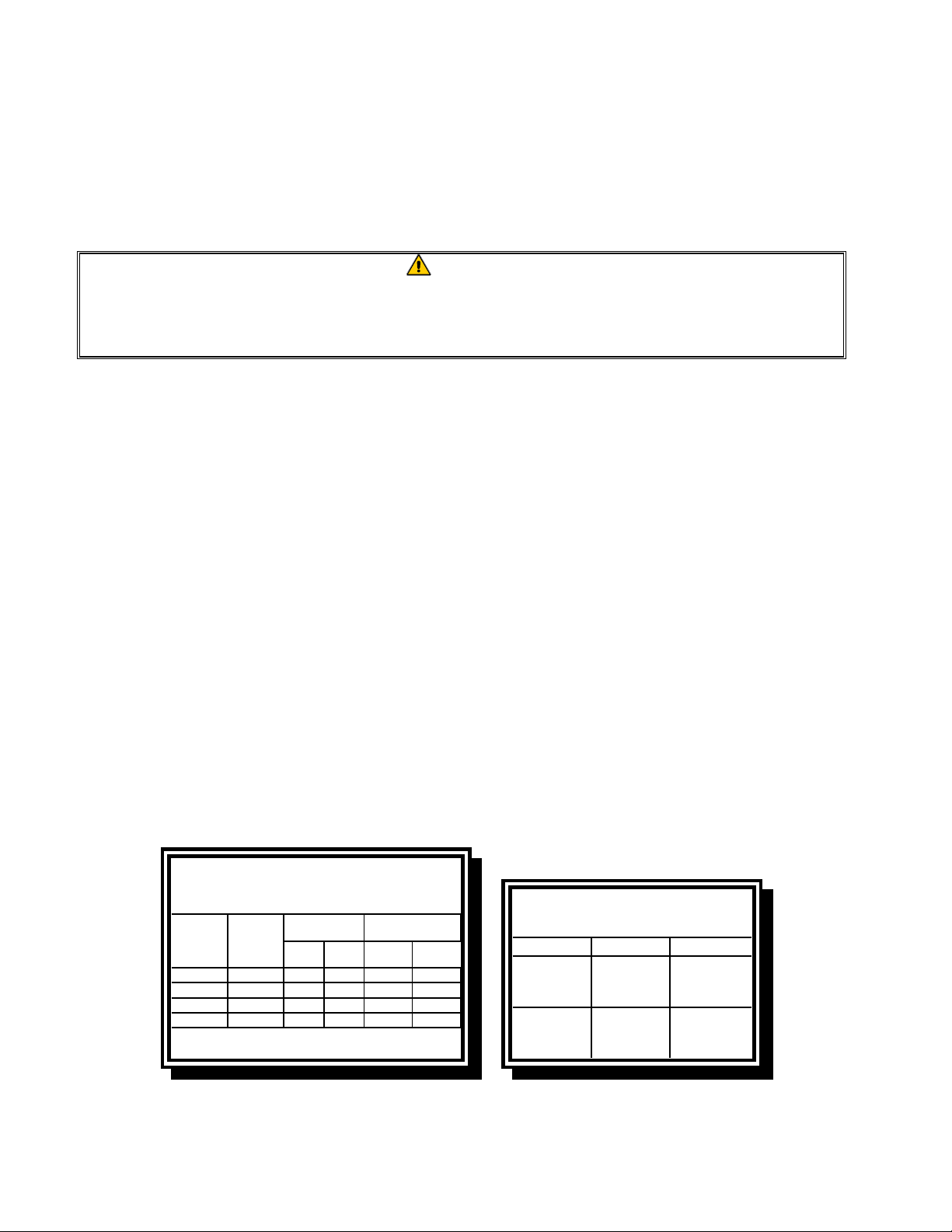
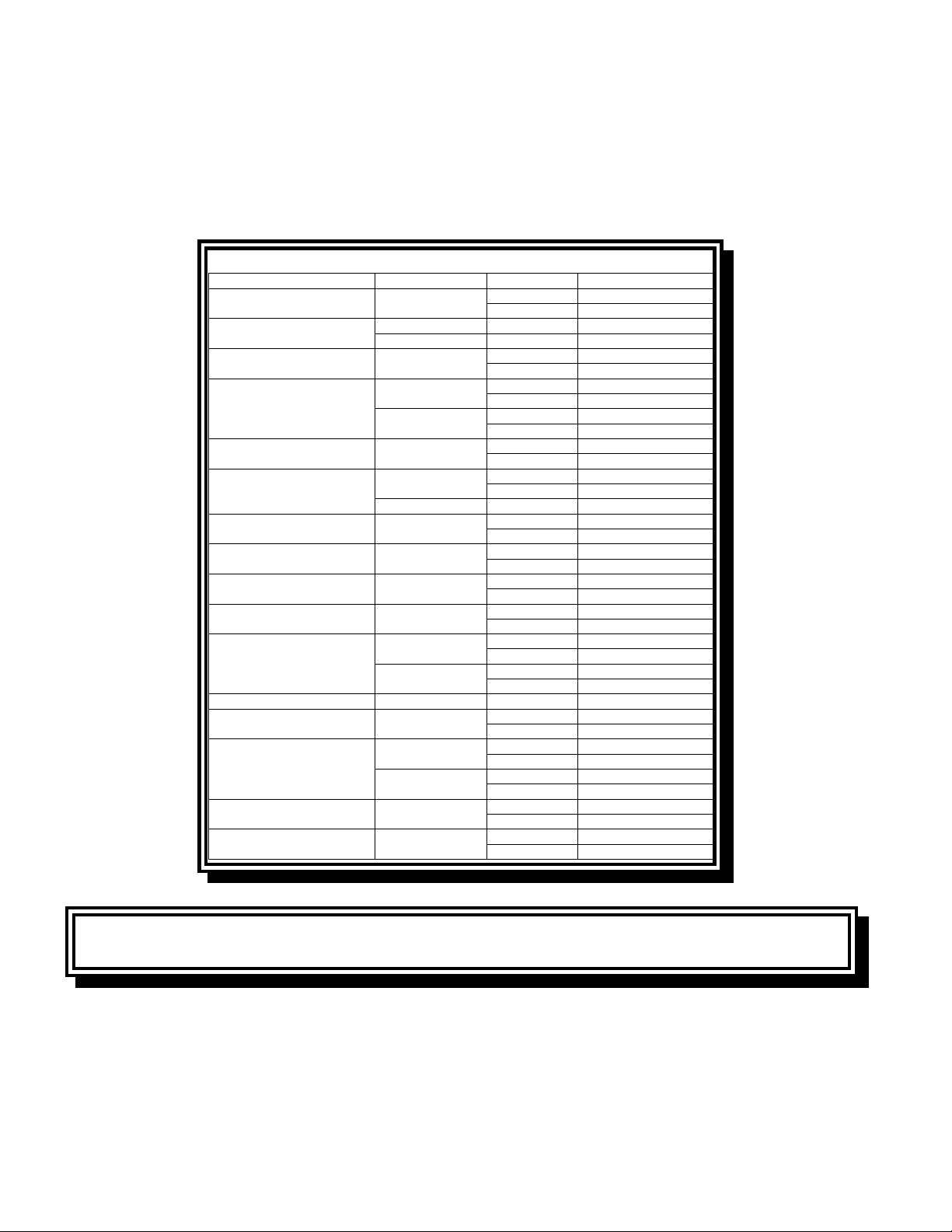
5. Verify the minimum and maximum gas supply pressures for the type of gas to be used in
accordance with the accompanying tables.
CE Standard
for Incoming Gas Pressures
for Fryers Manufactured After April 1999
Pressure
Gas
G20 20 2 x 3.40 2 x 3.40 7 mbar 7 mbar
G25 20 or 25 2 x 3.40 2 x 3.40 10 mbar 10 mbar
G30 28/30 or 50 2 x 2.05 2 x 2.05 17 mbar 17 mbar
G31 37 or 50 2 x 2.05 2 x 2.05 20 mbar 20 mbar
mbar = 10,2 mm H
(mbar)
Orifice Diameter
Singl
(1)
Vat
2
Dual
Vat
Regulator Pressure
Singl
Vat
Dual
Vat
Non-CE Standard
for Incoming Gas Pressures
Gas Minimum Maximum
Natural
LP
6" W.C.
1.49 kPa
14.93 mbar
11" W.C.
2.74 kPa
27.37 mbar
14" W.C.
3.48 kPa
34.84 mbar
14" W.C.
3.48 kPa
34.84 mbar
6. For fryers equipped with a FootPrint Pro system or basket lifts, plug the electrical cord(s) into a
power receptacle behind the fryer.
2-4
Page 13
2.4 Connection to Gas Line
DANGER
Before connecting new pipe to this appliance, the pipe must be blown out thoroughly to remove all foreign material. Foreign material in the burner and gas controls will cause improper and dangerous operation.
DANGER
The appliance and its individual shutoff valve must be disconnected from the gas
supply piping system during any pressure testing of the system at test pressures in
excess of ½ PSI (3.45 kPa, 13.84 inches W.C.) to avoid damage to the fryer’s gas
tubes and gas valve(s).
DANGER
The appliance must be isolated from the gas supply piping system by closing its individual manual shutoff valve during any pressure testing of the gas supply piping
system at test pressures equal to or less than ½ PSI (3.45 kPa, 13.84 inches W.C.)
DANGER
“Dry-firing” your unit will cause damage to the frypot and can cause a fire. Always
ensure that cooking oil or water is in the frypot before firing the unit.
DANGER
All connections must be sealed with a joint compound suitable for the gas being
used and all connections must be tested with a solution of soapy water before lighting any pilots.
Never use matches, candles, or any other ignition source to check for leaks. If gas
odors are detected, shut off the gas supply to the appliance at the main shut-off
valve and immediately contact the local gas company or an authorized service
agency for service.
The size of the gas line used for installation is very important. If the line is too small, the gas
pressure at the burner manifold will be low. This may cause slow recovery and delayed ignition.
The incoming gas supply line should be a minimum of 1½” (38 mm) in diameter. Refer to the chart
below for the minimum sizes of connection piping.
Gas Connection Pipe Sizes
(Minimum incoming pipe size should be 1 1/2" (41 mm))
4 or more
Gas Single Unit 2 - 3 Units
3/4
Natural
Propane 1/2" (15 mm) 3/4" (22 mm) 1" (28 mm)
Manufactured 1" (28 mm) 1 1/4" (36 mm) 1 1/2" (41 mm)
" (22 mm)
1" (28 mm) 1 1/4" (36 mm)
units*
2-5
Page 14
* For distances of more than 20 feet (6 m) and/or more
than 4 fittings or elbows, increase the connection by one
pipe size.
The Protector® Series gas fryer has received the CE mark for the countries and gas categories
indicated in the table below. NOTE: The nominal heat input (QN) is 21kW except for AT, DE, LU
and category 3P/B, which is 23kW.
COUNTRIES CATEGORIES GAS PRESSURE (MBAR)
AUSTRIA (AT) II2H3B/P
BELGIUM (BE)
DENMARK (DK) II2H3B/P
FRANCE (FR)
FINLAND (FI) II2H3B/P
GERMANY (DE)
GREECE (GR) II2H3+
ITALY (IT) II2H3+
IRELAND (IE) II2H3+
LUXEMBOURG (LU) II2E3B/P
NETHERLANDS (NL)
NORWAY (NO) I3B/P G30, G31 30
PORTUGAL (PT) II2H3+
SPAIN (ES)
SWEDEN (SE) II2H3B/P
UNITED KINGDOM (UK) II2H3+
CE Approved Gas Categories by Country
G20 20
I2E(R)B G20, G25 20, 25
I3+ G30, G31 28-30, 37
II2Esi3+
II2Esi3P
II2ELL3B/P
I3P G31 50
II2L3P
II2L3B/P
II2H3+
II2H3P
G30, G31 50
G20 20
G30, G31 30
G20, G25 20, 25
G30, G31 28-30, 37
G20, G25 20, 25
G31 50
G20 20
G30, G31 30
G20, G25 20
G30, G31 50
G20 20
G30, G31 28-30, 37
G20 20
G30, G31 28-30, 37
G20 20
G30, G31 28-30, 37
G20 20
G30, G31 50
G25 25
G31 50
G25 25
G30, G31 30
G20 20
G30, G31 28-30, 37
G20 20
G30, G31 28-30, 37
G20 20
G31 37, 50
G20 20
G30, G31 30
G20 20
G30, G31 28-30, 37
CE Standard
Required airflow for the combustion air supply is 2m3/h per kW.
1. Connect the quick-disconnect hose to the fryer quick-disconnect under the fryer and to the
building gas line.
NOTE: Some fryers are configured for a rigid connection to the gas supply line. These units
are connected to the gas supply line at the rear of the unit.
2-6
Page 15
When using thread compound, use very small amounts on male threads only. Use a pipe thread
compound that is not affected by the chemical action of LP gases (Loctite™ PST56765 Sealant
is one such compound). DO NOT apply compound to the first two threads. Doing so may allow
some of the compound to enter the gas stream, resulting in clogging of burner orifices and/or the
control valve.
2. Open the gas supply to the fryer and check all piping, fittings, and gas connections for leaks. A
soap solution should be used for this purpose.
3. Close the fryer drain valve and fill the frypot with water and boil-out solution to the bottom
OIL LEVEL line at the rear of the frypot. Light the fryer and perform the boil-out procedures
that are described in the “Lighting Instructions” and “Boiling Out the Frypot” topics found in
Chapter 3 of this manual.
DANGER
“Dry-firing” your unit will cause damage to the frypot and can cause a fire. Always
ensure that melted shortening, cooking oil, or water is in the frypot before firing your
unit.
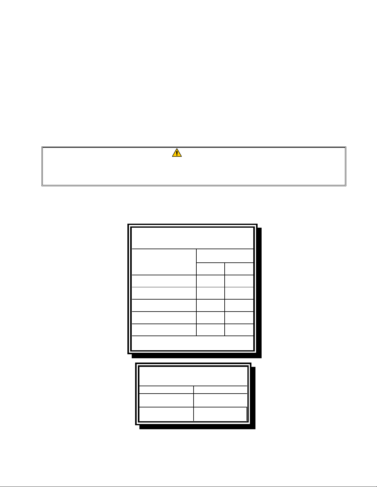
4. The burner manifold pressure should be checked at this time by the local gas company or an
authorized service agent. The tables below and on the following page list the burner manifold
gas pressures for the various gas types that can be used with this equipment.
CE Standard
Burner Manifold Gas Pressures
for Fryers Manufactured After April 1999
Pressure (mbar)
Single
Gas
Natural Gas Lacq
(G20) under 20 mbar
Natural Gas Groningue *
(G25) under 25 mbar
Natural Gas Groningue
(G25) under 20 mbar
Butane
(G30) at 28/30 or 50 mbar
Propane
(G31) under 37 or 50 mbar
* Belgian G25 = 7,0 mbar (single or dual)
Vat
77
10 10
10 10
17 17
20 20
Non-CE Standard
Burner Manifold Gas Pressures
Gas Pressure
Natural
Propane
3" W.C.
0.73 kPa
8.25" W.C.
2.5 kPa
Dual
Vat
5. Check the programmed temperature thermostat setting. (Refer to chapter 4 CM7 Computer
Instructions) for the setpoint programming instructions for your particular controller.)
2-7
Page 16
2.5 Converting to another Gas Type
DANGER
This appliance was configured at the factory for a specific type of gas. Converting from
one type of gas to another requires the installation of specific gas-conversion components. Conversion instructions are included with conversion kits.
Switching to a different type of gas without installing the proper conversion components
may result in fire or explosion. NEVER ATTACH THIS APPLIANCE TO A GAS SUPPLY
FOR WHICH IT IS NOT CONFIGURED!
Conversion of this appliance from one type of gas to another should only be performed
by qualified, licensed, and authorized installation or service personnel, as defined in
Section 1.7 of this manual.
Protector
®
Series gas fryers manufactured for non-CE countries use different burners for each type gas.
The burners in fryers built for Propane gas have a special gray-colored coating on the burner tiles to
enable them to withstand the higher caloric value of the Propane gas. Burners designed for use in
propane units may be used in natural gas applications, but not vice versa.
Non-CE Gas Conversion Kits
Natural Gas to Propane (LP) Gas Propane (LP) Gas to Natural Gas
Full Vat: Part Number 826-2527 Full Vat: Part Number 826-2528
Dual Vat: Part Number 826-2529 Dual Vat: Part Number 826-2530
Units manufactured for export to CE countries are equipped with “universal” burners that may be used
with either Natural (G20, G25) gas or Butane (G30) and Propane (G31) gasses.
CE Gas Conversion Kits for Units with Gas Valve 810-1715
G20 or G25 (Natural) to G30 or G31 Gas: G30 or G31 to G20 or G25 (Natural) Gas:
Part Number 826-1196 Part Number 826-1197
CE GAS CONVERSION INSTRUCTIONS
1. Between G20- and G25-type Natural Gas, adjust the gas pressure at the regulator. (Refer to the CE
Standard Burner Manifold Gas Pressure Chart.) Do not change the orifice.
2. Between a 2nd family (G20 or G25) and a 3rd family gas (G30 Butane or G31 Propane):
a. Change the orifices.
b. Adjust the manifold pressure.
3. Remove the old rating plate and return to Frymaster. Affix the new rating plate included with the
conversion kit in place of the old rating plate stating the gas has been converted.
4. If the destination language changes, replace the rating plate. Call your local service agency or KES
for a label kit. The language of reference will be on the corner of the label.
2-8
Page 17
2.6 Positioning the Fryer
1. Once the fryer has been positioned at the frying station, use a carpenter’s level placed across the
top of the frypot to verify that the unit is level, both side-to-side and front-to-back.
To level fryers, adjust the casters being careful to ensure the fryer(s) are at the proper height in
the frying station.
When the fryer is leveled in its final position, install the restraints provided by the KES to limit
its movement so that it does not depend on or transmit stress to the connection. Install the restraints in accordance with the provided instructions. If the restraints are disconnected for service
or other reasons, they must be reconnected before the fryer is used.
DANGER
Hot oil can cause severe burns. Avoid contact. Under all circumstances, oil must be
removed from the fryer before attempting to move it to avoid spills, falls, and severe
burns. Fryers may tip and cause personal injury if not secured in a stationary position.
DANGER
Adequate means must be provided to limit the movement of this appliance without
depending on the connector and the quick-disconnect device or its associated piping to limit the appliance movement.
2. Close fryer drain-valve(s) and fill frypot with water to the bottom oil level line.
3. Boil out frypot(s) in accordance with the instructions in Section 4.11 on page 4-16 of this man-
ual.
4. Drain, clean, and fill frypot(s) with cooking oil. (See Equipment Setup and Shutdown Proce-
dures in Chapter 3.)
2-9
Page 18
PROTECTOR® SERIES GAS FRYER
CHAPTER 3: OPERATING INSTRUCTIONS
FINDING YOUR WAY AROUND THE PROTECTOR® SERIES GAS FRYER
3-1
Page 19
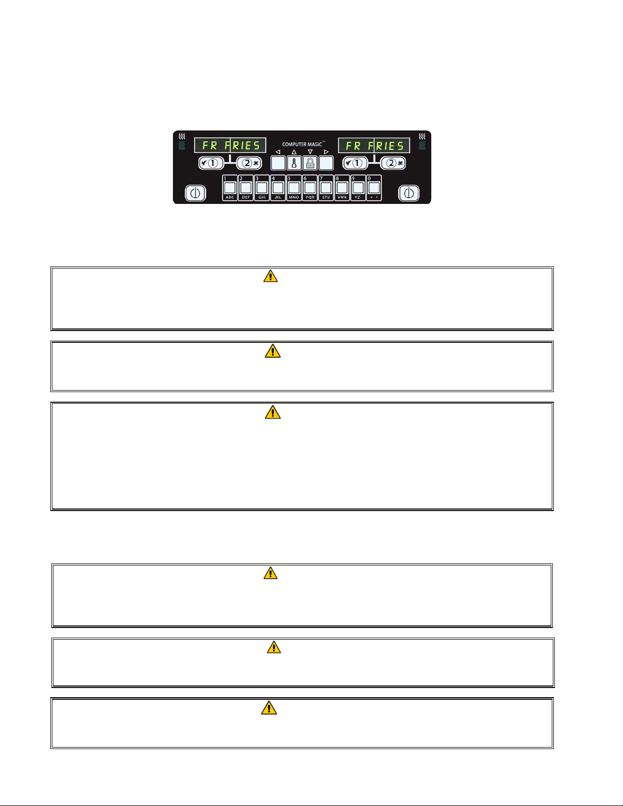
3.1 Controller Operation and Programming
Protector® Series gas fryers are equipped with CM-7 computers (illustrated below). Refer to the
CM7 Computer Operating Instructions in Chapter 4 for the computer programming and operating
procedures.
CM7 COMPUTER
3.2 Equipment Setup and Start-Up Procedures
WARNING
The on-site supervisor is responsible for ensuring that operators are made aware of
the inherent hazards of operating a hot oil filtering system, particularly the aspects
of oil filtration, draining and cleaning procedures.
CAUTION
If this is the first time the fryer is being used after installation, refer to Section 4.11
on page 4-16 for the boil-out procedure.
CAUTION
The cooking oil capacity of the Protector™ Series gas fryer is 32 lbs. (3.8
gallons/14.5 liters) at 70°F (21°C) for a full-vat.
Before lighting the fryer, make sure the fryer is OFF and the frypot drain valve(s)
is/are closed. Remove the basket support rack(s), if installed, and fill the frypot to
the bottom OIL-LEVEL line.
3.2.1 Setup
WARNING
Never operate this appliance with an empty frypot. The frypot must be filled with water or oil before lighting the burners. Failure to do so will damage the frypot and may
cause a fire.
DANGER
Remove all drops of water from the frypot before filling with oil. Failure to do so will
cause spattering of hot liquid when the oil is heated to cooking temperature.
WARNING
The Protector™ is not intended to use solid shortening. Use only liquid shortening
with this fryer. The use of solid shortening will clog the top off oil lines.
3-2
Page 20
1. Fill the frypot with cooking oil to the bottom OIL LEVEL line located on the rear of the frypot.
This will allow for oil expansion as heat is applied. Do not fill cold oil any higher than the bottom line; overflow may occur as heat expands the oil.
2. Ensure that the power cord(s) are plugged into the appropriate receptacle(s). Verify that the face
of the plug is flush with the outlet plate, with no portion of the prongs visible.
3. Ensure that the oil level is at the top OIL LEVEL line when the oil is at its cooking temperature.
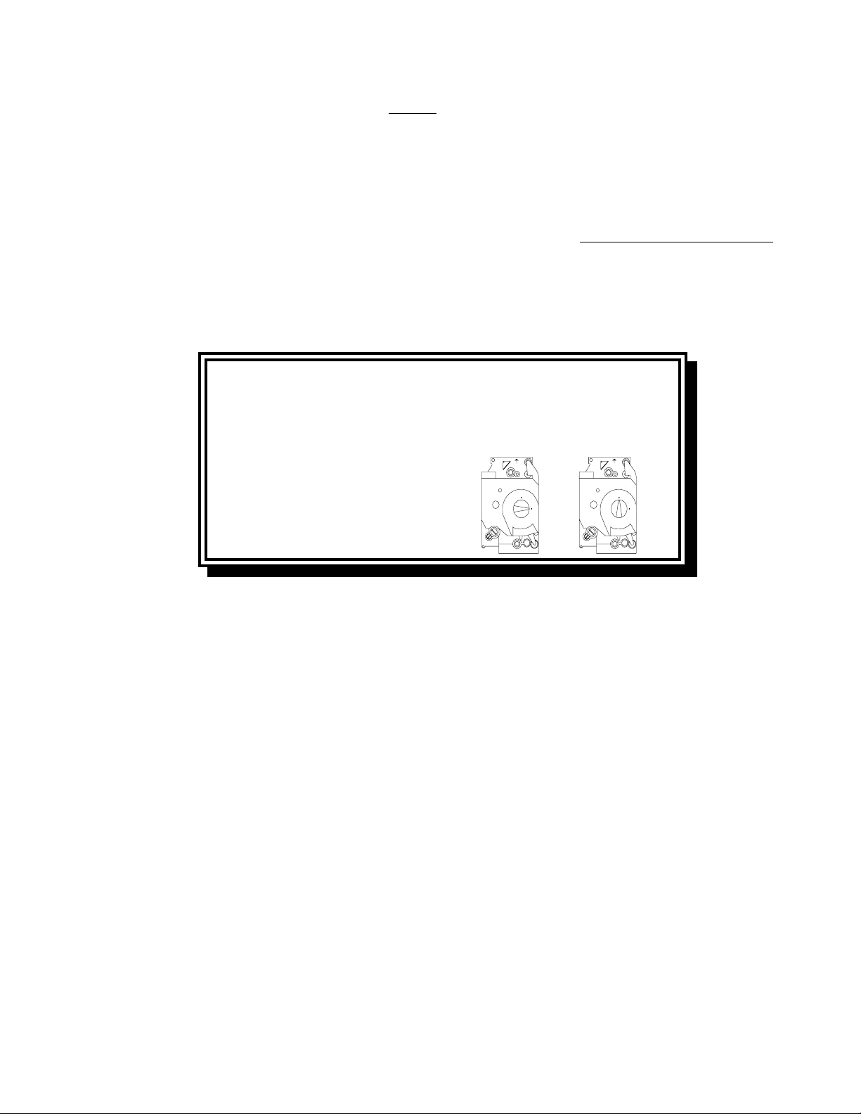
3.2.2 Lighting the Fryer
1. Press the computer ON/OFF switch to the OFF position.
For CE Fryers
Placing the ON/OFF switch in the OFF
position a ls o turns off the gas valve. Wait five
minutes before continui ng with Step 2, which
will a lso tu r n o n th e g a s valv e .
After placing the ON/OFF switch in the OFF
posit i on, t ur n t he gas v al ve knob t o t he OFF
position. Wait 5 minutes, then turn the knob
to the ON p o stion an d pro c e e d with S te p 2 .
For Non-CE Fryers
ON
Honeywell
OFF
ON
Honeywell
OFF
2. Press the computer ON/OFF switch to the ON position and set the thermostat or program the
computer for normal cooking temperature.
3. If the burners fail to light, press the ON/OFF switch to the OFF position and wait 60 seconds.
Repeat step 2.
4. The fryer will automatically enter the melt cycle mode if the frypot temperature is below 180ºF
(82ºC). (NOTE: During the melt cycle, the burners will repeatedly fire for a few seconds, then
go out for a longer period.) When the frypot temperature reaches 180ºF (82ºC), the unit will
automatically switch to the heating mode. The burners will remain lit until the frypot
temperature reaches the programmed cooking temperature.
5. After the burners have been lit for at least 90 seconds, observe the flames through the burner
viewing ports located on each side of the combustion air blower.
3-3
Page 21

Left Viewing Ports are
Right Viewing Ports
behind the motor
housings.
The optimum burn is a bright orange-red glow. If a blue flame is observed, or if there are dark spots
on a burner face, adjust the air gas mixture as follows: On the side of the blower housing opposite
the motor is a plate with a locking nut. Loosen the nut enough to allow the plate to be moved, then
adjust the position of the plate to open or close the air intake opening until a bright orange-red glow
is obtained. Carefully hold the plate in position and tighten the locking nut.
3.3 Boiling Out the Frypot
To ensure that the frypot is free of any contamination resulting from its manufacture, shipping, and
handling during installation, the frypot must be boiled out before first use. Refer to page 4-16 for
this procedure.
3.4 Shutting the Fryer Down
For short-term shut down during the workday, place the computer ON/OFF switch in the OFF
position and put the frypot covers in place (if the fryer is so equipped).
When shutting the fryers down at closing time, place the computer ON/OFF switch in the OFF
position. Then place the gas valve in the off position. See illustration below.
For CE Fryers
Placi ng t he ON/OFF s wit ch in the OFF
position also turns off the gas valve.
After placi ng th e ON/OFF swit ch in the OFF
position, t urn the gas valve knob to the OFF
position.
Put the frypot covers in place (if the fryer is so equipped).
3-4
For Non-CE Fryers
ON
Honeywell
OFF
ON
Honeywell
OFF
Page 22

3.5 Oil Attendant™ Automatic Top-Off
Oil is continually topped off in the frypots
from a reservoir in the cabinet. The
reservoir holds a 35 pound box of oil. In a
typical operation this will last
approximately two days before changing.
Components of the system are annotated at
the right (see Figure 1).
NOTE: The system is intended to top off
the frypots, not fill them. The frypots will
require manual filling upon startup and after
boil out.
3.5.1 Prepare the System for Use
To prepare the system for its initial
operation, remove the cross brace (see
Figure 2). Do not replace the screws. Do
not remove cross brace before fryer is in its
final position. Install the JIB basket
shipped in the accessories pack. Follow
Figure 2 Figure 3
these instructions to prepare the cabinet for
the installation of the first box of oil and
subsequent boxes of oil.
3.5.2 Install the Oil Reservoir
Remove the original lid from the oil container and foil liner. Replace with the provided cap, which has
connected suction hardware. Ensure the feeder tube from the cap reaches to the bottom of the oil container.
Place the oil container inside the cabinet and slide it into place (as shown on the following page).
Avoid catching the suction hardware on the cabinet interior as the container is placed in the fryer.
The system is now ready for operation. As the fryer heats to preprogrammed temperatures, the system
will energize and then slowly add oil to the frypot as needed, until the oil reaches an optimal level.
3.5.3 Routine Oil Changes
When the oil reservoir level is low, the Oil
®
Butler
, a yellow LED, is activated (see
Figure 4). Once the reservoir is refilled
and/or replaced, pressing the reset button
above the JIB turns the LED off.
Figure 4
3-5
Page 23

1. Open the cabinet and slide the JIB from
the cabinet (see Figure 5).
2. Remove the cap and pour any remaining oil in the
container into all fry vats equally (see Figure 6).
Figure 5
3. With the jug upright remove the cap and
foil seal (see Figure 7).
Figure 7
WARNING: Do not add
HOT or USED oil to a JIB.
Figure 6
4. Put the tube in the new full container (see Figure 8).
Figure 8
5. Slide the JIB onto the shelf inside the fryer cabinet
(as seen in Figure 5).
6. Press the JIB reset switch to turn the JIB LED off
(see Figure 9).
Figure 9
3.5.4 Bulk Oil Systems
If using a bulk oil system, see manufacturer’s instructions for filling JIB and oil disposal.
WARNING:
Do not add HOT or
USED oil to a JIB.
3-6
Page 24

PROTECTOR® SERIES GAS FRYERS
CHAPTER 4: CM7 COMPUTER INSTRUCTIONS
Programming,
Temp, Unlock and
Navigation Buttons
Cook Cycle
and
Selection
Buttons
ON/OFF
Product Buttons
Heat
Indicator
Lamp
ON/OFF
4.1 CM7 General Information
Welcome to the CM7, a computer that has one-button cooking and the utility of 40-product menu
capability. The computer is easy to use. One button push starts a cook cycle for an item cooked in a
dedicated vat. The same flexible computer on a multi-product vat requires only two button pushes to
launch a cook cycle. Just choose a
menu item on a product buttons and
press, and then press a cook cycle
button under the display showing the
desired item. The computer can move
seamlessly from Chicken Strips to
Crispy Chicken to any added menu
item.
Pressing assigned product buttons displays products.
In dedicated mode, the CM7 will
display FR FRIES (shown above) and
will launch a cook cycle with one
push of a cook channel button.
In multi-product mode (shown right),
the LED display shows dashed lines.
To launch a cook cycle, press a
product button and then press the
cook cycle button that corresponds
Pressing either cook cycle button under the CHK STRP
displays launches a cook cycle.
with the location of the dropped
basket. By pressing the product button for Chicken Strips, CHK STRP appears in the display. Just
press the cook cycle button corresponding to the location of the appropriate dropped basket.
4-1
Page 25

4.2 Basic Operation
4-2
Page 26

4.3 Cooking with Multi-Product Display
4-3
Page 27
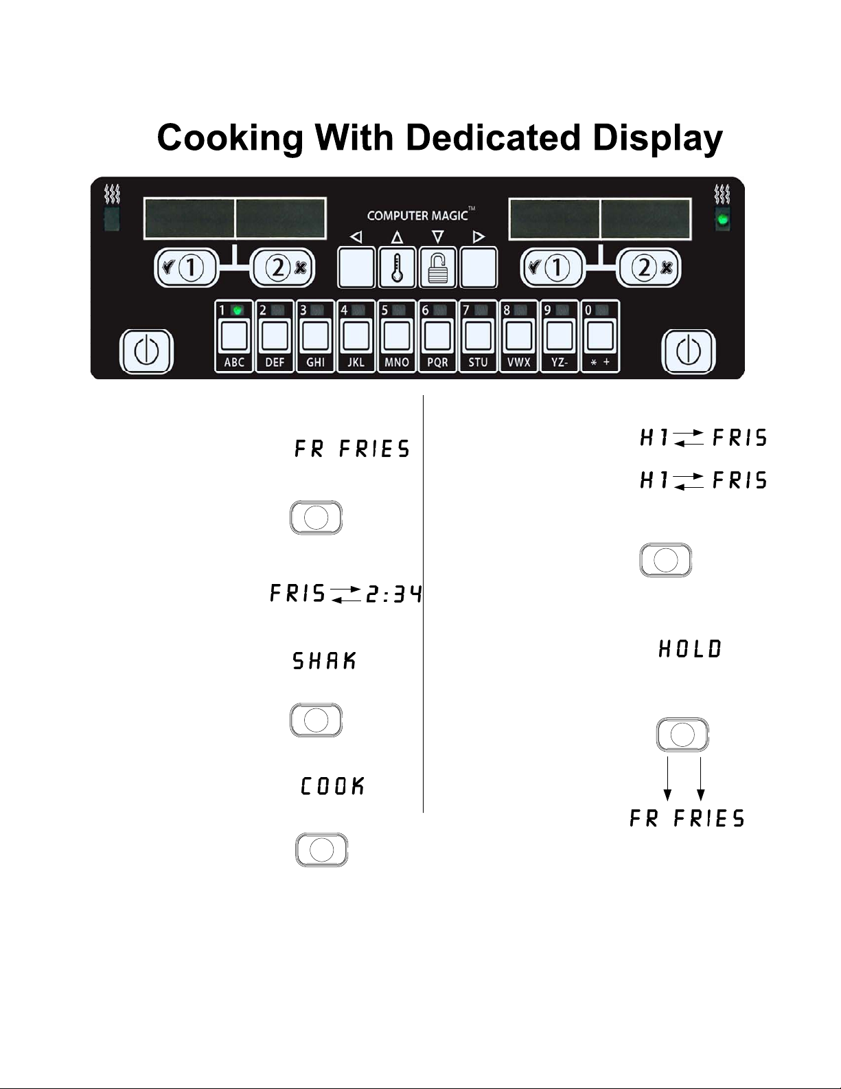
4.4 Cooking with Dedicated Display
FR FRIES FR FRIES
A menu item, such as
1
FR FRIES shows in
display
Press a cook channel
2
button to begin the
cook cycle.
Display alternates
3
between abbreviated
product name and
remaining cook time.
Shak is displayed when
4
it is time to shake the
fry basket.
Press cook channel
5
button to cancel alarm.
6
Cook is displayed
when the cook cycle
is complete.
H1 is displayed and
8
alternates with FRIS.
As the quality time
counts down.
1
1
Pressing the cook
9
channel button now
will launch a cook
cycle and end the
quality countdown.
Hold is displayed
10
when the quality time
has elapsed.
Pressing the cook
11
channel button
restores the display to
FR FRIES and the unit
is ready for cooking.
1
1
7
Press cook channel
button to cancel
alarm.
1
4-4
Page 28

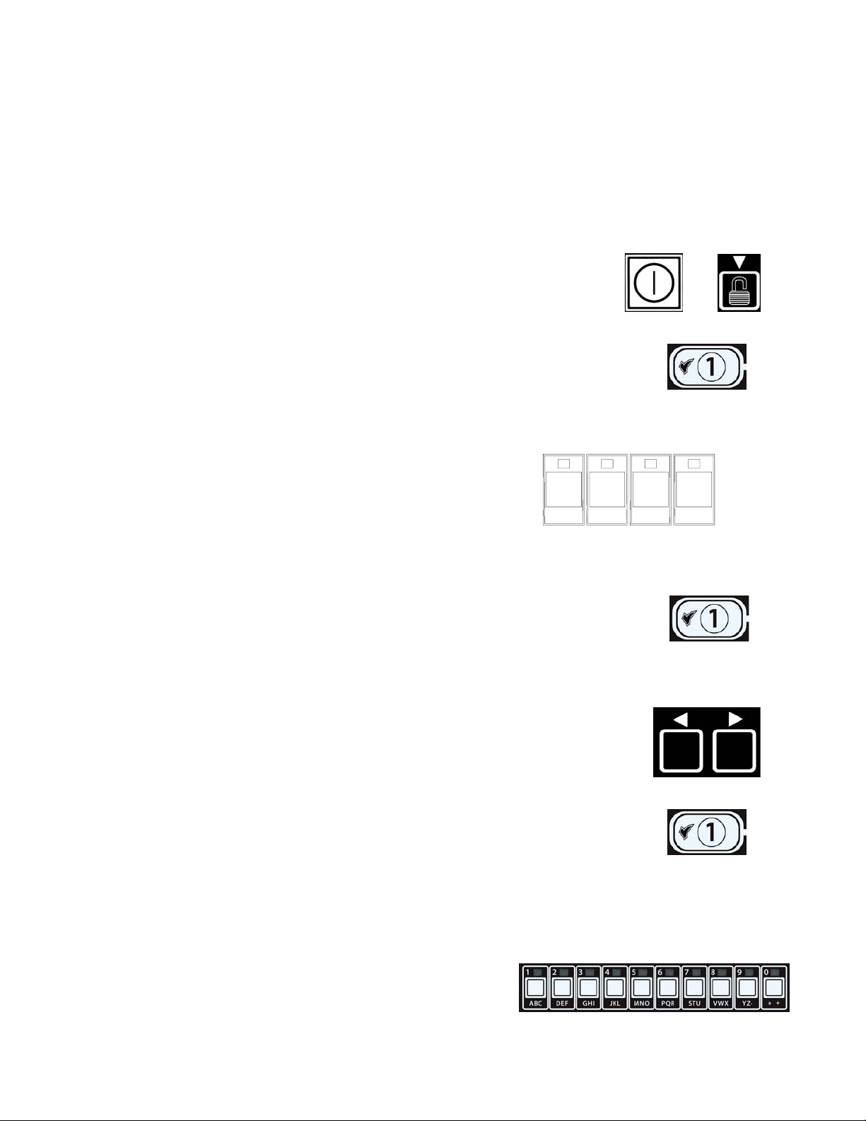
4.5 Changing from Breakfast Setup to Lunch
4-5
Page 29

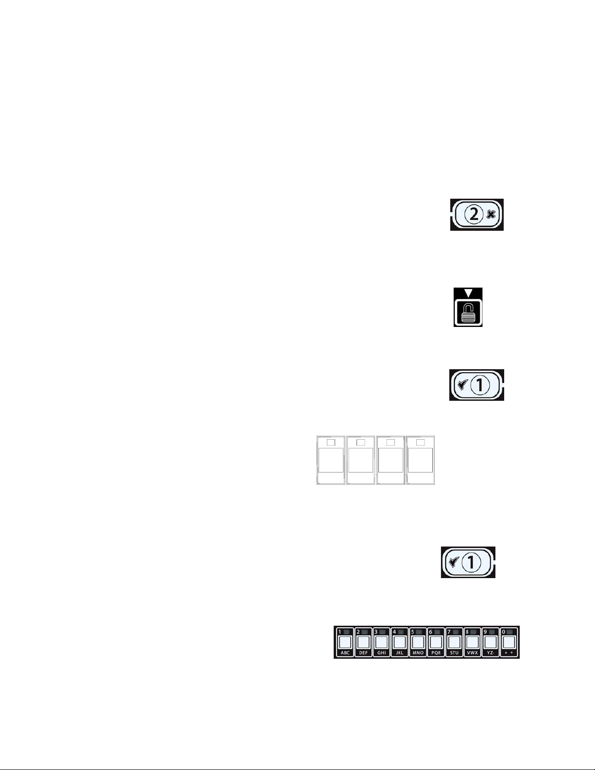
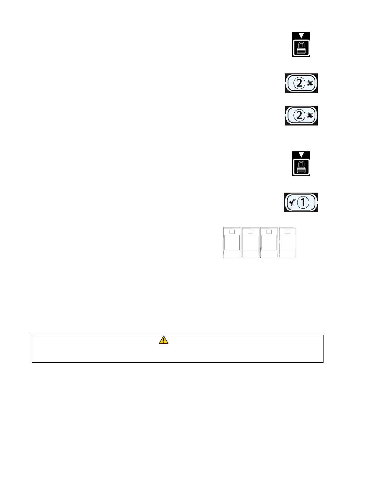
4.6 Changing from Lunch Setup to Breakfast
4-6
Page 30

4.7 CM7 Button Description and Functions
4.7.1 Navigation Buttons
The menu on the CM7 uses 34and tu buttons to
navigate the various menus and submenus (see Figure 1).
Figure 1
When programming, the left screen shows a menu or submenu item. The right screen is for data
entry. Data is entered with alpha-numeric characters, scrolling through lists or by toggling between
choices.
During programming, if a button is not pushed within one minute, the computer returns to operation
mode.
4.7.2 Temperature and Unlock Buttons
The TEMP button (see Figure 1), if pressed once while the fryer is on, displays current vat
temperature on both sides. If the TEMP button is pressed twice, it shows the setpoint temperatures
of the vats. If the fryer is off, the display shows the current versions of software. The UNLOCK
button (see Figure 1), if pressed once while the fryer is on, shows the recovery time for each vat
from the last test. Recovery displays the time required for the f ryer to raise the temperature of the oil
50°F (28°C) between 250°F (121°C) and 300°F (149°C). Maximum recovery time should not
exceed 1:40 for electric or 2:25 for gas. If the fryer is off, pressing the unlock button once allows
access to Program Mode; pressing twice allows access to Manager Mode and pressing three times
allows access to Tech Mode.
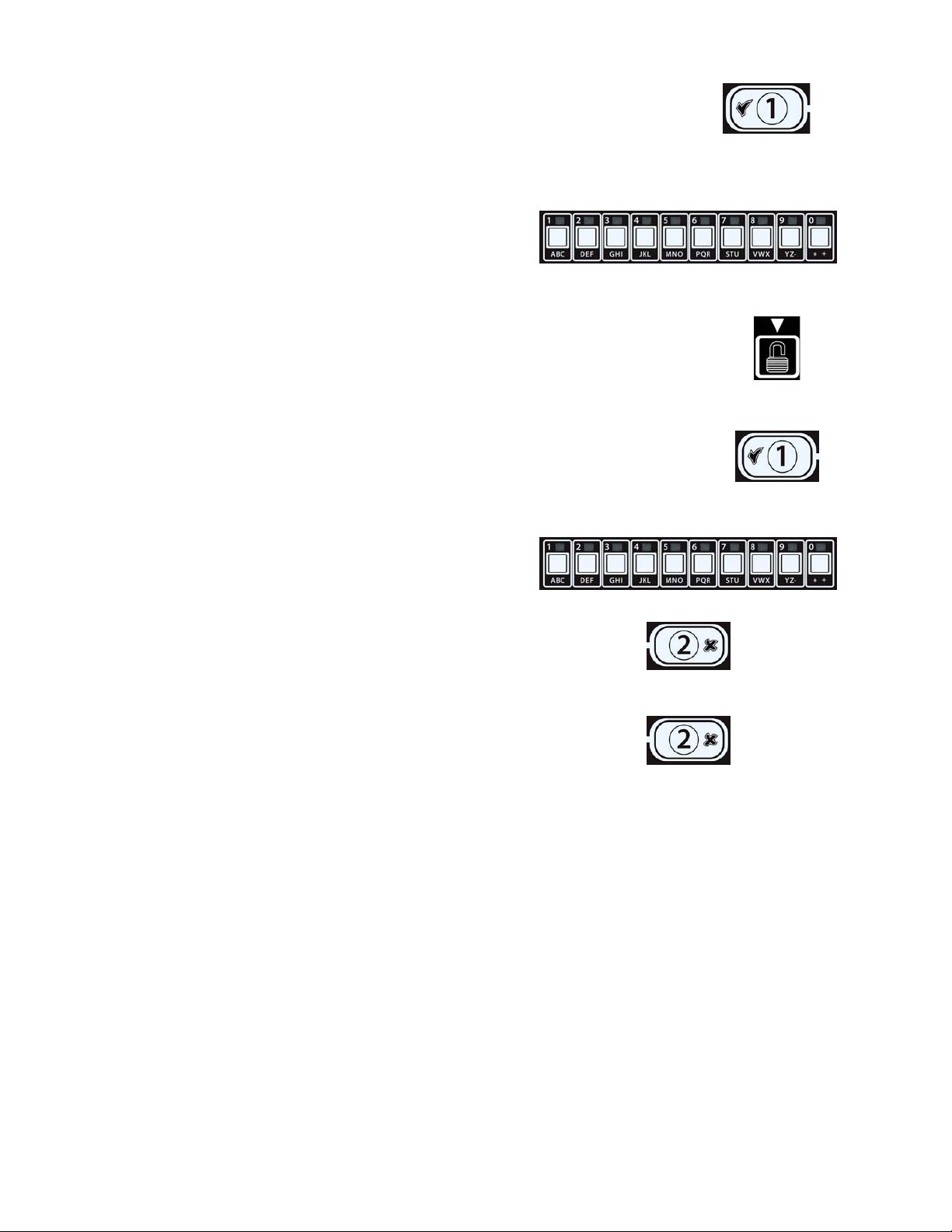
4.7.3 Cook Cycle and Selection Buttons
The 9 and 8 buttons are dual-function buttons shared
with the number 1 and 2 buttons. They are located directly
below the LED displays (see Figure 2). Use these buttons
to select or cancel functions. The 8 button is used to back
Figure 2
out of submenus.
4.7.4 Melt Cycle and Cooking Displays
Once the computer is switched on, it displays CYCL during melt cycle until the oil reaches 180°F
(82°C). The display changes to LOW TEMP until setpoint is reached. Once setpoint is reached,
the computer will display dashed lines or the product name
4-7
Page 31

4.8 CM7 Menu Summary Tree
Reflected below are the major programming sections in the CM7 and the order in which submenu
headings will be found under the sections in the Installation and Operation Manual.
Adding New Product Menu Items See section 4.10.2
Storing Product Menu Items in Product Buttons See section 4.10.3
Temperature Conversion from F° to C° See section 4.10.4
4-8
Page 32
4.9 Setup Mode Programming
The computer, upon initial power up or when accessed from Tech Mode, enters setup mode. These
parameters need to be set to allow the computers functions to operate correctly. The setup sets the
time, date, date format, language, fryer type, vat type, oil system type and the temperature format.
These settings should only be changed by a technician.
On initial power up the computer displays OFF
1. Press either soft power button (see Figure 3) or with the computer
OFF, enter Tech Mode by pressing the UNLOCK button three times
(see Figure 4).
2. The computer displays TECH if initially powering up the computer or
if entering setup through Tech Mode. Press the 9 (1) button to
continue (see Figure 5).
The computer displays CODE.
3. Enter 7378 (SERV) (see Figure 6).
7
3
The computer displays TECH MODE changing to
SETUP.
Figure 6
The computer displays FRYER SETUP changing to TIME FORMAT.
4. Press the 9 (1) button to continue (see Figure 7).
Computer displays time format with format on the right.
5. Use the 3and 4 buttons (see Figure 8) to toggle between 24hr and
12hr.
Figure 3 Figure 4
7
Figure 5
8
(7378)
Figure 7
Figure 8
6. With the desired selection displayed, press the 9 (1) button (see Figure
9).
Figure 9
The computer displays ENTER TIME on the left and hh:MM on the right.
Example: 7:30 AM is entered 0730 if using the 12 hour format. 2:30 is entered 1430 if using 24 hour
format.
7. Enter time in hours and minutes using the number
buttons 0-9 (see Figure 10).
Figure 10
4-9
Page 33

8. With the desired selection displayed, press the 9 (1) button (see Figure
11).
Figure 11
The computer displays ENTER TIME on the left and AM on the right if 12 hours system is
chosen.
9. Use the 3and 4 buttons (see Figure 12) to toggle between am and pm.
Figure 12
10. With the desired selection displayed, press the 9 (1) button (see Figure
13).
Figure 13
The computer displays DATE FORMAT on the left and US on the right.
11. Use the 3and 4 buttons (see Figure 14) to toggle between US and
interntl.
Figure 14
The computer displays enter date on the left and MM-DD-YY or DD-MM-YY on the
right.
Example:
US Format – Mar. 15, 2007 is entered as 031507.
International Format – 15 Mar. 2007 is entered as 150307)
12. Enter the date using the number buttons 0-9 (see
Figure 15).
Figure 15
13. With the desired selection displayed, press the 9 (1) button (see Figure
16).
Figure 16
The computer displays LANGUAGE on the left and ENGLISH on the right.
14. Use the 3and 4buttons to scroll through the language menu (see Figure
17).
Current languages supported by the CM7 are: English, French, French
Canadian, Spanish, Portuguese, German and Swedish.
Figure 17
15. With the desired selection displayed, press the 9 (1) button (see Figure
18).
Figure 18
The computer displays fryer type on the left and Elec on the right.
4-10
Page 34

16. Use the 3and 4buttons (see Figure 19) to toggle between elec and
gas.
Figure 19
17. With the desired selection displayed, press the 9 (1) button (see Figure
20).
Figure 20
The computer displays VAT type on the left and SPLIT on the right.
18. Use the 3and 4buttons (see Figure 21) to toggle between split and
full.
Figure 21
19. With the desired selection displayed, press the 9 (1) button (see Figure
22).
Figure 22
The computer displays Oil SYSTEM on the left and JIB on the right.
20. Use the 3and 4buttons (see Figure 23) to toggle between jib and
bulk.
Figure 23
NOTE: A JIB system uses a disposable JIB (Jug in a Box). A BULK system has large storage oil
tanks that are connected to the fryer.
21. With the desired selection displayed, press the 9 (1) button (see Figure
24).
Figure 24
The computer displays TEMPERATURE on the left and F on the right.
22. Use the 3and 4buttons (see Figure 25) to toggle between F and C
temperature scales.
NOTE: F is used for Fahrenheit, C is used for Celsius.
Figure 25
23. With the desired selection displayed, press the 9 (1) button (see Figure 26).
Figure 26
The computer displays FRYER Setup for three seconds then off.
4-11
Page 35
4.10 CM7 Common Tasks
Covered in this section are common tasks used in stores:
1. Escaping out of a menu or sub-menu.
2. Adding new product items.
3. Storing menu items in product buttons.
4. Temperature conversion from F to C.
4.10.1 Escape Menu Items
To escape from MENUS or SUB-MENUS, press the 8 (2) button (Figure
27).
4.10.2 Adding New Product Items to the Menu
To add a new product to the menu:
1. With the computer OFF, enter Program mode by pressing the
UNLOCK button once (see Figure 28).
The computer displays PROGRAM.
2. With the desired selection displayed, press the 9 (1) button (see Figure
29).
The computer displays ENTER Code and sounds an audible alert.
3. Enter 1650 (see Figure 30).
1
6
5
Figure 27
Figure 28
Figure 29
0
Figure 30
(1650)
The computer displays program MODE changing to SETPOINT TEMPERATURE.
4. Press the 9 (1) button to continue (see Figure 31).
Figure 31
Computer displays TEMP on the left and a temperature on the right.
5. Enter the desired cooking temperature using the
number buttons 0-9 (see Figure 32).
Figure 32
4-12
Page 36

6. With the desired temperature entered, press the ▼ button (see Figure
33) two times to lock in the setpoint and continue.
Figure 33
The computer displays Product selection.
7. With Product selection displayed, press the 9 (1) button
(see Figure 34).
Figure 34
Computer displays PRODUCT Selection changing to select product.
8. With Select Product displayed on the left and PROD 1
displayed on the right use the
through menu items until the right display displays the menu item to be
modified or the desired location for a new product.
4 button (see Figure 35) to advance
Figure 35
9. Press the 9 (1) button to select the product to modify (see Figure 36).
The computer displays modify alternating with yes no.
Figure 36
10. Press the 9 (1 yes) button (see Figure 37).
Figure 37
The left display displays NAME and the right display displays a product name (ex. PROD 1). The
right display shows a blinking cursor alternating with a blinking letter under the first character.
11. Using the number keys, enter the first letter of the new
product (see Figure 38). Press the key until the desired
letter appears.
Figure 38
12. Press the 4 button to advance the cursor to the next display space (see
Figure 39). Use the #0 key to insert a space. The 3button can be used to
move the cursor back.
Figure 39
For example, to enter “WINGS”, press the #8 key two times until W appears in the display. Then
use the 4 button to advance the cursor to the next display space. Press the #3 key until I appears.
Continue on until WINGS is spelled out on the display. Use no more than eight letters.
13. With the name entered, press the u button (see Figure 40) to save the
name and scroll to cook time.
Figure 40
14. With cook time displayed on the left and :00 or
a previously entered cook time displayed on the right,
use the number keys (see Figure 41) to enter the
product cook time in minutes and seconds (ex. 3:00 as
Figure 41
300).
4-13
Page 37

15. Press the u button (see Figure 42) to save the cook time and scroll to
the COOK ID.
Figure 42
16. A blinking P 1 is displayed on the right. Follow the instructions in step eleven to enter a fourletter name for the products which alternates with the cook time during a cook cycle.
17. Press the ubutton (see Figure 43) to save the cook ID abbreviation and scroll
to the SHAKE TIME, which is used to set the time in the cook cycle the
product should be shaken.
Figure 43
18. Use the number keys (see Figure 44) to enter the
elapsed time in minutes and seconds, before a shake is
required.
Figure 44
19. Press the ubutton (see Figure 45) to save shake time and scroll to HOLD
TIME. Hold time is the amount of time a product should be held before
being discarded.
Figure 45
20. Use the number keys (see Figure 46) to enter the time
in minutes and seconds the product should be held
before discarding. (ex. If the product requires
discarding after 10 minutes, enter 1000).
Figure 46
21. Press the ubutton (see Figure 47) to save hold time and scroll to FILT
AFTER. Filt after is the number of cook cycles before a filter prompt.
Figure 47
22. Use the number keys (see Figure 48) to enter the
number of cook cycles before the fryer prompts for
filtration. (ex. If the product requires filtration after
every six cook cycles, enter 6).
Figure 48
NOTE: Setting the FILT AFTER to “0” will disable
filtration prompts.
23. Press the ubutton (see Figure 49) to save FILT AFTER and scroll to
SENSITIVITY.
Figure 49
Sensitivity is a built-in feature, which adjusts cooking time to compensate for the drop in frypot
temperature when a product enters the oil. Different products vary in density, batch size, and
temperature. Food products will also vary in cook time. A proper sensitivity setting will assure a
high-quality product. Setting zero is the least sensitive and setting nine is the most sensitive. The
default setting is 0. Some menu items may need an adjustment, depending on their cooking
characteristics. A chart is provided on page 4-21 to assist in choosing a sensitivity setting. It is
meant as a guide only and the settings may be changed to suit different needs. Use caution when
changing sensitivity, as it could have an adverse affect on the products cooking cycles.
4-14
Page 38

24. With sensitivity displayed on the left and 0
displayed on the right, use the number keys (see
Figure 49) to enter a number between 0-9.
Figure 49
25. Press the ubutton (see Figure 50) to save sensitivity and scroll to assign btn.
Figure 50
26. Press and hold for three seconds an unassigned button between 1-0 to
assign the product. The LED in the chosen product button will illuminate
(see Figure 51). To unassign a product from a button, press and hold the
button assigned to that product for three seconds. The LED no longer
illuminates.
Figure 51
27. Press the ubutton (see Figure 52) to save the assigned button.
The computer displays name on the left with the product (ex. WINGS) on the right.
Figure 52
* Note: If additional programming, to add other products, is necessary
press the 8 (2) button (see Figure 53) once and then the 4 button
(see Figure 54) and return to step 8.
Figure 53 Figure 54
28. If no further programming is necessary, press the 8 (2) button three times (see
Figure 55). The computer displays OFF.
Figure 55
4.10.3 Storing Menu Items in Product Buttons
This function is used to store individual menu items in product buttons for one or two button
cooking.
To store menu items to a specific button:
1. Perform steps 1-10 on pages 4-12 thru 4-13.
2. The computer displays NAME on the left and the selected product (ex. wings) on the right.
3. Press the t button (see Figure 56) to scroll to the ASSIGN BTN option
used to assign a menu item to a specific product button.
4. The computer displays assign btn on the left and wings on the
right.
5. Press and hold for three seconds a button between 1-0 to assign the
product. The LED in the chosen product button will illuminate (see
Figure 57). To unassign a product from a button, press and hold the
button assigned to that product for three seconds. The LED no longer
illuminates.
Figure 56
Figure 57
4-15
Page 39
6. Once the button is assigned, press the u button (see Figure 58) to save the
assigned button.
The computer displays name on the left with the product (ex. WINGS) on the
right.
7. If no further programming is necessary, press the 8 (2) button (see Figure 59)
twice to return to setpoint temperature prompt.
8. Press the 8 (2) button again to exit and to return to OFF (see Figure 60).
4.10.4 Temperature conversion from F° to C°.
1. With the computer OFF, enter Tech mode by pressing the UNLOCK button
three times (see Figure 61).
The computer displays TECH
2. With the desired selection displayed, press the 9 (1) button (see Figure 62).
The computer displays Code and sounds an audible alert.
3. Enter 1658 (see Figure 63).
Switch computer on to see if temperature scale changed. If
not, repeat steps 1-3.
Figure 63
1
6
5
Figure 58
Figure 59
Figure 60
Figure 61
Figure 62
8
(1658)
4.11 Boil-Out Mode
Before the fryer is first used, it should be boiled out to ensure that residue from the manufacturing
process has been eliminated. Also, after the fryer has been in use for a period of time, a hard film of
caramelized oil will form on the inside of the frypot. This deposit must be periodically removed to
maintain your fryer’s efficiency.
DANGER
Allow oil to cool to 100ºF (38ºC) or lower before draining to an appropriate METAL
container for disposal.
1. Drain the frypot in accordance with Section 5.1 (page 5-1), but do not refill with cooking oil.
2. After draining the frypot, clean all food particles and residual oil from the frypot and filter pan (if
so equipped). BE CAREFUL, this material may still cause severe burns if it comes in contact
with bare skin.
3. Close the drain valve securely and fill the frypot with a solution of automatic dishwasher
detergent (or commercially available boil-out solution) and cold water to the bottom OIL-
LEVEL line.
4-16
Page 40

DANGER
Never leave the fryer unattended during the boil-out process. If the boil-out solution
boils over, press and hold the 8 (2) button for five seconds, then release the button
to cancel boil-out immediately and let the solution cool for a few minutes before
resuming the process.
5. With the computer OFF, press the UNLOCK button once (see Figure 64).
The computer displays PROGRAM.
Figure 64
6. Press the 9 (1) button (see Figure 65).
The computer displays ENTER Code and sounds an audible alert.
7. Enter 1650 (see Figure 66).
1
Figure 65
6
5
0
The computer displays program MODE changing to
SETPOINT TEMPERATURE.
Figure 66
(1650)
8. Press the u button to scroll to BOIL-OUT MODE (see Figure 67).
Figure 67
9. Press the 9 (1) button to continue (see Figure 68).
The computer displays boil out, alternating with yes no.
Figure 68
10. Press the 9 (1 yes) button to continue the boil out process (see Figure 69).
Figure 69
CAUTION
Ensure the frypot is filled with a mixture of cold water and detergent before starting
boil-out.
The computer displays strt boil, alternating with yes no.
11. Press the 9 (1 yes) button to start boil-out (see Figure 70).
The computer displays boilOUT on both sides. The fryer heats to 195°F (91°C).
Figure 70
12. Let the solution simmer for one hour. Do not allow the water level to drop below the bottom oil-
level line in the frypot during the boil-out operation.
13. Press and hold the 8 (2) button for five seconds. Release the button to cancel boil-out when it is
finished. The fryer turns OFF. Drain the solution and close the drain valve.
4-17
Page 41
14. Allow the solution to cool to 100°F (38°C), then drain into a METAL stockpot or similar
METAL container. When draining is finished, close the fryer drain valve securely.
DANGER
Allow solution to cool to 100°F (38°C) before draining into an appropriate METAL
container for disposal.
WARNING
Do not drain boil-out solution into a shortening disposal unit (SDU), a built-in
filtration unit, or a portable filter unit. These units are not intended for this purpose,
and will be damaged by the solution.
15. Add two gallons (7.6 liters) of water. Drain out the solution and clean the frypot(s) thoroughly.
16. Refill the frypot(s) with clean water. Rinse the frypot(s) twice, drain and dry with a clean towel.
Thoroughly remove all water from the frypot and elements before refilling the frypot with oil.
DANGER
Ensure that the frypot is completely free of water before filling with oil. Failure to do
so will cause splattering of hot liquid when the oil is heated to cooking temperature.
4.11.1 Clean Filter Pan, Detachable Parts and Accessories
As with the frypot, a deposit of carbonized oil will accumulate on the filter pan and detachable parts
and accessories such as baskets, sediment trays, or fish plates.
Wipe the filter pan and all detachable parts and accessories with a clean cloth dampened with a
detergent solution (or the parts can be run through a dishwasher). Rinse and thoroughly dry each
part. DO NOT use steel wool or abrasive pads to clean these parts. The scratches that result from
such scrubbing make subsequent cleanings more difficult.
WARNING
Use a commercial-grade cleaner formulated to effectively clean and sanitize
food-contact surfaces. Read the directions for use and precautionary statements
before use. Particular attention must be paid to the concentration of cleaner and
the length of time the cleaner remains on the food-contact surfaces.
4-18
Page 42

4.12 Manager Mode
1. With the computer OFF, press the UNLOCK button
twice (see Figure 71).
The computer displays MANAGER and sounds an
Figure 71
audible alert.
2. Press the 9 (1) button (see Figure 72).
The computer displays ENTER Code and sounds an audible alert.
3. Enter 4321 (see Figure 73).
4
3
2
The computer displays MANAGER MODE changing
to E-LOG.
Figure 73
The E-LOG mode is used to view the ten most recent error codes encountered on the fryer. These
codes are displayed from 1-10 with the most recent displayed first. The time, date and error code are
displayed.
4. Press the 9 (1 ) button to accept selection (see Figure 81).
Figure 72
1
(4321)
Figure 74
5. Use the t and ubuttons to scroll through the ten most recent error codes.
If no errors exist, the computer displays NO ERRORS. Errors are displayed by error code, time
and date.
Error Codes:
E01 - Right Remove Discard
E02 - Left Remove Discard
E03 - Probe Failure - Call Technician
E04 - Hi Limit 2 - Call Technician
E05 - Hot Hi 1 - Call Technician
E06 - Ignition Failure - Call Technician
6. Press the 8 (2) button (see Figure 75) once.
The computer displays ALERT TONE.
Figure 75
The alert tone mode allows a manager to adjust the volume to nine levels and the tone is adjustable
to three frequencies. One of three audio frequencies may be chosen to distinguish fryers in kitchens
with multiple fryers.
7. Press the 9 (1) button (see Figure 76).
Computer displays volume 1-9.
Figure 76
4-19
Page 43
8. Press the 9 (1) button (see Figure 77).
The computer displays volume 1-9 on the left and 1 on the right.
9. Use the number keys to set volume level (see Figure
78). Select from nine levels of volume with 0 being
off, 1 the softest and 9 the loudest.
Figure 78
10. Press the u UNLOCK button to accept the selection and to scroll to tone
1-3 (see Figure 79).
Computer displays tone 1-3.
11. Press the 9 (1) button (see Figure 80).
The computer displays tone 1-3 on the left and 1 on the right.
12. Use the number keys, to set the tone frequency (see
Figure 81). Select from three different frequencies.
Figure 81
13. Press the 8 (2) button again (see Figure 82) to return
to MANAGER MODE changing to E-LOG.
Figure 82
14. Press the 8 (2) button again (see Figure 83) to quit
and to return to OFF.
Figure 83
Figure 77
Figure 79
Figure 80
4-20
Page 44

4.13 SENSITIVITY SETTINGS CHART
Sensitivity Settings for Various Products
Product 350° F/176° C Sensitivity Setting
Chicken
chicken fillet, 1 ¼ oz. 3:25 5
chicken fillet (frozen), 4 oz. 4:20 5
chicken patty (frozen), 5 oz. 6:15 5
frozen chicken 5
fresh chicken, 9 pieces 5
Potatoes
steak fries 3:43 5
regular fries, ½-inch 3:16 5
shoestrings, ¼-inch 1:50 5
shoestrings, 3/8-inch 2:40 5
tater tots 2:05 5
hash browns 2:05 5
farm fries 1:14 5
Seafood
crab cakes 4:00 3
clam cakes 4:00 3
large scallops 3:25 3
small scallops 1:10 3
shrimp (35 to a lb.) 2:15 3
shrimp (40 to 75 to a lb.) 1:45 3
shrimp (75 to 100 to a lb.) 1:10 3
cod, 2 ½ oz. 3:25 7
flounder fillet, 7 oz. 4:35 3
flounder, whole, 10-12 oz. 6:25 3
cod fillet, 3 ½ oz. 4:35 7
perch, 5 oz. 4:30 3
haddock, 7 oz. 6:25 7
clams 2:00 3
oysters 1:10 4
strip clams (fresh) 0:35 4
strip clams (frozen) 0:45 4
Vegetables
okra 4:30 4
eggplant 4:00 4
zucchini 3:00 4
mushrooms 3:45 4
onion rings (frozen) 3:00 4
cauliflower 1:45 4
Other
corn dogs 4
chicken fried steak patty 5:00 5
Note: This chart is provided to assist in choosing a sensitivity setting. It is meant as a guide only and the
settings may be changed to suit different needs.
4-21
Page 45

PROTECTOR® SERIES GAS FRYERS
CHAPTER 5: FILTRATION INSTRUCTIONS
WARNING
The on-site supervisor is responsible for ensuring that operators are made aware of
the inherent hazards of operating a hot oil filtering system, particularly the aspects
of oil filtration, draining and cleaning procedures.
5.1 Draining and Manual Filtering
DANGER
Draining and filtering of cooking oil must be accomplished with care to avoid the
possibility of a serious burn caused by careless handling. The oil to be filtered is at
or near 350°F (177°C). Ensure all hoses are connected properly and drain handles
are in their proper position before operating any switches or valves. Wear all
appropriate safety equipment when draining and filtering oil.
DANGER
Allow oil to cool to 100°F (38°C) before draining into an appropriate container for
disposal.
DANGER
Do not drain more than one frypot at a time into the built-in filtration unit to avoid
overflow and spillage of hot oil that may cause severe burns, slipping and falling.
DANGER
When draining oil into a disposal unit or portable filter unit, do not fill above the
maximum fill line located on the container.
Oil must be drained into the filter pan, SDU or another suitable METAL container. (For safe,
convenient draining and disposal of used oil or shortening, Frymaster recommends using the
Frymaster Shortening Disposal Unit (SDU). The SDU is available through your local distributor.)
1. Turn the fryer power switch to the OFF position.
2. Position a METAL container with a sealable cover under the drainpipe. The METAL
container must be able to withstand the heat of the oil and hold hot liquids. If you intend to reuse
the oil or shortening, Frymaster recommends that a Frymaster
be used when a filter machine is not available. If you are using a Frymaster filter cone holder, be
sure that the cone holder rests securely on the metal container.
3. Open the drain valve slowly to avoid splattering. If the drain valve becomes clogged with food
particles, use the Fryer’s Friend (poker-like tool) to clear the blockage.
filter cone holder and filter cone
5-1
Page 46

DANGER
NEVER attempt to clear a clogged drain valve from the front of the valve! Hot oil will
rush out creating the potential for severe burns.
DANGER
DO NOT hammer on the drain valve with the cleanout rod or other objects. Damage
to the ball inside will result in leaks and will void the Frymaster warranty.
4. After draining the oil, clean all food particles and residual oil from the frypot. BE CAREFUL,
this material may still cause severe burns if it comes in contact with bare skin.
5. Close the drain valve securely and fill the frypot with clean, filtered or fresh cooking oil to the
bottom OIL-LEVEL line.
5.2 Preparing the Built-In Filtration System for Use
The FootPrint Pro filtration system allows the oil in one frypot to be safely and efficiently filtered
while the other frypots in a battery remain in operation. The FootPrint Pro filtration system is
available in three different configurations:
• Filter Paper – includes crumb tray, large hold-down ring, and metal filter screen.
• Filter Pad – includes crumb tray, small hold-down ring, and metal filter screen.
Section 4.2.1 covers preparation of the Filter Paper and Filter Pad configurations for use. Refer to
Section 4.2.2 for instructions on preparing the Magnasol Filter configuration for use. Operation of
all three configurations is the same and is covered in section 4.3. Disassembly and reassembly of the
Magnasol filter is covered in section 4.4.
• Magnasol Filter – includes crumb tray and Magnasol filter assembly.
5-2
Page 47

5.2.1 Preparation for Use with Filter Paper or Filter Pad
1. Pull the filter pan out from the cabinet
and remove the crumb tray, hold-down
ring, filter paper and filter screen. (See
Figure 1) Clean all components with a
solution of detergent and hot water, then
dry thoroughly.
The pan cover must not be removed
except for cleaning, interior access, or to
allow a shortening disposal unit (SDU)
to be positioned under the drain. If using
an SDU built before January 2004 see
instructions on page 5-8.
2. Inspect the filter pan connection fitting
to ensure that both O-rings are in good
condition. (See Figure 2)
3. Then in reverse order, place the metal
filter screen in the center of the bottom
of the pan, then lay a sheet of filter paper
on top of the screen, overlapping on all
sides. (See Figure 1) If using a filter
pad, ensure the rough side of the pad is
up and lay the pad over the screen,
making sure that the pad is in between
Inspect the filter
connection fitting
O-rings.
the embossed ridges of the filter pan.
4. Position the hold-down ring over the
Figure 2
filter paper and lower the ring into the
pan, allowing the paper to rest on the
sides of the filter pan. (See Figure 3)
Figure 1
Figure 3
5-3
Page 48

5. When the hold-down ring is in position,
if using filter paper, sprinkle one packet
of filter powder evenly over the paper.
(See Figure 4)
If using a filter pad
, position the hold
down ring on top of the pad. DO NOT
use filter powder with the pad.
Figure 4
6. Replace the crumb tray in the filter pan, then push the filter pan back into the fryer, positioning it
under the drain.
5.2.2 Preparation for Use with the Magnasol Filter Assembly
1. Pull the filter pan out from the cabinet
and remove the crumb tray and
Magnasol filter assembly (See Figure 5).
Clean as directed in section 5.4.
The pan cover must not be removed
except for cleaning, interior access, or to
allow a shortening disposal unit (SDU)
to be positioned under the drain.
NOTE: Refer to Section 5.4 for
instructions on how to disassemble and
reassemble the Magnasol filter screen
Figure 5
assembly.
2. Inspect the fitting on the bottom of the
Magnasol filter assembly to ensure that
the O-ring is present and in good
condition. (See Figure 6)
Inspect the filter
screen O-ring.
3. Inspect the filter pan connection fitting
to ensure that both O-rings are present
Figure 6
and in good condition. (See Figure 7)
5-4
Inspect the filter
connection fitting
O-rings.
Figure 7
Page 49

4. Replace the Magnasol filter assembly in the filter pan, ensuring that the fitting on the bottom of
the assembly is securely seated in the port in the bottom of the pan. Sprinkle one packet of the
Magnasol XL filter powder evenly over the screen.
5. Replace the crumb tray, then push the filter pan back into the fryer, positioning it all the way to
the back of the cabinet.
5.3 Operation of the Filter
After a preset amount of cook cycles the computer will automatically display FLTR NOW
alternating with YES NO.
1. Press the 9 (1) button to continue (see Figure 8).
The computer displays CNFM FLTR alternating with YES NO.
Figure 8
2. Press the 9 (1) button to continue (see Figure 9).
Figure 9
DANGER
Draining and filtering of cooking oil must be accomplished with care to avoid the
possibility of a serious burn caused by careless handling. The oil to be filtered is at
or near 350°F (177°C). Ensure drain handles are in their proper position before
operating any switches or valves. Wear all appropriate safety equipment when
draining and filtering cooking oil.
DANGER
NEVER attempt to drain cooking oil from the fryer with the burners lit! Doing so will
cause irreparable damage to the frypot and may cause a flash fire. Doing so will also
void the Frymaster warranty.
3. Ensure that the filter is prepared. See Sec.
5.2.
4. Make sure the oil is at operating
temperature.
5. Drain the frypot into the filter pan by
rotating the drain valve handle 90º (see
Open drain valve by
rotating 90º.
Figure 10). If necessary, use the Fryer's
Friend clean-out rod to clear the drain
from inside the frypot.
Figure 10
DANGER
Do not drain more than one frypot at a time into the built-in filtration unit to avoid
overflow and spillage of hot oil that may cause severe burns, slipping and falling.
5-5
Page 50
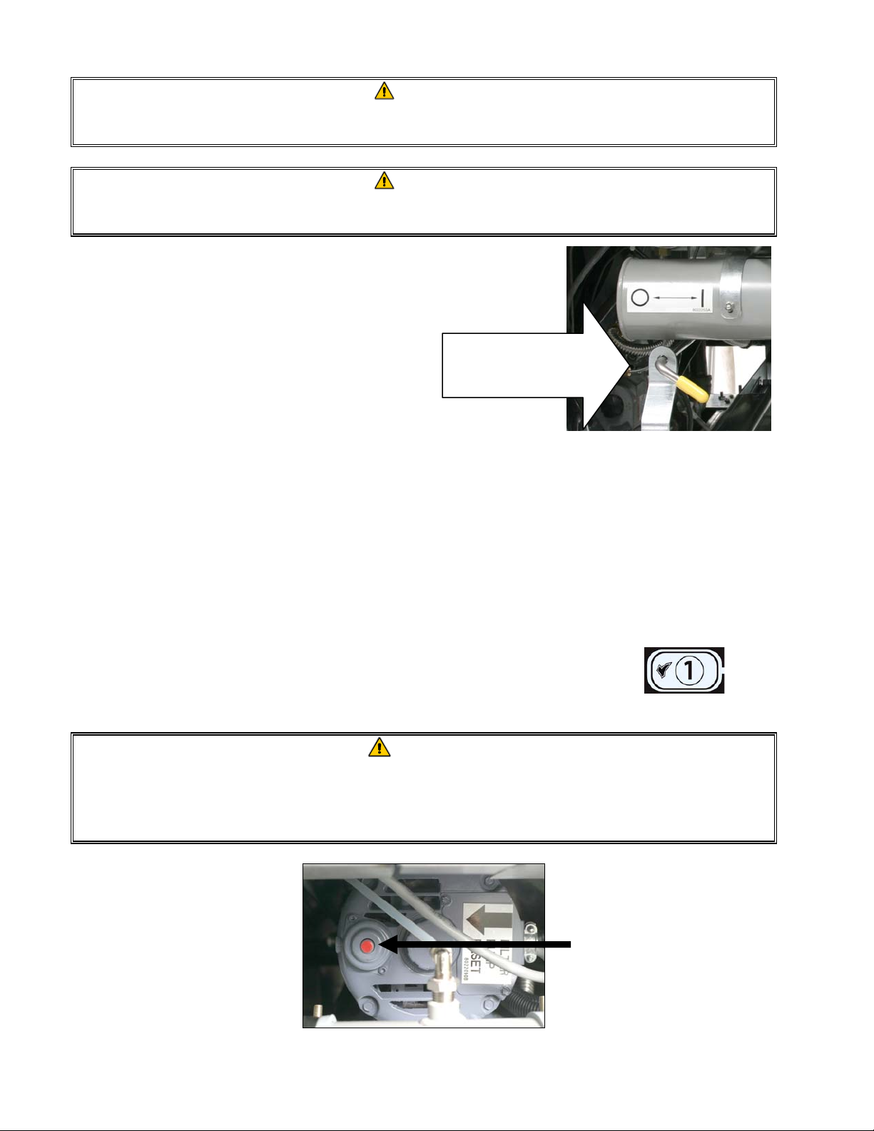
DANGER
NEVER attempt to clear a clogged drain valve from the front of the valve! Hot oil will
rush out creating the potential for severe burns.
DANGER
DO NOT hammer on the drain valve with the cleanout rod or other objects. Damage
to the ball inside will result in leaks and will void the Frymaster warranty.
6. After the oil has drained from the frypot,
rotate the filter handle towards the “I” to
start the pump and begin the filtering
process. There may be a slight delay
before the pump activates (see Figure
11).
Pull filter handle
forward to activate
pump.
Figure 11
7. The filter pump draws the oil through the filter medium and circulates it back up to and through
the frypot during a 5-minute process called polishing. Polishing cleans the oil by trapping solid
particles in the filter medium.
8. After the oil is filtered (about 5 minutes), close the drain valve and allow the fryer to refill. Let
the filter pump run 10 to 12 seconds after the oil begins to bubble. Turn the filter off.
The computer displays FILTER DONE alternating with YES NO.
9. Press the 9 (1) button when filtration is finished (see Figure 12).
The computer displays OFF.
Figure 12
WARNING
The filter pump is equipped with a manual reset switch in case the filter motor
overheats or an electrical fault occurs. If this switch trips, turn off power to the filter
system and allow the pump motor to cool 20 minutes before attempting to reset the
switch (see photo below).
Filter Pump Reset Switch
5-6
Page 51

WARNING
Use caution and wear appropriate safety equipment when resetting the filter pump
reset switch. Resetting the switch must be accomplished with care to avoid the
possibility of a serious burn caused by careless maneuvering around a drain tube
and around a frypot.
10. Ensure the drain valve is fully closed. (If the drain valve is not fully closed, the fryer will not
operate.) Turn the fryer ON and allow the cooking oil to reach setpoint.
DANGER
The crumb tray in fryers equipped with a filter system must be emptied into a
fireproof container at the end of frying operations each day. Some food particles can
spontaneously combust if left soaking in certain shortening material.
WARNING
Do not bang fry baskets or other utensils on the fryer’s joiner strip. The strip is
present to seal the joint between the fry vessels. Banging fry baskets on the strip to
dislodge shortening will distort the strip, adversely affecting its fit. It is designed for
a tight fit and should only be removed for cleaning.
5.4 Disassembly and Reassembly of the Magnasol Filter
Dissassembly
1. Grasp the frame with your thumbs on the handles at the corner of the assembly and pull outward
in opposite directions to separate the frame at the corner. Continue to open the frame (it will
pivot at the opposite corner) until the outer screens and grid can be removed from the frame.
Step 2 - Separate
the outer screens
and grid.
2. Separate the outer screens and grid.
5-7
Step 1 - Grasp frame with
thumbs on these handles and
pull frame appart at corner.
Page 52

Cleaning
1. Clean the two frame pieces, outer screens, and grid using a good quality degreaser and hot water
from a spray nozzle. The groove in the seal frame pieces can be cleaned with the edge of a
Scotch-Brite™ or similar cleaning pad.
2. At each scheduled boil-out, disassemble the leaf filter assembly and place in the frypot being
boiled out. Follow the boil-out procedure in Section 4.11 page 4-16 of this manual.
3. Allow all filter assembly components to air dry or thoroughly dry with clean towels before
reassembling.
Reassembly
1. Place the two outer screens together and align their edges (see illustration below).
2. Insert the screens into one of the frame halves (it doesn’t matter which one). Ensure that the
fitting in the bottom screen is on the opposite side of the frame from the handle.
3. Slip the grid between the screens, ensuring that the grid is centered between the edges of the
screens.
4. Connect the other half of the frame at the corner opposite the handles and pivot the frame onto
the free edges of the screen.
Steps 1 and 2 - Stack outer screens
and insert edges into frame.
Step 3 - Insert grid between screens
after screens have been positioned in
frame.
Handle
Step 4 - Connect corner then pivot
frame over free edges of screens.
5-8
Page 53

5.5 Draining and Disposing of Waste Oil
When cooking oil is exhausted, drain the oil into an appropriate METAL container for transport to
the disposal container. Frymaster recommends the use of the Frymaster Shortening Disposal Unit
(SDU). NOTE: If using an SDU built before January 2004 the filter pan cover must be removed to
allow the unit to be positioned beneath the drain. To remove the lid, lift up on the front edge and pull
it straight out of the cabinet. Refer to the documentation furnished with your disposal unit for
specific operating instructions. If a shortening disposal unit is not available, allow the oil to cool to
100°F (38°C), then drain the oil into a METAL stockpot or similar METAL container. When
draining is finished, close the fryer drain valve securely.
DANGER
Allow oil to cool to 100°F (38°C) before draining into an appropriate METAL
container for disposal.
DANGER
When draining oil into a disposal unit, do not fill above the maximum fill line located
on the container.
5.6 Using the “Optional” Oil Disposal
If the fryer is fitted with the optional oil disposal, ensure the filter
pan is clean and ready for filtering. DO NOT discharge oil through
a dirty or incomplete filter pan.
1. Ensure the oil is at operating temperature.
2. Turn the fryer off. Wear protective clothing and use caution. Hot oil can cause
serious injury.
3. Open the drain valve of the frypot with oil to be discarded. Drain only one
frypot at a time.
4. With the frypot drained and the oil to be discarded in the filter pan, close the
drain valve. Ensure all other drain valves and oil-return valves are closed.
5. Ensure the oil disposal reservoir is not full and the fryer is properly connected
to the oil disposal system.
6. Discharge the oil by engaging the discharge valve handle. The filter pump will
come on and the oil will be pumped from the filter pan. Turn the pump off by
disengaging the discharge valve handle when the filter pan empties. Repeat
steps 1-6 if necessary to discharge the oil from other frypots. DO NOT
discharge water or other liquids through the filter system.
Refill the fryer with fresh oil.
7.
5-9
Page 54

PROTECTOR® SERIES GAS FRYERS
CHAPTER 6: PREVENTIVE MAINTENANCE
6.1 FRYER PREVENTATIVE MAINTENANCE CHECKS AND SERVICE
DANGER
The crumb tray in fryers equipped with a filter system must be emptied into a fireproof container at the end of frying operations each day. Some food particles can
spontaneously combust if left soaking in certain shortening material.
DANGER
Never attempt to clean fryer during the cooking process or when the frypot is filled
with hot oil. If water comes in contact with oil heated to cooking temperature, it can
cause the oil to splatter and severely burn nearby personnel.
WARNING
Use a commercial-grade cleaner formulated to effectively clean and sanitize
food-contact surfaces. Read the directions for use and precautionary statements before use. Particular attention must be paid to the concentration of cleaner and the
length of time the cleaner remains on the food-contact surfaces.
6.2 DAILY CHECKS AND SERVICE
6.2.1 Inspect Fryer and Accessories for Damage
Look for loose or frayed wires and cords, leaks, foreign material in frypot or inside cabinet, and any
other indications that the fryer and accessories are not ready and safe for operation.
6.2.2 Clean Fryer Cabinet Inside and Out
Clean inside the fryer cabinet with dry, clean cloth. Wipe all accessible metal surfaces and components to remove accumulations of oil and dust.
Clean the outside of the fryer cabinet with a clean, damp cloth soaked with dishwashing detergent,
removing oil, dust, and lint from the fryer cabinet.
6.2.3 Clean the Built-in Filtration System Daily
WARNING
Never operate the filter system without oil in the system.
WARNING
Never use the filter pan to transport old oil to the disposal area.
WARNING
Never drain water into the filter pan. Water will damage the filter pump.
6-1
Page 55
There are no periodic preventive maintenance checks and services required for your FootPrint Pro
Filtration System other than daily cleaning of the filter pan with a solution of hot water and
detergent.
If you notice that the system is pumping slowly or not at all, verify that the filter pan screen is on the
bottom of the filter pan, with the paper on top of the screen. (If the unit is equipped with a Magnasol
filter screen rather than with the standard screen and paper system, verify that the O-ring on the
bottom fitting of the screen in present and in good condition.) Verify that the two O-ring(s) on the
fitting at the right front of the filter pan are present and in good condition.
6.3 WEEKLY CHECKS AND SERVICE
6.3.1 Drain and Clean Frypot
DANGER
Never operate the appliance with an empty frypot. The frypot must be filled with
water or oil before lighting the burners. Failure to do so will damage the frypot and
may cause a fire.
6.3.2 Boiling Out the Frypot
After the fryer has been in use for a period of time, a hard film of caramelized oil will form on the
inside of the frypot. This deposit must be periodically removed to maintain your fryer’s efficiency.
See section 4.11 page 4-16 for instructions on boiling out the frypot.
6.4 MONTHLY CHECKS AND SERVICE
6.4.1 Check Computer Magic 7 Set Point Accuracy
(This check applies only to units equipped with Computer Magic 7 Controllers.)
1. Insert a good-grade thermometer or pyrometer probe into the oil, with the end touching the fryer
temperature-sensing probe.
2. When the computer display shows a series of four dashes “----” with no dot between the first and
second dashes (indicating that the frypot contents are within the cooking range), press the
switch once to display the temperature of the cooking oil as sensed by the temperature probe.
3. Press the switch twice to display the set point.
4. Note the temperature on the thermometer or pyrometer. All three readings should be within
± 5ºF (2ºC) of each other. If not, contact a Factory Authorized Service Center for assistance.
6-2
Page 56

6.5 QUARTERLY CHECKS AND SERVICE
6.5.1 Clean Combustion Air Blower Assembly
1. Disconnect the blower wiring harness and remove the four blower mounting nuts (see Figure 1
below).
Wiring connection
Blower
assembly
mounting nuts
Figure 1
2. Remove the three fasteners that secure the blower motor assembly to the blower housing, and
separate the two components (see Figure 2).
Remove these fasteners.
Figure 2
6-3
Page 57

3. Wrap the motor with plastic wrap to prevent water from entering it. Spray degreaser or
detergent on the blower wheel and the blower housing. Allow it to soak for five minutes. Rinse
the wheel and housing with hot tap water, then dry with a clean cloth (see Figure 3).
Wrap the mot o r and wires
with plastic wrap or a
plastic bag.
Blower Housing
Blower Wheel
Figure 3
4. Remove the plastic wrap from the blower motor assembly. Reassemble the blower motor
assembly and blower housing. Reinstall the blower assembly in the fryer.
5. Reinstall the blower shield or shield assembly.
6. Light the fryer in accordance with the procedure described in Chapter 3, Section 3.2.2.
7. After the burners have been lit for at least 90 seconds, observe the flames through the burner
viewing ports located on each side of the combustion air blower (see Figure 4).
Left Viewing
Port is Behind
Motor
(NOTE: Blower
shield omitted
for clarity.)
Figure 4
The air/gas mixture is properly adjusted when the burner manifold pressure is in accordance with the
applicable table on page 2-7 and the burners display a bright orange-red glow. If a blue flame is
observed, or if there are dark spots on a burner face, the air/gas mixture requires adjustment.
On the side of the blower housing opposite the motor is a plate with one or two locking nuts.
Loosen the nut(s) enough to allow the plate to be moved, then adjust the position of the plate to open
Right
Viewing
Port
6-4
Page 58
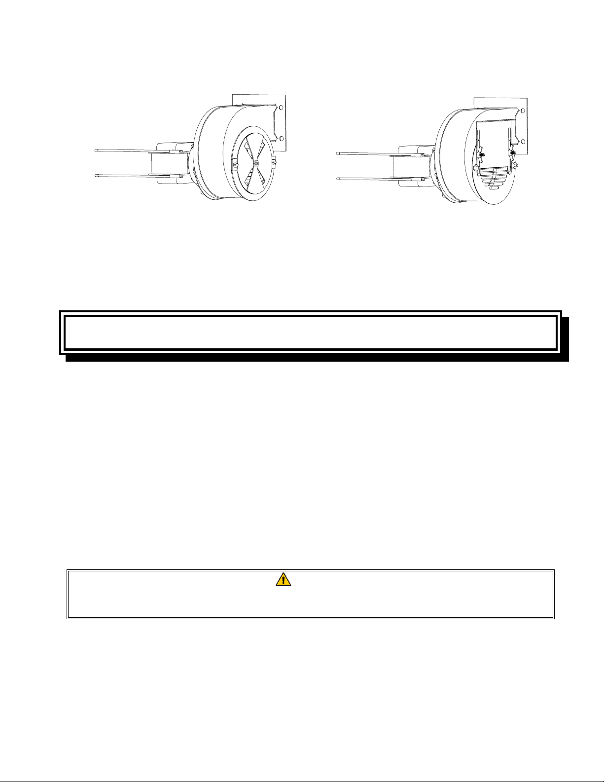
or close the air intake opening until a bright orange-red glow is obtained. Carefully hold the plate in
position and tighten the locking nut(s).
TYPICAL BLOWER ASSEMBLY
SOME CE BLOWER ASSEMBLIES
MAY BE CONFIGURED THIS WA Y
6.6 SEMI-ANNUAL CHECKS AND SERVICE
6.6.1 Clean Gas Valve Vent Tube
NOTE: This procedure is not required for fryers configured for export to CE
countries.
1. Set the fryer power switch and the gas valve to the OFF position.
2. Carefully unscrew the vent tube from the gas valve. NOTE: The vent tube may be straightened
for ease in removal.
3. Pass a piece of ordinary binding wire (.052 inch diameter) through the tube to remove any
obstruction.
4. Remove the wire and blow through the tube to ensure it is clear.
5. Reinstall the tube and bend it so that the opening is pointing downward.
6.6.2 Check Burner Manifold Pressure
DANGER
This task should be performed by qualified service personnel only. Contact your
FASC to arrange this service.
6.7 Annual/Periodic System Inspection
This appliance should be inspected and adjusted periodically by qualified service personnel as
part of a regular kitchen maintenance program.
6-5
Page 59

Frymaster recommends that a Factory Authorized Service Technician inspect this appliance at
least annually as follows:
6.7.1 Fryer
• Inspect the cabinet inside and out, front and rear for oil.
• Verify that the flue opening is not obstructed by debris or accumulations of solidified oil.
• Verify that burners and associated components (i.e. gas valves, pilot assemblies, ignitors, etc.)
are in good condition and functioning properly. Inspect all gas connections for leaks and verify
that all connections are properly tightened.
• Verify that the burner manifold pressure is in accordance with that specified on the appliance’s
rating plate.
• Verify that the temperature and high-limit probes are properly connected, tightened and
functioning properly, and that probe guards are present and properly installed.
• Verify that component box components (i.e. computer, transformers, relays, interface boards,
etc.) are in good condition and free from oil and other debris. Inspect the component box wiring
and verify that connections are tight and that wiring is in good condition.
• Verify that all safety features (i.e. drain safety switches, reset switches, etc.) are present and
functioning properly.
• Verify that the frypot is in good condition and free of leaks and that the frypot insulation is in
serviceable condition.
• Verify that wiring harnesses and connections are tight and in good condition.
6.7.2 Built-In Filtration System
• Inspect all oil-return and drain lines for leaks and verify that all connections are tight.
• Inspect the filter pan for leaks and cleanliness. If there is a large accumulation of crumbs in the
crumb basket, advise the owner/operator that the crumb basket should be emptied into a fireproof
container and cleaned daily.
• Verify that all O-rings and seals are present and in good condition. Replace O-rings and seals if
worn or damaged.
• Check filtration system integrity as follows:
− Verify that filter pan cover is present and properly installed.
With the filter pan empty, place each oil return handle, one at a time, in the ON position.
−
Verify that the pump activates and that bubbles appear in the oil of the associated frypot.
6-6
Page 60

− Close all oil return valves (i.e., place all oil return handles in the OFF position). Verify
proper functioning of each oil return valve by activating the filter pump using the lever on
one of the oil return microswitches. No air bubbles should be visible in any frypot.
− Verify that the filter pan is properly prepared for filtering, then drain a frypot of oil heated to
350°F (177°C) into the filter pan and close the frypot drain valve. Place the oil return handle
in the ON position. Allow all cooking oil to return to the frypot (indicated by bubbles in the
oil). Return the oil return handle to the OFF position. The frypot should have refilled in no
more than 2 minutes and 30 seconds.
6-7
Page 61

PROTECTOR® SERIES GAS FRYERS
CHAPTER 7: OPERATOR TROUBLESHOOTING
7.1 Introduction
This chapter provides an easy reference guide to some of the common problems that may occur
during the operation of your equipment. The troubleshooting guides that follow are intended to help
you correct, or at least accurately diagnose, problems with your equipment. Although the chapter
covers the most common problems reported, you may encounter problems that are not covered. In
such instances, the Frymaster Technical Services staff will make every effort to help you identify
and resolve the problem.
When troubleshooting a problem, always use a process of elimination starting with the simplest
solution and working through to the most complex. Most importantly, always try to establish a clear
idea of why a problem has occurred. Part of your corrective action involves taking steps to ensure
that it doesn’t happen again. If a controller malfunctions because of a poor connection, check all
other connections while you’re at it. If a fuse continues to blow, find out why. Always keep in mind
that failure of a small component may often be indicative of potential failure or incorrect functioning
of a more important component or system.
If you are in doubt as to the proper action to take, do not hesitate to call the Frymaster Technical
Service Department or your local Frymaster Factory Authorized Service Center for assistance.
Before calling a servicer or the Frymaster HOTLINE (1-800-551-8633):
• Verify that electrical cords are plugged in and that circuit breakers are on.
• Verify that gas line quick-disconnects are properly connected.
• Verify that any gas line cutoff valves are open.
• Verify that frypot drain valves are fully closed.
• Have your fryer’s model and serial numbers ready to give to the technician assisting
you.
DANGER
Hot oil will cause severe burns. Never attempt to move this appliance when filled
with hot cooking oil or to transfer hot cooking oil from one container to another.
DANGER
This equipment should be unplugged when servicing, except when electrical circuit
tests are required. Use extreme care when performing such tests.
This appliance may have more than one electrical power supply connection point.
Disconnect all power cords before servicing.
Inspection, testing, and repair of electrical components should be performed by an
authorized service agent only.
7-1
Page 62

7.2 Troubleshooting Fryers
7.2.1 Computer and Heating Problems
PROBLEM PROBABLE CAUSES CORRECTIVE ACTION
A. Press the ON/OFF switch to turn
the computer on.
B. Verify that the fryer is plugged in
and that the circuit breaker is not
tripped.
C. Call FASC.
No display on the
computer.
A. Computer not turned on.
B. No power to fryer.
C. Computer, wiring harness or other
component has failed.
A. Drain valve not fully closed. A. Verify that the drain valve is fully
closed.
B. Turn the gas valve knob to the
ON position.
C. Verify that any in-line manual
shut off and main cut-off is
open.
D. Verify that the quick-disconnect
fitting on the flexible gas line is
firmly connected to the fryer.
E. Verify that combustion air
blower is running. If not, call
FASC for service. If combustion
air blower is functional, clean
Fryer does not heat.
Or
Display shows
HELP with alarm
sounding. Heating
indicator is on, but
burners will not
light.
B. Gas valve is not turned on.
C. Manual gas shut off valve closed.
D. Improperly connected quick-
disconnect fitting on gas line.
E. Obstructed or failed combustion
air blower.
and adjust per instructions in
Chapter 6 of this manual.
Fryer is operating
normally, but
recovery is slow
when cooking.
Or Fryer is slow
coming out of melt
Dirty or obstructed combustion air
blower.
Clean and adjust per instructions
in Chapter 6 of this manual.
cycle and displays
HELP a short time
after coming out of
melt cycle.
Fryer is operating
normally, but
produces a popping
A. Dirty or obstructed combustion air
blower.
B. Dirty or obstructed gas valve vent
tube (non-CE fryers only).
A. Clean and adjust per instructions
in Chapter 6 of this manual.
B. Clean per instructions in Chapter
6 of this manual.
sound when burners
ignite.
C. Malfunctioning combustion air
blower.
C. If blower is slow to come up to
speed, contact FASC for service.
7-2
Page 63

PROBLEM PROBABLE CAUSES CORRECTIVE ACTION
Heat indicator is on
and blower is
running, but burner
Blown fuse on interface board or
ignition module.
Replace fuse.
will not ignite.
7.2.2 Error Messages and Display Problems
Problem Probable Causes Corrective Action
CM7 display is in
wrong temperature
scale (Fahrenheit or
Celsius).
CM 7 display shows
IGNITION
FAILURE.
CM7 display shows
hot-hi-1.
CM 7 display shows
HIGH temp.
CM7 display shows
LOW TEMP.
CM7 display shows
PROBE
FAILURE.
CM7 display shows
IGNITION
FAILURE.
CM 7 display shows
HOT-HI -1.
Incorrect display option programmed. See page 4-16 for instructions.
Open drain valve or problem with
latching circuitry.
Verify that the drain valve is fully
closed. If the problem continues
call your FASC.
This in an indication of a
Frypot temperature is more than
410ºF (210ºC) or, in CE countries,
395ºF (202ºC).
malfunction in the temperature
control circuitry, including a
failure of the high-limit thermostat.
Shut the fryer down immediately
and call your FASC.
Fryer temp is above setpoint.
Ensure setpoint is set correctly. If
problem persists call your FASC.
This display is normal when the
fryer is first turned on and may
appear for a short while if a large
Frypot temperature is between 180°F
(82°C) and 315°F (157°C).
batch of frozen product is added to
the frypot. If the display never
goes out, the fryer is not heating.
Shut the fryer down and call your
FASC.
Problem with the temperature
measuring circuitry including the
probe.
Shut the fryer down and call your
FASC.
Verify that the drain valves are
Open drain valve, failed computer,
failed transformer, open high-limit
thermostat.
fully closed. Using the ON/OFF
switch, turn the computer OFF and
then ON again. If this does not
correct the problem, call your
FASC.
Frypot temperature is more than
410ºF (210ºC) or, in CE countries,
Call your FASC.
395ºF (202ºC).
7-3
Page 64

Problem Probable Causes Corrective Action
Heat indicator off
upon initial startup.
Display shows hi or
hot with alarm
sounding.
Computer locks up.
7.2.3 Filtration Problems
PROBLEM PROBABLE CAUSES CORRECTIVE ACTION
Filter Pump won’t
start.
OR
Pump stops during
filtering.
Failed computer, damaged wiring
harness or connector.
Computer error.
A. Power cord is not plugged in or
circuit breaker is tripped.
B. Pump motor has overheated
causing the thermal overload
switch to trip.
C. Failed filter handle microswitch.
Test: If this is a multi-pot fryer,
attempt to operate the pump using
a different handle. If the pump
starts, the handle microswitch is
either out of alignment or has
failed.
When the handle is placed in the
ON position, the lever on the
microswitch should be firmly
pressed against the switch. If so,
the switch has failed. If not, the
switch is loose and/or misaligned.
D. Filter pump blockage.
Test: Close the drain valve and
pull the filter pan out from the
fryer. Activate the pump. If the
pump motor hums for a short time
then stops, the probable cause is
blockage of the pump itself.
Call your FASC.
Turn the computer OFF and then
ON again. If problem persists,
contact your FASC.
A. Verify that the power cord is fully
plugged in. Is so, verify that
circuit breaker is not tripped.
B. If the motor is too hot to touch
for more than a few seconds, the
thermal overload switch has
probably tripped. Allow the
motor to cool at least 45 minutes
then press the Pump Reset
Switch.
C. If the switch is loose, tighten the
nuts and bolts holding it in place,
ensuring that when the handle is
placed in the ON position, the
lever on the microswitch is
pressed firmly against the switch.
If the switch has failed, call
FASC.
D. Pump blockages are usually
caused by sediment build-up in
the pump due to improperly sized
or installed filter paper and failure
to use the crumb screen. Call
FASC.
7-4
Page 65

PROBLEM PROBABLE CAUSES CORRECTIVE ACTION
A. Paper/screen needs changed or
cleaned.
B. If using filter paper
configuration, verify that filter
Filter pump runs,
but oil return is very
slow and bubbling
oil occurs.
A. Paper/screen clogged.
B. Improperly installed filter pan
components.
C. Attempting to filter with oil that
is not hot enough.
screen is in bottom of pan with
paper on top of screen.
Verify that O-rings are present
and in good condition on filter
pan connection fitting.
C. In order to properly filter, the oil
should be at or near 350ºF
(177ºC).
Filter pump runs
but oil does not
return to frypot and
there is no bubbling
oil.
Blockage in filter pan suction tube.
Test: Close the drain valve and pull
the filter pan out from the fryer.
Activate the pump. If bubbling oil
occurs, there is a blockage in the
filter pan suction tube.
The blockage may be caused by
sediment buildup. Use a thin,
flexible wire to remove the
blockage. If the blockage cannot be
removed, call FASC.
7.2.4 Auto Top-Off Problems
Problem Probable Causes Corrective Action
A. Fryer temperature must be at
A. Fryer temperature too low.
B. Temperature of oil too cold.
Frypots won’t top
C. Supply line out of JIB.
D. CM7 not readdressed after ATO
off.
switch was switched on.
7.2.5 Basket Lift Problems
PROBLEM PROBABLE CAUSES CORRECTIVE ACTION
Basket lift
movement is jerky
Basket lift rods need lubrication.
and/or noisy.
least 300°F (149°C).
B. Ensure that oil is above 70°F
(21°C).
C. Ensure supply line is in JIB.
D. Switch all CM7 computers off
and then on again to readdress
system.
If problem persists call your FASC.
Apply a light coating of
™
Lubriplate
or similar lightweight
white grease to the rod and
bushings.
7-5
Page 66

Frymaster, L.L.C., 8700 Line Avenue, Shreveport, Louisiana 71106
TEL 1-318-865-1711 FAX (Parts) 1-318-219-7140 FAX (Tech Support) 1-318-219-7135
PRINTED IN THE UNITED STATES
SERVICE HOTLINE
1-800-551-8633
819-6339
APRIL 2007
 Loading...