

Page 1
*8195856*
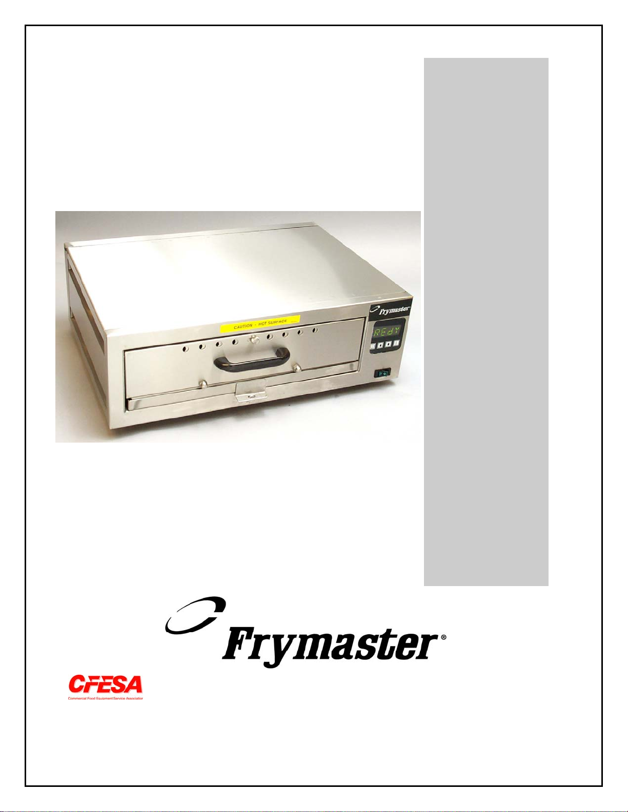
Installation, Operation, Service, and Parts Manual
Product Holding Device
Frymaster, a member of the Commercial Food Equipment Service Association, recommends
using CFESA Certified Technicians.
24-Hour Service Hotline
1-800-551-8633
JANUARY 2004
Page 2
NOTICE
IF, DURING THE WARRANTY PERIOD, THE CUSTOMER USES A PART FOR THIS ENODIS
EQUIPMENT OTHER THAN AN UNMODIFIED NEW OR RECYCLED PART PURCHASED
DIRECTLY FROM FRYMASTER/DEAN, OR ANY OF ITS AUTHORIZED SERVICE CENTERS,
AND/OR THE PART BEING USED IS MODIFIED FROM ITS ORIGINAL CONFIGURATION, THE
WARRANTY WILL BE VOID. FURTHER, FRYMASTER/DEAN AND ITS AFFILIATES WILL NOT BE
LIABLE FOR ANY CLAIMS, DAMAGES OR EXPENSES INCURRED BY THE CUSTOMER WHICH
ARISE DIRECTLY OR INDIRECTLY, IN WHOLE OR IN PART, DUE TO THE INSTALLATION OF
ANY MODIFIED PART AND/OR PART RECEIVED FROM AN UNAUTHORIZED SERVICE CENTER.
NOTICE
This appliance is intended for professional use only and is to be operated by qualified
personnel only. A Frymaster/DEAN Factory Authorized Service Center (FASC) or other qualified
professional should perform installation, maintenance, and repairs. Installation, maintenance,
or repairs by unqualified personnel may void the manufacturer’s warranty.
NOTICE
This equipment must be installed in accordance with the appropriate national and local codes of
the country and/or region in which the appliance is installed.
NOTICE TO U.S. CUSTOMERS
This device complies with Part 15 of the FCC rules. Operation is subject to the following two
conditions: 1) This device may not cause harmful interference, and 2) This device must accept
any interference received, including interference that may cause undesired operation. While
this device is a verified Class A device, it has been shown to meet the Class B limits.
NOTICE TO CANADIAN CUSTOMERS
This digital apparatus does not exceed the Class A or B limits for radio noise emissions as set
out by the ICES-003 standard of the Canadian Department of Communications.
Cet appareil numerique n’emet pas de bruits radioelectriques depassany les limites de classe A
et B prescrites dans la norme NMB-003 edictee par le Ministre des Communcations du Canada.
DANGER
Improper installation, adjustment, maintenance or service, and unauthorized alterations or
modifications can cause property damage, injury, or death. Read the installation, operating,
and service instructions thoroughly before installing, operating or servicing this equipment.
Do not operate the PHD unless it has been properly installed and checked.
Do not operate the PHD unless all covers and access panels are in place and properly secured.
Do not attempt to repair or replace any component of the PHD unless all power to the unit has
been disconnected.
Use caution when setting up, operating, or cleaning the PHD to avoid contact with heated
surfaces.
DANGER
Do not store or use gasoline or other flammable liquids or vapors in the vicinity of this or any
other appliance.
Page 3

Product Holding Device (PHD)
Installation, Operation, Service and Parts Manual
Section Page
1
2
3
4
5
6
7
8
9
10
11
12
Parts and Service Information
Description
Installation
Start-Up
Programming Setpoints
Changing Temperature Display
Operation
Cleaning
Service Procedures
Test Procedures
Troubleshooting
Parts
1
3
3
4
6
7
7
8
9
14
15
16
1. Parts and Service Information
1.1 U.S. Warranty Statement
The Frymaster LLC makes the following limited warranties to the original purchaser only for
this equipment and replacement parts:
Domestic Warranty Provisions – Product Holding Device
A. The Frymaster LLC warrants all components against defects in material and workmanship
for a period of 1 year.
B. All parts, with the exception of fuses, are warranted for 1 year after installation date of
cabinet.
C. If any parts, except fuses, become defective during the first year after installation date,
Frymaster will also pay straight-time labor costs to replace the part, plus up to 100 miles/160
km of travel (50 miles/80 km each way).
Parts Return
All defective in-warranty parts must be returned to a Frymaster Authorized Factory Service
Center within 60 days for credit. After 60 days, no credit will be allowed.
1
Page 4

Warranty Exclusions
This warranty does not cover equipment which has been damaged due to misuse, abuse,
alteration, or accident such as:
• improper or unauthorized repair;
• failure to follow proper installation instructions and/or scheduled maintenance
procedures.
• improper maintenance;
• damage in shipment;
• abnormal use;
• removal, alteration, or obliteration of the rating plate;
This warranty also does not cover:
• transportation or travel over 100 miles/160 km (50 miles/80 km each way), or travel
time over two (2) hours;
• overtime or holiday charges;
• consequential damages (the cost of repairing or replacing other property which is
damaged), loss of time, profits, use or any other incidental damages of any kind.
There are no implied warranties or merchantability or fitness for any particular use or purpose.
1.2 Service Information
Included with the unit when shipped from the factory is a list of Factory Authorized Service
Centers (FASCs). Refer to this list to find the FASC nearest you. If you do not have access to
this list, contact the Frymaster Technical Service Department at 1-800-551-8633 (USA and
Canada) or 1-318-865-1711 (Worldwide).
Service information may be obtained by contacting your local FASC. Information may also be
obtained by calling the Frymaster Technical Service Department at 1-800-551-8633
(USA/Canada) or 1-318-865-1711 (Worldwide). In order to assist you as quickly as possible,
the FASC or Service Department representative requires certain information about your
equipment. Most of this information is printed on a data plate located in the bottom right side
of your unit. When requesting service, please have the following information ready:
Model Number:
Serial Number:
Voltage:
Cabinet Mounted/Stand-alone:
In addition to the model number, serial number, and voltage, please be prepared to describe the
nature of the problem and have ready any other information that you think may be helpful in
solving your problem. Parts orders may be placed directly with your local FASC or distributor.
When ordering parts, the following information is required:
Model Number:
Serial Number:
Item Part Number:
Quantity Needed:
Voltage:
Cabinet Mounted/Stand-alone:
RETAIN AND STORE THESE INSTRUCTIONS IN A SAFE PLACE FOR FUTURE USE.
2
Page 5
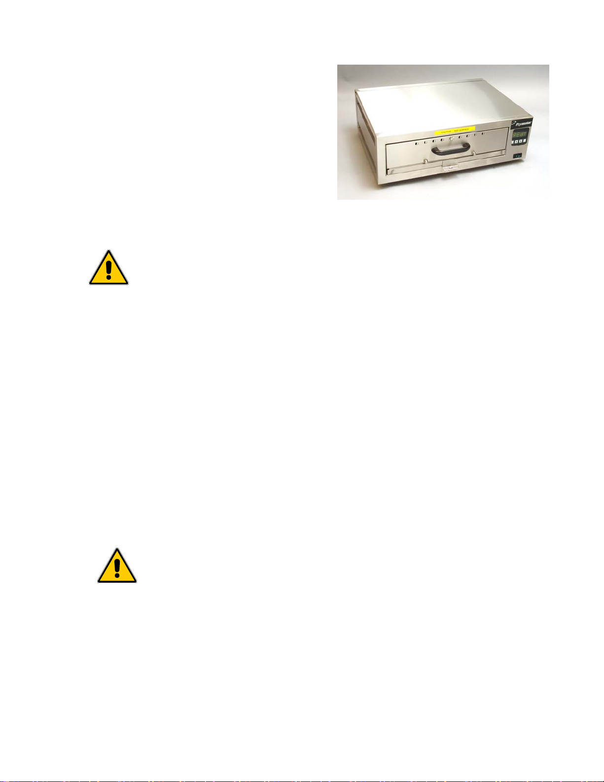
2. Description
The Frymaster Product Holding Device was
introduced in 1999. The PHD is designed to
extend product life by regulating humidity and
temperature. There are two models of the PHD,
one having a 3-inch deep drawer, the other
having a 4-inch deep drawer. Except for the
size of the drawer and cabinet, the two models
are identical.
• Safe and satisfactory operation of your equipment depends on its
proper installation.
• Installation must conform to local codes, or in the absence of local
codes, with the latest edition of your national electrical code, i.e.
National Electrical Code, NFPA 70 (USA); Canadian Electrical Code
Part 1, CSA-C22.1; or European Community Standards (CE).
3. Installation
1. Place the Product Holding Device on a firm, stable surface. Ensure there is adequate air
circulation around the device, particularly along the right side where ventilation slots
are located.
2. For the USA and Canada, the PHD comes configured for 120V/50/60HZ/1PH electrical
service. For export, the PHD comes configured for 230V/50Hz/1PH electrical service.
Before installing, inspect the rating plate found on the bottom right side of the device to
verify it is configured for the electrical service in your store.
3. The Product Holding Device is not suitable for outdoor use. When
operating this unit, it must be placed on a horizontal surface.
4. The Product Holding Device is not suitable for installation in an area
where a water jet can be used. This appliance must not be cleaned with a
water jet.
5. This unit is equipped with the appropriate, grounded plug for your
protection against shock hazard and should be plugged directly into a
properly grounded receptacle. Do not cut off, remove or otherwise bypass
the grounding prong on this plug.
6. If it is necessary to use an extension cord, it must be a three-conductor,
grounded cord of 16 gauge or greater.
3
Page 6
Unpacking the PHD and its components:
1. Check that the container is upright. Unpack the PHD carefully and remove all
accessories from the carton. Do not discard or misplace these, as they will be needed.
2. After unpacking, immediately check the equipment for visible signs of shipping
damage. If such damage has occurred, contact the carrier and file the appropriate
freight claims. Do not contact the factory, as the responsibility of shipping damage is
between the carrier and the dealer or end-user.
3. If your equipment arrives damaged:
4. File claim for damages immediately – Regardless of extent of damage.
5. Visible loss or damage – Be sure this is noted on the freight bill or express receipt and
is signed by the person making the delivery.
6. Concealed loss or damage – If damage is unnoticed until equipment is unpacked, notify
the freight company or carrier immediately, and file a concealed damage claim. This
should be done within 15 days of date of delivery. Be sure to retain container for
inspection.
NOTE: Frymaster does not assume responsibility for damage or loss incurred in transit.
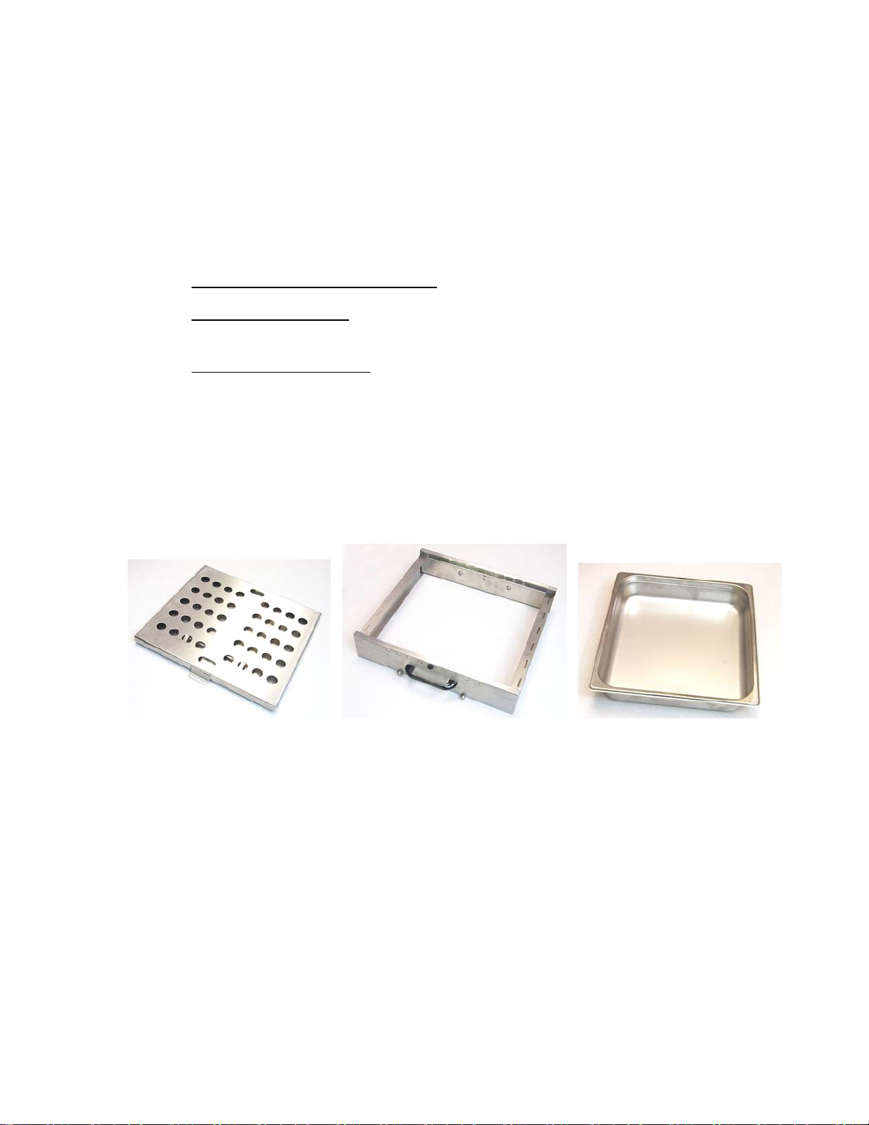
4. Start-Up
Water Tray Product Drawer Product Tray
4.1 Before Start-Up
● Clean product drawer, product tray and water tray components with soapy water, rinse,
and dry thoroughly.
● Assemble product drawer and water tray components.
● Insert the water tray into the Product Holding Device. Latch the water tray.
● Insert product drawer into the Product Holding Device.
4
Page 7

4.2 Start-Up
● Plug unit in to electrical power source
(if not already plugged in).
● Lift the water tray off the latch.
● While holding the product drawer, pull
the water tray out far enough to expose
the fill hole on the water tray.
● Fill water tray to ¼-inch (6mm) of top
edge.
● Push water tray in.
● Re-latch the water tray.
• Turn the unit ON by pushing the green ON/OFF switch. The ON/OFF markings are
— (ON) and O (OFF).
I
ON
Power Switch
OFF
Latch
Water Inlet
• Press on face of controller, which turns on the controller.
• Low appears on the display, and the unit begins to heat to setpoint.
• Within 25 minutes, both the top and bottom elements will heat to their
preprogrammed setpoints. NOTE: It is not unusual for the unit to rise above setpoint
during initial warm up. It may briefly display H I G H before stabilizing.
• R E d Y is displayed on the controller when the unit has stabilized and the setpoint is
reached. Product can now be placed in the drawer.
L O W .
Press start button and
unit heats to setpoint.
R E d Y .
REdY is displayed when the unit
is at operating temperature.
5
Page 8

5. Programming Setpoints
The top and bottom heating elements can be programmed to different setpoints, which should be
no more than 15°F (9°C) apart. Greater temperature differences between the elements can cause
over heating, and the unit will display H O T and shut off power to the heating elements. Switch
the unit off and back on at the rocker switch to reset.
Follow these procedures to set or adjust the setpoints.
1. Turn on power to the unit using the ON/OFF
switch.
Program
2. Press to turn the controller off. The
computer display goes blank.
Mode
Indicator
P
3. Press
indicating the computer is in program mode.
NOTE: Programming must be begun within
six seconds of accessing the program mode.
The computer turns itself off if the process is
not started quickly.
4. Press the buttons in that sequence.
5. The setpoint for the top heating element is displayed.
6. Use to raise or lower setting to desired temperature.
7. Press to lock in choice.
8. SAVE is displayed on screen briefly.
9. The setpoint for the bottom element is displayed.
10. Use to adjust to desired setting.
. P is displayed on the computer
ON/OFF
Raise Setpoint Lower Setpoint
11. Press to lock in choice.
12. Screen displays S A V E briefly and goes blank.
13. Press to turn controller on. Unit will raise or lower temperature to new setpoints,
displaying
14. The setpoint and actual temperature for the upper and lower heating elements can be
determined by following this sequence with the display reading
Press four times. In order of appearance, the temperatures shown will be the upper
element’s actual temperature, upper element’s setpoint; lower element’s actual temperature
and the lower element’s setpoint.
R E d Y when the new temperatures are reached.
R E d Y or L O W:
6
Page 9

6. Changing Temperature Display: Fahrenheit to Celsius
1. Turn off power to unit.
2. Press and hold as the unit is turned back on.
3. The display is converted to Celsius. Reverse process to return to Fahrenheit display.
7. Operation
Morning:
1. Prepare unit by following instructions found in Chapter 4. If holding moist product, fill the
water tray before beginning daily operations. The degree of moisture in the cabinet can be
regulated with the vent/slide on the cabinet door. NOTE: The PHD can be operated without
water in the tray when a dry product is being held.
2. The Product Holding Device is designed to operate with separate upper and lower setpoints.
Follow instructions in Section 5 to set or adjust setpoints. Frymaster recommends the upper
element be set to 170°F (77°C) and the lower unit at 175°F (79°C.)
3. Turn power switch ON. The Product Holding Device will begin heating to the setpoint
temperatures. LED 1 will light when the controller calls for heat.
L O W .
LED illuminates when the
computer calls for heat.
DANGER! THE OPERATOR WILL BE EXPOSED TO STEAM OR
VERY HOT AIR EMITTING FROM THE PHD WHEN THE UNIT IS
OPERATING. WEAR PROTECTIVE GLOVES WHEN WORKING
WITH AN OPERATING PHD. DO NOT PLACE EXPOSED FACE OR
HANDS NEAR PRODUCT HOLDING DEVICE WHEN OPENING OR
CLOSING PRODUCT DRAWER OR WATER TRAY.
4. Check the water tray periodically to ensure water tray is full. NOTE: The PHD can be
operated without water in the tray when a dry product is being held.
7
Page 10

End of the Day:
1.
Turn the Product Holding Device OFF.
Heated air and steam are present in the cabinet, which may cause injury to
the operator. Wear gloves when cleaning the unit. External cabinet surfaces
may be hot to touch.
2. Allow the unit to cool before cleaning.
3. Remove the product drawer and water tray assemblies. Clean the product drawer and water
tray, using mild detergent and water. Rinse off the product drawer and water tray. Dry
thoroughly and re-install in the Product Holding Device. See more detailed information in
Chapter 7, Cleaning, starting on page 9.
4. Wipe off the Product Holding Device cabinet exterior with a damp cloth using a mixture of
mild detergent and hot water. Dry cabinet.
The Product Holding Device must not be cleaned with a water jet. Using a
water jet on this device will void the warranty. Water pressure from the
water jet will damage the controllers and heating elements and or cause
electrical shorts in the device, which can injury the operator.
8. Cleaning
Wipe, do not spray. Water spray may come in contact with electrical
components due to water pressure. Wet electrical components may cause
serious injury to the operator and damage the Product Holding Device.
Periodic:
1. During the day, the external cabinet surfaces can be brushed with a soft brush to wipe away
crumbs or wiped with a clean cloth dampened with a solution of detergent and water.
Wear gloves when cleaning the unit. External cabinet surfaces may be hot to
touch.
2. If the product drawer is to be cleaned, remove the drawer before cleaning. Do not wipe clean
while the drawer is in the cabinet. Wipe the drawer with a slightly dampened cloth with a
solution of detergent and water. Dry thoroughly and replace the drawer into the cabinet.
Heated air and steam are present in the cabinet, which may cause injury to
the operator.
Daily:
1. Preparation: When the Product Holding Device is cool (such as before the unit is turned on
in the morning), and with the ON/OFF switch in the OFF position, remove the product
drawer and water tray.
8
Page 11

2. Cabinet Surfaces: Dampen a clean cloth with a solution of detergent and water and wipe
down all exposed metal surfaces. A Scotchbrite® or similar nylon scouring pad may be used
to remove stubborn residue from metal surfaces.
3. Removable Parts: The water tray and product drawer can be washed in the sink. Use a
solution of detergent and water to clean all surfaces. A Scotchbrite® or similar nylon scouring
pad may be used to remove stubborn residue from metal surfaces. Rinse residue off and
thoroughly dry before placing back into the Product Holding Device.
4. Reassembly:
a. Water Tray:
(1) Reassemble the water tray.
(2) Place the reassembled water tray back into the Product Holding Device cabinet.
(3) Fill the water tray to within ¼-inch (6mm) of top edge with fresh water. NOTE: The
PHD can be operated without water in the tray when a dry product is being held.
(4) Secure the tray by lifting onto the latch to lock in place.
b. Product Drawer:
(1) Reassemble the product tray.
(2) Slide the reassembled product drawer into the cabinet.
5. The Product Holding Device is now ready for future operation.
Wipe, do not spray. Water spray may come in contact with electrical
components due to water pressure. Wet electrical components may cause
serious injury to the operator and damage the Product Holding Device.
9 Service Procedures
9.1 Functional Description
When the switch is turned on, line voltage is supplied to the primary side of the 12VAC
transformer and to one side of the output terminal on the solid state relays (see wiring diagrams
on following page). The transformer supplies 12VAC to the computer, which rectifies the
voltage and sends approximately 12 VDC to control the opening and closing of the solid state
relays, sending line voltage to the heating elements.
When the computer is turned on, probes in the computer’s heater circuits measure temperatureinduced changes in their resistance and those signals are used to determine when the computer
closes the solid state relays, sending power to the heating elements. On the CE version of the
unit, a line filter is in the circuit above the load side of the transformer.
9
Page 12

12 VAC
Non-CE Wiring Diagram
12 VAC
CE Wiring Diagram
10
Page 13

9.2 Cabinet Disassembly
The cabinet must be substantially disassembled to gain access to the operating components.
Follow these steps to dismantle the unit prior to any component replacement.
• Disconnect the unit from the electrical power supply and allow it to cool.
• Remove tray and pan.
• Sit the unit face down and remove the eight screws securing the back.
• Compress the opening in the power cord strain relief with narrow-jaw pliers and remove.
• The back of the PHD must be removed to access the internal components. After removing
the screws, the cover slides off. If necessary, tap the edges (see left-hand photo below) with
a screwdriver and plastic mallet. Work from the side opposite the power cord, as shown in
the right-hand photo. NOTE: Silicon is used to seal the unit and resistance from the silicon
will be felt as the unit is disassembled.
• Remove the screws from the bottom of the unit.
• Gently spread the sides of the top assembly and lift it from unit.
• Remove insulation blanket.
• Slide bottom panel from unit if necessary. NOTE: Diagnostic tests can be performed on the
bottom heating element with the bottom panel in place. It is not necessary to remove the
bottom unless the bottom heating element needs to be replaced.
• To reassemble, reverse the steps. Reseal all joints and probes with silicone. NOTE: When
replacing the back, fit the power cord side of the panel on first and work toward the opposite
side. Tap the back into place with a non-marring plastic mallet.
11
Page 14

9.3 Replacing the Transformer, Relays, Computer, or Power Switch
To access components, follow the steps outlined in cabinet disassembly, 9.2.
• Identify the component to be replaced.
Computer
Power Switch
• Hold the replacement component next to the component to be replaced and, one at a time,
fasten wires from the failed component to their corresponding locations on the new unit.
• Remove the screws securing the failed component.
• Fasten replacement component into place.
Relay
Relay
12VAC
Transformer
• Test unit for proper operation prior to reassembling.
9.4 Replacing Temperature Probes
To access components, follow the steps outlined in cabinet disassembly, 9.2.
Top Probe
• With pin pusher, remove leads 3 and 5 from
computer plug.
• Remove screws securing probe to cabinetry.
• Disassemble insulating block holding probe.
• Position new probe in insulating block and
attach to cabinetry.
• Route wires to computer plug and insert
with pin pusher; red wire goes to 6.
Detail of Top Probe Assembly
12
Page 15

Bottom Probe
● With a pin pusher, remove leads 4 and 6
from the computer plug.
● Remove the nut securing the probe to its
stud and remove the probe.
● Position the replacement probe in the
insulating block and attach the block to the
cabinet.
● Route the wires to the computer plug and
insert with pin pusher (the red wire goes to
pin 4).
Detail of Bottom Probe Assembly
9.5 Heating Element Replacement
To access components, follow the steps outlined in cabinet disassembly, 9.2.
Remove the screws securing the heater cover.
Top Element
• Remove the leads from the element.
• Position the new heating element.
• Attach the blue lead to the element terminal
nearest the computer.
• Attach the white lead to the opposite
element terminal.
Bottom Element
• Remove the leads from the element.
• Position the new heating element.
View of the Top Heating Element
• Attach the red lead to the element terminal
nearest the computer.
• Attach the white lead to the opposite
element terminal.
13
Page 16

10 Test Procedures
To access components for all tests, follow the steps outlined in cabinet disassembly, 9.2.
10.1 Relays
• With power supplied and the computer
turned on, measure DC voltage across input
terminals of relay. With the computer
calling for heat (dot illuminated on display),
the reading should be approximately 4.5
VDC. Absence of DC voltage indicates a
problem with the computer.
Relay Output and Input Terminals
• With power supplied and the computer turned on and calling for heat (dot illuminated in
display), measure AC voltage across the output terminals of the relay. The reading should be
approximately .9 VAC. The presence of line voltage with the computer calling for heat
indicates a failure of the computer to supply the necessary DC voltage to close the relay or a
failure of the relay itself.
OUTPUT
INPUT
10.2 Transformer
Line voltage should be measured across the input side of the transformer; 12 VAC should be
measured across the output side.
10.3 Heating Elements
Resistance measurements are taken with the unit turned off. Resistance for the top element
should be approximately 58 ohms; for the bottom, approximately 26 ohms.
10.4 Probes
Measure the resistance of the probes when the unit is cool. The top probe is measured across
pins 3 and 5. The bottom probe is measured across pins 4 and 6. Measured resistance should
be approximately equal to that shown in the table below.
Fahrenheit Ohms Celsius Fahrenheit Ohms Celsius
70 1080 21 190 1330 88
80 1101 27 200 1350 93
90 1122 32 210 1371 99
100 1143 38 220 1391 104
110 1164 43 230 1412 110
120 1185 49 240 1432 116
130 1206 54 250 1453 121
140 1226 60 260 1473 127
150 1247 66 270 1493 132
160 1268 71 280 1514 138
170 1289 77 290 1534 143
180 1309 82 300 1554 149
14
Page 17

11 Troubleshooting
Problem Probable Causes Corrective Action
Loose connection between
the relay output and
heating element or loose
connection between the
relay input and incoming
line voltage.
Either heating element
fails to heat
Computer does not
activate
Loose connection on the
input side of relay.
Failed heating element
Failed transformer
Failed switch
With the computer calling for heat,
check for line voltage across the
heating element terminals. If line
voltage is not present, ensure all
connections are solid.
With the computer calling for heat,
check for approximately 5 VDC
across the input side of the relay. If
not present, check for 5VDC between
pin 1 of the computer plug and ground
for the upper relay and between pin 2
and ground for the lower relay. If not
present, the computer has failed. If
5VDC is present at computer plug, the
relay has failed.
With power removed from the unit,
measure resistance across the element
terminals. Correct readings are
approximately 58 ohms on the top and
26 ohms on the bottom.
Check for line voltage at the input
terminals of the transformer. If
present, check for 12VAC at the
output terminals of transformer. If not
present, replace transformer
Check for presence of line voltage at
outside terminals of switch. If present
at the switch but not at the input side
of the transformer, replace the switch.
Unit fails to reach or
to maintain setpoint
No line voltage
Failed temp probe
Failed computer
Ensure the unit is fully plugged into
the outlet.
With the unit cool, measure the
resistance of the probes.
Top probe is measured across pins 3
and 5. See the resistance chart on page
14.
Bottom probe is measured across pins
4 and 6. See the resistance chart on
page 14.
If temperature probe resistances are
correct, check the relays and the
heating elements.
15
Page 18

12 Parts
14
28
23
27
6
22
1
3
7
4
See Probe Assembly Detail
See assembly detail below
26
19
29
181716
25
24
20
181716
15
5
5
8
2
13
21
30
31
10
9
11
Detail of Probe Assembly Components
12
34
37
33
35
36
32
34
35
12
9
16
Page 19

Item Part # Description
p
(f
)
(f
))
)
p
f
(
)
(
)
(
)
(
)
(
)
r
(
)
y
(
)
(
y)
(
)
(
y)
d
(
)
(
y)
)
)
(
)
1 106-1384SP Computer Assembly, Non-CE Complete
2 106-2340 Computer and Mount Assembly, Universal
3 106-2339 Component and Mount Assembly, Non-CE
4 106-2357 Component and Mount Assembly, CE
5 807-3533 Relay, Solid State 18 Am
6 807-0855 Transformer 120V
7 807-3185 Transformer 230V, CE
8 106-1550 Line Filter Assembly, CE
or filter only, order 807-2818
9 807-3621 Sensor, 1000 OHM RTD
10 816-0555 Insulation, Probe
11 809-0895 Rivet, Solid Aluminum
12 816-0569 Cover, Probe
13 106-1916 Foot Assembly
or rubber pad only, order 826-1561 (pkg. of 4
14 826-1379 Screw, #10 X ½-inch (pkg. of 10
15 823-3738 Base
16 210-2165 Pan, Element
17 809-0190 Washer, ¼-inch S/S Flat
18 809-0055 Nut, 10-32 S/S Hex
19 Element, 250W To
807-3647 120V
807-3544 240V
20 Element, 500W Bottom
807-3646 120VAC
807-3543 240V
21 816-0564 Insulation, Top and Bottom
22 816-0565 Insulation, Right Side
23 Bushing, Strain Relie
807-2950 Non-CE
807-1694 CE
24 823-3407 Cavity and Front Panel, 3-inch
25 823-3378 Top, 3-inch Cabinet
order 823-4343 for 4-inch cabinets
26 824-0934 Panel, 3-inch Cabinet Rear
27 210-2425 Shield, 3-inch Cavity Heat
28 210-2439 Cover, 3-inch Rear
order 210-5540 for 4-inch cabinets
order 824-4344 for 4-inch cabinets
order 824-1207 for 4-inch cabinets
order 210-5445 for 4-inch cabinets
29 807-2734 Switch, 120V Green Lighted ON/OFF Rocke
30 823-3423 Tray, 3-inch Water
order 823-4365 for 4-inch cabinets
31 Insert, Water Tra
823-3414 Single-Sided, 3-inch
823-3426 Double-Sided, 3-inch
order 823-4363 for 4-inch cabinets
used on 3-inch pass through units onl
32 Drawer, Full
106-1483 One-Handled, 3-inches Deep
106-1560 Two-Handled, 3-inches Deep
order 106-3442 for 4-inch cabinets
used on 3-inch pass through units onl
33 Drawer, Divide
106-1559 One-Handled, 3-inches Deep
106-1545 Two-Handled, 3-inches Deep
order 106-3293 for 4-inch cabinets
used on 3-inch pass through units onl
34 809-0890 Knurled Nut (Included in Items 31 and 32
35 810-0180 Handle, Drawer (Included in Items 31 and 32
36 803-0290 Pan, Full-Size
37 803-0298 Pan, Half-Size
* 807-0154 Cordset, 100-120V
order 806-4003 for 208-240V units
* Not illustrated.
17
Page 20

Frymaster, L.L.C., 8700 Line Avenue, PO Box 51000, Shreveport, Louisiana 71135-1000
Shipping Address: 8700 Line Avenue, Shreveport, Louisiana 71106
TEL 1-318-865-1711 FAX (Parts) 1-318-688-2200 (Tech Support) 1-318-219-7135
24-HOUR SERVICE HOTLINE
PRINTED IN THE UNITED STATES
1-800-551-8633
SEPTEMBER 2003
819-5856
 Loading...