

Page 1
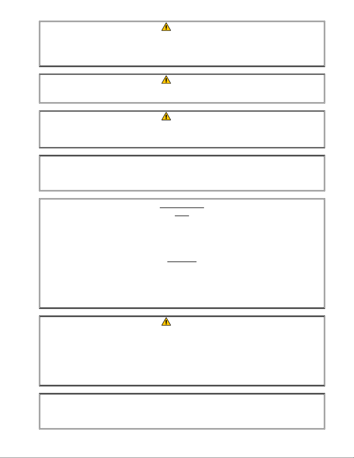
G18FB & G24FB Series Gas Fryers
Installation & Operation Manual
Frymaster, a member of the Commercial Food Equipment Service Association, recommends
using CFESA Certified Technicians.
24-Hour Service Hotline 1-800-551-8633
819-5654
05-98
Page 2
DANGER
IMPROPER INSTALLATION, ADJUSTMENT, ALTERATION, SERVICE, OR
MAINTENANCE CAN CAUSE PROPERTY DAMAGE, INJURY, OR DEATH. READ THE
INSTALLATION, OPERATING, AND SERVICE INSTRUCTIONS THOROUGHLY
BEFORE INSTALLING OR SERVICING THIS EQUIPMENT.
DANGER
FOR YOUR SAFETY, DO NOT STORE OR USE GASOLINE OR OTHER FLAMMABLE
LIQUIDS OR VAPORS IN THE VICINITY OF THIS OR ANY OTHER APPLIANCE.
DANGER
POST IN A PROMINENT LOCATION THE INSTRUCTIONS TO BE FOLLOWED IN THE
EVENT THE USER SMELLS GAS. THIS INFORMATION SHALL BE OBTAINED BY
CONSULTING THE LOCAL GAS SUPPLIER.
THIS EQUIPMENT IS TO BE INSTALLED IN COMPLIANCE WITH THE BASIC
PLUMBING CODE OF THE BUILDING OFFICIALS AND CODE ADMINISTRATORS
INTERNATIONAL, INC. (BOCA) AND THE FOOD SERVICE SANITATION MANUAL OF
THE FOOD AND DRUG ADMINISTRATION.
COMPUTERS
FCC
This device complies with Part 15 of the FCC rules. Operation is subject to the following two
conditions: 1) This device may not cause harmful interference, and 2) This device must accept any
interference received, including interference that may cause undesired operation. While this device is
a verified Class A device, it has been shown to meet the Class B limits.
CANADA
This digital apparatus does not exceed the Class A or B limits for radio noise emissions as set out by
the ICES-003 standard of the Canadian Department of Communications.
Cet appareil numerique n’emet pas de bruits radioelectriques depassany les limites de classe A et B
prescrites dans la norme NMB-003 edictee par le Ministre des Communcations du Canada.
DANGER
THIS PRODUCT CONTAINS CHEMICALS KNOWN TO THE STATE OF CALIFORNIA
TO CAUSE CANCER AND/OR BIRTH DEFECTS OR OTHER REPRODUCTIVE HARM.
Operation, installation, and servicing of this product could expose you to airborne
particles of glasswool or ceramic fibers, crystalline silica, and/or carbon monoxide.
Inhalation of airborne particles of glasswool or ceramic fibers is known to the State
of California to cause cancer. Inhalation of carbon monoxide is known to the State
of California to cause birth defects or other reproductive harm.
FRYMASTER FRYERS EQUIPPED WITH LEGS ARE FOR PERMANENT
INSTALLATION. FOR MOVEABLE OR PORTABLE INSTALLATION, FRYMASTER
OPTIONAL EQUIPMENT CASTERS MUST BE USED.
QUESTIONS??? CALL 1-800-551-8633.
Page 3

G18FB & G24FB SERIES GAS FRYERS
TABLE OF CONTENTS
CHAPTER 1: General Information
1.1 Parts Ordering and Service Information............................................................................ 1-1
1.2 Safety Information............................................................................................................. 1-1
1.3 Equipment Description...................................................................................................... 1-2
1.4 Installation, Operating, and Service Personnel ................................................................. 1-2
1.5 Definitions......................................................................................................................... 1-3
1.6 Shipping Damage Claim Procedure.................................................................................. 1-3
CHAPTER 2: Installation Instructions
2.1 General Installation Requirements.................................................................................... 2-1
2.2 Caster/Leg Installation ......................................................................................................2-2
2.3 Pre-Connection Preparations............................................................................................. 2-3
2.4 Connection to Gas Line..................................................................................................... 2-3
2.5 Converting to Another Gas Type ...................................................................................... 2-5
CHAPTER 3: Operating Instructions
3.1 Start-Up Procedure............................................................................................................ 3-1
3.2 Boiling-Out the Frypot......................................................................................................3-2
3.3 Shutting the Fryer Down...................................................................................................3-2
3.4 Controller Operation and Programming............................................................................ 3-3
Computer Magic III Controller ......................................................................................... 3-3
Analog Controller.............................................................................................................. 3-7
CHAPTER 4: Filtration Instructions
4.1 Draining and Manual Filtering.......................................................................................... 4-1
4.2 Built-In Filtration System Operation................................................................................. 4-1
Preparing the Filter Unit for Use....................................................................................... 4-2
Operation of the Filter Unit............................................................................................... 4-3
Changing the Filter Paper.................................................................................................. 4-5
CHAPTER 5: Preventive Maintenance
5.1 Fryer Preventive Maintenance Checks and Services ........................................................ 5-1
Daily Checks and Services................................................................................................ 5-1
Weekly Checks and Services ............................................................................................ 5-1
Monthly Checks and Services...........................................................................................5-2
Quarterly Checks and Services.......................................................................................... 5-3
Semi-Annual Checks and Services.................................................................................... 5-6
5.2 Built-In Filtration System Preventive Maintenance Checks and Services........................ 5-7
CHAPTER 6: Operator Troubleshooting
6.1 Introduction....................................................................................................................... 6-1
6.2 Troubleshooting Fryers and Controllers ........................................................................... 6-2
i
Page 4

G18FB & G24FB SERIES GAS FRYERS
TABLE OF CONTENTS
6.3 Troubleshooting the Built-In Filtration System .................................................................6-5
6.4 Replacing the Controller....................................................................................................6-8
ii
Page 5
G18FB & G24FB SERIES GAS FRYERS
CHAPTER 1: GENERAL INFORMATION
1.1 Parts Ordering and Service
Information
In order to assist you quickly, the Frymaster
Factory Authorized Service Center (FASC) or
Service Department representative requires
certain information about your equipment.
Most of this information is printed on a data
plate affixed to the inside of the fryer door.
Part numbers are found in the Installation, Operation, Service, and Parts Manual.
Parts orders may be placed directly with your
local FASC or distributor. Included with
fryers when shipped from the factory is a list
of Frymaster FASCs and Distributors. If you
do not have access to this list, contact the
Frymaster Service Department at 1-800-5518633 or 1-318-865-1711.
When ordering parts, the following information is required:
describe the nature of the problem and have
ready any other information that you think
may be helpful in solving your problem.
RETAIN AND STORE THIS MANUAL IN
A SAFE PLACE FOR FUTURE USE.
1.2 Safety Information
Before attempting to operate your unit, read
the instructions in this manual thoroughly.
Throughout this manual, you will find notations enclosed in double-bordered boxes
similar to the one below.
CAUTION boxes contain information about
actions or conditions that may cause or result
in a malfunction of your system.
CAUTION
Example of a CAUTION box.
Model Number:
Serial Number:
Type of Gas or Voltage:
Item Part Number:
Quantity Needed:
Service information may be obtained by
contacting your local FASC/Distributor.
Service may also be obtained by calling the
Frymaster Service Department at 1-800-5518633 or 1-318-865-1711.
When requesting service, please have the following information ready:
Model Number:
Serial Number:
Type of Gas:
In addition to the model number, serial number, and type of gas, please be prepared to
WARNING boxes contain information about
actions or conditions that may cause or result
in damage to your system, and which may
cause your system to malfunction.
WARNING
Example of a WARNING box.
DANGER boxes contain information about ac-
tions or conditions that may cause or result in
injury to personnel, and which may cause
damage to your system and/or cause your system to malfunction.
DANGER
Hot cooking oil or shortening causes
severe burns. Never attempt to move a
fryer containing hot cooking
oil/shortening or to transfer hot
cooking oil/shortening from one
container to another.
1-1
Page 6

G18FB & G24FB SERIES GAS FRYERS
CHAPTER 1: GENERAL INFORMATION
Your fryer is equipped with automatic safety
features:
1. High temperature detection shuts off gas to
the burner assembly should the controlling
thermostat fail.
2. An optional safety switch built into the
drain valve prevents burner ignition with
the drain valve even partially open.
1.3 Equipment Description
The G18FB and G24FB Series of gas fryers
are designed as liquid-batter style units. They
are capable of producing up to 50 pounds/25
liters (G18FB) or 65 pounds/36 liters (G24FB)
per hour of uniformly cooked fish, shrimp,
chicken, tempura, and similar products. The
fryers in this series employ an infrared burner
system to generate 80,000 BTU/hr (20,000
kcal, 84.4 megajoules, 23.4 kW).
into the center of the frypot, with a frontoperated manual ball valve. Heating is supplied by a pair of burner assemblies mounted
beneath the frypot. Combustion air for the
burners is supplied by a dedicated blower.
Each frypot is equipped with a temperature
probe for precise temperature control. The
probe is located on the centerline of the frypot
for rapid response to changes in loads, and to
provide the most accurate temperature measurement.
The fryers in this series can be configured for
natural gas or Propane (LP) gas, as required by
the customer.
All fryers come standard with electronic ignition. Control options include Computer Magic
III com put er s or sol id -st at e an alo g co ntr ol ler s.
Each type is covered in detail in Chapter 3,
Operating Instructions.
Fryers may be ordered without any built-in
filtration capability (G18FB/G24FB) or ready
for attachment to an existing Filter Magic II
filtration system (FG18FB/FG24FB). The fryers can also be ordered with a Filter Magic II
system positioned on either side of the fryer
(FMG18FB/FMG24FB). Additionally, up to
four units can be batteried to either side of a
Filter Magic II built-in filtration system to create a high-production frying station. In
January 1998, the FPG18FB variant entered
production, adding the advantages of the
FootPrint III built-in filtration system to the
earlier Filter Magic option.
All fryers in this series are of an open-pot,
flat-bottomed design with no tubes, which
makes cleaning the frypot quick and easy.
Frypots are constructed of welded heavygauge stainless steel. A drain valve is tapped
All fryers in this series require an external
source of AC electrical power. Units can be
configured for voltages ranging from 120
VAC to 220 VAC.
Fryer s eq uip ped wit h Foo tP rin t III bu ilt-in filtration systems are shipped completely
assembled. Fryers without the FootPrint III
require installation of legs or optional casters
at point of use. All fryers are shipped with a
package of standard accessories. Each fryer is
adjusted, tested, and inspected at the factory
before crating for shipment.
1.4 Installation, Operating, and
Service Personnel
Operating information for this equipment has
been prepared for use by qualified and/or
1-2
Page 7

G18FB & G24FB SERIES GAS FRYERS
CHAPTER 1: GENERAL INFORMATION
authorized personnel only, as defined in Section 1.5.
All installation and service on Frymaster
equipment must be performed by qualified,
certified, licensed, and/or authorized
installation or service personnel, as d efined
in Section 1.5.
1.5 Definitions
A list of Frymaster Factory Authorized Service Centers (FASC) was included with the
fryer when shipped from the factory. Failure
to use qualified service personnel will void
the Frymaster Warranty on your equipment.
1.6 Shipping Damage Claim
Procedure
QUALIFIED AND/OR AUTHORIZED OPERATING
PERSONNEL
Qualified/authorized operating personnel are
those who have carefully read the information
in this manual and have familiarized themselves with the equipment functions, or who
have had previous experience with the operation of the equipment covered in this manual.
QUALIFIED INSTALLATION PERSONNEL
Qualified installation personnel are individuals, firms, corporations, and/or companies
which, either in person or through a representative, are engaged in and are responsible for
the installation of gas-fired appliances. Qualified personnel must be experienced in such
work, be familiar with all gas precautions involved, and have complied with all
requirements of applicable national and local
codes.
QUALIFIED SERVICE PERSONNEL
Qualified service personnel are those who are
familiar with Frymaster equipment and who
have been authorized by
Frymaster
FrymasterFrymaster
Corpora-
Frymaster
tion to perform service on Frymaster
equipment. All authorized service personnel
are required to be equipped with a complete
set of service and parts manuals, and to stock a
minimum amount of parts for Frymaster
equipment.
Your Frymaster equipment was carefully inspected and packed before leaving the factory.
The transportation company assumes full responsibility for safe delivery upon its
acceptance of the equipment for transport.
What to do if your equipment arrives
damaged:
1. File a claim for damages immediately,
regardless of the extent of damages.
2. Inspect for and record all vi sible loss or
damage, and ensure that this information
is noted on the freight bill or express receipt and is signed by the person making
the delivery.
3. Concealed loss or damage that was un-
noticed until the equipment was unpacked
should be recorded and reported to the
freight company or carrier immediately
upon discovery. A concealed damage
claim must be submitted within 15 days of
the date of delivery. Ensure that the shipping container is retained for inspection.
Frymaster
Frymaster
FrymasterFrymaster
RESPONSIBILITY FOR DAMAGE OR LOSS
INCURRED IN TRANSIT.
DOES NOT ASSUME
1-3
Page 8

G18FB & G24FB SERIES GAS FRYERS
CHAPTER 2: INSTALLATION INSTRUCTIONS
2.1 General Installation
Requirements
PROPER INSTALLATION IS ESSENTIAL FOR
EFFICIENT, TROUBLE-FREE OPERATION OF
YOUR FRYER. ANY UNAUTHORIZED ALTERATIONS MADE TO THIS EQUIPMENT WILL
VOID THE FRYMASTER
WARRANTY.
Upon arrival, inspect the fryer carefully for
visible or concealed damage. (See Shipping
Damage Claim Procedure in Chapter 1.)
CLEARANCE AND VENTILATION
The fryer(s) must be installed with a 6” (150
mm) clearance at both sides and back when
installed adjacent to combustible construction;
no clearance is required when installed adjacent to noncombustible construction. A
minimum of 24” (600 mm) clearance should
be provided at the front of the fryer(s). Air for
combustion enters the fryer(s) below the cabinet base.
One of the most important considerations of
efficient fryer operation is ventilation. Make
sure the fryer is installed so that products of
combustion are removed efficiently, and that
the kitchen ventilation system does not produce drafts that interfere with proper burner
operation.
The fryer flue opening must not be placed
close to the intake of the exhaust fan, and the
fryer must never have its flue extended in a
“chimney” fashion. An extended flue will
change the combustion characteristics of the
fryer, causing longer recovery time. It also
frequently causes delayed ignition. To provide the airflow necessary for good combustion and burner operation, the areas surrounding the fryer front, sides, and rear must be kept
clear and unobstructed.
Fryers must be installed in an area with an
adequate air supply and adequate ventilation.
Adequate distances must be maintained from
the flue outlet of the fryer to the lower edge of
the ventilation filter bank. Filters should be
installed at an angle of 45º. Place a drip tray
beneath the lowest edge of the filter. For U.S.
installation, NFPA standard No. 96 states, “A
minimum distance of 18 in. (450 mm) should
be maintained between the flue outlet and the
lower edge of the grease filter.” Frymaster
recommends that the minimum distance be 24
in. (600 mm) from the flue outlet to the bottom
edge of the filter.
Information on construction and installation of
ventilating hoods can be found in the NFPA
standard cited above. A copy of the standard
may be obtained from the National Fire Protection Association, Battery March Park,
Quincy, MA 02269.
DANGER
Do not attach an apron drainboard to a
single fryer. The fryer may become
unstable, tip over, and cause injury.
The appliance area must be kept free
and clear of combustible material at all
times.
NATIONAL CODE REQUIREMENTS
The type of gas for which the fryer is equipped
is stamped on the data plate attached to the
inside of the fryer door. Connect a fryer
stamped “NAT” only to natural gas, and
those stamped “PRO” only to propane gas.
Installation shall be made with a gas connector
that complies with national and local codes.
Quick-disconnect devices, if used, shall likewise comply with national and local codes.
2-1
Page 9

G18FB & G24FB SERIES GAS FRYERS
CHAPTER 2: INSTALLATION INSTRUCTIONS
ELECTRICAL GROUNDING REQUIREMENTS
All electrically operated appliances must be
grounded in accordance with all applicable
national and local codes. A wiring diagram is
located on the inside of the fryer door. Refer
to the rating plate on the inside of the fryer
door for proper voltages.
DANGER
If this appliance is equipped with a
three-prong (grounding) plug, it must
be plugged directly into a properly
grounded receptacle.
Do not cut or remove the grounding
prong from the plug.
DANGER
This equipment requires electrical
power for operation.
Place the gas control valve in the OFF
position in case of a prolonged power
outage.
Do not attempt to use the equipment
during a power outage.
rules. While these devices are verified as
Class A devices, they have been shown to
meet the Class B limits. These limits are designed to provide reasonable protection
against harmful interference when the equipment is operated in a commercial environment. This equipment generates, uses, and can
radiate radio frequency energy and, if not installed and used in accordance with the instruction manual, may cause harmful interference to radio communications. Operation of
the equipment in a residential area is likely to
cause harmful interference in which case the
user will be required to correct the interference
at his own expense.
If necessary, the user should consult the dealer
or an experienced radio and television technician for additional suggestions.
The user may find the booklet “How to Identify and Resolve Radio-TV Interference Problems” helpful. It is prepared by the Federal
Communications Commission and is available
from the U.S. Government Printing Office,
Washington, DC 20402, Stock No. 004-00000345-4.
2.2 Caster/Leg Installation
FCC COMPLIANCE
The user is cautioned that any changes or
modifications to Frymaster computers not expressly approved by the party responsible for
compliance could void the user’s authority to
operate the equipment.
Frymaster computers have been tested and
found to comply with the limits for a Class A
digital device, pursuant to Part 15 of the FCC
Depending upon the specific configuration
ordered, your fryer may have been shipped
without installed casters or legs. If casters or
legs are installed, you may skip this section
and proceed to section 2.3, Pre-Connection
Preparations.
If your fryer requires the installation of
casters/legs, install them in accordance with
the instructions inclu ded in your accessory
package.
2-2
Page 10
G18FB & G24FB SERIES GAS FRYERS
CHAPTER 2: INSTALLATION INSTRUCTIONS
2.3 Pre-Connection Preparations
DANGER
Do not connect fryer to gas supply
before completing each step
in this section.
After the fryer has been positioned under the
fry station exhaust hood, ensure the following
has been accomplished:
1. Adequate means must be provided to limit
the movement of fryers without depending
upon the gas line connections. If a flexible
gas hose is used, a restraining cable must
be connected at all times when the fryer is
in use. The restraining cable and installation instructions are packed with the flexible hose in the accessories box that was
shipped with your unit.
2. Single unit fryers must be stabilized by
installing restraining chains on fryers
equipped with casters or anchor straps on
fryers equipped with legs. Follow the instructions shipped with the casters/legs to
properly install the chains or straps.
3. Level fryers equipped with legs by screw-
ing out the legs approximately 1 inch then
adjusting them so that the fryer is level and
at the proper height in the exhaust hood.
Frymaster
Frymaster
FrymasterFrymaster
recommends that the minimum
distance from the flue outlet to the bottom
edge of the filter be 24 in. (600 mm).
4. Test the fryer electrical system:
a. Plug the fryer electrical cord(s) into a
grounded electrical receptacle.
b. Place the power switch in the ON
position.
• For fryers equipped with analog
controls, verify that the power and
heat lights are lit.
• For fryers having computers, verify
that the display indicates CYCL.
c. Place the fryer power switch in the
OFF position. Verify that the power
and heat lights are out, or that the display is blank.
5. Refer to the data plate on the inside of the
fryer door to determine if the fryer burner
is configured for the proper type of gas before connecting the fryer to the gas supply
line.
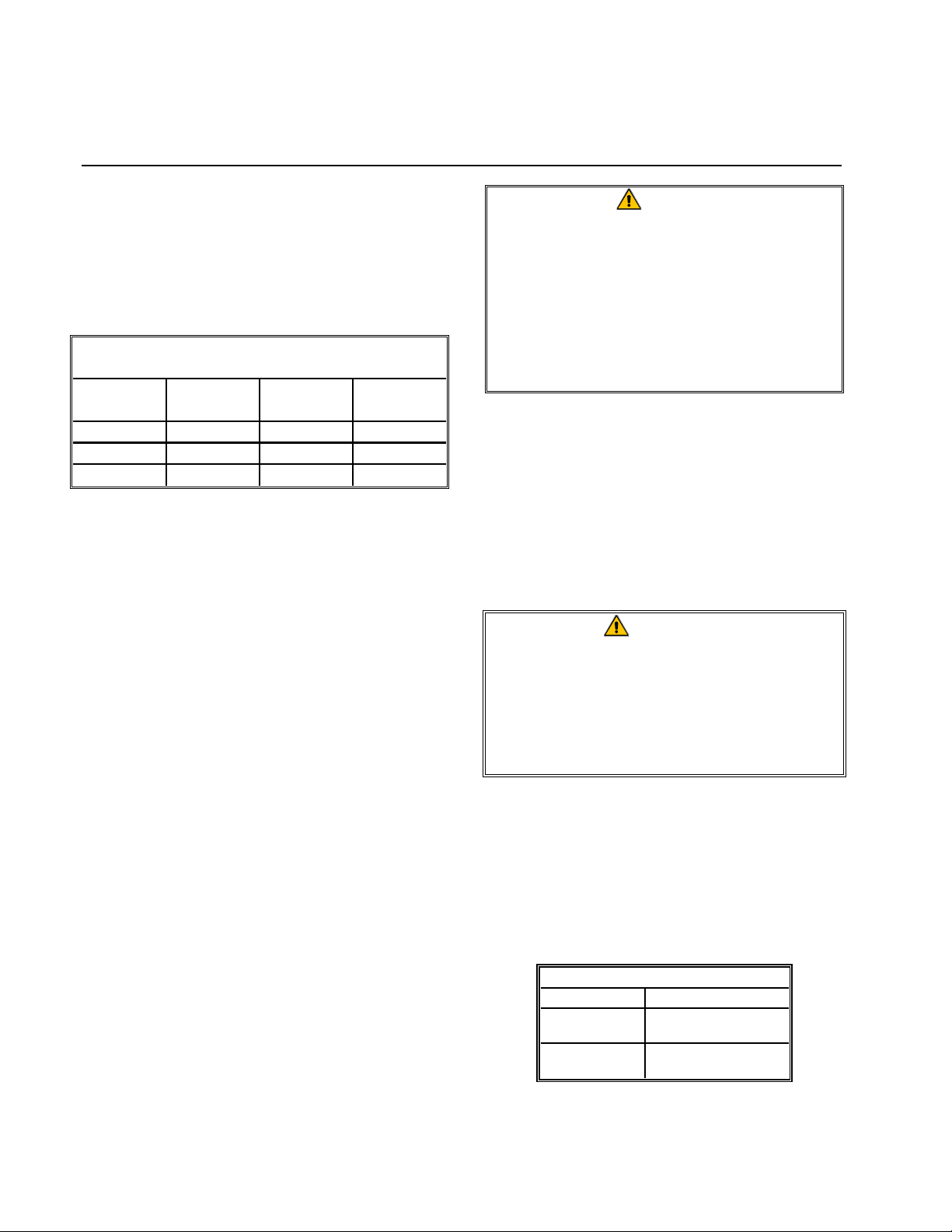
6. Verify the minimum and maximum gas
supply pressures for the type of gas used in
accordance with the table below.
Incoming Gas Pressures
Gas Minimum Maximum
Natural
LP
6" W.C.
1.49 kPa
14.93 mbar
11" W.C.
2.74 kPa
27.37 mbar
14" W.C.
3.48 kPa
34.84 mbar
14" W.C.
3.48 kPa
34.84 mbar
For fryers equipped with casters, there are no built-in leveling devices. The
floor where the fryer is to be installed must be level.
2.4 Connection to Gas Line
The size of the gas line used for installation is
very important. If the line is too small, the gas
2-3
Page 11
G18FB & G24FB SERIES GAS FRYERS
s
CHAPTER 2: INSTALLATION INSTRUCTIONS
pressure at the burner manifold will be low.
This may cause slow recovery and delayed
ignition. The incoming gas supply line should
be a minimum of 1½” (38 mm) in diameter.
Refer to the chart below for the minimum
sizes of connection piping.
Ga s Con n ectio n Pipe Size s (I.D.)
(Minimum incoming pipe size should be 1 1/2" (38 mm))
4 or more
Gas Single Unit 2 - 3 Units
Natural
Propane 1/2" (13 mm) 3/4" (19 mm) 1" (25 mm)
Manufactured 1" (25 mm) 1 1/4" (33 mm) 1 1/2" (38 mm)
* For distances of more than 20 feet (6 m ) and/or
more than 4 fittings or elbows, increase the connection by one pipe size.
3/4" (19 mm)
1" (25 mm) 1 1/4" (33 mm)
units*
Before connecting new pipe to your unit, the
pipe must be thoroughly blown out to remove
any foreign particles. If these foreign particles
get into the burner and controls, they will
cause improper and sometimes dangerous operation.
1. Connect the fryer gas line, located at the left rear of the unit, to the building
gas line. Use a very small amount of pipe thread compound on male threads only.
Use a compound that is not affected by the chemical action of LP gases (Loctite
PST56765 Sealant is one such compound). DO NOT apply compound to the first
two threads. This will ensure that the burner orifices and control valve do not
become clogged.
2. Open the gas supply to the fryer and check
all piping, fittings, and gas connections for
leaks. A soap solution should be used for
this purpose.
DANGER
Never use matches, candles, or any
other ignition source to check for
leaks.
If gas odors are detected, shut off the
gas supply to the fryer
at the main shut-off valve and contact
the local gas company or an
authorized service agency for service.
3. Close the fryer drain valve and fill the frypot with water and boil-out solution to the
bottom OIL-LEVEL line at the rear of the
frypot. Light the fryer and perform the
boil-out procedures that are described in
the “Lighting Instructions” and “Boiling
Out the Frypot” topics found in Chapter 3
of this manual.
WARNING
“Dry-firing” your unit will cause
damage to the frypot. Always ensure
that melted shortening, cooking oil, or
water and boil-out solution is in the
frypot before firing your unit for any
extended period.
•
4. It is suggested that the burner manifold
pressure be checked at this time by the local gas company or an authorized service
agent. Refer to “Check Burner Manifold
Pressure” in Chapter 5 of this manual for
the proper procedure.
Burner Manifold Gas Pressure
Gas Pressure
Natural
LP
3" W.C.
0.73 kPa
8.25" W.C.
2.5 kPa
2-4
Page 12
G18FB & G24FB SERIES GAS FRYERS
g
g
g
CHAPTER 2: INSTALLATION INSTRUCTIONS
5. Check the programmed temperature or
analog controller thermostat setting. (Refer to Chapter 3, Operating Instructions,
for the setpoint programming instructions
for your particular controller.)
2.5 Converting to Another Gas Type
DANGER
Switching to a different type of gas
without installing the proper
components may result in fire or
explosion! NEVER attach your fryer to
a gas supply for which it is not
configured.
Your fryer is configured at the factory for either natural gas or Propane (LP) gas.
If you desire to switch from one type of gas to
another, the conversion must be accomplished
by a Factory Authorized Service Center
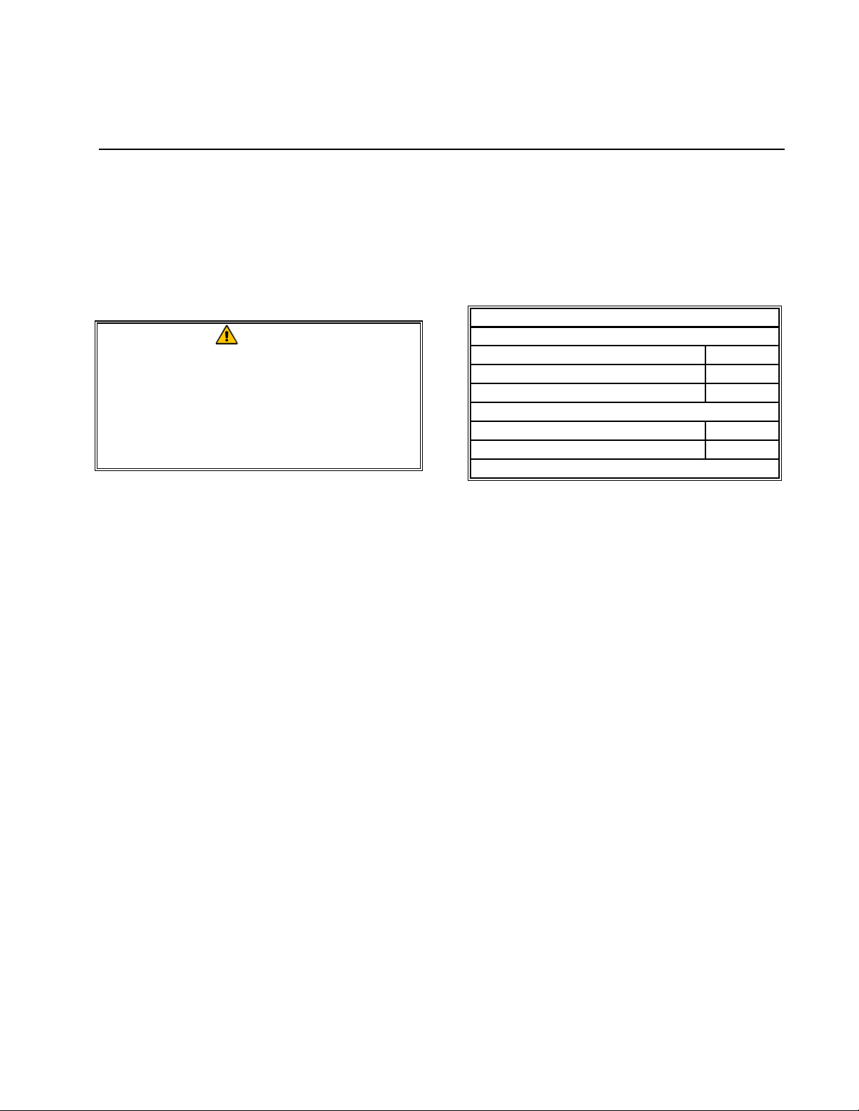
(FASC) technician. The table below identifies
the components required for conversion from
one gas to the other.
Gas Conversion Components
Natural to LP
Regulator Valve Spring, LP
Orifice, LP, 2.00mm
I
nitor
LP to Na tu r a l
Re
ulator Valve Spring, Natura l
Orifice, Natural, 3.26mm
nitor
I
810-1199
810-0917
810-0608
810-1198
810-0916
810-0521
2-5
Page 13
G18FB & G24FB SERIES GAS FRYERS
CHAPTER 3: OPERATING INSTRUCTIONS
3.1 Start-Up Procedure
CAUTION
If this is the first time the fryer is being
used after installation, refer to Section
3.2, Boil-Out Procedure.
CAUTION
The cooking oil/shortening capacity of
the G18FB fryer is 50 lbs (27 liters) at
70ºF (21ºC). The capacity of the G24FB
fryer is 64 lbs (36 liters) at 70ºF (21ºC).
Before lighting the fryer, make sure the
fryer is OFF and the frypot drain valve
is closed. Remove the basket support
rack, if installed, and fill the frypot to
the bottom OIL-LEVEL line.
If solid shortening is being used,
make sure it is packed down into the
bottom of the frypot.
2. For units equipped with Analog control-
lers, place the controller Power switch in
the ON position and set the temperature
knob to normal cooking temperature. For
units equipped with Computer Magic III
controllers, press the Power switch to the
ON position and program the computer for
normal cooking temperature.
3. If the burners fail to li ght, place the Power
switch in the OFF position and wait 60
seconds. Repeat step 2.
4. The fryer will automatically enter the Melt
Cycle mode if the frypot temperature is
below 180ºF (82ºC). (NOTE: During the
melt cycle, the burners will repeatedly fire
for a few seconds, then go out for a longer
period.) When the frypot temperature
reaches 180ºF (82ºC), the unit will automatically switch to the Heating mode. The
burners will remain lit until the frypot
temperature reaches the temperature set on
the thermostat or programmed into the
computer.
Lighting the Fryer
1. Place the controller Power switch in the
OFF position.
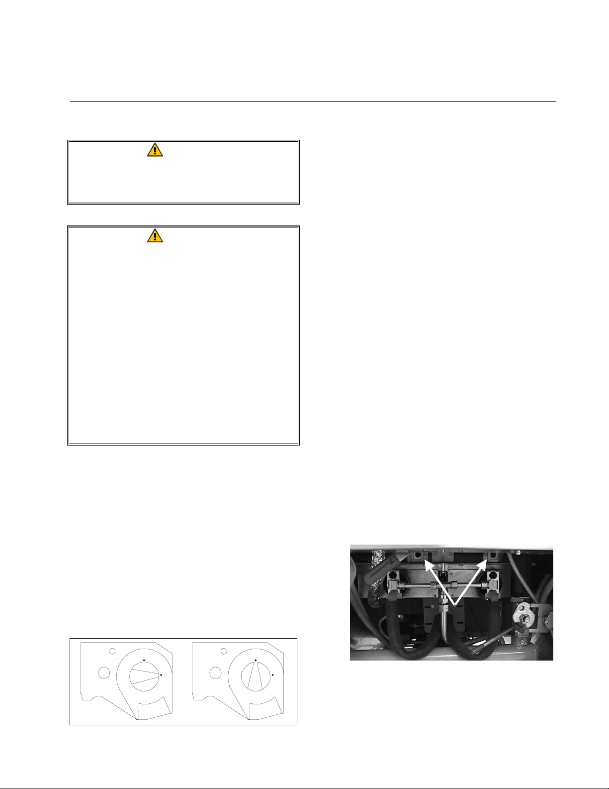
After placing the ON/OFF switch in the
OFF position, turn the gas valve knob to
the OFF position. Wait 5 minutes, then
turn the knob to the ON position.
ON
OFF
Honeywell
Honeywell
ON
OFF
5. After the burners have been lit for at least
90 seconds, observe the flames through the
burner viewports located above and to the
right side of each burner.
Viewports
The optimum burn is a bright orange-red
glow. If a blue flame is observed, or if
there are dark spots on a burner face, the
air/gas mix requires adjustment.
3-1
Page 14

G18FB & G24FB SERIES GAS FRYERS
CHAPTER 3: OPERATING INSTRUCTIONS
Air/Gas Mix Adjustment Procedure
On the side of the blower housing opposite the
motor is a round, sheetmetal plate with a single screw. Loosen the screw enough to allow
the plate to be moved, then adjust the position
of the plate to open or close the air intake
opening until a bright orange-red glow is obtained. Carefully hold the plate in position
and retighten the screw.
3.2 Boiling-Out the Frypot
DANGER
Never leave the fryer unattended
during the boil-out process. If the boil-
out solution boils over, turn off power
to the fryer immediately and let the
solution cool for a few minutes before
resuming the process.
4. Simmer the solution for 1 hour.
5. After the solution simmers for 1 hour, turn
the fryer off, allow the solution to cool,
then add 2 gallons (7.75 liters) of cold
water and stir. Drain the solution into a
suitable container and clean the frypot
thoroughly.
WARNING
Do not drain boil-out solution into the
built-in filtration system. Doing so may
cause damage to the filtration pump.
6. Rinse the frypot at least twice by filling the
frypot with clean water and draining. Dry
the frypot thoroughly with a clean, dry
towel.
To ensure that the frypot is free of any contamination resulting from its manufacture,
shipping, and handling during installation, the
frypot must be boiled out before first use.
Frymaster
Frymaster
FrymasterFrymaster
each time the oil or shortening is changed.
1. Before lighting the burners, close the fryer
drain valve and fill the frypot to the bottom OIL-LEVEL line with a mixture of
cold water and
GRIDDLE cleaner or detergent.
2. For units equipped with analog controllers,
set the thermostat to 200ºF (93ºC). For
units equipped with Computer Magic III
controllers, select the Boil-Out feature in
accordance with the procedure Using the
Boil-Out Feature on page 3-6.
3. Place the fryer into operation in accordance with Section 3.1.
recommends boiling out the frypot
Frymaster
Frymaster
FrymasterFrymaster
FRYER ‘N’
DANGER
Remove all drops of water from the
frypot before filling with cooking
oil/shortening. Failure to do so may
cause spattering of hot liquid when the
oil/shortening is heated to cooking
temperature.
3.3 Shutting the Fryer Down
For short-term shut down during the workday,
place the fryer power switch in the OFF position and put the frypot covers in place (if the
fryer is so equipped).
When shutting the fryers down at closing time,
place the controller power switch in the OFF
position, then place the gas valve knob in the
OFF position.
Put the frypot covers in place (if the fryer is so
equipped).
3-2
Page 15

G18FB & G24FB SERIES GAS FRYERS
N
CHAPTER 3: OPERATING INSTRUCTIONS
3.4 Controller Operation and
Programming
FPG18FB fryers are equipped with Computer
Magic III controllers.
1 234 5
OTE:
Some computers
may have this
earlier style
ON/OFF Switch:
ON
OFF
C Y C L
C Y C L
C Y C LC Y C L
Frym a s te r
L1 23445
All other models are equipped with solid-state
analog controllers.
Each type is discussed in detail in the following pages.
6
ON
OFF
COMPUTER MAGIC
78
C Y C L
C Y C L
C Y C LC Y C L
9
0R
ON
OFF
6 78
COMPUTER MAGIC III
COMPUTER MAGIC III CONTROLLER
The Computer Magic III control panel includes the following items:
1/2. Left and Right LED Displays
1/3. Temperature Check and Program Lock
Switch
4/5. Left and Right Frypot Power Switches
NOTE: Either switch will turn the fryer
on and off.
6/7. Left and Right Product Selection and
Coding Keys
1/8. Program Mode Switch
COMPUTER OPERATING INSTRUCTIONS
CAUTION
The electronic circuitry in your
computer can be affected adversely by
current fluctuations and electrical
storms. Should it fail to function or
program properly for no apparent
reason, the computer should be reset
by unplugging the computer and
plugging it back in. This could prevent
a service call.
Turn the computer on by pressing the Power
Switch (or ON/OFF Switch).
3-3
Page 16

G18FB & G24FB SERIES GAS FRYERS
CHAPTER 3: OPERATING INSTRUCTIONS
NOTE: A decimal between digits 1 and 2 in
either LED Display indicates that the burners
are on.
1. One of the following will be displayed:
a. cycl
cycl, indicating that the fryer is oper-
cyclcycl
ating in the melt cycle mode. The
fryer will remain in the melt cycle
mode until it reaches 180ºF (82ºC) or
is canceled manually by pressing the R
key.
CAUTION
Do not cancel the melt cycle mode
until solid shortening is completely
melted.
b. hi
hi, indicating that the frypot tempera-
hihi
ture is 21ºF (12ºC) higher than the setpoint.
c. LO
LO, indicating that the frypot tempera-
LOLO
ture is 21ºF (12ºC) lower than the setpoint.
ture display, the actual frypot temperature will be displayed.
2. Press a product switch to initiate a cook
cycle.
a. The display will indicate the previ-
ously programmed cook time and begin countdown.
b. If shake time is programmed, the op-
erator will be notified of the need to
shake the product “X” seconds after
the cook cycle has begun (X = amount
of time programmed). An alarm will
sound, and the display will read SH#
where “#” will be the switch number.
If no shake time has been programmed,
sh
sh#### will not appear during the cook
shsh
cycle. The alarm is self-canceling.
c. At the end of the cooking cycle, an
audible alarm will sound, cooc
displayed, and the associated product
switch indicator will flash. To cancel
the cook alarm, press the appropriate
switch.
cooc will be
cooccooc
SH#,
SH#SH#
d. “- - - -,” indicating that the frypot tem-
perature is in the cooking range.
NOTE: For best results, cooking
should not be attempted unless the display indicates “- - - -.”
e. help
help, indicating a heating problem.
helphelp
f. hot
hot, indicating the frypot temperature
hothot
is in excess of 410ºF (210ºC).
g. prob
prob, indicating that the computer has
probprob
detected a problem in the temperature
measuring and control circuits.
h. If the computer has been programmed
by the operator for constant tempera-
d. At this time, the hold time will be dis-
played (if programmed greater than
zero), and the countdown will begin.
When the countdown reaches zero,
hD_
hD_ will be displayed and an alarm
hD_hD_
will sound. The blank will be the
switch number. The hold alarm is canceled by pressing the Programming
Switch [
use, the hold time countdown will not
be displayed.
3. To check the frypot temperature at any
time, press the Temperature Check Switch
once. To check the setpoint, press the
switch twice. If you suspect that the
3-4
. NOTE: If the display is in
[
[[
Page 17

G18FB & G24FB SERIES GAS FRYERS
CHAPTER 3: OPERATING INSTRUCTIONS
temperature probe is defective, check the
temperature of the frypot with a
thermometer or pyrometer to verify that
the computer readout is reasonably close
to the measured reading.
4. During idle periods when the fryer is on
but not in use, “- - - -” should appear in
both displays. If not, check the actual
temperature and setpoint.
COMPUTER PROGRAMMING INSTRUCTIONS
1. Turn the computer on by pressing the
Power Switch (or ON/OFF
ON
OFF
Switch).
2. Enter the programming mode by pressing
the Program Mode Switch [[[[. Code
Code will
CodeCode
appear in the left display. If you enter the
programming mode by mistake, press the
switch again to exit the programming
mode. NOTE: If you try to enter the programming mode while the computer is
cooking, the display will flash busy
busy.
busybusy
3. Enter the number 1 6 5 0 by pressing the
number keys. Unless this code is entered,
programming will not be accepted. This is
to prevent unauthorized persons from
changing your current instructions.
4. sp-
sp-r (Setpoint) will appear in the left dis-
sp-sp-
play. Any previously programmed temperature setpoint will appear in the right
display. To change the setpoint, enter the
desired setpoint temperature using the
number keys. The highest setpoint allowed
is 375ºC (191ºC). Press the Program
Mode Switch [
to lock in the new setpoint
[
[[
(or the old setpoint, if it was not changed).
5. selp
selp (Select Product) will appear in the
selpselp
left display. Press the product button to be
programmed (or press to return to the
normal operating mode).
6. sens
sens (Sensitivity) appears in the left dis-
senssens
play. Any previously programmed sensitivity setting will appear in the right display. To change the sensitivity setting,
enter the new setting and press [
[
to lock it
[[
in. If the setting was not changed, pressing
[
[ accepts the previous setting.
[[
Sensitivity is a built-in feature that adjusts
cooking time to compensate for the drop in
frypot temperature when a basket of product is placed into it. Different food products will vary in density, basket load size,
and initial temperature. Food products
will also vary in how well cooked a product is required to be. A proper sensitivity
setting for each product will assure a
high-quality product each time. For example: four ounces of fries can be programmed to be cooked to the same quality
as two and one-half pounds. Some experimenting with the range of 0 - 9 (0 being least sensitive and 9 being most sensitive) may be required to obtain the desired
quality to meet your specifications, but
setting 5 is the recommended starting
point.
7. cooc
cooc (Cook Time) will now show in the
cooccooc
left display. Any previously programmed
cooking time will appear in the right dis-
play. Pressing [
will accept the current
[
[[
cooking time. To change the cooking
time, enter the new time using the Number
keys. Press [
8. sh_
sh_ (Shake Time) appears in the left dis-
sh_sh_
[
to lock in the new time.
[[
play. If your product requires shaking
during the cooking process, set the number
of seconds to cook before shaking using
the number keys.
3-5
Page 18

G18FB & G24FB SERIES GAS FRYERS
CHAPTER 3: OPERATING INSTRUCTIONS
For example, entering “30” means the
product needs to be shaken after it has
been cooking for 30 seconds. At the end
of one minute, an alarm will sound and the
product switch will flash for 3 seconds. If
your product does not require shaking,
enter “0”. The number entered will appear
in the right display. Press [[[[ to lock in the
programmed time.
9. hd_
hd_ (Hold Time) will appear in the left
hd_hd_
display. Set the time the product may be
held before serving, anything from 13 seconds to 60 minutes. If you do not wish to
use the hold time feature, enter 0. Press [
to lock in the time.
10. selp
selp (Select Product) will again appear in
selpselp
the left display. If more products are to be
programmed, return to Step 5 and follow
all instructions to this point, repeating for
each product.
11. When programming is completed, lock in
the whole program by pressing the Temperature Check/Program Lock Switch .
USING THE BOIL-OUT FEATURE
automatically set for 195ºF (91ºC). The
fryer will attain this temperature and
remain there until the Power (or
ON/OFF
ON
OFF
) Switch is pressed, which
cancels the boil-out mode. In high-altitude
locations, the fryer must be monitored
constantly for boil-over conditions. If
boil-over occurs, turn off the fryer
immediately, allow it to cool, then re-enter
the boil-out mode to continue the boil-out
process.
FRYER RECOVERY TIME CHECK FEATURE
[
[[
1. The computer automatically checks the
recovery time each time the frypot temperature drops below 250ºF (121ºC). To
check recovery time, press the Program
Mode Switch [[[[. Code
Code will appear in the
CodeCode
left display.
2. Enter the code number 1 6 5 2 on the number keypad. The recovery time will appear
in both displays for 5 seconds.
SELECTING FAHRENHEIT– CELSIUS DISPLAY
MODE
CAUTION
Before using this feature, ensure the
frypot is filled with a mixture of cold
water and
Frymaster
FRYER ‘N’
GRIDDLE cleaner or detergent.
1. To program the fryer for boil-out, press the
Power Switch (or ON/OFF
ON
OFF
Switch)
followed by the Program Mode Switch [[[[.
Code
Code will appear in the left display.
CodeCode
2. Enter the code number 1 6 5 3. The right
display will read boil
boil. The temperature is
boilboil
1. The comput er can display temperatures in
either Fahrenheit or Celsius. To change
from one to the other, press the Program
. Code
Mode Switch [
Code will appear in the
[
CodeCode
[[
left display.
2. Enter the code number 1 6 5 8 on the num-
ber keypad. The computer will toggle the
temperature display from Celsius to Fahrenheit or from Fahrenheit to Celsius.
3. Press the Temperature Check/Program
Lock Switch
to display the temperature
in the newly selected mode.
3-6
Page 19

G18FB & G24FB SERIES GAS FRYERS
CHAPTER 3: OPERATING INSTRUCTIONS
SELECTING FRYPOT TEMPERATURE DISPLAY
MODE
To display the actual frypot temperature at all
times, press the Program Mode Switch [[[[.
Code
Code will appear in the left display.
CodeCode
Power
Light
Frym as t e r
On
Heat
Mode
Light
Enter code 1 6 5 L in both number keypads.
The computer will display the actual frypot
temperature. NOTE: During the productcooking process, the cooking time will not
be displayed, but timing is taking place. To
return to setpoint display, repeat the process.
Melt
Trouble
Light
C
F
Cycle
Light
?
SOLID STATE
Power
Switch
ANALOG CONTROLLER
ANALOG CONTROLLER
T emperature
The analog controller uses a frypot-mounted
temperature probe and solid-state electronics
mounted on the control panel. The temperature probe is connected to the control circuitry
via an interface board behind the control
panel.
The cooking temperature is set by rotating the
Temperature Knob to the desired temperature.
When the Power Switch is placed in the ON
position, electrical current is supplied to the
fryer’s components and the Power On Light
illuminates. Placing the Melt Cycle Switch
Knob
Melt Cycle
Switch
in the ON position causes the burners to cycle
on for a few seconds and off for a longer period until the temperature in the frypot reaches
180ºF (82ºC). At that time the unit automatically enters the heat mode, causing the burners
to remain lit until the setpoint is reached.
When in the melt cycle, the Melt Cycle Light
will alternately illuminate and go out as the
burners cycle on and off. When the unit enters
the heat mode, the Heat Mode Light will
illuminate and remain on until the setpoint is
reached.
3-7
Page 20

G18FB & G24FB SERIES GAS FRYERS
CHAPTER 3: OPERATING INSTRUCTIONS
The Trouble Light will illuminate if there is an
ignition failure. To reset the controller after an
ignition failure, place the Power switch in the
OFF position for 30 seconds, then place it
back in the ON position. The Trouble Light is
also used to indicate the presence of a probe
circuit or high limit circuit problem.
3-8
Page 21

G18FB & G24FB SERIES GAS FRYERS
CHAPTER 4: FILTRATION INSTRUCTIONS
4.1 Draining and Manual Filtering
DANGER
Allow oil/shortening to cool to 100ºF
(38ºC) or lower before draining to an
appropriate container for disposal.
If your fryer is not equipped with a built-in
Filter Magic II or FootPrint III Filtration System, the cooking oil or shortening must be
drained into another suitable container. FOR
SAFE, CONVENIENT DRAINING AND DISPOSAL
OF USED COOKING OIL OR SHORTENING,
FRYMASTER
FRYMASTER
(SDU). THE SDU IS AVAILABLE THROUGH
YOUR LOCAL DISTRIBUTOR
Draining Fryers Other Than the FPG18FB
RECOMMENDS THE USE OF THE
SHORTENING DISPOSAL UNIT
.
1. Turn the fryer power switch to the OFF
position. Screw the drainpipe (provided
with your fryer) into the drain valve.
Make sure the drainpipe is firmly screwed
into the drain valve and that the opening is
pointing down.
DANGER
DO NOT insert anything into the drain
from the front to unclog the valve. Hot
oil/shortening will rush out, creating an
extreme hazard.
WARNING
DO NOT hammer on the drain valve
with the Fryer’s Friend. This will
damage the drain valve ball and
prevent the valve from sealing
securely, resulting in a leaky valve.
Draining the FPG18FB Fryer
The FPG18FB fryer is equipped with a quickdisconnect fitting for attaching a wand assembly, allowing the filter pump to be used to
transfer used oil to an oil disposal container.
1. Verify that the filter pan is positioned all
the way to the rear of the unit. The green
FILTER READY light will be illuminated
when the pan is properly positioned.
2. Position a metal container with a sealable
cover under the drainpipe. The metal
container must be able to withstand the
heat of the cooking oil/shortening and hold
hot liquids. If you intend to reuse the oil
or shortening, Frymaster recommends that
a Frymaster filter cone holder and filter
cone be used when a filter machine is not
available. If you are using a Frymaster
filter cone holder, be sure that the cone
holder rests securely on the container.
3. Open the drain valve slowly to avoid
splattering. If the drain valve becomes
clogged with food particles, use the
Fryer’s Friend (poker-like tool) to clear the
blockage.
2. Press the computer power switch to turn
the computer off. Slowly open the drain
valve, allowing the oil to drain into the
filter pan.
4-1
Page 22

G18FB & G24FB SERIES GAS FRYERS
CHAPTER 4: FILTRATION INSTRUCTIONS
If the drain valve becomes clogged with
food particles, use a stiff wire or thin rod
to clear the blockage.
DANGER
DO NOT insert anything into the drain
from the front to unclog the valve. Hot
oil/shortening will rush out, creating an
extreme hazard.
WARNING
DO NOT hammer on the drain valve.
This will damage the drain valve ball
and prevent the valve from sealing
securely, resulting in a leaky valve.
3. P ull back on the orange collar of the wand
assembly and position the hose-end fitting
onto the quick-disconnect fitting of the
fryer. Release the collar and pull firmly on
the hose near the collar to ensure that the
hose is securely attached.
5. Holding the wand handle firmly, with the
end inserted well into the disposal container, press the Dispose Wand switch to
the ON position.
The filter pump will energize, pumping oil
from the filter pan through the wand and
into the disposal unit.
6. When the filter pan has been emptied,
press the Dispose Wand switch to the OFF
position and move the Filter/Wand valve
handle to the OFF (center) position.
4. P lace the end of the wand i nto the di sposal
container and move the Filter/Wand valve
handle as far as it will go to the right.
7. Make sure the wand assembly is com-
pletely drained by lowering the discharge
end to a level below the quick-disconnect
fitting, allowing any remaining oil in the
hose to drain into a metal container.
When sure that no oil remains in the hose,
remove the hose by pulling back on the orange collar to release the hose from the
quick-disconnect fitting.
After Draining (All Models)
1. After draining, clean all food particles and
residual oil from the frypot. BE CAREFUL, this material may still cause severe
burns if it comes in contact with bare skin.
2. Close the drain valve securely and fill the
frypot with fresh cooking oil or solid
shortening to the bottom OIL-LEVEL line.
4-2
Page 23

G18FB & G24FB SERIES GAS FRYERS
CHAPTER 4: FILTRATION INSTRUCTIONS
DANGER
When using solid shortening, pack the
shortening down into the bottom of the
frypot. DO NOT operate the fryer with
a solid block of shortening sitting in
the middle of the frypot. This will
cause damage to the frypot and may
cause a flash fire.
4.2 Built-In Filtration System
Operation
Your fryer’s built-in filtration system allows
the cooking oil or shortening in one frypot to
be safely and efficiently filtered while the
other frypots in a battery remain in operation.
The majority of reported problems with the
built-in filtration system are found to be the
result of improper operation. Careful attention
to the step-by-step instructions that follow will
ensure that your system operates as intended.
PREPARING THE FILTER UNIT FOR USE
1. Slide the filter unit from the cabinet and
remove the filter pan lid, if so equipped.
2. Remove the crumb tray and paper holddown ring.
3. Ensure that the metal filter screen is in the
bottom of the pan.
4. Lay a sheet of filter paper over the top of
the filter pan, overlapping on all sides.
Position the hold-down ring over the filter
paper and lower the ring into the pan, allowing the paper to fold up around the ring
as it is pushed to the bottom of the pan.
4-3
Page 24

G18FB & G24FB SERIES GAS FRYERS
CHAPTER 4: FILTRATION INSTRUCTIONS
5. Sprinkle filter powder over the filter paper.
For powder quantity, see the filter powder
manufacturer’s instructions.
6. Replace the crumb tray in the filter pan. If
so equipped, replace the filter pan cover.
7. Roll the filter pan all the way to the back
of the cabinet. The HEATER ON light will
illuminate when properly positioned.
FPH150-half of FPH150-G18FB combination.
Handle shown in CLOSED position.
OPERATION OF THE FILTER UNIT
CAUTION
Never operate the filter unit unless the
cooking oil in the fryers has been
brought up to cooking temperature.
1. To filter the cooking oil, turn the fryer
power OFF, then open the drain valve on
the fryer you have selected to be filtered.
Use the Fryer's Friend steel rod to clear
the drain from inside the frypot if necessary. Drain valve locations will vary depending upon the particular configuration
of your equipment (i.e., FMG18FB or
FMG24FB, FPH150-G18FB combination,
or FPG18FB).
DANGER
Never drain more than one fryer at a
time—the filter pan may overflow.
When unclogging a valve, DO NOT
insert anything into the drain from the
front of the fryer. Hot oil will rush out,
creating an extreme hazard.
WARNING
DO NOT hammer on the drain valve
with the Fryer’s Friend. This will
damage the drain valve ball and
prevent the valve from sealing
securely, resulting in a leaky valve.
2. When the frypot is empty, use a fryer
scouring tool to remove sediment on the
sides of the frypot. Avoid striking the high
limit thermostat and temperature probe or
operating thermostat.
FMG18FB/FMG24FB, G18FB-half of
FPH150-G18FB combination, or FPG18FB.
andle shown in CLOSED position.
H
3. If so equipped, snap the Power Shower
into the frypot.
DANGER
On FMG18FB/FMG24FB units, and on
FPH150-G18FB units with Power
Shower selected, DO NOT operate
the filter without the Power Shower
in place. Hot oil will spray out of
the fryer and may cause injury.
4-4
Page 25

G18FB & G24FB SERIES GAS FRYERS
CHAPTER 4: FILTRATION INSTRUCTIONS
4. After all oil has drained from the pot, po-
sition the filter control to start the pump
and begin the filtering process. There may
be a slight delay before the pump activates. Control operation will vary depending upon the particular configuration
of your equipment (i.e., FMG18FB or
FMG24FB, FPH150-G18FB combination,
or FPG18FB).
Filter Control ON.
FMG18FB/FMG24FB or G18FB-half of
FPH150-G18FB combination.
The FPG18FB does not have a Power
Shower. It is, however, equipped with a
quick-disconnect fitting for attaching a
wand assembly. This configuration allows
the filter pump to be used to transfer used
oil to an oil disposal container or recovery
system. The wand assembly is not designed or intended for use as a substitute
for a Power Shower or rear flush system.
WARNING
The dispose wand and filter should not
be operated simultaneously.
5. After the oil is completely filtered, close
the drain valve and allow the fryer to refill.
Allow the filter to run 10 to 12 seconds
after bubbles appear in the oil to clear the
lines and prevent hardening of shortening
in the lines.
Filter Control with
Power Shower
selected.
FPH150-half of
FPH150-G18FB combination.
FPG18FB
WARNING
The filter pump motor is equipped with
a manual reset switch, located at the
left rear of the motor housing, in case
the filter motor overheats or an
electrical fault occurs. If this switch
trips, turn off power to the filter system
and allow the pump motor to cool
40 minutes before attempting to reset
the switch.
6. When the fryer is full, position the Filter
Control to the OFF position. If used, remove the Power Shower and allow it to
drain.
7. Make sure the drain valve is fully closed.
Turn the fryer ON and allow the cooking
oil/shortening to reach setpoint.
NOTE: Ensure the fryer drain valve is fully
closed before turning the fryer on. If the drain
valve is not fully closed, the fryer will not operate.
4-5
Page 26

G18FB & G24FB SERIES GAS FRYERS
CHAPTER 4: FILTRATION INSTRUCTIONS
CHANGING THE FILTER PAPER
DANGER
Allow the filter pan to cool completely
before attempting to change the paper.
1. Slide the filter unit from the cabinet. If so
equipped, remove the filter pan lid. Remove and clean the crumb tray.
2. Remove the hold-down ring from the filter
pan and clean.
4. Remove the metal filter screen and clean
thoroughly using a solution of hot water
and detergent. Allow the screen to dry
completely before reinstalling. Clean all
breading and food particles from the filter
pan, then replace the filter screen in the
bottom of the pan.
CAUTION
Make sure the inside of the pan is free
of all food and breading particles that
could prevent the paper from sealing
against the bottom of the pan.
3. Remove and discard the used filter paper.
5. Lay a sheet of filter paper over the top of
the filter pan with the paper overlapping
on all sides. Position the hold-down ring
over the filter paper on top of the pan and
lower the ring into the pan, allowing the
filter paper to fold up around the ring as it
is pushed to the bottom of the pan.
4-6
Page 27

G18FB & G24FB SERIES GAS FRYERS
CHAPTER 4: FILTRATION INSTRUCTIONS
6. Sprinkle filter powder over the filter paper.
For powder quantity and instructions, see
the powder manufacturer's instructions.
7. Replace the crumb tray in the filter pan
and, if so equipped, replace the filter pan
cover.
8. Roll the filter pan all the way to the back
of the cabinet. The
HEATER ON light will
illuminate when properly positioned.
4-7
Page 28

G18FB & G24FB SERIES GAS FRYERS
CHAPTER 5: PREVENTIVE MAINTENANCE
5.1 Fryer Preventive Maintenance
Checks and Services
DAILY CHECKS AND SERVICES
Inspect Fryer and Accessories for Damage
Look for loose or frayed wires and cords,
leaks, foreign material in frypot or inside
cabinet, and any other indications that the
fryer and accessories are not ready and safe for
operation.
Clean Fryer Cabinet Inside and Out
Clean inside the fryer cabinet with dry, clean
cloth. Wipe all accessible metal surfaces and
components to remove accumulations of oil or
shortening and dust.
Clean the outside of the fryer cabinet with a
clean, damp cloth soaked with dishwashing
detergent, removing oil/shortening, dust, and
lint from the fryer cabinet.
WEEKLY CHECKS AND SERVICES
Drain and Clean Frypot
During normal usage of your fryer, a deposit
of carbonized cooking oil or shortening will
gradually form on the inside of the frypot.
This deposit must be periodically removed to
maintain your fryer’s efficiency.
If your fryer is not equipped with a built-in
filtration system, the cooking oil or shortening
must be drained into another suitable container. (For safe, convenient draining and
disposal of used cooking oil or shortening,
Frymaster recommends using our Shortening
Disposal Unit (SDU). The SDU is available
through your local distributor.)
1. Place the fryer power switch in the OFF
position. Screw the drainpipe (provided
with your fryer) into the drain valve.
Make sure the drainpipe is firmly screwed
into the drain valve and that the opening is
pointing down.
DANGER
Never attempt to clean fryer during the
cooking process or when the frypot is
filled with hot oil/shortening. If water
comes in contact with oil/shortening
heated to cooking temperature, it can
cause the oil/shortening to splatter and
severely burn nearby personnel.
Filter Cooking Oil/Shortening
Filter cooking oil/shortening in accordance
with the instructions in Chapter 4 at least once
daily, just before the fryer is shut down for the
day. Additional filtering may be required
during the day depending upon amount and
type of product being fried.
2. Position a metal container with a sealable
cover under the drainpipe. The metal
container must be able to withstand the
heat of the cooking oil/shortening and hold
hot liquids. If you intend to reuse the oil
or shortening, Frymaster recommends that
our filter cone holder and filter cone be
used when a filter machine is not available. If you are using a Frymaster filter
cone holder, be sure that the cone holder
rests securely on the metal container.
3. Open the drain valve slowly to avoid
splattering. If the drain valve becomes
clogged with food particles, use the
Fryer’s Friend (poker-like tool) to clear the
blockage.
5-1
Page 29

G18FB & G24FB SERIES GAS FRYERS
CHAPTER 5: PREVENTIVE MAINTENANCE
DANGER
DO NOT insert the tool into the drain
from the front to unclog the valve. Hot
oil/shortening will rush out, creating an
extreme hazard.
WARNING
DO NOT hammer on the drain valve.
This will damage the drain valve ball
and prevent the valve from sealing
securely, resulting in a leaky valve.
4. After draining the oil/shortening, clean all
food particles and residual oil/shortening
from the frypot. BE CAREFUL, this material may still cause severe burns if it
comes in contact with bare skin.
5. Close the drain valve securely and fill the
frypot with a solution of detergent and
water to the bottom OIL-LEVEL line.
(Frymaster recommends the use of
Frymaster Boilout Solution, available
through your local distributor, for best
results.)
9. Drain the solution into a suitable container
(NOT the built-in filtration system filter
pan or the Shortening Disposal Unit)
and thoroughly wipe the frypot with a
clean towel.
10. Close the drain valve and fill the frypot
with clean, cold water and drain. Repeat
the rinse process again, and then wipe frypot with a clean, dry towel.
DANGER
Ensure that the frypot is completely
free of water before filling with cooking
oil or shortening. When the oil or
shortening is heated to cooking
temperature, water in the frypot will
cause splattering.
Clean Detachable Parts and Accessories
As with the frypot, a deposit of carbonized
oil/shortening will accumulate on detachable
parts and accessories such as baskets, sediment trays, or fish plates
6. Set the thermostat to 200ºF (93ºC) or program the computer for Boil Operation as
outlined in the Section 3.2, Computer
Magic III Operation and Programming.
7. Simmer the solution for 1 hour.
WARNING
Never leave the fryer unattended
during this process. If the solution
overflows, press the ON/OFF switch to
the OFF position immediately.
8. After the solution has simmered for 1
hour, press the ON/OFF switch to the OFF
position and allow the solution to cool.
Wipe all detachable parts and accessories with
a clean cloth dampened with a detergent solution. (Frymaster recommends the use of
Frymaster
Fryer ‘N’ Griddle Cleaner, available
through your local distributor, for best results.)
Rinse and thoroughly dry each part.
MONTHLY CHECKS AND SERVICES
Check Calibration of Analog Controller
Thermostat Control Knob
(This check applies only to units equipped
with Analog Controllers)
5-2
Page 30

G18FB & G24FB SERIES GAS FRYERS
CHAPTER 5: PREVENTIVE MAINTENANCE
1. Insert a good-grade thermometer or py-
rometer probe into the oil/shortening, with
the end touching the fryer temperaturesensing probe.
2. Set the thermostat knob to frying tem-
perature.
3. After t he set temp erature i s reached, let th e
burner cycle on and off automatically three
times to allow the cooking oil/shortening
temperature to become uniform. If necessary, stir to get all shortening in the bottom
of the frypot melted.
4. When the burner starts for the fourth time,
the thermometer/pyrometer reading should
be within ± 5ºF (2ºC) of the thermostat
knob setting. If it is not, calibrate as follows:
a. Loosen setscrew in thermostat control
knob until the knob will rotate freely
on its shaft.
5. Remove the thermometer or pyrometer.
Check Computer Magic III Set Point
Accuracy
(This check applies only to units equipped
with Computer Magic III Controllers.)
1. Insert a good-grade thermometer or py-
rometer probe into the oil/shortening, with
the end touching the fryer temperaturesensing probe.
2. W hen the computer display shows a series
of four dashes “----” with no dot between
the first and second dashes (indicating that
the frypot contents are within the cooking
range), press the switch once to display
the temperature of the cooking oil or
shortening as sensed by the temperature
probe.
3. Press the switch twice to display the set
point.
b. Rotate the knob until the index line on
the knob is aligned with the marking
that corresponds to the thermometer or
pyrometer reading.
c. Hold the knob and carefully tighten the
setscrew.
d. Recheck the thermometer/pyrometer
reading against the thermostat knob
setting the next time the burner lights.
e. Repeat steps 4.a. through 4.d. until the
thermometer/pyrometer reading and
knob setting agree within ± 5ºF (2ºC).
If calibration cannot be obtained for
any reason, call a Factory Authorized
Service Center for assistance.
4. Note the temperature on the thermometer
or pyrometer. All three readings should be
within ± 5ºF (2ºC) of each other. If not,
contact a Factory Authorized Service
Center for assistance.
QUARTERLY CHECKS AND SERVICES
Clean Combustion Air Blower Assembly
The blowers in your fryer will vary depending
upon the configuration of your fryer. G18FB
and G24FB units, FMG18FB and FMG24FB
units, the G18FB-half of FPH150-G18FB
combination units, and FPG18FB units all
have one type of blower. The FPH150-half of
FPH150-G18FB combination units has a
5-3
Page 31

G18FB & G24FB SERIES GAS FRYERS
CHAPTER 5: PREVENTIVE MAINTENANCE
different blower type. Each type is discussed
in following paragraphs.
FPH150 Blower Cleaning Procedure
1. Disconnect the blower wiring harness and
remove the blower assembly mounting
nuts.
Blower
assembly
mounting
nuts
Wiring
connection
2. R emove the three lock nuts t hat secure the
blower motor assembly to the blower
housing, and separate the two components.
Remove
these nuts
Note:
Silver-colored
Kooltronics
blowers will
have three
screws instead
of three nuts.
3. Wrap the motor with plastic wrap to
prevent water from entering it. Spray
degreaser or detergent on the blower wheel
and the blower housing. Allow to soak for
five minutes. Rinse the wheel and housing
with hot tap water, then dry with a clean
cloth.
Blower Wheel
Wrap motor with
plastic wrap
4. Remove the plastic wrap from the blower
motor assembly. Reassemble the blower
motor assembly and blower housing.
Reinstall blower assembly on fryer.
5. Light the fryer in accordance with the
procedure described in Chapter 3, Section
3.1.
6. After the burners have been lit for at least
90 seconds, observe the flames through the
burner viewing ports located on each side
of the combustion air blower.
5-4
Left
Viewing
Port
Right
Viewing
Port
Behind
Motor
Page 32

G18FB & G24FB SERIES GAS FRYERS
CHAPTER 5: PREVENTIVE MAINTENANCE
The air/gas mixture is properly adjusted
when the burner manifold pressure is in
accordance with the applicable table on
page 5-7 and the burners display a bright
orange-red glow. If a blue flame is observed, or if there are dark spots on a
burner face, the air/gas mix requires adjustment.
On the side of the blower housing opposite
the motor is a plate with one or two
locking nuts. Loosen the nut(s) enough to
allow the plate to be moved, then adjust
the position of the plate to open or close
the air intake opening until a bright
orange-red glow is obtained. Carefully
hold the plate in position and tighten the
locking nut(s).
Remove this screw.
3. Using a χ-inch allen wrench, loosen the 2
setscrews securing the blower wheel to the
shaft.
Cleaning Procedure for All Other Blowers
1. Remove the 3 hex-head bolts from the
blower mounting bracket. (For FPG18FB
units, slide the filter pan out of the unit
and move out of the way before removing
the bolts.)
Upper bolts are behind shield.
Lower bolt.
2. Lower the blower assembly and rotate it so
that the plate covering the side is facing
you. Remove the screw securing the plate
to the motor housing.
Setscrews
4. Pull the blower wheel out of the housing
and clean with a detergent solution or nontoxic degreaser. Rinse and dry the wheel
thoroughly.
5. S lip the blower wheel back onto the shaft,
ensuring that one of the setscrews aligns
with the flat surface of the shaft before
tightening them. Spin the wheel and adjust its position as necessary to ensure that
it does not rub the housing.
6. Tighten the setscrews snugly, replace the
cover plate, and remount the blower assembly to its bracket.
5-5
Page 33

G18FB & G24FB SERIES GAS FRYERS
p
CHAPTER 5: PREVENTIVE MAINTENANCE
7. Light the fryer in accordance with the
procedure described in Chapter 3, Section
3.1.
8. After the burners have been lit for at least
90 seconds, observe the flames through the
burner viewing ports.
The air/gas mixture is properly adjusted
when the burner manifold gas pressure is
in accordance with the accompanying table
and the burners display a bright orange-red
glow. If a blue flame is observed, or if
there are dark spots on a burner face, the
air/gas mix requires adjustment.
Loosen the blower cover plate screw
enough to allow the plate to be moved,
then adjust the position of the plate to
open or close the air intake opening until a
bright orange-red glow is obtained. Carefully hold the plate in position and
retighten the screw.
3. Pass a piece of ordinary binding wire (.052
inch diameter) through the tube to remove
any obstruction.
4. Remove the wire and blow through the
tube to ensure it is clear.
5. Reinstall tube and bend so that the opening
is pointing downward.
Check Burner Manifold Pressure
WARNING
Frymaster recommends that this task
be performed by qualified service
personnel only.
1. Ensure that the gas valve knob is in the
OFF position.
2. Remove the pressure tap plug from the gas
valve assembly.
SEMI-ANNUAL CHECKS AND
SERVICES
Clean Gas Valve Vent Tube
1. Set the fryer power switch and the gas
valve to the OFF position.
2. Carefully unscrew the vent tube from the
gas valve. NOTE: The vent tube may be
straightened for ease in removal.
Pressure
Tap Plug
Regulator Ca
Vent Tube
3. Insert the fitting for a gas pressure-
measuring device into the pressure tap.
4. Place the gas valve in the ON position, and
then place the controller power switch in
the ON position. When the burner lights
and continues to burn, note the gas
pressure reading for correct pressure in
accordance with the table below.
Burner Manifold Gas Pressures
Gas Pressure
Natural
LP
3" W.C.
0.73 kPa
8.25" W.C.
2.5 kPa
5. To adjust burner gas pressure, remove the
cap from the gas valve regulator and adjust
to the correct pressure.
5-6
Page 34

G18FB & G24FB SERIES GAS FRYERS
CHAPTER 5: PREVENTIVE MAINTENANCE
6. Place the fryer power switch and the gas
valve in the OFF position. Remove the
fitting from the pressure tap hole and
reinstall the pressure tap plug.
5.2 Built-in Filtration System
Preventive Maintenance Checks
and Services
WARNING
Never operate the filter system without
cooking oil/shortening in the system.
WARNING
Never use the filter pan to transport old
cooking oil/shortening to the disposal
area.
WARNING
Never drain water into the filter pan.
Water will damage the filter pump.
screen is on the bottom of the filter pan, with
the paper on top of the screen. Verify that the
o-ring(s) are present and in good condition.
There is an o-ring on the bottom of the pan
and two on the fitting at the inside back of the
cabinet.
Immediately after each use, drain the Power
Shower completely. If you suspect blockage,
unscrew the clean-out plugs at each corner of
the frame. Place the frame in a pan of hot
water for several minutes to melt any
accumulation of solidified oil/shortening. Use
a long, narrow bottlebrush with hot water and
detergent to clean inside the tubes. If
necessary, insert a straightened paper clip or
similarly sized wire into the holes in the frame
to remove any solidified shortening or other
blockages. Rinse with hot water, dry
thoroughly, and reinstall the plugs before
using.
There are no periodic preventive maintenance
checks and services required for your built-in
filtration system other than daily cleaning of
the filter pan and its components with a solution of hot water and detergent.
If you notice that the system is pumping
slowly or not at all, verify that the filter pan
DANGER
Failure to reinstall the clean-out plugs
will cause hot oil/shortening to spray
out of the frypot during the filtering
process, creating an extreme burn
hazard to personnel.
5-7
Page 35

G18FB & G24FB SERIES GAS FRYERS
CHAPTER 6: OPERATOR TROUBLESHOOTING
6.1 Introduction
This chapter provides an easy reference guide
to the more common problems that may occur
during the operation of your equipment. The
troubleshooting guides in this chapter are
intended to help you correct, or at least
accurately diagnose, problems with your
equipment. Although the chapter covers the
most common problems reported, you may
very well encounter a problem not covered. In
such instances, the Frymaster Technical
Service Department will make every effort to
help you identify and resolve the problem.
When troubleshooting a problem, always use a
process of elimination starting with the
simplest solution and working through to the
most complex. Never overlook the obvious.
Anyone can forget to plug a cord into a
receptacle or put a piece of filter paper into a
filter pan. Don’t assume that you are exempt
from such occurrences.
Most importantly, always try to establish a
clear idea of why a problem has occurred.
Part of your corrective action involves taking
steps to ensure that it doesn’t happen again. If
a controller malfunctions because of a poor
connection, check all other connections while
you’re at it. If a fuse continues to blow, find
out why. Always keep in mind that failure of
a small component may often be indicative of
potential failure or incorrect functioning of a
more important component or system.
Several of the corrective actions recommended
in this chapter involve removing a suspect
controller from the system and substituting
one that is known to be good. Whenever this
in indicated, refer to Section 6.4 for specific
instructions.
Each guide begins with a description of a
common problem in a six-sided figure.
Simply follow the arrows and answer the
questions to determine the corrective action to
take.
If you are in doubt as to the proper action to
take, do not hesitate to call the Frymaster
Technical Service Department or your local
Frymaster Factory Authorized Service Center
for assistance.
DANGER
Hot cooking oil or shortening causes
severe burns. Never attempt to move a
fryer containing hot cooking
oil/shortening or to transfer hot
cooking oil/shortening from one
container to another.
DANGER
Use extreme care when performing
electrical circuit tests. Live circuits
will be exposed.
WARNING
Inspection, testing, and repair of
electrical equipment should be
performed only by qualified service
personnel. The equipment should be
unplugged when servicing, except
when electrical tests are required.
6-1
Page 36

G18FB & G24FB SERIES GAS FRYERS
CHAPTER 6: OPERATOR TROUBLESHOOTING
6.2 Troubleshooting Fryers and Controllers
BURNER(S)
WON'T LIGHT.
Verify unit is plugged into a
Are any
control panel lights
illuminated?
Yes
live circuit with main circuit
No
breaker in ON position.
Press ON/OFF switch OFF,
then back ON.
Verify gas valve(s) is/are
in ON position and that
main gas supply valve is
open. If unit is equipped
with built-in filtration
system, verify drain
valve(s) is/are fully
closed. Press ON/OFF
switch OFF, then back
ON.
Did
burner(s) light?
No
Yes
No
burner(s) light?
Did
Yes
Problem
resolved.
Press ON/OFF switch
OFF. Disconnect gas
line quick-disconnect
fitting and reconnect.
Press power switch
ON, wait 30 seconds,
turn power switch OFF.
Repeat 3 more times to
purge air from gas line.
Yes
Did
burner(s) light?
6-2
No
Problem is beyond
scope of operator
troubleshooting. Call FASC or
Frymaster Service
Department.
Page 37

G18FB & G24FB SERIES GAS FRYERS
CHAPTER 6: OPERATOR TROUBLESHOOTING
Troubleshooting Fryers and Controllers
CANNOT
CONTROL FRYPOT
TEMPERATURE
ACCURATELY.
What are the
symptoms?
ANALOG CONTROLLER
POWER LIGHT AND
TROUBLE LIGHT ON, BUT
NO HEAT LIGHT or CM III
SHOWS "PROB" IN DISPLAY
UNIT STAYS IN MELT
CYCLE (BURNER ON
FOR 6 SECONDS AND
OFF FOR 24 SECONDS
CONTINUOUSLY)
Is displayed
temperature above 180
degrees F (82
degrees C)?
Yes
Problem is
failed controller. Order
replacement from
FASC.
If condition persists for more
than 45 minutes, call FASC or
No
Frymaster Service
Department.
Problem
resolved.
Turn unit OFF and disconnect
from electrical power. Replace
controller with another known to
be working. Reconnect unit to
electrical power. Turn unit ON.
Does fryer
Yes No
operate properly?
CM III DISPLAYS "oHI"
AS IT COMES OUT OF
MELT CYCLE or HEATING
MODE INDICATOR DOES
NOT COME ON AT ALL
Re-enter
setpoint.
Does fryer
Yes
operate properly?
No
Problem is beyond
scope of operator
troubleshooting. Call FASC or
Frymaster Service
Department.
HEATING MODE
INDICATOR ON, BUT
FRYER NOT HEATING
PROPERLY
Yes
Does
burner come on
at all?
No
Refer to
Troubleshooting Guide
BURNER DOES NOT
LIGHT.
6-3
Page 38

G18FB & G24FB SERIES GAS FRYERS
CHAPTER 6: OPERATOR TROUBLESHOOTING
Troubleshooting Fryers and Controllers
CM III WILL NOT GO
INTO PROGRAMMING
MODE (DISPLAY IS
NOT BLANK).
Turn unit OFF. Disconnect unit from
electrical power. Open control panel
and disconnect 15-pin plug from back
of computer. Wait one minute.
Reconnect 15-pin plug and close
control panel. Press power switch ON.
Will computer
go into programming
mode?
No
Turn unit OFF. Disconnect unit from
electrical power, open control panel,
remove computer and replace with
another known to be working. Close
control panel. Reconnect unit to
electrical power. Turn unit ON.
Does
computer operate
properly?
No
Problem is beyond
scope of operator
troubleshooting.
Yes
Yes
Verify setpoint and
product settings are correct.
Re-enter settings if
necessary.
Problem is a
defective computer.
Order replacement
from FASC.
Call FASC or Frymaster
Service Department.
6-4
Page 39

G18FB & G24FB SERIES GAS FRYERS
CHAPTER 6: OPERATOR TROUBLESHOOTING
6.3 Troubleshooting the Built-in Filtration System
PUMP WON'T
START.
Verify that filter power
cord is plugged in and
that circuit breaker on.
Probable cause is failed filter
Does pump start
if a different filter control
is activated?
No
Yes
control microswitch (or on FPG18FB, filter
control rocker switch). On FPH150-G18FB
combination units, verify actuating cam is tight
on shaft before replacing switch. Call
FASC Frymaster Service
Department.
PUMP
STOPPED DURING
FILTERING PROCESS AND
WON'T RESTART.
Is pump motor hot (cannot
hold hand on pump)?
Yes
Allow motor to cool for at least 45
minutes then press thermal
overload switch reset button and
move filter control to ON position.
Did pump
start and continue
to run?
Yes
Problem
resolved.
No
PUMP WON'T
What happened?
No
Move filter handle to OFF position.
Allow oil/shortening to cool, then
empty pan and verify that filter paper
and screen have been properly
installed and are clean. Refill pan and
move filter control to ON posistion.
Yes No Yes
Did pump
start and continue
to run?
START AFTER BEING
OFF FOR AT LEAST
ONE HOUR.
Press thermal overload
switch reset button and
move filter control to ON
Did pump
No Yes
start and continue
Did pump
start and then abrubtly
position.
to run?
stop?
No
Problem
resolved.
Reset thermal overload
switch. Remove filter
pan and move control to
ON position.
Probable causes are a
failed 24-volt transformer or
a defective motor. Call FASC
or Frymaster Service
Department.
Is filter
wiring harness properly
connected at both ends and free of
cuts, breaks, or other signs of
damage?
No
If filter harness is properly
connected but is damaged,
probable cause is failed wiring
harness. Order replacement from
FASC or call Frymaster
Service Department.
Did motor hum
NoYes
for a short time and then
stop?
Yes
Probable cause is a
pump blockage. Pump blockages
are usually caused by sediment build-up
in the pump due to improperly sized or
installed filter paper. Call FASC or
Frymaster Service Department.
6-5
Does pump
No
run okay?
Yes
Probable cause is a
blockage of the filter pan suction
tube. Remove blockage using a thin,
flexible wire and attempt to operate filter.
If unable to remove blockage, call
FASC or Frymaster Service
Department.
Page 40

G18FB & G24FB SERIES GAS FRYERS
CHAPTER 6: OPERATOR TROUBLESHOOTING
Troubleshooting the Built-in Filtration System
PUMP STARTS, BUT
NO TRANSFER TAKES
PLACE OR TRANSFER
IS VERY SLOW.
Move filter control to
Is pumping erratic
No
(spitting/spurting)?
Yes
Move filter control to OFF position. Allow
oil/shortening to cool, then empty pan. For Filter
Magic and FootPrint II units, verify that o-ring on
pan outlet is present and in good condition. Verify
that the o-ring on the oil return fitting at the inside
rear of the cabinet is present and in good
condition. Verify that filter paper and screen have
been properly installed and are clean. Refill the
filter pan and move filter control to the ON position.
OFF position. Remove
filter pan. Move filter
control to ON position.
Probable cause is
improperly
installed/prepared filter
pan components.
Yes
strong stream of
air being pumped out of
Power Shower
Is
port?
No
Problem
resolved.
Is
Yes
oil/shortening
being returned to
frypot?
No
Probable cause is solidified
oil/shortening in the filtration unit
return lines. Move filter control to
the OFF position, wait 10 minutes,
then move filter control to ON
position.
Is
Yes
oil/shortening
being returned to
frypot?
No
Probable causes are solidified oil/shortening in
filtration unit return lines or blockage of return line
suction tube on bottom of filter pan. A blockage of
the return line suction tube is usually due to
sediment/food particle build-up caused by failure
to use crumb tray and the use of improperly sized
or installed filter paper. Failure of solidified
oil/shortening in the return lines to melt indicates a
defective heater tape or 24 volt transformer.
If unable to clear
blockages, call
FASC.
6-6
Page 41

G18FB & G24FB SERIES GAS FRYERS
CHAPTER 6: OPERATOR TROUBLESHOOTING
Troubleshooting the Built-in Filtration System
POWER SHOWER
NOT SPRAYING
PROPERLY.
How much oil is
coming out of the
Power Shower?
Little or none, but
it is squirting out
around gasket.
Probable causes are power
shower holes plugged with
debris or solidified
oil/shortening in the Power
Shower tubing.
Move the filter control to the
OFF position and remove the
unit from the frypot. Remove
the clean-out screws and
place the unit in a pan of hot
water for several minutes to
melt the oil/shortening. Insert
a straightened paper clip or
similarly sized wire into each
hole to clear any blockages.
Replace and tighten clean-out
screws. Reinstall Power
Shower, ensuring that it seats
properly in its receptacle.
Move the filter control to the
ON position.
Little or none, and
nothing is squirting
out around gasket.
Oil/shortening is not reaching
the Power Shower. Ensure that the
Power Shower receptacle in the frypot
is not obstrutcted. If it is clear, refer to
the Trouble Shooting Guide
on page 6-6.
Plenty, but it is
also squirting out
around gasket.
Probable causes are
missing/worn o-rings and
gasket on Power Shower or
no filter paper in the filter pan
(causing too much pressure).
Replace o-rings and
gasket or install filter
paper, whichever is
appropriate.
Is the Power
Shower spraying
properly?
No
Yes
Problem
resolved.
Problem is beyond
scope of operator
troubleshooting. Call FASC or
Frymaster Service
Department.
6-7
Yes
Is Power
Shower spraying
properly?
No
Page 42

G18FB & G24FB SERIES GAS FRYERS
CHAPTER 6: OPERATOR TROUBLESHOOTING
Troubleshooting the Built-in Filtration System
AFTER FILTERING, FRYER
DOES NOT OPERATE PROPERLY.
ANALOG CONTROLLER TROUBLE
LIGHT ON or CM III COMPUTER
DISPLAY SHOWS "HELP".
Verify that drain
valve is fully
closed.
Is fryer operating
Refer to Troubleshooting
Guides in Section 6.2.
6.4 Replacing the Controller
1. Disconnect the fryer from the electrical
supply.
2. Remove the two screws in the upper
corners of the control panel and swing the
panel open from the top, allowing it to rest
on its hinge tabs.
properly?
No
Yes
Problem
resolved.
3. Disconnect the wiring harness from the
back of the controller.
4. Remove the controller by lifting it from
the hinge slots in the control panel frame.
5. Reverse the procedure to install a new
controller.
6-8
 Loading...