

Page 1
PRO H50/55-SERIES GAS FRYERS
CHAPTER 2: PARTS LIST
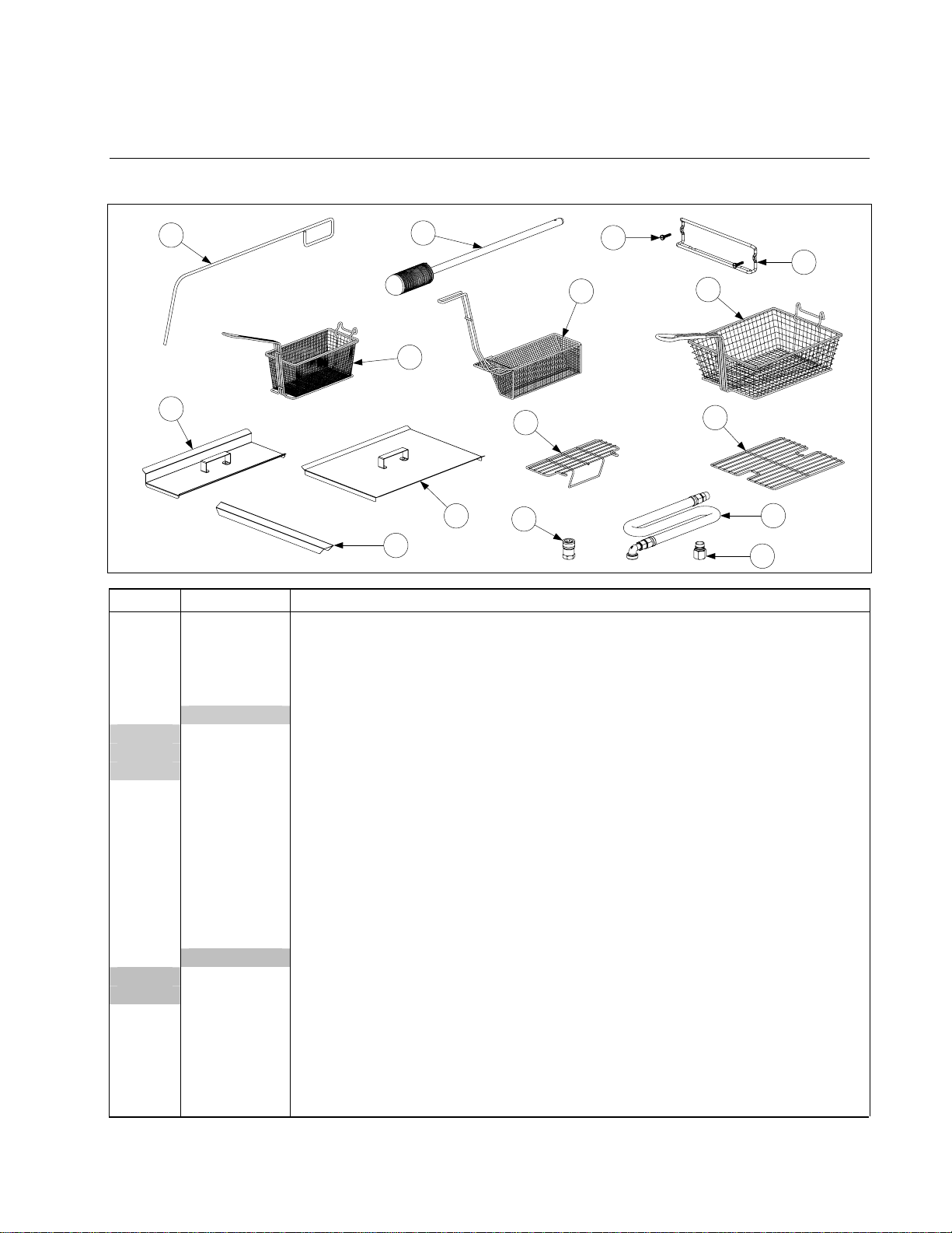
2.1 Accessories
6
8
ITEM PART # COMPONENT
1 803-0271 Basket, Twin
2 803-0099 Basket, Full (cannot be used with basket lifts)
3 803-0133 Basket Support Rack, Dual Vat
4 803-0132 Basket Support Rack, Full Vat
* 803-0136 Basket Support Screen, Full Vat (screen w/handle used in place of Item 4)
5 Sediment Screens
803-0103 Full Vat
803-0107 Dual Vat, Left
803-0108 Dual Vat, Right
6 803-0197 Cleanout Rod, 27-inch (Fryer's Friend)
7 803-0209 Brush, Frypot
8 806-3232 Cover, Frypot, Dual Vat
9 806-5518 Cover, Frypot, Full Vat
* 826-0993SP Handle Kit, Frypot Cover (includes handle and screws)
10 910-7443 Top Connecting Strip, Frypot
* 823-1885 Top Connecting Strip, Frypot, Burger King
* 910-6650 Channel, Top Connecting Strip
* 910-5126 Channel, Top Connecting Strip, Burger King
11 Gas Line, 1-Inch Dormont Flexible (includes Items 12 and 13)
806-1698SP 36-Inch (for gas line only [w/o Items 12 and 13], use 810-0088)
806-1699 42-Inch (for gas line only [w/o Items 12 and 13], use 810-0085)
12 810-0074 Quick-Disconnect Fitting, 1-Inch Male
13 810-0073 Quick-Disconnect Fitting, 1-Inch Female
14 810-2793 Hanger, Basket
15 809-0171 Thumbscrew, 1/4-20 X 1 3/8-inch Basket Hanger (for spacer use 809-0921)
* 803-0170 Filter Paper - 100 Sheets
* 803-0002 Powder, Filter – 80 Packages
* Not illustrated.
7
1
3
9
10
13
15
5
2
4
14
11
12
PDF compression, OCR, web optimization using a watermarked evaluation copy of CVISION PDFCompressor
2-1
Page 2
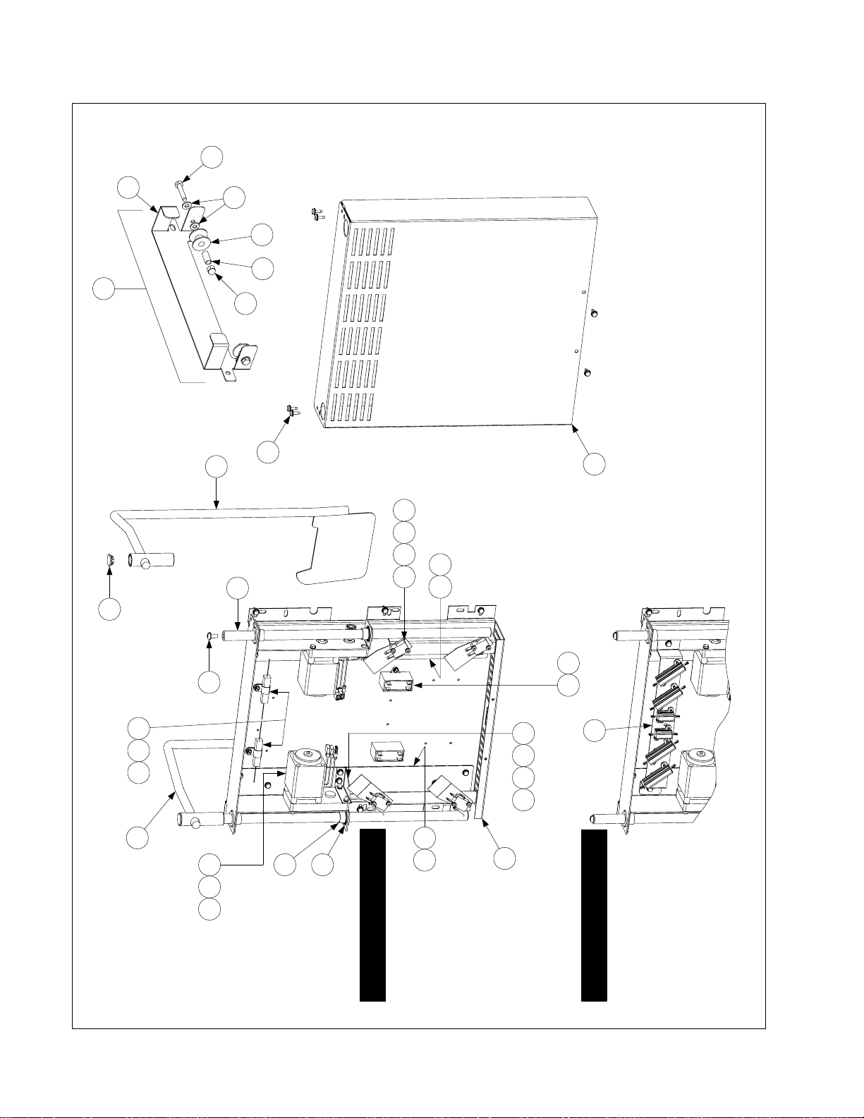
2.2 Basket Lift Assemblies and Component Parts
31
28
27
16
32
29
30
33
14
25
4 10 12 18
17
14 22
24
NOTES:
1. Assemblies 106-1807SP (100-120V) and 106-1810SP (208-250V) do not
include Items 8, 16, or 24-33. These items must be ordered separately.
2. For 100-120V units, each individual resistor (807-2661) may be replaced or
the entire reistor assembly (806-8530SP) may be replaced.
3. For 208-250V units, the entire resistor assembly (106-2771) must
be replaced.
4. Wiring has been omitted for clarity.
8
20135
26
6
1592
19
2314
2114117
1
100-120V Configuration
3 13
5
208-250V Configuration
PDF compression, OCR, web optimization using a watermarked evaluation copy of CVISION PDFCompressor
2-2
Page 3

ITEM PART # COMPONENT
1 200-2942 Mount, Modular Basket Lift
2 806-5964SP Motor Assembly, Modular Basket Lift
3 807-2133
4 807-2572 Microswitch
5 Resistor Assembly
806-8530SP
106-2771 208-250V Modular Basket Lift
6 809-0082 Ring, Truarc Retaining
7 826-1361 Screw, 2-32 X 1-inch Slotted Truss Head (pkg. of 25)
8 809-0127 Screw, 1/4-20 X 1/2-inch Slotted Round Head
9 809-0186 Lock Washer w/External Teeth, #8
10 826-1366 Nut, 4-40 Hex Keps (pkg. of 25)
11 809-0247 Nut, 2-32 Hex Keps
12 826-1359 Screw, 4-40 X 3/4-inch Slotted Round Head (pkg. of 25)
13 826-1371 Screw, #8 X 1/2-inch Hex Head Drill Point (pkg. of 25)
14 826-1374 Screw, #10 X 1/2-inch Hex Head (pkg. of 25)
15 809-0503 Screw, 2-32 X 1/2-inch Hex Head
16 810-0172
17 810-1012 Rod, Modular Basket Lift
18 812-0442 Insulation, Microswitch
19 813-0035 Bushing, Bronze, .640” ID
20 816-0033 Tie Wrap, Screw Mount
21 900-5529 Gusset, Modular Basket Lift Motor
22 901-8499 Chassis, Modular Basket Lift, Left
23 902-8499 Chassis, Modular Basket Lift, Right
24 910-4776 Cover, S/S Modular Basket Lift (for CRS cover use 900-4776)
25 823-06931 Rod Assembly, Left Basket Lift
26 823-06932 Rod Assembly, Right Basket Lift
27 806-9257SP Roller Assembly, Basket Lift
28 910-8284 Bracket, Basket Lift Roller
29 810-0194 Roller, Basket Lift
30 810-0374 Spacer, Basket Lift Roller
31 809-0508 Bolt, 1/4-20 X 11/4-inch
32 809-0190 Washer, ¼-inch Flat
33 809-0047 Nut, 1/4-20 Cap
* 807-0159 Connector, 12-Pin Panel Mount
* 106-1822SP For 100-120V Modular Basket Lift
* 106-1804SP For 208-250V Modular Basket Lift
* 106-1807SP 100-120V w/o Relay
* 106-1810SP 208-250V w/o Relay
** Not illustrated.
Capacitor, 12.5 μFarad, 250VAC Motor Run
100-120V Modular Basket Lift (see Note 2 in illustration)
5/8-
Plug,
Wire Assemblies
Basket Lift Assemblies (see Note 1 in illustration)
inch Stainless Steel Hole
PDF compression, OCR, web optimization using a watermarked evaluation copy of CVISION PDFCompressor
2-3
Page 4
2.3 Cabinetry
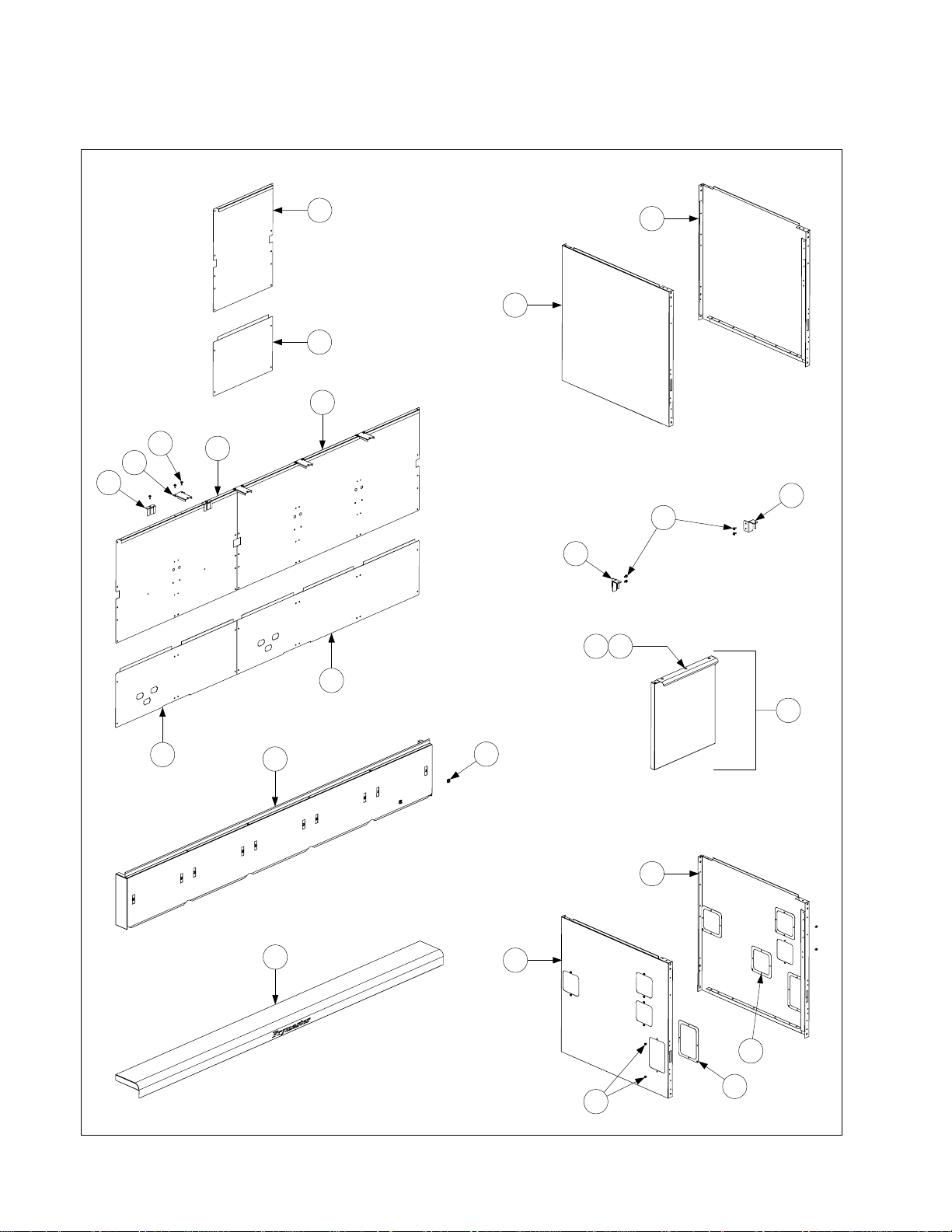
2.3.1 Backs, Doors, Flue Caps, Sides, and Top Caps
1
17
2
5
9
8
7
3
13
18
14
8
1211
6
10
4
15
24
16
20
19
22
21
23
PDF compression, OCR, web optimization using a watermarked evaluation copy of CVISION PDFCompressor
2-4
Page 5

r
r
)
)
)
)
t
p
)
r
r
r
g
)
y
)
y
)
y
)
y
)
)
t
t
t
t
)
f
f
f
f
f
ITEM PART # COMPONENT
1 Back, Single Uppe
210-6581 Stainless Steel
200-6581 Cold Rolled Steel
2 Back, Single Lowe
210-6580 Stainless Steel
200-6580 Cold Rolled Steel
3 Back, Double Upper (for 2-, 4-, and 5-station fryers – does not include Items 7-9
210-6542 Stainless Steel
200-6540 Cold Rolled Steel
4 Back, Double Lower (for 2-, 4-, and 5-station fryers – does not include Items 7-9
210-6541 Stainless Steel
200-6539 Cold Rolled Steel
5 Back, Triple Upper (for 3- and 5-station fryers – does not include Items 7-9
210-6545 Stainless Steel
200-6547 Cold Rolled Steel
6 Back, Triple Lower (for 3- and 5-station fryers – does not include Items 7-9
210-6544 Stainless Steel
200-6546 Cold Rolled Steel
7 200-6419 Clip, Flue Suppor
8 200-5865 Support, Flue Ca
9 826-1374 Screw, #10 X 1/2-inch Hex Washer Head (pkg. of 25
10 106-3966 Door, Left or Right (Left shown – move handle to bottom for Right)
11 809-0266 Screw, #10 X 1/2-inch Phillips Truss Head
12 210-6820 Handle, Doo
13 823-4729 Hinge, Left Door Uppe
14 823-4730 Hinge, Right Door Uppe
15 Flue Cap (Cap for 5-station fryer shown – does not include Item 16)
210-5549
106-3579
106-3537
106-3535
106-3536
le Fryer (use 823-4367 for BK w/Buttons
Sin
2-Station Fr
3-Station Fr
4-Station Fr
5-Station Fr
er (use 106-3545 for BK w/Buttons
er (use 106-3546 for BK w/Buttons
er (use 106-3547 for BK w/Buttons
er (use 106-3548 for BK w/Buttons
16 826-1351 Nut Retainer, 1/4-20 (pkg. of 10 – receives basket hanger thumbscrew
17 Side, Left Standard Cabine
211-6510 Stainless Steel
201-6633 Enameled Steel
18 Side, Right Standard Cabine
212-6510 Stainless Steel
202-6633 Enameled Steel
19 Side, Left Filter Ready Cabine
211-6660 Stainless Steel
201-6660 Enameled Steel
20 Side, Right Filter Ready Cabine
212-6660 Stainless Steel
202-6660 Enameled Steel
21 910-0890 Cover, 5-inch X 7-inch Access
22 910-0889 Cover, 5-inch X 5-inch Access
23 809-0359 Screw, #8 X ¼-inch Hex Washer Head
24 Top Cap (Cap 5-station fryer shown
824-1310 Single Fryer (use 824-1689
824-1357 2-Station Fryer (use 824-1690
823-4702 3-Station Fryer (use 823-5733
823-4704 4-Station Fryer (use 824-5734
823-4706 5-Station Fryer (use 824-5735
or fryers mfd. After 3.15.06)
or fryers mfd. After 3.15.06)
or fryers mfd. After 3.15.06)
or fryers mfd. After 3.15.06)
or fryers mfd. After 3.15.06)
PDF compression, OCR, web optimization using a watermarked evaluation copy of CVISION PDFCompressor
2-5
Page 6
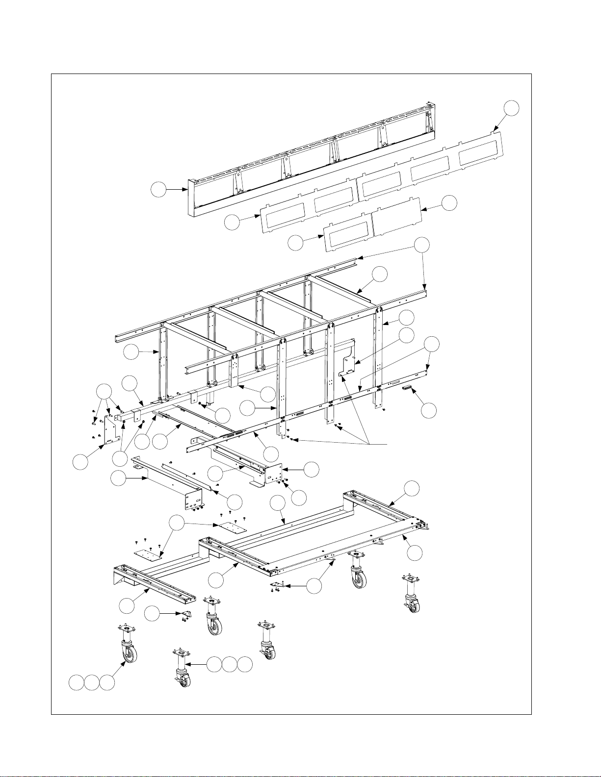
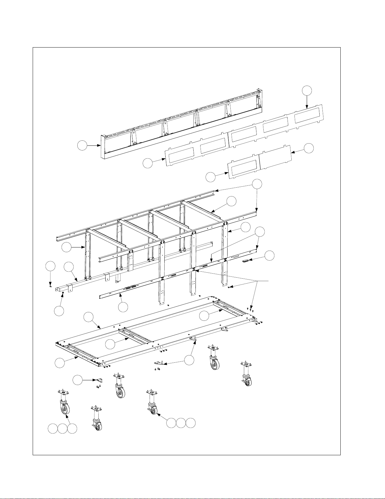
2.3.2 Filter Cabinet Bases, Casters, Framing, and Related Components
The 5-station cabinet illustrated is typical
of all Pro Series (H50/55) gas filter
cabinets. All base and framing
components used in Pro Series (H50/55)
gas filter cabinets are identified, but not all
components are used in every
configuration.
1
2
3
5
4
7
11
15
31
34
10
9
6
8
19
12
14
All cabinet screws, unless otherwise
17
16
18
34
20
24
23
22
13
21
31
27
indicated, are #10 x 1/2-inch Hex
Washer Head P/N 826-1374, sold in
packages of 25.
25
26
25
25
28
See Page 2-4 for upper hinges.
29
NOTE: 2- and 3-station
fryers have 4 casters; 4- and
5-station fryers have 6.
30 32 33
333231
PDF compression, OCR, web optimization using a watermarked evaluation copy of CVISION PDFCompressor
2-6
Page 7

ITEM PART # COMPONENT
1 Frame, Control Panel
106-3902SP
106-3903SP
106-3904SP
106-3905
Two-Station, Standard
Three-Station, Standard
Four-Station, Standard
Five-Station, Standard
(use 106-5221SP mfd. After 3.15.06)(use 106-6082 for fallback)
(use 106-5018SP mfd. After 3.15.06)(use 106-6086 for fallback)
(use 106-5019 mfd. After 3.15.06) (use 106-6087 for fallback)
(use 106-5020 mfd. After 3.15.06) (use 106-6089 for fallback)
2 210-5819 Bezel, Two-Controller
3 210-6698 Bezel, Three-Controller
4 210-5046 Bezel, One-Controller
5 210-5623 Bezel, Blank
6 Brace, Cabinet Top
900-7730 Two-Station
900-9430 Three-Station
900-9318 Four-Station
200-5474 Five-Station
7 200-5478 Divider, Cabinet
8 200-6614 Post, Cabinet Front
9 200-6031 Post, Filter Door
10 200-2235 Bracket, Component Box Support
11 200-6550 Post, Cabinet Rear
12 200-1953 Brace, Front Cabinet
13 200-6507 Support, Cross Cabinet
14 810-1105 Magnet, Door
15 Manifold, Rear
823-3223 Two-Station
823-4691 Three-Station
823-4693 Four-Station
823-4694 Five-Station
16 200-2213 Bracket, Rear Bridge Support
17 200-0913 Bridge, Filter Pump
18 200-6326 Gusset, Left Rear Corner
19 200-7031 Gusset, Right Rear Corner
20 201-6508 Support, Left Filter Rail
21 202-6508 Support, Right Filter Rail
22 823-4651 Slide, Filter Pan Lid Left
23 823-4652 Slide, Filter Pan Lid Right
24 200-2102 Brace, Side Channel
25 823-4653 Channel, Side Base
26 Channel, Front Base (not used in two-station fryers)
200-6609 Three-Station
200-6610 Four-Station
200-5473 Five-Station
27 Channel, Rear Base
823-4510 Two-Station
823-4630 Three-Station
823-4629 Four-Station
823-4628 Five-Station
28 823-4732 Hinge, Lower Left
29 823-4733
Hinge, Lower Right (attach to hinge bracket 200-5478 in 4- & 5-station fryers)
30 810-0944 Caster w/Brake, 8 1/2 to 10-inch Adjustable (3-inch wheel)
31 810-0327 Caster w/o Brake, 8 1/2 to 10-inch Adjustable (4-inch wheel)
32 809-0953 Bolt, 1/4-20 x 3/4-inch Hex Head
33 809-0191 Washer, 1/4-inch Lock
34 809-0417 Nut, 1/4-20 Flange
* 810-1494 Caster w/o Brake, 4-inch Swivel
* 810-0326 Caster w/Brake, 4-inch Adjustable
* Not illustrated.
PDF compression, OCR, web optimization using a watermarked evaluation copy of CVISION PDFCompressor
2-7
Page 8
2.3.3 Non-Filter Cabinet Bases, Casters, Framing, and Related Components
The 5-station cabinet illustrated is typical of
all Pro Series (H50/55) gas non-filter
cabinets. All base and framing components
used in Pro Series (H50/55) gas non-filter
cabinets are identified, but not all
components are used in every configuration.
3
1
2
2
6
7
8
11
10
13
22
14
All cabinet screws, unless
5
otherwise indicated, are #10
x 1/2-inch Hex Washer
Head P/N 826-1374, sold in
packages of 25.
24
17
12
15
15
15
18
See Page 2-4 for upper hinges.
19
NOTE: 2- and 3-station
fryers have 4 casters; 4- and
5-station fryers have 6.
232221
20 22 23
PDF compression, OCR, web optimization using a watermarked evaluation copy of CVISION PDFCompressor
2-8
Page 9

ITEM PART # COMPONENT
1 Frame, Control Panel
806-4732 Single-Station, Standard (use 106-5016 mfd. After 3.15.06) (use 106-6079 for fallback)
106-3902SP Two-Station, Standard (use 106-5221SP mfd. After 3.15.06)(use 106-6082 for fallback)
106-3903SP Three-Station, Standard (use 106-55018SP mfd. After 3.15.06)(use 106-6086 for fallback)
106-3904SP Four-Station, Standard (use 106-5019 mfd. After 3.15.06)(use 106-6087 for fallback)
106-3905 Five-Station, Standard (use 106-5020 mfd. After 3.15.06)(use 106-6089 for fallback)
2 210-5819 Bezel, Two-Controller
3 210-6698 Bezel, Three-Controller
4 210-5046 Bezel, One-Controller
5 210-5623 Bezel, Blank
6 Brace, Cabinet Top
200-5498 Single Fryer
900-7730 Two-Station
900-9430 Three-Station
900-9318 Four-Station
200-5474 Five-Station
7 200-5478 Divider, Cabinet
8 200-6614 Post, Cabinet Front
9 200-2235 Bracket, Component Box Support
10 200-6550 Post, Cabinet Rear
11 200-1953 Brace, Front Cabinet
12 200-6507 Support, Cross Cabinet
13 810-1105 Magnet, Door
14 Manifold, Rear (not present in single fryers)
823-3223 Two-Station
823-4691 Three-Station
823-4693 Four-Station
823-4694 Five-Station
15 823-4653 Channel, Side Base
16 Channel, Front Base
200-6616
200-6623
200-6624
Single Fryer (also used as rear base channel in single-station fryers)
Two-Station (also used as rear base channel in single-station fryers)
Three-Station (also used as rear base channel in single-station fryers)
200-6625 Four-Station
200-6627 Five-Station
17 Channel, Rear Base
200-6626 Four-Station
200-6628 Five-Station
18 823-4732 Hinge, Lower Left
19 823-4733
Hinge, Lower Right (attach to bracket 200-5478 in 3-, 4-, & 5-station fryers)
20 810-0944 Caster w/Brake, 8 1/2 to 10-inch Adjustable (3-inch wheel)
21 810-0327 Caster w/o Brake, 8 1/2 to 10-inch Adjustable (4-inch wheel)
22 809-0953 Bolt, 1/4-20 x 3/4-inch Hex Head
23 809-0191 Washer, 1/4-inch Lock
24 809-0417 Nut, 1/4-20 Flange
PDF compression, OCR, web optimization using a watermarked evaluation copy of CVISION PDFCompressor
2-9
Page 10
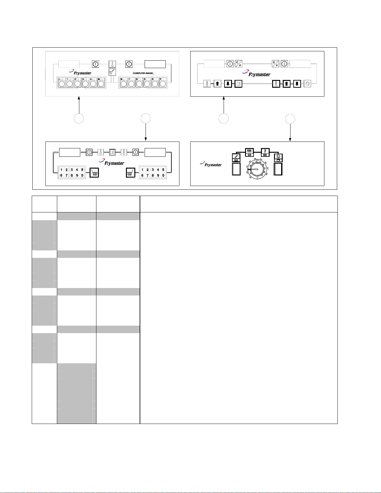
2.4 Controllers
1 2 3
ITEM *Standard
PART #
*Euro-Look
PART #
COMPONENT
4
SOLID STATE
1 Computer Magic III.5
106-1151SP 106-3446 Dual-vat (Domestic U.S.)
106-1187SP 106-3447 Dual-vat (CE) (use 106-3450 for 8-second MC Non-CE export units)
106-1150SP 106-3445 Full-vat (Domestic U.S.)
106-1188SP 106-3448 Full-vat (CE) (use 106-3449 for 8-second MC Non-CE export units)
2 Basket Lift Timer
106-2074SP 106-3580 Dual-vat (Domestic U.S.)
106-2081SP 106-3496 Dual-vat (CE) (use 106-3497 for 8-second MC Non-CE export units)
106-2073SP 106-3504 Full-vat (Domestic U.S.)
106-2080SP 106-3495 Full-vat (CE) (use 106-3498 for 8-second MC Non-CE export units)
3 Digital Controller
106-1510 106-3492 Dual-vat (Domestic U.S.)
106-1506 106-3494 Dual-vat (CE) (use 106-3499 for 8-second MC Non-CE export units)
106-1509SP 106-3503 Full-vat (Domestic U.S.)
106-1505SP 106-3493 Full-vat (CE) (use 106-3500 for 8-second MC Non-CE export units)
4 Solid State (Analog) Controller (controller knob is 810-0387)
806-3008 106-3375 Dual-vat (Domestic U.S.) (use 106-3398 for Foodmaker units)
806-3564 106-3572 Dual-vat (Non-CE Export) (not available for CE Units)
806-3006E 106-3369 Full-vat (Domestic U.S.) (use 106-3364 for Foodmaker units)
806-3563 106-3501 Full-vat (Non-CE Export) (not available for CE Units)
* 806-4323 Fallback Controller Assembly, Dual-vat
* 806-9224 Fallback Controller Assembly, Full-vat
* 210-5623 Blank Panel (for fryers with remote mounted computers)
* 806-2071 15-pin Wiring Harness, Computer-to-Interface Board
* 106-1226 Remote Computer, Burger King
* 806-3528 Internal Cable, 7 1/2-feet
* 806-3531 Internal Cable, 12 1/2-feet
* 806-3388 External Cable, 20-feet
* Not illustrated.
* Pro H50/55-Series cabinets were manufactured with standard cabinets with the 90º-edge topcap
and the Euro-Look cabinets with the rounded topcap. The Euro-Look cabinets also have a separate
bezel. The computers that fit the appropriate cabinet are not interchangeable.
PDF compression, OCR, web optimization using a watermarked evaluation copy of CVISION PDFCompressor
2-10
Page 11
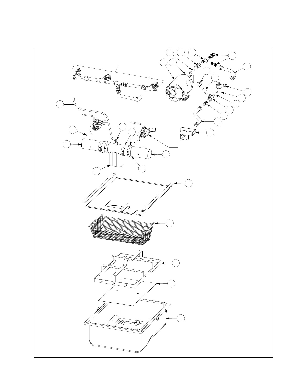
2.5 Drain, Filtration, and Oil Return System Components
2.5.1 Filtration System Components
22
24
26
27
See Page 2-16
12
8
11
10
21
15
20
24
25
19
18
17
16
15
14
13
7
6
9
See Page 2-14
7
5
4
3
2
1
PDF compression, OCR, web optimization using a watermarked evaluation copy of CVISION PDFCompressor
2-11
Page 12

ITEM PART # COMPONENT
1 826-1981 Pan Assembly, FootPrint Pro Filter (includes 826-1980 and Items 2 and 3)
826-1980 Pan Assembly, Filter (includes Plug, O-rings, Rollers, and Nuts)
813-0568 Plug, 1/8-inch NPT Socket Head
816-0012 O-Ring (two required)
810-2198
809-0059
Roller, Filter Pan (See NOTE at bottom of page.)
Nut, 1/4-20 Hex Flange (See NOTE at bottom of page.)
2 200-2124 Screen, Sana Grid
3 810-2091 Ring, Filter Paper Hold-Down Ring (13.47-inch X 21.41-inch)
4 823-5146 Tray, Filter Pan Crumb
5 823-4662 Lid, Filter Pan
6 Tube, 3-inch Center Drain
823-4678 Open Both Ends
823-4708 Closed One End
7 Tube, 3-inch Round Drain (823-4625 illustrated)
823-4638 Dual Vat, Long (one end closed)
823-4640 Dual Vat, Long (open both ends)
823-4624 Dual Vat, Short (one end closed)
823-4642 Dual Vat, Short (open both ends)
823-4639 Full Vat, Long (one end closed)
823-4641 Full Vat, Long (open both ends)
823-4625 Full Vat, Short (one end closed)
823-4643 Full Vat, Short (open both ends)
200-6473 Spreader, Long (open both ends, no drain valve connection)
200-6474 Spreader, Short (open both ends, no drain valve connection)
8 809-0247 Nut, 8-32 Hex Keps
9 816-0625 Sleeve, Round Drain Connector
10 809-0969 Clamp, Round Drain Sleeve
11 810-2493 Elbow, 1/4-inch NPT X 90° Tube Compression
12 811-1071 Tube, 1/4-inch OD Teflon Manifold Vent
13 823-3879 Suction Tube, FootPrint Pro Female
14 810-1055 Flexline, 5/8-inch OD X 11.50-inch
15 810-1668 Adapter, 5/8-inch OD X 1/2-inch Male
16 813-0530 Tee, 1/2-inch X 1/2-inch X 1/4-inch Reducing
17 813-0838 Nipple, 1/4-inch NPT Close
18 106-3470 Solenoid Valve w/Female Pins
19 810-2773 Adapter, 1/4-inch NPT to 1/2-inch NPT
20 810-1067 Flexline, 5/8-inch OD X 8.50-inch
21 813-0165 Elbow, 1/2-inch NPT X 90° Street
22 813-0003 Tee, 1/2-inch NPT
23 813-0265 Nipple, 1/2-inch NPT X 2.50-inch
24 813-0342 Elbow, 1/2-inch NPT X 45° Street
25 813-0298 Nipple, 1/2-inch NPT X 2.00-inch
26 826-1264 Pump and Gasket Kit (for gasket only, order P/N 816-0093)
27 Motor and Gasket Kit, 50/60 Hz (for gasket only, order P/N 816-0093)
826-1785 100V
826-1712 115V
826-1756 208V
826-1757 220-240V
826-1755 250V
* 106-0675 Plumbing Assembly (used with rear flush, page 2-19)
NOTE: Kit 826-1979 contains four each of roller 810-2198 and 1/4-20 Flange Nut 809-0059.
PDF compression, OCR, web optimization using a watermarked evaluation copy of CVISION PDFCompressor
2-12
Page 13
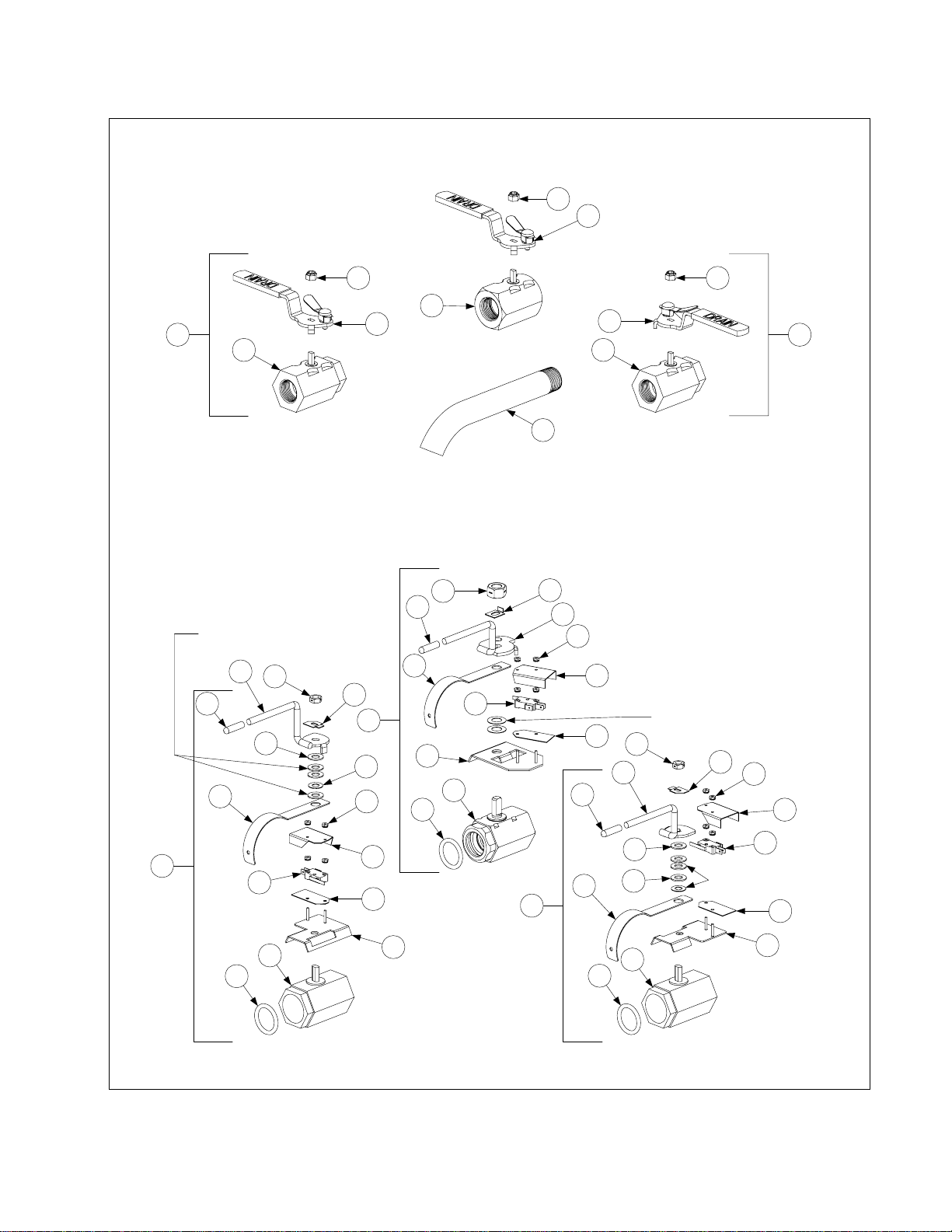
2.5.2 Drain Valves and Associated Components
Non-Filter Drain Valve Assemblies
4 4
1
2 3
34 34
6
Full-vat
4
5
7
Compression washers
and flat washer are
components of Item 23.
21
22
9
Dual-vat Left Dual-vat Right
35
FootPrint and Filter Magic Drain Valve Assemblies
20
21
28
27
26
24
25
17
15
22
15
8
13
12
11
30
Full-vat
14
19
18
17
16
14
29
21
22
10
Compression washers are
components of Item 12.
27
26
24
Compression washers
25
and flat washer are
components of Item 23.
17
31
15
14
23
11
32
23
11
33
Dual-vat Left Dual-vat Right
PDF compression, OCR, web optimization using a watermarked evaluation copy of CVISION PDFCompressor
2-13
Page 14

ITEM PART # COMPONENT
1 810-1569 Valve Assembly, 1.25-inch Full-vat Non-Filter Drain (includes handle)
2 806-7915SP Valve Assembly, 1-inch Left Dual-vat Non-Filter Drain (complete assembly)
3 806-7916SP Valve Assembly, 1-inch Right Dual-vat Non-Filter Drain (complete assembly)
4 809-0589 Nut, 1/2-13 2-Way Lock (used on non-filter drain valves)
5 810-1427 Handle w/Lock Pin, Full-vat
6 810-1568 Handle w/Lock Pin, Left Drain Valve, Dual-vat
7 810-1567 Handle w/Lock Pin, Right Drain Valve, Dual-vat
8 106-1106SP Valve Assembly, 1.25-inch Full-vat w/Filter Drain (complete assembly)
9 106-3513SP Valve Assembly, 1-inch Left Dual-vat w/Filter Drain (complete assembly)
10 106-3512SP Valve Assembly, 1-inch Right Dual-vat w/Filter Drain (complete assembly)
11 816-0135 O-Ring, Drain Valve
12 810-1018 Valve, 1.25-inch Drain
13 806-8137 Bracket Assembly, Drain Safety Switch
14 816-0220 Insulation, Drain Safety Switch
15 807-2103 Microswitch, Lever Activated
16 200-5694 Cover, Full-vat Drain Safety Switch
17 809-0237 Nut, 4-40 Hex Keps
18 823-4606 Handle, Full-vat Drain Valve
19 900-2936 Retainer, Full-vat Drain Valve Nut
20 809-0540 Nut, 1/2-13 2-Way Lock
21 816-0677 Grip, Drain Valve Handle
22 200-6496 Support, 3-inch Drain Tube
23 810-1114 Valve, 1-inch Dual-vat w/Filter Drain
24 809-0196 Washer, 3/8-inch Flat
25 810-1165 Washer, 3/8-inch Teflon
26 900-2934 Retainer, Dual-vat Drain Valve Nut
27 809-0539 Nut, 3/8-16 2-Way Lock
28 823-4577 Handle, Left Dual-vat Drain Valve
29 823-4578 Handle, Right Dual-vat Drain Valve
30 901-2348 Cover, Left Dual-vat Drain Safety Switch
31 902-2348 Cover, Right Dual-vat Drain Safety Switch
32 106-2671 Bracket Assembly, Left Dual-vat Drain Safety Switch
33 106-2672 Bracket Assembly, Right Dual-vat Drain Safety Switch
34 810-1338 Valve, 1-Inch Dual-vat Non-Filter Drain
35 Drain Valve Extension
812-1226SP Full-vat, 1.25-inch
812-1227 Dual-vat, 1-inch
PDF compression, OCR, web optimization using a watermarked evaluation copy of CVISION PDFCompressor
2-14
Page 15

2.5.3 Oil Return Line Components
36
17
18
31
2 11 12
There are more than 160 oil return line
combinations. The three examples shown
are typical. These examples identify all of
the components used in the various con-
figurations, but not all of the components
identified are used in every configuration
or in only the position shown.
18
12
11
2
35
36
2 11 12
15
2 10 12
35
15
2 11 12
2 10 12
FV)
36
38
30
33
18
35
3
23
34
29
15
21
26
4
6
7
36
32
25
2
5
Detail of Item 3
9
8
16
10
12
19
14
31
38
29
2 11 12
13
2 10 12
1
Vat)
FPPH550/555 (FV, FV, DV, FV,
FMPH250/255 (Dual-Vat, Spreader, Dual-
20
15
22 38
28
24
17
38
31
2 11 12
1
13
38
32
37
27
16
FV with Oil Disposal System)
FPPH550/555 (FV, FV, DV, FV,
17
38
20
31
2 11 12
24
1
13
disposal discharge hose.
handle components and oil
20
38
32
37
27
24
See Page 2-18 for oil return
PDF compression, OCR, web optimization using a watermarked evaluation copy of CVISION PDFCompressor
2-15
Page 16

ITEM PART # COMPONENT
1 807-2484 Valve, 1/4-inch NPT Solenoid
2 810-0278 Valve, 1/2-inch NPT Ball
3 806-8762SP Valve Assembly, Microswitch and Ball
4 900-5953 Handle, Oil Discharge Valve
5 814-0047 Sleeve, Red Handle
6 900-8057 Mount, Microswitch
7 809-0354 Screw, 4-40 X 3/4-inch Slotted Round Head
8 807-2103 Microswitch, Lever Activated
9 809-0237 Nut, 4-40 Keps Hex
10 201-5721 Arm, Left Dual-vat Oil Return Valve
11 202-5721 Arm, Right Dual-vat or Full-Vat Oil Return Valve
12 900-2935 Retainer, Oil Return Valve Nut
13 810-1668 Adapter, Flexline to 1/2-inch NPT Male
14 810-1669 Adapter, Flexline to 1/2-inch NPT Female
15 810-1160 Flexline, 3.00-inch
16 810-1339 Flexline, 4.50-inch
17 810-1680 Flexline, 6.50-inch
18 810-1055 Flexline, 11.50-inch
19 810-1057 Flexline, 13.00-inch
20 810-1400 Flexline, 21.00-inch
21 910-0889 Bracket, Oil Discharge Plumbing
22 813-0304 Bushing, 1/2-inch to 1/4-inch NPT Reducer
23 809-0951 Clamp, 1/2-inch Hose
24 810-1372 Fitting, 1/4-inch HPTF X 3/8-inch Tube 90°
25 813-0062 Elbow, 1/2inch NPT 90°
26 810-0487 Fitting, Male Quick-Disconnect
27 813-0537 Nipple, 1/4-inch NPT X 2.00-inch
28 813-0077 Nipple, 1/4-inch NPT X Close
29 813-0265 Nipple, 1/2-inch NPT X 2.50-inch
30 813-0541 Nipple, 1/2-inch NPT X 25.50-inch
31 813-0247 Nipple, 1/2-inch NPT X 3.50-inch
32 813-0251 Nipple, 1/2-inch NPT X 4.50-inch
33 813-0320 Nipple, 1/2-inch NPT X 8.00-inch
34 813-0275 Nipple, 1/2-inch NPT X 9.00-inch
35 813-0022 Nipple, 1/2-inch NPT X Close
36 813-0156 Plug, 1/2-inch NPT Pipe
37 813-0555 Reducer, 1/2-inch to 1/4-inch NPT Bell
38 813-0003 Tee, 1/2-inch NPT
PDF compression, OCR, web optimization using a watermarked evaluation copy of CVISION PDFCompressor
2-16
Page 17

2.5.4 Oil Return Handle, Oil Disposal and Disposal Hose Components
19
17
10
18
6
Left Handle and Linkage
(Standard)
12
10
6
19
5
16
11
15
14
9
5
11
15
20
Left Handle and Linkage
(Alternate Configuration)
NOTE: Right handle and linkage
assembly has same com ponents as left,
but relative positions are reversed.
Microswitch lever must face handle.
32
38
19
4
5
7
4
13
5
1213
21
13
13
1
3
6
5
6
4
2
These components
6
12
13
14
are part of Item 30.
1 2 3
16
14
42
37
41
33
36
35
34
27
31
28
23
1
3
9
Right Handle and Linkage
(Standard)
29
3
1
Detail of Item 27
17
8
2
15
18
30
1
0
11
16
10
2
26
806-9330SP
40
25
24
39
33
32
22
PDF compression, OCR, web optimization using a watermarked evaluation copy of CVISION PDFCompressor
2-17
Page 18

ITEM PART # COMPONENT
1 807-2103 Microswitch, Lever Activated
2 826-1359 Screw, 4-40 X 3/4-inch Slotted Round Head
3 809-0237 Nut, 4-40 Hex Keps
4 200-0821 Bracket, Handle
5 809-0247 Nut, 8-32 Hex Keps
6 826-1363 Screw, 8-32 X 1/2-inch Slotted Truss Head (pkg. of 25)
7 901-2358 Cover, Left Handle Microswitch
8 902-2358 Cover, Right Handle Microswitch
9 200-2437 Handle, Oil Return (use in standard configurations, see example – page 2-17)
10 814-0047 Sleeve, Red Handle
11 810-1999 Bracket, Oil Return Handle
12 809-0142 Bolt, 5/16-24 X 3/4-inch Hex Head
13 809-0203 Washer, 1/2-inch Flat Nylatron
14 810-0220 Spacer, .493-inch X .200-inch Tubular
15 809-0200 Washer, 1/2-inch Flat Steel
16 809-0056 Nut, 5/16-24 Hex Lock
17 200-2438 Rod, Oil Return Linkage (use in standard configurations, see example – page 2-17)
18 810-0783 Cotter Pin
19 810-0285 Swivel, Valve Control
20 920-0831 Handle, Oil Return (use in alternate configurations, see example – page 2-17)
21 910-0632 Rod, Oil Return Linkage (use in alternate configurations, see example – page 2-17)
22 806-9178SP Hose Assembly, Oil Discharge (Items 23-26)
23 810-1434 Hose Assembly, 66-inch Oil
24 813-0165 Elbow, 1/2-inch X 90° Street
25 810-0490 Quick-Disconnect Fitting, 1/2-inch Female
26 810-0667 Check-Valve, 1/2-inch
* 806-9330SP Oil Disposal Plumbing Assembly (rear discharge configuration)H50 Oil Return
27 806-8762SP Ball Valve with Microswitch Assembly
28 900-5953 Handle, Oil Disposal Mounting
29 900-8057 Bracket, Microswitch Mounting
30 810-0278 Valve, ½-inch Gemini (without handle)
31 813-0275 Nipple, ½-inch x 9-inch
32 813-0463 Plug, ½-inch Pipe Counter Sink
33 813-0003 Tee, ½-inch x ½-inch x ½-inch
34 813-0607 Nipple, ½-inch x 23½-inch
35 809-0951 Clamp, Hose (limits movement of plumbing through mounting bracket)
36 910-8809 Bracket, Oil Disposal Mounting (rear connection configuration)
37 813-0298 Nipple, ½-inch x 2-inch
38 813-0265 Nipple, ½-inch x 2 ½ -inch
39 826-1374 Screw, #10 x ½-inch Hex Head (Pkg. of 25)
40 810-0487 Quick Disconnect, ½-inch Male
41 813-0320 Nipple, ½-inch x 8-inch
42 813-0062 Elbow, ½-inch x 90º
* 826-2113 Kit, FMP/FPPH50/55 Rear Disposal Kit (Three or more vats/spreaders only)
PDF compression, OCR, web optimization using a watermarked evaluation copy of CVISION PDFCompressor
2-18
Page 19

2.5.5 Oil Disposal Wand Assembly
1
2
ITEM PART # COMPONENT
806-7459 Assembly, Oil Disposal Wand
1 810-0603 Wand, FB Filter
2 810-1471 Hose, 24 FPH50/55
3 810-0490 Quick Disconnect, ¼-inch Female
2.5.6 Assembly Wand Plumbing (Japan)
2
1
12
3
14
15
11
7
5
16
9
4
13
3
6
8
10
ITEM PART # COMPONENT
806-9700SP Plumbing Assembly, Japan Wand
1 807-2103 Switch, CE Micro
2 826-1366 Nut, 4-40 (Pkg. of 25)
3 826-1359 Screw, 4-40 x ¾ (Pkg. of 25)
4 810-0278 Valve, ½-inch Ball
5 810-0487 Coupling, Male
6 813-0003 Tee, ½ x ½ x ½
7 813-0002 Nipple, ½ x Close NPT
8 813-0156 Plug, ½ NPT
9 813-0247 Nipple, ½ x 3½-inch NPT
10 813-0298 Nipple, ½ x 2-inch NPT
11 814-0047 Sleeve, Handle Valve Red w/ Logo
12 816-0220 Insulation, RF Switch
13 823-2029 Support, Oil Return
14 900-1862 Bracket, Microswitch Mounting ½ Ball Valve
15 900-2839 Handle, Valve Wand Japan
16 900-2849 Cover, Wand Microswitch Japan
PDF compression, OCR, web optimization using a watermarked evaluation copy of CVISION PDFCompressor
2-19
Page 20

2.5.7 Rear Flush Oil Return Components
19
5
16
18
4
17
3
6 7
8
6
Nut (furnished
with Item 8)
13
14
15
9
11
1
25
2
(All components except for Items 4 and 5
10
20
are the same for Right and Left Oil Return
22
Valve Assemblies)
9
22
24
9
12
9a
Front Filter Handle
23
22
4
21
9
9
22
(Full Vat Left /Dual Vat Right shown)
PDF compression, OCR, web optimization using a watermarked evaluation copy of CVISION PDFCompressor
2-20
Page 21

ITEM PART # COMPONENT
1 Valve Assembly, Microswitch and Ball Valve
106-3452 Valve, Rear Flush Assembly, Left Side
106-3453 Valve, Rear Flush Assembly, Right Side
2 810-2493 Elbow, 90º x ¼-inch NPT x ¼-inch Tube
3 809-0601 Clip, Rod End Clevis
4 Shaft, Rear Flush Valve
211-6701
212-6701
For use in Left oil return valve assemblies
For use in Right oil return valve assemblies
5 Handle, Rear Flush Valve
901-2772
902-2772
6 813-0165
For use in Left oil return valve assemblies
For use in Right oil return valve assemblies
Elbow, 90
º x ½-inch Street
7 813-0087 Nipple, 1 ½-inch BM NPT
8 810-2201 Valve, ½-inch Ball
* 900-2935 Oil Return Valve Nut Retainer
9 810-1668 Adapter, ⅝-inch Flexline to ½-inch NPT Male
9a 810-2786 Adaptor, ½ -inch Flare x ½ -inch NPT
10 807-2484 Valve, ¼-inch NPT Solenoid Vent
11 Manifold Rear Flush Oil Return
810-2890 Two-Station Fryer
810-2891 Three-Station Fryer
810-2892 Four-Station Fryer
810-2893 Five-Station Fryer
12 813-0156 Cap, ½-inch Pipe
13 816-0220 Insulation, Rear Flush Switch
14 807-4101 Microswitch, Lever Activated
15 826-1366 Nut, 4-40 Keps Hex (Pkg. of 25)
16 826-1359 Screw, 4-40 x ¾-inch Slotted Round Head (Pkg. of 25)
17 809-0250 Nut, 6-32 Keps Hex
18 200-8745 Cover, Microswitch Rear Flush
19 807-0125 Bushing, .50 ID Heyco SB-750-8 Nylon
20 813-0700 Nipple, ¼-inch NPT x 3-inch
21 816-0643 Grip, Oil Return Handle
22 810-1067 Flexline, ⅝-inch OD x 8.5-inch Oil Return
23 810-2787 Flexline, ½-inch x 5-inch Oil Return Manifold to Pump
24 810-1055 Flexline, ⅝-inch OD x 11½-inch Oil Return Manifold to Pump
25 811-1071 Tube, ¼-inch OD Teflon Manifold Vent
PDF compression, OCR, web optimization using a watermarked evaluation copy of CVISION PDFCompressor
2-21
Page 22

2.5.8 Power Shower Assemblies
1
2
3
4
ITEM PART # COMPONENT
806-4442SP
806-4476SP
Power Shower Assembly, Full-vat, Complete
Power Shower Assembly, Dual-vat, Complete
1 814-0001 Grip, Handle
2 809-0415 Screw, Cleanout
3 826-1390 Seal (Gasket) (pkg. of 5)
4 826-1344 O-Ring (pkg. of 5)
PDF compression, OCR, web optimization using a watermarked evaluation copy of CVISION PDFCompressor
2-22
Page 23

2.6 Electronics and Electrical Components
(for Controllers, Page 2-10)
2.6.1 Component Boxes
PDF compression, OCR, web optimization using a watermarked evaluation copy of CVISION PDFCompressor
2-23
Page 24

ITEM PART # COMPONENT
1 810-1164 Block, One-Piece Screwless Terminal
2 200-5996 Box, One-Piece Component
3 807-1926 Bushing, .875-inch Split
4 826-2024 Cable, 21-inch Ignition (comes with Rajah connector [Item 5])
5 807-3484 Connector, Rajah
6 106-0531SP Fuse Assembly, Inline
7 816-0217 Insulation, Terminal Block Paper
8 807-2971 Ignition Module, Australian
9 807-1006 Ignition Module, CE and Non-CE export (except Australia, Canada, HK, Mexico)
10 807-3366† Ignition Module, Dual-Spark Full-vat (U.S., Canadian, HK, and Mexican units)
807-3365† Ignition Module, Single-Spark Ignition Module Dual-vat (U.S., Canadian, HK,
and Mexican units)
11 826-2264 Interface Board Kit; U.S., CE and non-CE (except Hong Kong)
106-6706 Interface Board SMT, U.S., CE and non-CE (except Hong Kong)
807-4330 Sound Device/Speaker Adapter Harness SMT
807-4343 Wire Harness, SMT Interface Board to Ignition Module
* 106-6711 Interface Board, Fast Computer
12 106-0387 Interface Board, Australian
13 806-4973 Interface Board, Hong Kong
14 807-1359 Mount, Ty-Wrap
15 826-1366 Nut, 4-40 Keps Hex (Pkg. of 25)
16 809-0250 Nut, 6-32 Keps Hex
17 807-0833
18 807-0834
Relay, DPDT 5A 12VDC Latch/Heat (See NOTE 1)
Relay, SPDT 15A 12VDC Basket Lift (See NOTE 2)
19 809-0441 Screw, #8 X 1 1/2-inch Hex Washer Head
20 809-0354 Screw, 4-40 X 3/4-inch Slotted Round Head
21 809-0098 Screw, 6-32 X 1 1/4-inch Slotted Round Head
22 826-1346 Spacer, Ignition Module (Pkg. of 10)
23 810-2763 Spacer, Interface Board
24 810-2243 Spring, Relay Retaining
25 826-1337 Tab, 1/4-inch Terminal (Pkg. of 5)
26 807-1948 Ty-Wrap
27 806-6085 Wire Assembly, Ignition Module
28 807-3843 Fuse 3A 250V Domestic
807-3293
Fuse 5A 125V International Only
* 826-1721 Ignition Cable (2 ignition cables, 2 rajah connectors)
* 807-1200 Ignition Wires, 27-inch (used with 807-1006)
* 807-1878 Ignition Wires, 19-inch (used with 807-1006)
* 806-3660 Sound Device, High Output (use 810-3141 for SMT sound device with SMT
connector)
* Not illustrated.
† For dual-vat units, use 807-3365 Single-Spark Ignition Module (see NOTE 1).
NOTE 1: U.S., Canadian, Hong Kong, and Mexican units use two different modules depending upon the
configuration of the frypot. Dual-vat units use two 807-3365 Single-Spark Ignition Modules. Full-vat units
use one 807-3366 Dual-Spark Ignition Module. Also, in full-vat units, only one latch relay (Item 17) is used,
located in the lower right socket.
NOTE 2: Basket Lift Relays (Item 18) are present only on units equipped with basket lifts.
PDF compression, OCR, web optimization using a watermarked evaluation copy of CVISION PDFCompressor
2-24
Page 25

2.6.2 Transformer Boxes
2
13 30
19 30
10
19 30
18 22 25
19 30
34
1
4
15
E
3
26 31 32 33
34
19 30
18 22 25
3011
19 30
272314
2
13 30
3
26 31 32 33
3016
3011
272314
D
1
4
15
2
13 30
34
18 22 25
20 30
12
26 31 32 33
34
3017
18 22 25
3011272314
20 30
A
1
4
15
15
2
13 30
20 30
3
26 31 32 33
3017
3011
272314
35
13 30
20 30
B
1
4
15
9
20 30
20 30
5
8
6
33323126
3017
3011
182225
282414
C
7
PDF compression, OCR, web optimization using a watermarked evaluation copy of CVISION PDFCompressor
2-25
Page 26

ITEM PART # COMPONENT
Box Assembly, Transformer
A 106-1380SP 100-120V FMPH150/155, FMPH350/355, FMPH450/455
B 106-0627SP 100-120V FMPH250/255, FMPH350/355, FMPH450/455, FPPH250/255,
FPPH350/355, FPPH450/455
C 106-3308SP 100-120V FMPH450/455, FPPH350/355
D 106-3433SP 208-240V FMPH250/255 CE/Non-CE Export, FPPH250/255 CE/Non-CE
Export
E 106-3432SP 250V FPPH250/255 CE/Non-CE Export
1 106-1009 Cable Assembly, Transformer Box #1
2 106-1010 Cable Assembly, Transformer Box #2
3 106-1011 Cable Assembly, Transformer Box Line
4 106-1016 Cable Assembly, Transformer Box Filter Pump
5 106-3311 Cable Assembly, Transformer Box #1
6 106-3312 Cable Assembly, Transformer Box #2
7 106-3313 Cable Assembly, Transformer Box #3
8 106-3314 Cable Assembly, Transformer Box Filter Pump
9 106-3316 Cable Assembly, Transformer Box Line
10 200-1415 Cover, Transformer Box
11 200-2260 Plate, Strain Relief
12 200-2318 Cover, Transformer Box Cable
13 807-0012 Relay, 18 Amp 1/3-HP 24V Coil
14 807-0070 Terminal, Ground Lug
15 807-0155 Connector, 9-Pin Male
16 807-0680 Transformer, 208-240V/24VAC 50/60Hz 20VA
17 807-0800 Transformer, 100-120V/24VAC 50/60Hz 50VA
18 807-1973 Terminal, Post
19 807-1999 Transformer, 208-240V V/F Dual Voltage
20 807-2176 Transformer, 100-120V V/F Dual Voltage
21 809-0052 Nut, 10-24 Hex
22 809-0071 Nut, 1/4-20 Hex
23 809-0103 Screw, 8-32 X 1/2-inch Slotted Truss Head
24 809-0123 Screw, 10-24 X 3/4-inch Slotted Truss Head
25 809-0131 Screw, 1/4-20 X 3/4-inch Hex Head
26 809-0237 Nut, 4-40 Keps Hex
26 809-0247 Nut, 8-32 Keps Hex
28 826-1376 Nut, 10-32 Keps Hex
29 809-0354 Screw, 4-40 X 3/4-inch Slotted Round Head
30 809-0360 Screw, #8 X 3/8-inch Hex Washer Head
31 809-0656 Screw, 4-40 X 3/8-inch Slotted Round Head
32 810-1164 Block, One-Piece Screwless Terminal
33 816-0217 Insulation, Terminal Block Paper
34 824-1242 Box, Transformer
35 824-1243 Box, Transformer
* WIR0439 Wire Assembly, Transformer Box (used in Items B, D, and E)
* WIR0447 Wire Assembly, Transformer Box (used in Item A)
* WIR0580 Wire Assembly, Transformer Box (used in Item C)
* Not illustrated.
PDF compression, OCR, web optimization using a watermarked evaluation copy of CVISION PDFCompressor
2-26
Page 27

2.6.3 High-Limit Thermostat and Temperature Probe
1
3
2
ITEM PART # COMPONENT
1 826-1177
2 806-4206 Temperature Probe
3 210-0681 Probe Guard
High Limit Thermostat - 425°F/218°C
PDF compression, OCR, web optimization using a watermarked evaluation copy of CVISION PDFCompressor
2-27
Page 28

2.7 Food Warmer Components
1
2
3
4
5
6
ITEM PART # COMPONENT
1 807-0742
Food Warmer Heat Lamp (for element only, use 807-0746)
2 210-5717 Bracket, Heat Lamp
3 210-5716 Mount, Heat Lamp
4 806-5518 Cover Assembly, Work Station
910-7534 Cover, Work Station
210-0319 Handle
809-0024 Screw, 10-24 X 5/16-inch Slotted Round Head
809-0020 Nut, 10-24 Cap
809-0184 Washer, #10 Lock
5 803-0054 Pan Café
6 806-8274 Pan Assembly, Spreader Storage
824-0632 Pan, Spreader Storage
210-0319 Handle
809-0024 Screw, 10-24 X 5/16-inch Slotted Round Head
809-0020 Nut, 10-24 Cap
809-0184 Washer, #10 Lock
* 803-0104 Grate, 12-inch X 20-inch Café Pan
* 809-0117 Screw, 10-32 X 3/8-inch Slotted Truss Head (attaches Item 2 to Item 3)
* 809-0256 Nut, 10-32 Keps Hex (used with 809-0117 to attach Item 2 to Item 3)
* 809-0361 Screw, #8 X 1/2-inch Hex Head (attaches Item 3 to cabinet)
* Not illustrated.
PDF compression, OCR, web optimization using a watermarked evaluation copy of CVISION PDFCompressor
2-28
Page 29

2.8 Frypots and Associated Components
2.8.1 Full-Vat Frypot Components
PDF compression, OCR, web optimization using a watermarked evaluation copy of CVISION PDFCompressor
2-29
Page 30

ITEM PART # COMPONENT
1 106-1019SP Flue Assembly, Full-vat
2 200-0936 Back, Left Full-vat Combustion Chamber
3 200-0937 Back, Right Full-vat Combustion Chamber
4 200-2227 Retainer, Full-vat Upper Insulation
5 809-0059 Nut, 1/4-20 Flange Hex
6 809-0361 Screw, #8 X 1/2-inch Hex Head Drill Point
7 809-0362 Screw, #8 X 1 1/4-inch Hex Washer Head Drill Point
8 809-0435 Washer, Steel
9 809-0500 Screw, #10 X 1/2-inch Hex Washer Head 410 SS
10 809-0804 Nut, 1/4-20 Keps Hex
11 810-0476 Spacer, .25-inch X 1.187-inch
12 810-0500 Spacer, .25-inch X .9375-inch
13 826-1072 Burner, Universal Replacement
14 812-0355 Insulation, Full-vat Lower Rear
15 812-0356 Insulation, Burner Sight Glass
16 816-0577 Insulation, Burner
17 812-0404 Insulation, Left or Right Front Seal
18 812-0457 Insulation, Full-vat Lower Front
19 812-0706 Insulation, Upper Burner Rail
20 812-0993 Insulation, Upper Oil Zone
21 812-1029 Insulation, Combustion Chamber Side
22 814-0048SP Glass, Burner Sight
23 816-0057 Gasket, Plenum
24 816-0560 Insulation, Full-vat Upper Front
25 816-0561 Insulation, Left or Right Outer Front
26 823-0969 Plenum, Full-vat
27 823-1777 Side and Rail, Left Full-vat Combustion Chamber
28 823-3322SP Frypot, 439 Stainless Steel
29 823-3142 Side and Rail, Right Full-vat Combustion Chamber
30 823-3304 Front, Full-vat Right Combustion Chamber
31 823-3305 Front, Full-vat Left Combustion Chamber
32 823-3315 Retainer, Left Full-vat Lower Front Insulation
33 823-3316 Retainer, Right Full-vat Lower Front Insulation
34 824-0863 Retainer, Left Full-vat Upper Insulation
35 824-0864 Retainer, Right Full-vat Upper Insulation
36 900-1031 Retainer, Burner Sight Glass
37 900-1049 Retainer, Plenum Gasket
38 900-1221 Retainer, Rear Insulation
39 900-1515 Brace, Upper Oil Zone Insulation
40 900-4452 Retainer, Combustion Chamber Side Insulation
41 930-0818 Bracket, Flue to Frypot
42 900-4253 Strip, Fluecap Retainer
* 910-2474 Pot-to-Pot Gap Clip
* 826-0929 Insulation Kit, Complete Full-Vat
* 826-0931 Insulation Kit, Burner Full-Vat
* 106-1049SP Frypot, Complete Assembly, Natural Gas
* 106-1050SP Frypot, Complete Assembly, Propane
* 106-1053 Frypot, Complete Assembly, Manufactured Gas
* Not illustrated.
PDF compression, OCR, web optimization using a watermarked evaluation copy of CVISION PDFCompressor
2-30
Page 31

2.8.2 Dual-Vat Frypot Components
PDF compression, OCR, web optimization using a watermarked evaluation copy of CVISION PDFCompressor
2-31
Page 32

ITEM PART # COMPONENT
1 106-1018SP Flue Assembly, Dual-vat
2 200-0941 Back, Dual-vat Combustion Chamber
3 200-2229 Retainer, Dual-vat Upper Insulation
4 809-0059 Nut, 1/4-20 Flange Hex
5 809-0360 Screw, #8 X 3/8-inch Hex Head
6 809-0362 Screw, #8 X 1 1/4-inch Hex Washer Head Drill Point
7 809-0435 Washer, Steel
8 809-0500 Screw, #10 X 1/2-inch Hex Washer Head 410 SS
9 809-0804 Nut, 1/4-20 Keps Hex
10 810-0476 Spacer, .25-inch X 1.187-inch
11 810-0500 Spacer, .25-inch X .9375-inch
12 826-1072 Burner, Universal Replacement
13 812-0354 Insulation, Dual-vat Lower Rear
14 812-0356 Insulation, Burner Sight Glass
15 816-0577 Insulation, Burner
16 812-0404 Insulation, Left or Right Front Seal
17 812-0458 Insulation, Dual-vat Lower Front
18 812-0688 Insulation, Flue Collector
19 812-0706 Insulation, Upper Burner Rail
20 812-0993 Insulation, Upper Oil Zone
21 812-1029 Insulation, Combustion Chamber Side
22 814-0048SP Glass, Burner Sight
23 816-0057 Gasket, Plenum
24 816-0558 Insulation, Dual-vat Lower Front
25 816-0559 Insulation, Dual-vat Upper Front
26 823-0970 Plenum, Dual-vat
27 823-2822 Side and Rail, Left Dual-vat Combustion Chamber
28 823-2823 Side and Rail, Right Dual-vat Combustion Chamber
29 823-3324SP Frypot, Dual-vat 439 SS
30 823-3302 Front, Dual-vat Combustion Chamber
31 823-3303 Retainer, Dual-vat Lower Front Insulation
32 824-0865 Retainer, Left Dual-vat Upper Insulation
33 824-0866 Retainer, Right Dual-vat Upper Insulation
34 900-0914 Retainer, Lower Rear Insulation
35 900-1031 Retainer, Burner Sight Glass
36 900-1049 Retainer, Plenum Gasket
37 900-1515 Brace, Upper Oil Zone Insulation
38 900-4452 Retainer, Combustion Chamber Side Insulation
39 930-0818 Bracket, Flue to Frypot
40 900-4253 Strip, Fluecap Retainer
41 824-0541 Riser, DV Pot Divider W/A
* 910-2474 Pot-to-Pot Gap Clip
* 826-0930 Insulation Kit, Complete Dual-Vat
* 826-0932 Insulation Kit, Burner Dual-Vat
* 823-3327 Frypot, Dual-vat
* 106-1079SP Frypot, Complete Assembly, Natural Gas
* 106-1067 Frypot, Complete Assembly, Natural with Rear Flush
* 106-1080SP Frypot, Complete Assembly, Propane
* 106-1066 Frypot, Complete Assembly, Manufactured Gas
* Not illustrated.
** For rear flush oil return components, see page 2-20.
PDF compression, OCR, web optimization using a watermarked evaluation copy of CVISION PDFCompressor
2-32
Page 33

2.9 Gas Supply and Combustion System Components
21
3
4
5
Use the universal burner
(P/N 826-1072) to replace
all types of burners.
6
PH250/255 Full Vat Gas Manifold
(Typical)
The example illustrated is typical of
PRO Series Fryer Gas Manifolds.
Each manifold is assembled from
standard 1/2-, 3/4-, and 1-inch NPT
black iron pipe nipples, elbows,
tees, plugs, and unions, which may
be locally aquired.
See Section 2.10 for details of gas
valves and related components.
PDF compression, OCR, web optimization using a watermarked evaluation copy of CVISION PDFCompressor
2-33
Page 34

ITEM PART # COMPONENT
1 Ignitor (includes gasket 816-0059, which may be ordered separately)
826-0981 Natural Gas (G20, G25)
826-0982 Propane (G30, G31)
826-1002 Manufactured Gas
2 826-1371 Screw, #8 X 1/2-inch Hex Head (pkg. of 25)
3 Blower Assembly, Combustion Air (includes harness and Items 4, and 5)
106-2996SP 100V 50/60 Hz (Left)
106-2999SP 100V 50/60 Hz (Right)
106-2994SP 115V 50/60 Hz. (Left)
106-2997SP 115V 50/60 Hz (Right)
106-2995SP 208-240V 50/60 Hz (Left)
106-2998SP 208-240V 50/60 Hz (Right)
106-3000SP 230V 50/60 Hz CE (Left)
106-3001SP 230V 50/60 Hz CE (Right)
4 816-0554 Cover, Blower Motor (component of all blowers listed above)
5 809-0938 Screw, 10-32 X 5/8-inch Philips Truss Head (secures Item 4 to Item 3)
* 806-8806SP Harness Assembly, Blower Motor (component of all blowers listed above)
6 Orifice, Burner
812-1137 1.95 mm Propane/Butane (G30, G31) (0-4999 Ft, 0-1524 M) (CE)
810-1221 2.00 mm Propane/Butane (0-4999 Ft, 0-1524 M) (Japan only)
810-0386 2.10 mm Propane/Butane (0-4999 Ft, 0-1524 M)
810-0413 2.16 mm Propane/Butane (G30, G31) (5000-6999 Ft, 1525-2133 M)
812-1028 2.20 mm Propane/Butane (G30, G31) (7000-10,999 Ft, 2134-3352 M)
812-1134 3.10 mm Natural Gas (G20, G25) (0-4999 Ft, 0-1524 M) (Japan only)
810-0403 3.40 mm Natural Gas (G20, G25) (0-4999 Ft, 0-1524 M)
810-0437 3.60 mm Natural Gas (G20, G25) (5000-6999 Ft, 1525-2133 M)
812-1144 3.65 mm Natural Gas (G20, G25) (7000-8999 Ft, 2134-2743 M)
812-1145 3.70 mm Natural Gas (G20, G25) (9000-10,999 Ft, 2744-3352 M)
810-0642 5.95 mm Manufactured Gas (0-4999 Ft, 0-1524 M)
CE Conversion Kits
* 826-1196 Natural Gas (G20, G25) to Propane/Butane (G30, G31), Full-vat/Dual-vat
* 826-1197 Propane/Butane (G30, G31) to Natural Gas (G20, G25), Full-vat/Dual-vat
Non-CE Conversion Kits
* 826-1145 Natural Gas (G20, G25) to Propane/Butane (G30, G31), Full-vat
* 826-1146 Propane/Butane (G30, G31) to Natural Gas (G20, G25), Full-vat
* 826-1147 Natural Gas (G20, G25) to Propane/Butane (G30, G31), Dual-vat
* 826-1148 Propane/Butane (G30, G31) to Natural Gas (G20, G25), Dual-vat
* 807-2263
Switch, Air Pressure (use 807-2262 in units with 100VAC power supply)
* Not illustrated.
PDF compression, OCR, web optimization using a watermarked evaluation copy of CVISION PDFCompressor
2-34
Page 35

2.10 Gas Valves and Associated Components
5
NOTE: Items 5, 6, 7, and
6
8 are used with both CE
and Non-CE gas valves.
7
8
NOTE: The gas tube and
enrichment tube fittings
are assembled in varying
configurations depending
upon the location of the
valve and whether the
associated frypot is a fullor dual-vat pot.
9
11
1
12
13
24
15
14
Non-CE Gas Valve
Assembly
10
(Typical)
4
16
18
17
13
2 3
19
20
CE Gas Valve Assembly
(Typical)
11
10
23
21
22
PDF compression, OCR, web optimization using a watermarked evaluation copy of CVISION PDFCompressor
2-35
Page 36

ITEM PART # COMPONENT
1 Valve, Non-CE Gas
826-1122 Natural Gas (G20, G25)
826-1123 Propane Gas (G30, G31)
2 810-1715 Valve, CE Gas (G20, G25, G30, G31)
3 810-1041 Accessory Kit (contains parts to adapt Item 2 to specific fryer configuration)
4 806-9678SP Plug Assembly, CE Gas Valve
5 810-0494 Ferrule (Nut), Orifice
6 810-1355 Gas Line, 3/8-inch OD X 15-inch SS Flexible
7 810-1354 Gas Line, 3/8-inch OD X 12-inch SS Flexible
* 810-1353 Gas Line, 3/8-inch OD X 9-inch SS Flexible
8 811-0800 Tube, 1/8-inch OD X 12.5-inch Enrichment (cut and form to fit)
9 813-0301 Tee, 1/4-inch Male NPT to 3/8-inch Tube
10 813-0302 Elbow, 1/4-inch Male NPT to 3/8-inch Tube 90°
11 813-0304 Bushing, 1/2-inch NPT to 1/4-inch NPT Flush Reducing
12 813-0405 Nipple, 1/8-inch NPT X 2-inch
13 813-0378 Fitting, 1/8-inch NPT Cross
14 813-0340 Adapter, 1/8-inch NPT to 1/8-inch Tube
15 813-0154 Plug, 1/8-inch NPT Hex Head Pipe
16 810-1176 Tap, 1/8-inch NPT Pressure
17 813-0377 Tee, 1/8-inch NPT Female
18 813-0354 Elbow, 1/8-inch NPT X 1/8-inch Tube Compression
19 813-0016 Nipple, 1/8-inch NPT X Close
20 810-1006 Bushing, 1/4-inch NPT to 1/8-inch NPT Reducing
21 813-0495 Tee, 1/4-inch Male NPT to Female NPT
22 810-1025 Connector, 1/4-inch Male NPT to 3/8-inch Tube
23 810-1026 Tee, 1/4-inch Male NPT to Female NPT Street
24 810-0691 Tube, 1/8-inch Vent
* Not illustrated.
1
2
3
Gas Valve Wiring
ITEM PART # COMPONENT
1 806-3941 Harness, Full Vat Gas Valve
2 806-3940 Harness, Dual Vat Gas Valve
3 806-9678SP Plug Assembly, CE Gas Valve
PDF compression, OCR, web optimization using a watermarked evaluation copy of CVISION PDFCompressor
2-36
Page 37

2.11 Wiring Assemblies and Harnesses
Filter Associated Wiring
2
3
1
ITEM PART # COMPONENT
1 810-1062 Cable, Filter Box Lower 9-Pin Plug to 807-2000/2001 C2 Connector
* 807-2000 Cable, 810-1062 C2 Connector to Component Box (units w/Basket Lift)
2 807-2001 Cable, 810-1062 C2 Connector to Component Box (units w/o Basket Lift)
* 812-0362 Spaghetti Insulation, 36”
3 106-1020SP Pump Motor to Transformer Box Wiring Assembly
* Not illustrated.
PDF compression, OCR, web optimization using a watermarked evaluation copy of CVISION PDFCompressor
2-37
Page 38

Main Wiring Harnesses
U.S. and Non-CE harness (shown)
has two unterminated wires.
Unterminated wires.
CE harness has two unterminated
wires plus two additional wires with
push-on terminals.
ITEM PART # COMPONENT
807-1978 U.S. and Non-CE Export Main Wiring Harness
807-2168 CE Main Wiring Harness
807-4014 U.S. and Non-CE Export Main Wiring Harness (Used on 3- or 5-Station Fryers)
Power Cords
1
2
3
ITEM PART # COMPONENT
1 807-1696 Power Cord, CE
2 807-1685 Power Cable, 110-inch, 3-wire, 16-gauge, 450V, 18A
3 807-1560 Strain Relief
* 806-5332SP Power Cord, 120V w/Grounding Plug (w/Push-On Terminals and Clamp)
* 807-0154 Power Cord, 120V w/Grounding Plug (w/o Terminals or Clamp)
PDF compression, OCR, web optimization using a watermarked evaluation copy of CVISION PDFCompressor
2-38
Page 39

Transformer Box Cable Assemblies
1 2 3 4
5 6 7 8 9
PDF compression, OCR, web optimization using a watermarked evaluation copy of CVISION PDFCompressor
2-39
Page 40

ITEM PART # COMPONENT
1 106-1011
2 106-1016
3 106-1009
4 106-1010
5 106-3316
6 106-3314
7 106-3311
8 106-3312
9 106-3313
NOTE 1: Item 1 is used in transformer boxes B, D, and E on page 2-25.
Cable Assembly, Transformer Box Line (See NOTE 1)
Cable Assembly, Transformer Box to Filter Pump (See NOTE 2)
Cable Assembly, Transformer Box #1 Position (See NOTE 2)
Cable Assembly, Transformer Box #2 Position (See NOTE 2)
Cable Assembly, Transformer Box Line (See NOTE 3)
Cable Assembly, Transformer Box to Filter Pump (See NOTE 3)
Cable Assembly, Transformer Box #1 Position (See NOTE 3)
Cable Assembly, Transformer Box #2 Position (See NOTE 3)
Cable Assembly, Transformer Box #3 Position (See NOTE 3)
NOTE 2: Items 2, 3, and 4 are used in transformer boxes A, B, D, and E on page 2-25.
NOTE 3: Items 5 through 9 are used in transformer box C on page 2-25.
PDF compression, OCR, web optimization using a watermarked evaluation copy of CVISION PDFCompressor
2-40
Page 41

2.12 Miscellaneous Connectors and Terminals
1 2
6
11
7 9 10
3
8
12
4
13
ITEM PART # COMPONENT
1 807-1068 2-Pin Female
2 807-0158 6-Pin Female
3 807-0156 9-Pin Female
4 807-0159 12-Pin Female
5 807-0875 15-Pin Female
6 807-1067 2-Pin Male
7 807-0157 6-Pin Male
8 807-0155 9-Pin Male
9 807-0160 12-Pin Male
10 807-0804 15-Pin Male
11 826-1341 Terminal, Female Split Pin (pkg. of 25)
12 826-1342 Terminal, Male Split Pin (pkg. of 25)
13 807-2518 Plug, Mate-N-Lock (Dummy Pin)
* Not illustrated.
5
PDF compression, OCR, web optimization using a watermarked evaluation copy of CVISION PDFCompressor
2-41
 Loading...