

Page 1
PRO SERIES MARINE ELECTRIC FRYERS
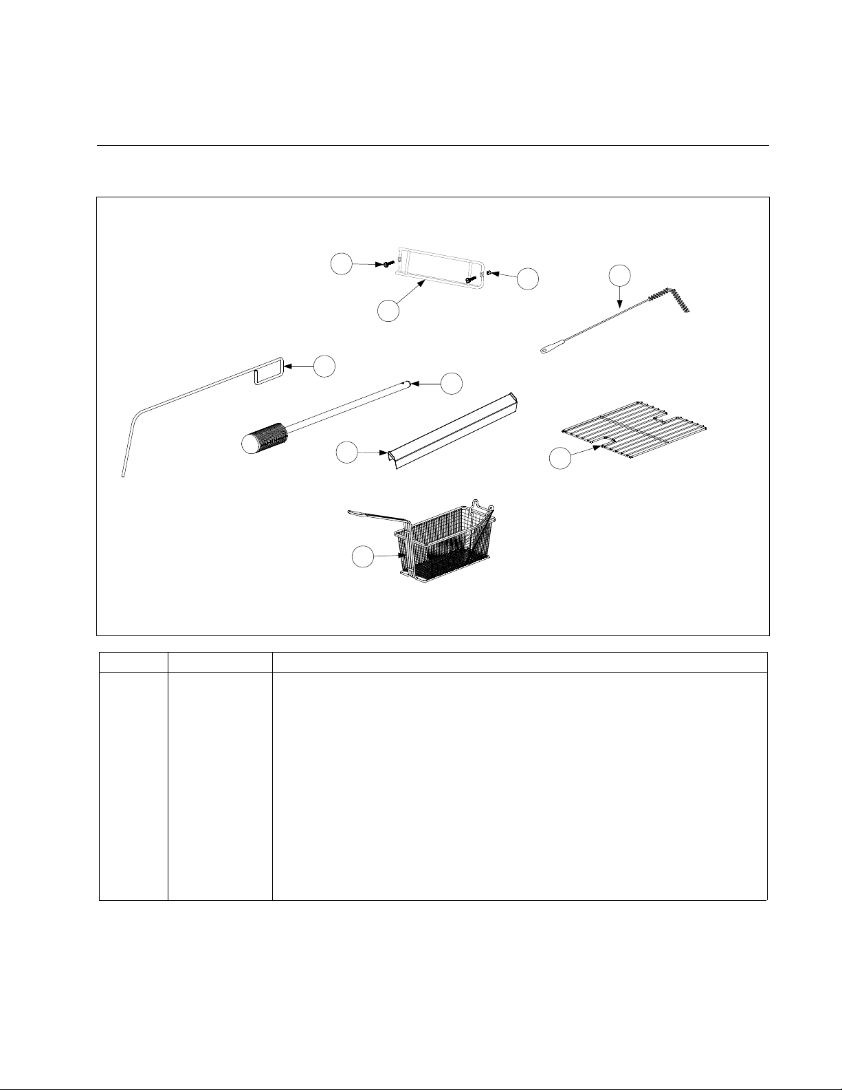
8.1 Accessories
CHAPTER 8: PARTS LIST
1
3
2
5
6
7
9
8
ITEM PART # COMPONENT
1 809-0989 Thumbscrew, ¼ -20 X 1-inch
2 810-2793 Hanger, Wireform Basket
3 809-0921 Spacer, Basket Hanger
4 803-0278 L-Shaped Brush
5 803-0197 Cleanout Rod, 27-inch
6 803-0209 Brush, Frypot
7 210-9083 Connecting Strip, Frypot
8 803-0132 Rack, Full-Vat Basket Support
9 803-0271 Basket, Twin
* 803-0352 5/16” Nut Driver
* 803-0002 Powder, Filter (80 1-Cup Applications)
* 803-0170 Paper, Filter (100-Sheet Pack)
* Not illustrated.
4
PDF compression, OCR, web optimization using a watermarked evaluation copy of CVISION PDFCompressor
8-1
Page 2
8.2 Cabinetry
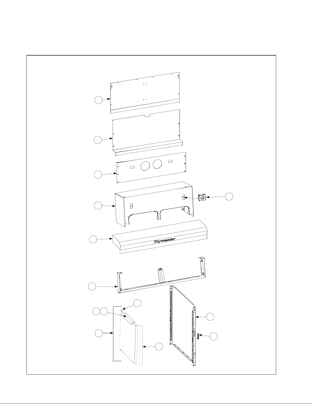
8.2.1 FPPH217 Backs, Panels, Doors, Handles, Sides, Tilt Housings & Top Caps
1
2
3
5
4
6
7
11
109
12
8
13
14
PDF compression, OCR, web optimization using a watermarked evaluation copy of CVISION PDFCompressor
8-2
Page 3

8.2.1 FPPH217 Backs, Panels, Doors, Handles, Sides, Tilt Housings & Top Caps
ITEM PART # COMPONENT
1 210-9157 Back Panel, Upper Single FPH117
210-9032 Back Panel, Upper 2-Station FPPH217
2 210-9158 Back Panel, Center Single FPH117
210-9028 Back Panel, Center 2-Station FPPH217
3 210-9030 Back Panel, Lower 2-Station FPPH217
106-4953 Tilt Housing Assembly, Single FPH117 includes transformer, bracket &
hardware.
4 824-1513 Tilt Housing, Single FPH117
824-1496 Tilt Housing, 2-Station FPPH217
5 826-1351 Nut Retainer, ¼-20 (Pkg. of 10)
6 106-5195 Top Cap, Single FPH117
106-5196 Top Cap, 2-Station FPPH217
* 200-9614 Heat Shield, Single FPH117
* 200-9610 Heat Shield, 2-Station FPPH217
7 106-5016 Frame, Control Panel, Single FPH117
106-5221 Frame, Control Panel, 2-Station FPPH217
8 106-4979 Door Assembly Single FPH117 (includes items below plus 210-9214)
* 824-1516 Door, Universal Single FPH117
* 210-9215 Liner, Door Universal Single FPH117
* 809-0500 Screw, #10 – ½ Hex TR HD SS
* 826-1343 Spring, Door Pin Hinge Single FPH117 and FPPH217 (Pkg. of 10)
106-4769 Door, Left or Right (Left shown – move handle to opposite side for Right)
2-Station FPPH217
9 809-0500 Screw, #10 X ½-inch Hex Head FPPH217
10 210-9214 Handle, Door
11 106-0554 Pin Assembly, Door FPH117, FPPH217
12 211-9130 Side, Cabinet Left, Single FPH117
211-8466 Side, Cabinet Left, 2-Station FPPH217
212-9130 Side, Cabinet Right, Single FPH117
212-8466 Side, Cabinet Right, 2-Station FPPH217
13 810-1105 Magnet, Door
14 210-9086 Door Tab
* 210-9154 Bracket, Transformer, Single FPH117
* 810-0045 Bushing, Transformer Bracket Single FPH117
* 809-0123 Screw, #10 –3/4 Truss Slotted Head
* 826-1376 Nut KEPS 10-32 HX ZP (Pkg. of 10)
* 210-9188 Hinge, Door Single FPH117
* 807-0064 Transformer, 480V/120V 150VA Single FPH117
* Not illustrated.
PDF compression, OCR, web optimization using a watermarked evaluation copy of CVISION PDFCompressor
8-3
Page 4
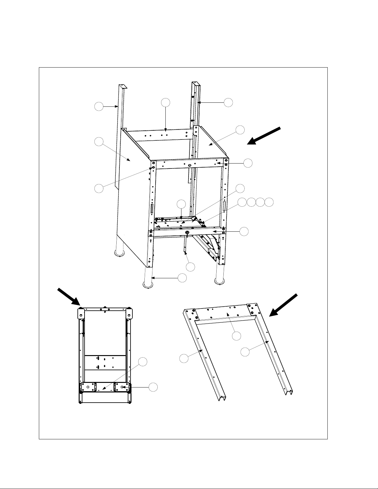
8.2.2 Cabinet Bases, Braces, and Associated Parts
8.2.2.1 FPH117 Single
Rear of
Fryer
16
11
4
3
5
Cabinet
Assembly
17
2
15
7
21
14
9 10 12 13
1
Base
Assembly
18
20
8
6
19
PDF compression, OCR, web optimization using a watermarked evaluation copy of CVISION PDFCompressor
8-4
Page 5

8.2.2.1 FPH117 Single
ITEM PART # COMPONENT
106-4942 Assembly, Cabinet Single FPH 117
1 106-4949 Brace Assembly, Filter Stop
2 210-9141 Rail, Front Top Single
3 210-9140 Brace, Rear Horizontal Single
4 106-4947 Upright, Rear Enclosure Left
5 106-4946 Upright, Rear Enclosure Right
6 106-4950 Leg Pad Assembly
7 106-4951 Filter Rail Assembly
8 106-4952 Base Assembly
9 826-1362 Nut, ¼-20 Hex (Pkg. of 10)
10 809-0191 Washer, ¼ Lock Spring ZP
11 809-0500 Screw, #10 - ½ Hex Head SS
12 809-0417 Nut, Flange ¼ - 20 Serr
13 809-0508 Bolt, 14 – 20 x 1 ¼ AT HX HD SS
14 823-3103 Leg W/A Single FP
15 210-9150 Mount, Motor Single FP
16 211-9130 Cabinet, Side Panel Left
17 212-9130 Cabinet, Side Panel Right
18 210-9148 Channel, Rear Single
19 211-9149 Channel, Side Left
20 212-9149 Channel, Side Right
21 823-5313 Filter Pan Stop
PDF compression, OCR, web optimization using a watermarked evaluation copy of CVISION PDFCompressor
8-5
Page 6
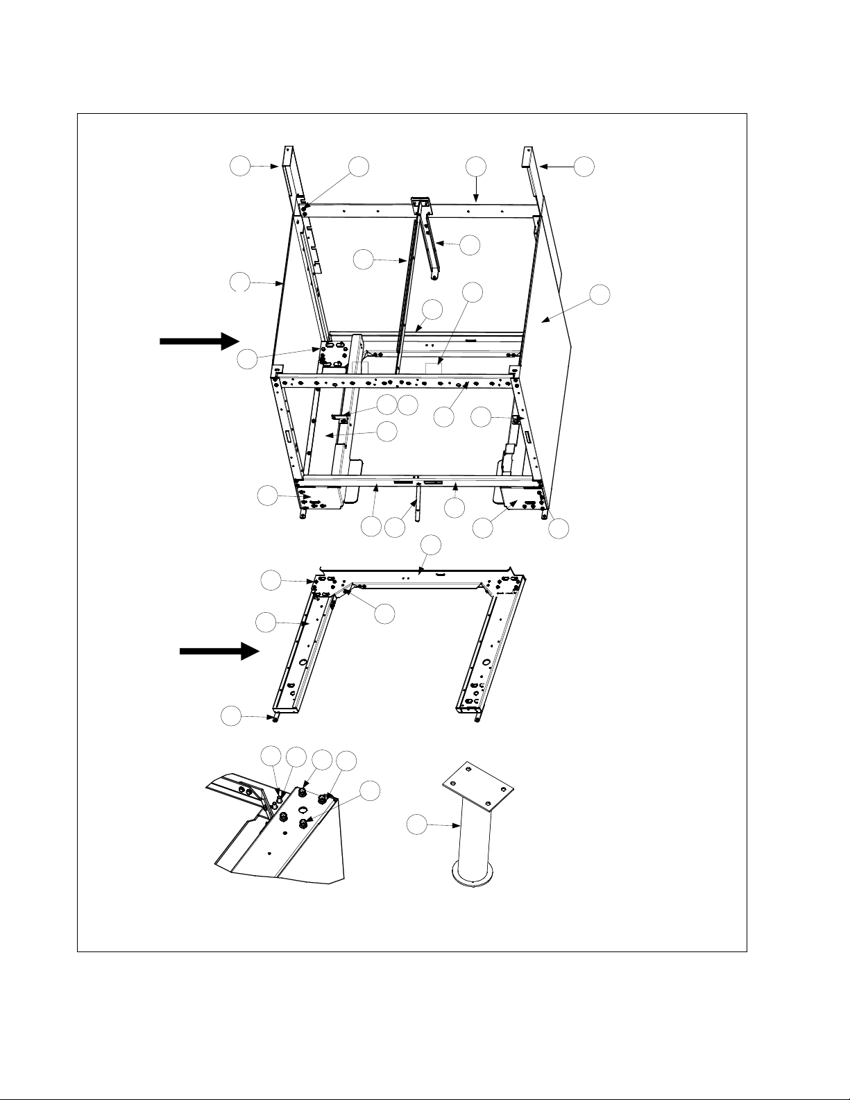
8.2.2.2 FPPH217 Double Station Fryer
Cabinet
Assembly
11
2
22
7
30
3
19
14
33
8 12
10
5
29
31
6
4
27
1918
13
19
Base Assembly
24
28
26
15
20
16
25
17
21
23
PDF compression, OCR, web optimization using a watermarked evaluation copy of CVISION PDFCompressor
8-6
Page 7

8.2.2.2 FPPH217 Double Station Fryer
ITEM PART # COMPONENT
106-4919 Cabinet Assembly, FPP Electric Double S/S
1 106-4766 Upright Assembly, Right
2 106-4765 Upright Assembly, Left
3 106-4767 Base Assembly, FPP DBL Electric
4 210-8978 Support, Right Filter Pan
5 210-8979 Support, Left Filter Pan
6 210-8984 Support, Cross Cabinet
7 210-8986 Divider, Cabinet
8 210-8987 Brace, Front Horizontal Two-Station Fryer
9 210-8989 Brace, Rear Horizontal Two-Station Fryer
10 210-9116 Shield, Channel
11 211-8466 Side, Left Cabinet
12 211-8977 Support, Contactor Box Station 1
13 212-8466 Side, Right Cabinet
14 212-8977 Support, Contactor Box Station 2
15 826-1389 Screw, Hex Head ¼ -20x ¾ (Pkg. of 10)
16 809-0190 Washer, Flat ¼ SS
17 809-0191 Washer, ¼ Lock Spring
18 826-1376 Nut, 10-32 Keps Hex (Pkg. of 10)
19 826-1374 Screw, #10x ½-inch Hex Washer Head (Pkg. of 25)
20 809-0417 Nut, ¼ -20 Hex Flange
21 809-0429 Bolt, ¼-20 x 2-inch Hex Head
22 824-1488 Bracket, Rear Support
23 823-5241 Leg, Marine Shipboard (Mounts with Items 20 and 21)
24 210-6862 Hinge, Door
25 210-8993 Brace, Rear Channel Corner
26 826-1374 Screw, #10 X ½-inch Hex Washer Head (Pkg. of 25)
27 823-5105 Channel, Base Rear FPP Two-Station Fryer
28 823-5106 Channel, Base Side
29 810-2346 Magnet, Door
30 210-9023 Bracket, Frypot
31 823-5313 Filter Pan Stop
PDF compression, OCR, web optimization using a watermarked evaluation copy of CVISION PDFCompressor
8-7
Page 8
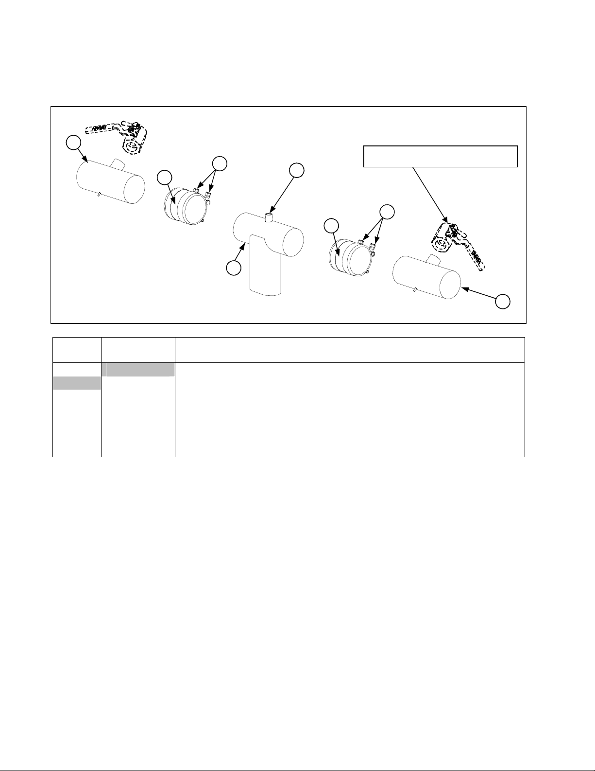
8.3 Drain System Components
8.3.1 FPPH217 Euro-Look Drain Tube Sections and Associated Parts
1
4
3
2
5
3
See Page 8-10 for Drain Valve
4
ITEM
EURO-LOOK
COMPONENT
PART #
1 Drain Tube, Left/Right End Short
823-5048 Full-Vat
2 823-5049 Drain Outlet
3 816-0625 Sleeve
4 809-0969 Clamp
5 810-2492 Fitting, Quick-Connect Straight (receives Teflon vent tube)
* 811-1071 Tube, Teflon Vent
Not illustrated.
1
PDF compression, OCR, web optimization using a watermarked evaluation copy of CVISION PDFCompressor
8-8
Page 9
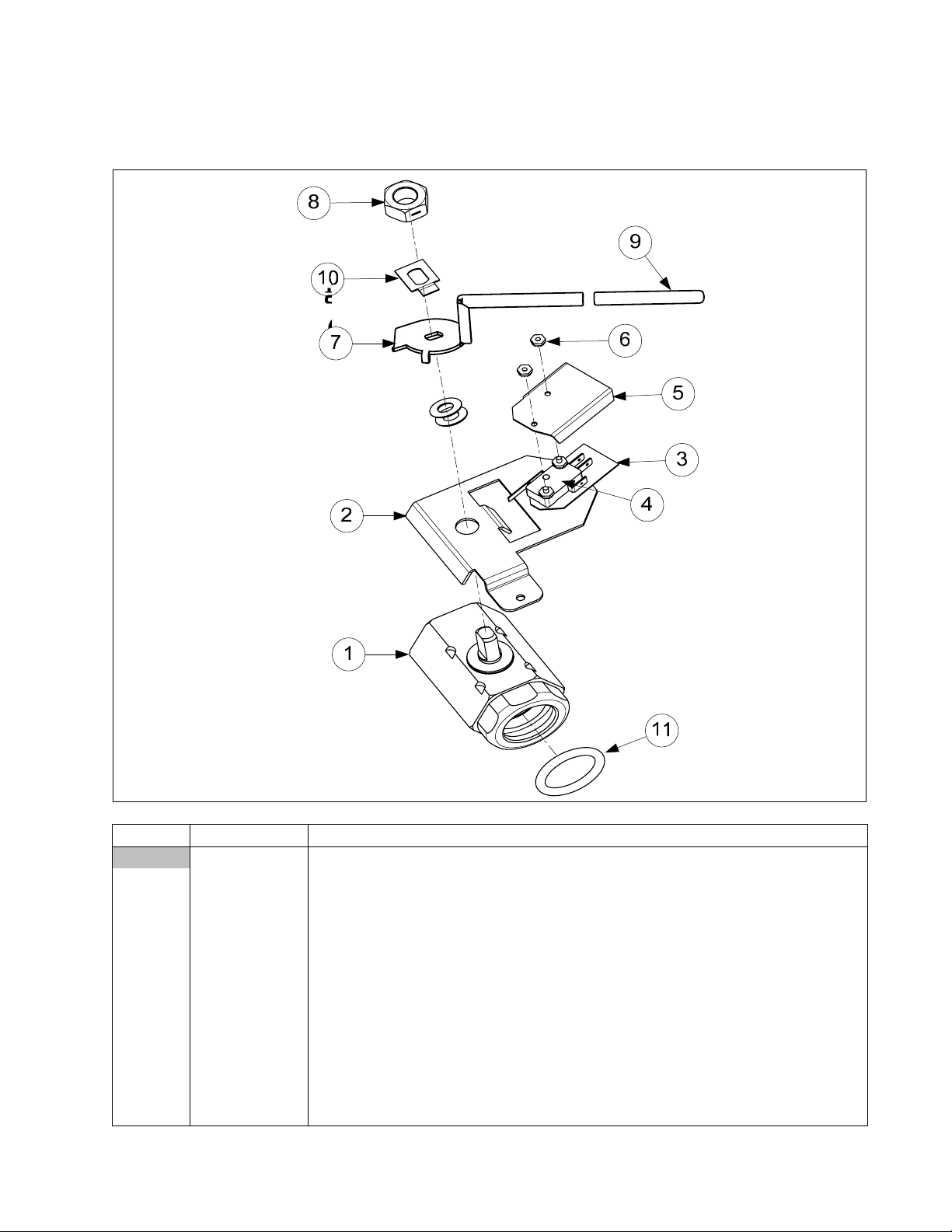
8.3.2 Drain Valve Assembly and Component Parts
8.3.2.1 FPH117 Single Drain Valve Assembly
ITEM PART # COMPONENT
106-4962 Valve Assembly, Full Vat Drain
1 810-2946 Valve, 1¼-inch Full-Vat Drain Single SS
2 106-5391 Bracket Assembly, Full-Vat Drain Safety Switch
3 816-0220 Insulation, Drain Safety Switch
4 807-2103 Microswitch, CE Straight Lever
5 210-9178 Cover, Dual Vat Drain Safety Switch
6 826-1366 Nut, 4-40 Keps Hex (Pkg. of 25)
7 824-1602 Handle, Full-Vat Drain Valve
8 210-9203 Nut, ½-13 2-Way Hex Lock SS
9 816-0639 Cap, Red Handle
10 210-9177 Retainer, Nut Drain Valve FV
11 816-0135 O-ring, Round Drain
* 813-0605 1 ½” Drain Valve Extension Down Spout
PDF compression, OCR, web optimization using a watermarked evaluation copy of CVISION PDFCompressor
8-9
Page 10

8.3.2.2 FPPH 217 Euro-Look Drain Valve Assembly and Component Parts
ITEM Euro-Look
PART #
106-4920 Valve Assembly, Full Vat Drain
1 816-0639 Cap, Red Handle
2 816-0220 Insulation, Drain Safety Switch
3 806-8137 Bracket Assembly, Full-Vat Drain Safety Switch
4 810-2946 Valve, 1.25-inch Full-Vat Drain
5 809-0540 Nut, ½-13 2-Way Hex Lock
6 210-9025 Retainer, Full-Vat Drain Valve Nut
7 824-1602 Handle, Full-Vat Drain Valve
8 210-9178 Cover, Dual Vat Drain Safety Switch
9 826-1366 Nut, 4-40 Keps Hex (Pkg. of 25)
10 807-2103 Microswitch, CE Straight Lever
11 810-1165 Washer, Teflon Drain Valve
12 210-8966 Support, 3” Drain
13 816-0135 Round Drain O-Ring
* WIR0572 Wire Bundle, Drain Safety Switch
* Not illustrated.
COMPONENT
PDF compression, OCR, web optimization using a watermarked evaluation copy of CVISION PDFCompressor
8-10
Page 11

8.4 Electronics and Wiring Components
8.4.1 Component Boxes
8.4.1.1 FPH117 Single Component Box
15
4
16
9
1711
23
12 14
5
18
1
13
6
19
8 20 22
10 7
ITEM PART # COMPONENT
106-4973 Component Box Assembly
1 106-0313 Wire Assembly, Component SFP120
2 806-7179SP Sound Device
3 806-7935 PCP Assembly, Interface
4 106-4974 Component Box W/ Studs
5 807-0012 Relay, 18AMP 1/3 HP 24V Coil
6 807-0065 Block, Terminal
7 807-0069 Circuit Breaker, 10A
8 807-0070 Terminal, Ground Lug
9 807-0855 Transformer, 120V 50/60 – 12V 20A
10 807-1612 Clamp, 3/8 Connector Type (Thin Screw)
Continued on the following page
PDF compression, OCR, web optimization using a watermarked evaluation copy of CVISION PDFCompressor
8-11
Page 12

8.4.1.1 FPH117 Single Component Box cont.
ITEM PART# COMPONENT
11 807-2181 Transformer, Power 100-120V/24V 62VA
12 809-0102 Screw, 8 – 32 x 3/8 TR SL HD ZP
13 809-0104 Screw, 8 – 32 x ½ TR SL HD ZP
14 809-0247 Nut, 8 – 32 Hex KEPS ZP
15 809-0250 Nut, 6 – 32 Hex KEPS ZP
16 809-0349 Spacer, 4mm x 6mm Aluminum
17 809-0360 Screw, 8 x 3/8 Type 8 Hex Washer SL HD ZP
18 826-1374 Screw, #10 – ½ Hex Head (Pkg. of 25)
19 810-0045 Bushing, .875 Dia Hole 11/16
20 810-1164 Block, 1 Plg Screwless Terminal
21 812-0368 Conduit, Flex 3/8”
22 816-0217 Paper, Insulating Terminal Block CE
23 WIR-0428 Wire Assembly, Navy SFP Component
24 WIR-0581 Wire Assembly, Transformer 440V
PDF compression, OCR, web optimization using a watermarked evaluation copy of CVISION PDFCompressor
8-12
Page 13

8.4.1.2 FPPH 217 Component Boxes
4 12 159 11 16165
Left Component Box
Complete Assy.
106-4911
24
2526
19163
23
22
10 16
11 16
7
162
6
17
14
13
18
98
1
NOTE 1: The trans form er on t he lef t s ide of the c om ponent
box (Item 11) and the relay (Item 5) is present only in the left
component box.
NOTE 2: See Page 8-22 f or Componen t Box 15-Pi n W iring
Harnesses.
Right Component Box
Complete Assy.
106-4912
19163
23
162
98
ITEM PART # COMPONENT
1 106-4757 Box Assembly, Component
2 210-9002 Bracket, Component Box Strain Relief
3 210-9003 Bracket, Circuit Breaker
4 806-9495SP Terminal Block and Wire Assembly
5 807-0012 Relay, 18 Amp ⅓ HP 24V Coil
6 826-1337 Terminal, ¼-inch Push-on (Pkg. of 5)
7 807-0121 Bushing, Heyco Plastic AB-625-500
8 807-1321 Holder, AGC Panel-Mount ¼-inch Fuse
9 807-1597 Fuse, 3 Amp Slow-Blow
10 807-0855 Transformer, 100-120V/24V 20VA
11 807-2181 Transformer, 100-120V/12V 60VA
12 826-1366 Nut, 4-40 Keps Hex (Pkg. of 25)
13 809-0250 Nut, 6-32 Keps Hex
14 809-0349 Spacer, 4mm X 6mm Aluminum
15 826-1359 Screw, 4-40 X ¾-inch Slotted Round Head (Pkg. of 25)
16 809-0359 Screw, #8 X ¼-inch Hex Washer Head
17 806-7935 Interface Board
807-3932 Relay, 12VDC SPDT 12 Amp
18 106-5120 Handle Assembly, rear flush FV
19 807-0069 Circuit Breaker, 10 Amp
20 210-9118 Guard, Finger
21 810-2445 Plug, Button
4 12 15
10 16
11 16
7
6
17
14
13
18
1
21
20
16
PDF compression, OCR, web optimization using a watermarked evaluation copy of CVISION PDFCompressor
8-13
Page 14

8.4.1.2 FPPH 217 Component Boxes cont.
ITEM PART# COMPONENT
22 210-8995 Brace, Component Box
23 807-1083 Bushing, Heyco
24 807-3868 Strain Relief
25 809-0581 Nut, ½ NPT Locking
26 809-0582 Washer ½ NPT Locking
PDF compression, OCR, web optimization using a watermarked evaluation copy of CVISION PDFCompressor
8-14
Page 15

8.4.2 Contactor Boxes
8.4.2.1 FPH117 Single Contactor Box
15
13
11
16
9
1
3 2
10
6
4
14
5
8
18
7
12
17
ITEM PART # COMPONENT
106-4978 Contactor Box Assembly
1 106-5131 Wire Assembly, CI Single FP
2 106-5132 Wire Assembly, HV DV LT Contactor Single
3 106-5133 Wire Assembly, HV DV RT Contactor Single
4 210-9440 Cover, Contactor Box Single FP
5 210-9751 Box, Contactor Single FP
6 807-0012 Relay, Tilt 18 AMP 1/3 HP 24V Coil
7 807-0878 Block, Terminal 3 Lug 12 P
8 807-1338 Fitting, Plastic ¾ Dia Conduit
9 807-1683 Relay, Power 12 VDC
10 807-2284 Contactor, 50 AMP Mech 24V Coil
11 807-2434 Relay, Shunt 24V Coil 18AMP
12 809-0096 Screw, 6 – 32 x 5/8 Bindings SL HD ZP
13 809-0102 Screw, 8 – 32 x 3/8 TR HD ZP
14 809-0250 Nut, 6 – 32 KEPS HX ZP
15 809-0266 Screw, 10- ½ Phil TR HD ZP
PDF compression, OCR, web optimization using a watermarked evaluation copy of CVISION PDFCompressor
8-15
Page 16

8.4.2.1 FPH117 Single Contactor Box cont.
ITEM PART# COMPONENT
16 809-0360 Screw, 8 x 3/8 HX Washer SL HD ZP
17 809-0500 Screw, 410 SS #10x1/2 Hex Washer HD Type B Point
18 812-0917 Conduit, ¾ x 12 LG Flexible
* WIR0427 Wire Assembly, Navy Single FP
* WIR0650 Wire Assembly, Contactor Single FP
* Not Illustrated
PDF compression, OCR, web optimization using a watermarked evaluation copy of CVISION PDFCompressor
8-16
Page 17

8.4.2.2 FPPH217 Contactor Box
Left Complete
Assy. 106-4924
11
16
17
Right Complete Assy.
106-4923
8
9
11
14
5
12
1
3
15
24
10
6
13
7
NOTE 1: Left and right contactor box assemblies are mirror images of one another. With the
exception of the box itself, all components of a left-hand assembly, including the lid, are the same as
those in the corresponding right-hand assembly and vice versa.
NOTE 2: See Page 8-21 for Contactor Box Wiring Assembly
ITEM PART # COMPONENT
1 826-1374 Screw, #10 x ½ Hex Head (Pkg. of 25)
2 106-5149 Wire Harness, Contactor Box Right Element FPP
3 106-5150 Wire Harness, Contactor Box Left Element FPP
4 106-5152 Wire Harness, Contactor Box CI FV FPP
5 210-9677 Door, Contactor Box w/o Hinge
6 807-0012 Relay, Tilt 18 Amp ⅓ HP 24V Coil
7 807-0064 Transformer, 480V/120V 150VA
8 807-0070 Terminal, Ground Lug
9 826-1339 Bushing, .375 Split (Pkg. of 10)
10 807-1683 Relay, Power 12 VDC
11 807-2284 Contactor, 50 Amp MECH 24V Coil
12 807-2434 Relay, Shunt 24V Coil 18 Amp
13 826-1358 Nut, 6-32 Keps Hex (Pkg. of 25)
14 826-1376 Nut, 10-32 Keps Hex (Pkg. of 10)
Note: On single units,
the transformer is
located in the tilt
housing area. On
double units, the
transformer is located
inside the contactor
box.
15 809-0448 Clip, Tinnerman C1350-10A
16 106-5117 Box Assembly, FPP Right Contactor
17 106-5118 Box Assembly, FPP Left Contactor
* 809-0360 Screw, #8 X ⅜-inch Hex Washer Slot Head
* 809-0123 Screw, #10 X ¾-inch Slot Head
* 826-1365 Screw, 6-32 X ⅜-inch Slot Head (Pkg. of 25)
* 210-9634 Lid, Left or Right Contactor Box
** Not illustrated.
PDF compression, OCR, web optimization using a watermarked evaluation copy of CVISION PDFCompressor
8-17
Page 18

8.4.3 Heating Element Assembly and Associated Parts
3
4
9
7
6
8
10
20
5
11
1
1
2
1312
15
1413
16
17
18
19
22
NOTES:
The only difference between element assemblies for different voltage and kW ratings is the element itself (Item 1)
Items 21 and 22 are shown as associated parts. They are not part of the element assembly.
21
PDF compression, OCR, web optimization using a watermarked evaluation copy of CVISION PDFCompressor
8-18
Page 19

8.4.3 Heating Element Assembly and Associated Parts cont.
ITEM PART # COMPONENT
106-4964 Element Assembly FV 440V 17kW w/ Lift Handle Single FPH117
106-4922 Element Assembly FV 480V 17kW w/ Lift Handle FPPH217
1 807-2650 Element, 440V 8.5kW
807-2652 Element, 480V 8.5 kW
2 826-1526 Probe, Temperature Kit (incl. Probe and Tie Wrap)
3 106-4965 Tilt Plate Assembly Single FPH117
106-4921 Tilt Plate Assembly FPPH217
4 106-4966 Bracket, Left Spring Slot Single FPH117
106-4759 Bracket, Left Spring Slot FPPH217
5 106-4967 Bracket, Right Spring Slot Single FPH117
106-4760 Bracket, Right Spring Slot FPPH217
6 210-9183 Tilt Plate, Single FPH117
210-9108 Tilt Plate, FPPH217
7 810-0035 Hinge
8 826-1330 Screw, 10-32 X ⅜-inch Slotted Truss Head (Pkg. of 25)
9 826-1376 Nut, 10-32 Keps Hex (Pkg. of 10)
10 807-1025 Bushing, .375-inch Split (Pkg. of 10)
11 816-0480 Plug, .375-inch Dome
12 910-5022 Bracket, Temperature Probe
13 809-0503 Screw, 8-32 X ⅜-inch Slotted Hex Head
14 210-9180 Clamp, Element (Short) Single FPH117
210-9109 Clamp, Element (Short) FPPH217
15 210-9181 Clamp, Element (Long) Single FPH117
210-9110 Clamp, Element (Long) FPPH217
16 910-3681 Support, Full-Vat Element Rear
17 823-2377 Support, Full-Vat Element Front
18 810-2971 Handle, Element Lift SS
19 826-1364 Pin, .125 X .5-inch Split (Pkg. of 25)
20 809-0567 Tie-Wrap, Metal
21 210-9192 Bracket, Lower Spring Slot Single FPH117
210-9001 Bracket, Lower Spring Slot (Stainless) FPPH217
22 810-2945 Spring, Element FPH117, FPPH217
PDF compression, OCR, web optimization using a watermarked evaluation copy of CVISION PDFCompressor
8-19
Page 20

8.4.4 Remote Digital Controller
Remote Digital Controller P/N 106-4931
(not shown Remote Controller Cable P/N 106-5142)
8.4.5 Wiring Assemblies and Harnesses
8.4.5.1 FPPH217 Contactor Box Wiring Assembly – 12-Pin Full-Vat C-1
1
2
3
4
5
6
7
8
9
10
11
12
BLACK
GREEN/YELLOW
WHITE
BROWN
WHITE
BLACK
RED
ORANGE
BLACK
YELLOW
P/N 106-2522
8.4.5.2 FPPH217 Contactor Box Wiring Assemblies – 6-Pin (Left Element)
1
2
3
4
5
6
BLUE
BLUE
BLUE
BLACK
BLACK
BLACK
P/N 106-3465 17kW
PDF compression, OCR, web optimization using a watermarked evaluation copy of CVISION PDFCompressor
8-20
Page 21

8.4.5.3 FPPH217 Contactor Box Wiring Assemblies – 9-Pin (Right Element)
1
2
3
4
5
6
7
8
9
BLUE
BLUE
BLUE
BLACK
BLACK
BLACK
P/N 106-3466 17kW
8.4.5.4 FPH117 Single Contactor Box Wiring Assemblies
1
2
3
4
5
6
7
8
9
GREEN
RED
ORANGE
ORANGE
RED
P/N 106-0313SP 17kW
8.4.5.5 FPPH217 Main Wiring Harness
15-Pin Male Connector
807-0804 (Rear of Fryer)
C6
1
12-Pin Male Connector
807-0160 (Contactor Box)
C1
J6
P/N 807-4033
12-Pin Male Connector
807-0160 (Interface Board)
J1
J4
J5
J2
4-Pin Female Connector
807-3232 (Drain Safety Switches)
15-Pin Male Connector
807-0804 (Component Box)
6-Pin Male Connector
807-0157 (Used for optional
Basket Lift)
12-Pin Male Connector
807-0160 (Interface Board)
PDF compression, OCR, web optimization using a watermarked evaluation copy of CVISION PDFCompressor
8-21
Page 22

8.4.5.6 FPH117 Single Main Wiring Harness
15-Pin Male Connector
807-0804 (Rear of Fryer)
9-Pin Male Connector
807-0155 (Component Box)
12-Pin Male Connector
807-0160 (Interface Board)
6-Pin Female Connector
807-0158 (Drain Safety Switches)
12-Pin Male Connector
807-0160 (Interface Board)
12-Pin Male Connector
807-0160 (Contactor Box)
P/N 807-4077
8.4.5.7 FPPH217 Component Box Wiring Harness – 15-Pin
P/N 106-2506
8.4.5.8 FPH117 Single Component Box Wiring Harness – 15-Pin
P/N 106-0595
PDF compression, OCR, web optimization using a watermarked evaluation copy of CVISION PDFCompressor
8-22
Page 23

8.5 Filtration System Components
8.5.1 FPH117 Single Filtration Components
1
2
25
24
13
3
30
4
31
34
16
15
23
21
26
27
20
38
14
18
19
22
17
36
37
11
12
6
5
8
10
7
9
28
29
35
33
32
PDF compression, OCR, web optimization using a watermarked evaluation copy of CVISION PDFCompressor
8-23
Page 24

8.5.1 FPH117 Single Filtration Components cont.
ITEM PART # COMPONENT
106-4945 Assembly, Filter Pan Single FPH117
1 806-9547 Lid, Single FPH117
2 810-2743 Crumb Tray
3 823-2899 Hold Down Ring
4 900-8933 SanaGrid Filter Screen
5 823-5141 Pan, Filter
6 826-1360 Screw, 10-24 x 5/16 RD SL HD ZP (Pkg. of 25)
7 826-1376 Nut, KEPS, 10 – 32 HX ZP (Pkg. of 10)
8 810-0180 Handle, Door
9 810-2805 Caster, 2” Filter Pan
10 810-2807 Caster, 2” Rigid
11 813-0568 Pipe Plug 1/8 NPT Socket Head
12 823-5142 Tube, Pan Suction Single FP
106-4976 Plumbing Assembly, 120V FV Single FP
13 806-6034 Pump & Motor Assembly, 115V 60 HZ
14 810-2944 Gemini Valve w/out Handle
15 810-1057 Flex Line 5/8” O.D. x 13” Long
16 810-1067 Flex Line 5/8” O.D. x 8.5” Long
17 810-1668 Adapter, Male 7/8” O.D. x ½”
18 813-0022 Nipple, ½” x Close N.P.T. B.M.
19 813-0098 Nipple, ½” x 6.50” N.P.T. B.M. Pipe
20 813-0616
21 813-0331 Elbow, W/Side Outlet – ½” NPT
22 813-0469 Cap, Pipe ½” BM
23 210-9197 Handle, Right RF Valve
24 826-1264 Pump and Gasket Kit, Pump, Viking 4 GPM 2-piece
25 816-0093 Gasket, Pump / Motor
26 809-0514 Cap Screw, 5/16” – 18 NC SAE Grade 5, HX HD
27 809-0194 Washer, Flat 5/16” SAE ZP
106-4951 Rail Assembly, Filter Pan Single FPH117
28 809-0500 Screw, 10 – ½” HX HD SS
29 210-9145 Angle, Joining, Pan Rails Filter Magic
30 211-9147 Leg, Pan Rail FM Left
31 211-9146 Bracket, Attaching Filter Pan Left
32 212-9147 Leg, Pan Rail FM Right
33 212-9146 Bracket, Attaching Filter Pan Right
34 211-9455 Rail, Filter Pan Left
35 212-9455 Rail, Filter Pan Right
36 823-5151 Mount W/A, Male Connector
37 810-0697 Disconnect, Filter Pan Connection (Male)
38 826-1392 O-Ring, Filter Pan Connection (Pkg. of 5)
Elbow, ST ½” x ½” NPT 90° BM
PDF compression, OCR, web optimization using a watermarked evaluation copy of CVISION PDFCompressor
8-24
Page 25

8.5.2 FPPH217 Filtration Components
1
19
18
24
29
2
17
25
16
30
3
4
14
28
12119
8
31
7
6
20
121110
36
35
34
25
18
22
24
23
21
8
27
26
32
33
15
5
13
PDF compression, OCR, web optimization using a watermarked evaluation copy of CVISION PDFCompressor
8-25
Page 26

8.5.2 FPPH217 Filtration Components cont.
(
)
(
)
(
)
(Pkg
)
(
)
(
)
)
g
(
(
)
(Pkg
)
(f
)
d
d
r
r
d
g
r
(Pkg
)
r
ITEM PART # COMPONENT
* 826-1979 Filter Pan Roller Kit
* 826-1980 Service Filter Pan
* 826-1981 Service Filter Pan Assembly
* 826-1392 O-Ring
. of 5; used with Item 5
* 813-0568 Plug, ⅛-inch Socket Head Pipe
* 811-1071 Tubing, ¼-inch OD Teflon Vent
four each of Items 7 and 8
Item 5 minus Item 2
Service Filter Pan above plus Items 3 and 4
component of Item 5; two required
sold by the foot
* 106-2851 Heater Strip Assembly, 208-250V
1 823-5130 Lid
2 810-2743 Crumb Tray (component of Item 5
3 810-2091 Hold Down Rin
4 200-2124 SanaGrid Filter Screen
5 106-4925 Pan, One-Piece Filter
6 810-2012 Rail Set, Filter Pan Roller
includes Item 2,)
includes one left and one right
7 810-2198 Roller, Filter Pan and Rail
8 826-1372 Nut, ¼-20 Hex
9 823-4675 Bracket, Lid Support
. of 10
or units built before Feb 04, use 823-3875
10 210-9000 Guide, Filter Pan Li
11 809-0503 Screw, 8-32 X ½-inch Slotted Truss Hea
12 809-0247 Nut, 8-32 Hex Keps
13 823-5133 Suction Tube
14 210-8979 Rail, Left Filte
15 210-8978 Rail, Right Filte
16 807-3859 Kit, Motor and Gasket 220-240V
17 826-1264 Pump and Gasket Kit
18 807-2484 Valve, ¼-inch Solenoi
19 810-2493 Fitting, ¼ -inch x 90° Quick Connect
20 813-0342 Elbow, ½-inch 45° Street
21 813-0530 Tee, ½-inch X ¼-inch X ½-inch Reducin
22 813-0087 Nipple, ½-inch Close
23 813-0838 Nipple, ¼-inch Close
24 813-0304 Bushing, ½-inch to ¼-inch Flush
25 810-1668 Adapter, ⅝-inch to ½-inch NPT Male
26 810-1669 Adapter, ⅝-inch to ½-inch NPT Female
27 810-1680 Flexline, 5.0-inch Oil Return
28 810-1057 Flexline, 17.5-inch Oil Return
29 810-1043 Flexline, 11.5-inch Oil Return
30 807-3828 Cable, FootPrint Pro Pump Moto
31 826-1375 Screw, 10-32 X ¾-inch Hex Trim Head
32 210-9016 Bridge, Filter Moto
33 210-9029 Support, Contactor Box
34 813-0003 Tee, ½-Inch
35 813-0298 Nipple, ½-inch 2.0-inch
36 813-0537 Nipple, ¼-inch 2.0-inch
* 810-1043 Flexline, 9.5-inch Oil Return
* 810-1057 Flexline, 13.0-inch Oil Return
* Not illustrated
. of 5
PDF compression, OCR, web optimization using a watermarked evaluation copy of CVISION PDFCompressor
8-26
Page 27

8.6 Frypot Assembly and Thermostat
Frypot P/N 823-5312
8.7 FPPH217 Oil Return System Components
Thermostat Assy.
P/N 806-7543
PDF compression, OCR, web optimization using a watermarked evaluation copy of CVISION PDFCompressor
8-27
Page 28

8.7 FPPH217 Oil Return System Components cont.
ITEM PART # COMPONENT
1 106-5120 Handle Assembly, Full-Vat t R ear F lush C o mple t e
2 813-0469 Cap, ½-inch NPT Pipe
3 807-2103 Microswitch, Straight Lever
4 106-4749 Bracket Assembly
5 210-8998 Bracket, Handle Retainer
6 816-0220 Insulation, Oil Return Microswitch
7 826-1366 Nut, 4-40 Keps Hex (Pkg. of 25)
8 810-2972 Rod, Handle Full-Vat
9 816-0643 Grip, Oil Return Valve Handle
10 809-0601 Clip, Clevis
11 810-2532 Flexline, 7.0-inch
12 810-1067 Flexline, 8.5-inch
13 810-2944 Valve, ½-inch Ball
14 200-5438 Handle, Rear Flush Valve
15 900-2935 Retainer, Oil Return Valve Nut
16 810-1668 Adapter, ⅝-inch to ½-inch NPT Male
17 810-1669 Adapter, ⅝-inch to ½-inch NPT Female
18 813-0165 Elbow, ½-inch X 90° Street
19 813-0570 Elbow, 180° ½-inch NPT
20 813-0022 Nipple, ½-inch X Close NPT
21 813-0298 Nipple, ½-inch X 2.0-inch NPT
22 810-2255 Manifold, Rear Oil Return Two-Station Fryer
PDF compression, OCR, web optimization using a watermarked evaluation copy of CVISION PDFCompressor
8-28
Page 29

8.8 Wiring Connectors, Pin Terminals, Seals, and Power Cords
1
7
13 14 15
2
8
3
9
4
10
16
5
11
17
6
12
18
19
23
20
24
21 22
25
PDF compression, OCR, web optimization using a watermarked evaluation copy of CVISION PDFCompressor
8-29
Page 30

8.8 Wiring Connectors, Pin Terminals, Seals, and Power Cords cont.
ITEM PART # COMPONENT
* 807-3834 Cable, 3-Phase 4-Wire (Fryer Power Cable)
* 807-4142 Cord, Filter System Power 220V 15A
Connectors
1 807-1068 2-Pin Female
2 807-3232 4-Pin Female
3 807-0158 6-Pin Female
4 807-0156 9-Pin Female
5 807-0159 12-Pin Female
6 807-0875 15-Pin Female
7 807-1067 2-Pin Male
8 807-2078 4-Pin Male
9 807-0157 6-Pin Male
10 807-0155 9-Pin Male
11 807-0160 12-Pin Male
12 807-0804 15-Pin Male
13 816-0675 4-Pin Wire Seal
14 816-0676 4-Pin Interface Connector Seal
15 816-0667 6-Pine Wire Seal
16 816-0668 6-Pin Interface Connector Seal
17 816-0669 9-Pin Wire Seal
18 816-0670 9-Pin Interface Connector Seal
19 816-0671 12-Pin Wire Seal
20 816-0672 12-Pin Interface Connector Seal
21 816-0673 15-Pin Wire Seal
22 816-0674 15-Pin Wire Seal
23 826-1341 Terminal, Female Split Pin (Pkg of 25)
24 826-1342 Terminal, Male Split Pin (Pkg of 25)
25 807-2518 Plug, Mate-N-Lock (Dummy Pin)
* Not illustrated.
Power Cords
Universal Mate-N-Lok Seals
PDF compression, OCR, web optimization using a watermarked evaluation copy of CVISION PDFCompressor
8-30
 Loading...