

Page 1
INSTALLATION, OPERATION,
Return to Cover
SERVICE, AND PARTS MANUAL
47 SERIES GAS FRYERS
Frymaster, L.L.C., 8700 Line Avenue, PO Box 51000, Shreveport, Louisiana 71135-1000
TEL: 1-318-865-1711 FAX: (Parts) 1-318-219-7140 (Tech Support) 1-318-719-7135
PRINTED IN THE UNITED STATES
SERVICE HOTLINE
1-800-551-8633
819-5384 02/01
U.S. $16.00
Page 2

47 SERIES GAS FRYERS
TABLE OF CONTENTS
CHAPTER 1: General Information.............................................................................................. 1-1
1.1 Parts Ordering and Service Information............................................................................ 1-1
1.2 Safety Information............................................................................................................. 1-1
1.3 European Community (CE) Specific Information............................................................. 1-2
1.4 Equipment Description...................................................................................................... 1-2
1.5 Installation, Operating, and Service Personnel ................................................................. 1-3
1.6 Definitions......................................................................................................................... 1-3
1.7 Shipping Damage Claim Procedure..................................................................................1-3
CHAPTER 2: Installation Instructions........................................................................................2-1
2.1 General Installation Requirements.................................................................................... 2-1
2.2 Caster/Leg Installation ......................................................................................................2-2
2.3 Pre-Connection Preparations............................................................................................. 2-3
2.4 Connection to Gas Line..................................................................................................... 2-4
2.5 Converting to Another Gas Type ...................................................................................... 2-6
CHAPTER 3: Operating Instructions..........................................................................................3-1
3.1 Start-Up Procedure............................................................................................................ 3-2
3.2 Boiling-Out the Frypot...................................................................................................... 3-3
3.3 Shutting the Fryer Down................................................................................................... 3-4
3.4 Controller Operation and Programming............................................................................ 3-4
Computer Magic III Controller ......................................................................................... 3-5
Thermostat Controller.......................................................................................................3-9
Analog Controller............................................................................................................ 3-10
Digital Controller ............................................................................................................ 3-11
Manual Basket Lift Timer............................................................................................... 3-13
Solid-State Basket Lift Timer ......................................................................................... 3-13
CHAPTER 4: Filtration Instructions ........................................................................................... 4-1
4.1 Draining and Manual Filtering.......................................................................................... 4-1
4.2 FootPrint III Filtration System Operation......................................................................... 4-1
Preparing the Filter Unit for Use....................................................................................... 4-2
Operation of the Filter Unit............................................................................................... 4-3
Changing the Filter Paper.................................................................................................. 4-5
CHAPTER 5: Preventive Maintenance........................................................................................ 5-1
5.1 Fryer Preventive Maintenance Checks and Services ........................................................ 5-1
Daily Checks and Services................................................................................................ 5-1
Weekly Checks and Services ............................................................................................ 5-1
Quarterly Checks and Services.......................................................................................... 5-1
Semi-Annual Checks and Services.................................................................................... 5-4
5.2 FootPrint III Filtration System Preventive Maintenance Checks and Services ................ 5-5
i
Page 3

47 SERIES GAS FRYERS
TABLE OF CONTENTS
CHAPTER 6: Operator Troubleshooting.....................................................................................6-1
6.1 Introduction........................................................................................................................6-1
6.2 Troubleshooting Fryers Equipped with Controllers Other Than CM III...........................6-2
6.3 Troubleshooting Fryers Equipped with Computer Magic III Computers..........................6-9
6.4 Troubleshooting the FootPrint III Filtration System.......................................................6-15
CHAPTER 7: Service Procedures .................................................................................................7-1
7.1 Functional Description.......................................................................................................7-1
Pilot System Configuration................................................................................................7-1
Electronic Ignition Configuration......................................................................................7-1
Control Options .................................................................................................................7-2
Interface Boards.................................................................................................................7-2
Thermostats........................................................................................................................7-7
7.2 Accessing Fryers for Servicing..........................................................................................7-8
7.3 Cleaning the Gas Valve Vent Tube ...................................................................................7-8
7.4 Checking the Burner Manifold Gas Pressure ....................................................................7-8
7.5 Adjusting Burner Ceramic Target Spacing and Alignment...............................................7-8
7.6 Adjusting the Pilot Flame..................................................................................................7-8
7.7 Calibrating the Thermostat Control...................................................................................7-8
7.8 Replacing Fryer Components............................................................................................7-9
7.8.1 Replacing the Controller or Computer ...............................................................7-9
7.8.2 Replacing the Thermostat.................................................................................7-10
7.8.3 Replacing the Temperature Probe ....................................................................7-10
7.8.4 Replacing the High-Limit Thermostat in Fryers with Thermostat Controls ....7-11
7.8.5 Replacing the High-Limit Thermostat in Fryers with Temperature Probes.....7-11
7.8.6 Replacing Control Panel Power Indicator Light in Fryers with Thermostat
Controls.............................................................................................................7-12
7.8.7 Replacing Power or Melt Cycle Switch in Fryers with Thermostat
Controls.............................................................................................................7-12
7.8.8 Replacing Melt Cycle Timer Motor in Fryers with Thermostat Controls........7-12
7.8.9 Replacing Burner Ceramic Targets...................................................................7-13
7.8.10 Replacing the Gas Valve ..................................................................................7-13
7.8.11 Replacing the Pilot Assembly...........................................................................7-14
7.8.12 Replacing Gas Valve High-Limit Thermostat Wire Adapter...........................7-14
7.8.13 Replacing the Frypot.........................................................................................7-14
7.9 Troubleshooting and Problem Isolation...........................................................................7-16
7.9.1 Ignition Failures................................................................................................7-16
7.92 Improper Burner Functioning...........................................................................7-17
7.9.3 Improper Temperature Control.........................................................................7-19
7.9.4 Computer-Related Problems.............................................................................7-19
7.9.5 Filtration Problems ...........................................................................................7-21
ii
Page 4

47 SERIES GAS FRYERS
TABLE OF CONTENTS
7.9.6 Leakage Problems ............................................................................................ 7-22
7.9.7 Modular Basket Lift Malfunctions................................................................... 7-23
7.9.8 Interpretation of Digital Controller Lights....................................................... 7-28
7.10 Troubleshooting Guides.................................................................................................. 7-29
7.10.1 Troubleshooting the 24 VAC Circuit in Units without Interface
Boards............................................................................................................... 7-29
7.10.2 Troubleshooting the 24 VAC Circuit in Units Configured for
Electronic Ignition ............................................................................................ 7-30
7.10.3 Troubleshooting the 24 VAC Circuit in Non-Electronic Ignition
Units................................................................................................................. 7-32
7.10.4 Troubleshooting the Gas Valve on Fryers without Interface Boards............... 7-34
7.10.5 Troubleshooting the Gas Valve on Fryers with Interface Boards.................... 7-35
7.10.6 Troubleshooting the Thermostat ...................................................................... 7-36
7.10.7 Troubleshooting the Temperature Probe.......................................................... 7-37
Probe Resistance Chart..................................................................................... 7-38
7.11 Redesigned FootPrint III Supplemental Information...................................................... 7-40
7.12 Wiring Diagrams.............................................................................................................7-44
CHAPTER 8: Parts List................................................................................................................. 8-1
8.1 Accessories........................................................................................................................ 8-1
8.2 Burner Manifold Assemblies and Component Parts......................................................... 8-2
8.3 Burner Ignition System Components................................................................................ 8-3
8.4 Gas Valve Assemblies and Connection Components ....................................................... 8-4
8.5 Gas Manifold Assemblies ................................................................................................. 8-5
8.6 Cabinet Assemblies and Component Parts........................................................................ 8-6
8.7 Component Box/Shield Component Parts......................................................................... 8-8
8.8 Control Assemblies and Component Parts......................................................................8-10
8.9 Filtration Systems and Component Parts........................................................................ 8-13
8.10 Frypot Assemblies and Component Parts ....................................................................... 8-19
8.11 Modular Basket Lift Component Parts............................................................................ 8-26
8.12 Gas Conversion Kits........................................................................................................ 8-27
iii
Page 5
DANGER
IMPROPER INSTALLATION, ADJUSTMENT, ALTERATION, SERVICE, OR
MAINTENANCE CAN CAUSE PROPERTY DAMAGE, INJURY, OR DEATH. READ THE
INSTALLATION, OPERATING, AND SERVICE INSTRUCTIONS THOROUGHLY
BEFORE INSTALLING OR SERVICING THIS EQUIPMENT.
DANGER
FOR YOUR SAFETY, DO NOT STORE OR USE GASOLINE OR OTHER FLAMMABLE
LIQUIDS OR VAPORS IN THE VICINITY OF THIS OR ANY OTHER APPLIANCE.
DANGER
POST IN A PROMINENT LOCATION THE INSTRUCTIONS TO BE FOLLOWED IN THE
EVENT THE USER SMELLS GAS. THIS INFORMATION SHALL BE OBTAINED BY
CONSULTING THE LOCAL GAS SUPPLIER.
THIS EQUIPMENT IS TO BE INSTALLED IN COMPLIANCE WITH THE BASIC
PLUMBING CODE OF THE BUILDING OFFICIALS AND CODE ADMINISTRATORS
INTERNATIONAL, INC. (BOCA) AND THE FOOD SERVICE SANITATION MANUAL OF
THE FOOD AND DRUG ADMINISTRATION.
COMPUTERS
FCC
This device complies with Part 15 of the FCC rules. Operation is subject to the following two
conditions: 1) This device may not cause harmful interference, and 2) This device must accept any
interference received, including interference that may cause undesired operation. While this device is
a verified Class A device, it has been shown to meet the Class B limits.
CANADA
This digital apparatus does not exceed the Class A or B limits for radio noise emissions as set out by
the ICES-003 standard of the Canadian Department of Communications.
Cet appareil numerique n’emet pas de bruits radioelectriques depassany les limites de classe A et B
prescrites dans la norme NMB-003 edictee par le Ministre des Communcations du Canada.
DANGER
THIS PRODUCT CONTAINS CHEMICALS KNOWN TO THE STATE OF CALIFORNIA
TO CAUSE CANCER AND/OR BIRTH DEFECTS OR OTHER RE PRODUCTIVE HARM.
Operation, installation, and servicing of this product could expose you to airborne
particles of glasswool or ceramic fibers, crystalline silica, and/or carbon monoxide.
Inhalation of airborne particles of glasswool or ceramic fibers is known to the State
of California to cause cancer. Inhalation of carbon monoxide is known to the State
of California to cause birth defects or other reproductive harm.
FRYMASTER FRYERS EQUIPPED WITH LEGS ARE FOR PERMANENT
INSTALLATION. FOR MOVEABLE OR PORTABLE INSTALLATION, FRYMASTER
OPTIONAL EQUIPMENT CASTERS MUST BE USED.
QUESTIONS??? CALL 1-800-551-8633.
Page 6
47 SERIES GAS FRYERS
CHAPTER 1: GENERAL INFORMATION
1.1 Parts Ordering and Service Information
In order to assist you quickly, the Frymaster
Factory Authorized Service Center (FASC) or
Service Department representative requires
certain information about your equipment.
Most of this information is printed on a data
plate affixed to the inside of the fryer door.
Part numbers are found in the Installation, Operation, Service, and Parts Manual.
Parts orders may be placed directly with your
local FASC or distributor. Included with
fryers when shipped from the factory is a list
of Frymaster FASCs. If you do not have
access to this list, contact the Frymaster
Service Department at 1-800-551-8633 or
1-318-865-1711.
When ordering parts, the following information is required:
describe the nature of the problem and have
ready any other information that you think
may be helpful in solving your problem.
RETAIN AND STORE THIS MANUAL IN
A SAFE PLACE FOR FUTURE USE.
1.2 Safety Information
Before attempting to operate your unit, read
the instructions in this manual thoroughly.
Throughout this manual, you will find notations enclosed in double-bordered boxes
similar to the one below.
CAUTION boxes contain information about
actions or conditions that may cause or result
in a malfunction of your system.
CAUTION
Example of a CAUTION box.
Model Number:
Serial Number:
Type of Gas or Voltage:
Item Part Number:
Quantity Needed:
Service information may be obtained by
contacting your local FASC/Distributor.
Service may also be obtained by calling the
Frymaster Service Department at 1-800551-8633 or 1-318-865-1711.
When requesting service, please have the following information ready:
Model Number:
Serial Number:
Type of Gas:
In addition to the model number, serial number, and type of gas, please be prepared to
WARNING boxes contain information about
actions or conditions that may cause or result
in damage to your system, and which may
cause your system to malfunction.
WARNING
Example of a WARNING box.
DANGER boxes contain information about ac-
tions or conditions that may cause or result in
injury to personnel, and which may cause
damage to your system and/or cause your system to malfunction.
DANGER
Hot cooking oil or shortening causes
severe burns. Never attempt to move a
fryer containing hot cooking
oil/shortening or to transfer hot
cooking oil/shortening from one
container to another.
1-1
Page 7
47 SERIES GAS FRYERS
CHAPTER 1: GENERAL INFORMATION
Your fryer is equipped with automatic safety
features:
1. High temperature detection shuts off gas to
the burner assembly should the controlling
thermostat fail.
2. An optional safety switch built into to the
drain valve prevents burner ignition with
the drain valve even partially open.
1.3 European Community (CE)
Specific Information
The European Community (CE) has established certain specific standards regarding
equipment of this type. Whenever a difference exists between CE and non-CE
standards, the information or instructions concerned are identified by means of shadowed
boxes similar to the one below.
III built-in filtration system which prolongs
the useful life of your oil or shortening.
Fryer s eq uip ped wit h Foo tP rin t III bu ilt-in filtration systems are shipped completely
assembled. Fryers without the FootPrint III
require installation of legs or optional casters
at point of use. All fryers are shipped with a
package of standard accessories. Each fryer is
adjusted, tested, and inspected at the factory
before crating for shipment.
Frypots are constructed of welded, heavygauge stainless steel. Heating is supplied by a
burner assembly having multiple gas jets that
are focused on ceramic targets located around
the lower side of the frypot. The burner assembly can be configured for natural gas,
propane, or manufactured gas as required by
the customer. A drain is tapped into the center
of the frypot, with a front-controlled manual
ball valve.
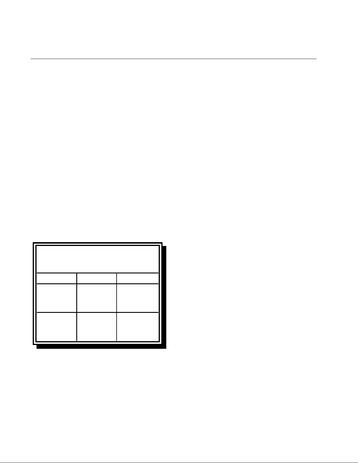
Non-CE Standard
for Incom ing Gas Pressures
Gas Minimum Maxim um
6" W.C.
Natural
LP
1.4 Equipment Description
Fryers in the 47 Series are of an open-pot design with no tubes and have a hand-sized
opening into the deep cold zone, which makes
cleaning the stainless frypot quick and easy.
Units consisting of a battery of two or more
fryers may also be equipped with a FootPrint
1.49 kPa
14.93 mbar
11" W.C.
2.74 kPa
27.37 mbar
14" W.C.
3.48 kPa
34.84 mbar
14" W.C.
3.48 kPa
34.84 mbar
Each fryer is equipped with a thermostat probe
for precise temperature control. The probe is
located on the centerline of the frypot for rapid
response to changes in loads and to provide
the most accurate temperature measurement.
47 Series fryers may be equipped with an optional Melt Cycle feature which pulses the
burner on and off at a controlled rate. The
melt cycle feature is designed to prevent
scorching and uneven heating of the frypot for
customers who use solid shortening.
The controls on your fryer vary depending on
the model and configuration purchased. Control options include one or more thermostat
controls (standard), digital controllers, basket
lift timers, or Computer Magic III compu ters.
Each type is covered in detail in Chapter 3,
Fryer Operating Instructions.
1-2
Page 8

47 SERIES GAS FRYERS
CHAPTER 1: GENERAL INFORMATION
1.5 Installation, Operating, and Service Personnel
Operating information for Frymaster™
equipment has been prepared for use by
qualified and/or authorized personnel only, as
defined in Section 1.6.
All installation and service on Frymaster™ equipment must be performed by qualified, certified, licensed, and/or authorized installation or service personnel, as d efined in Section 1.6.
1.6 Definitions
QUALIFIED AND/OR AUTHORIZED OPERATING
PERSONNEL
Qualified/authorized operating personnel are
those who have carefully read the information
in this manual and have familiarized
themselves with the equipment functions, or
who have had previous experience with the
operation of the equipment covered in this
manual.
been authorized by Frymaster Corporation
to perform service on
Frymaster™ equipment.
All authorized service personnel are required
to be equipped with a complete set of service
and parts manuals, and to stock a minimum
amount of parts for Frymaster™ equipment.
A list of Frymaster Factory Authorized
Service Centers (FASC) was included with the
fryer when shipped from the factory. Failure
to use qualified service personnel will void
the Frymaster Warranty on your equipment.
1.7 Shipping Damage Claim Procedure
Your Frymaster™ equipment was carefully inspected and packed before leaving the factory.
The transportation company assumes full responsibility for safe delivery upon its
acceptance of the equipment for transport.
What to do if your equipment arrives
damaged:
1. File a claim for damages immediately,
regardless of the extent of damages.
QUALIFIED INSTALLATION PERSONNEL
Qualified installation personnel are individuals, or firms, corporations, or companies
which, either in person or through a representative, are engaged in and are responsible for
the installation of gas-fired appliances. Qualified personnel must be experienced in such
work, be familiar with all gas precautions involved, and have complied with all
requirements of applicable national and local
codes.
QUALIFIED SERVICE PERSONNEL
Qualified service personnel are those familiar
with Frymaster™ equipment and who have
2. Inspect for and record all vi sible loss or
damage, and ensure that this information
is noted on the freight bill or express receipt and is signed by the person making
the delivery.
3. Concealed loss or damage that was un-
noticed until the equipment was unpacked
should be recorded and reported to the
freight company or carrier immediately
upon discovery. A concealed damage
claim must be submitted within 15 days of
the date of delivery. Ensure that the shipping container is retained for inspection.
FRYMASTER DOES NOT ASSUME
RESPONSIBILITY FOR DAMAGE OR LOSS
INCURRED IN TRANSIT.
1-3
Page 9

47 SERIES GAS FRYERS
CHAPTER 2: INSTALLATION INSTRUCTIONS
2.1 General Installation Requirements
PROPER INSTALLATION IS ESSENTIAL FOR
EFFICIENT, TROUBLE-FREE OPERATION OF
YOUR FRYER. ANY UNAUTHORIZED ALTERATIONS MADE TO THIS EQUIPMENT WILL
VOID THE FRYMASTER WARRANTY.
Upon arrival, inspect the fryer carefully for
visible or concealed damage. (See Shipping
Damage Claim Procedure in Chapter 1.)
CLEARANCE AND VENTILATION
The fryer(s) must be installed with a 6” (150
mm) clearance at both sides and back when
installed adjacent to combustible construction;
no clearance is required when installed adjacent to noncombustible construction. A
minimum of 24” (600 mm) clearance should
be provided at the front of the fryer.
Adequate distances must be maintained from
the flue outlet of the fryer to the lower edge of
the ventilation filter bank. Filters should be
installed at an angle of 45º. Place a drip tray
beneath the lowest edge of the filter. For U.S.
installation, NFPA standard No. 96 states, “A
minimum distance of 18 in. (450 mm) should
be maintained between the flue outlet and the
lower edge of the grease filter.” Frymaster
recommends that the minimum distance be 24
in. (600 mm) from the flue outlet to the bottom
edge of the filter when the appliance consumes
more than 120,000 BTU per hour.
Information on construction and installation of
ventilating hoods can be found in the NFPA
standard cited above. A copy of the standard
may be obtained from the National Fire Protection Association, Battery March Park,
Quincy, MA 02269.
One of the most important considerations of
efficient fryer operation is ventilation. Make
sure the fryer is installed so that products of
combustion are removed efficiently, and that
the kitchen ventilation system does not produce drafts that interfere with proper burner
operation.
The fryer flue opening must not be placed
close to the intake of the exhaust fan, and the
fryer must never have its flue extended in a
“chimney” fashion. An extended flue will
change the combustion characteristics of the
fryer, causing longer recovery time. It also
frequently causes delayed ignition. To provide the airflow necessary for good combustion and burner operation, the areas surrounding the fryer front, sides, and rear must be kept
clear and unobstructed.
Fryers must be installed in an area with an
adequate air supply and adequate ventilation.
DANGER
Do not attach an apron drainboard to a
single fryer. The fryer may become
unstable, tip over, and cause injury.
The appliance area must be kept free
and clear of combustible material at all
times.
NATIONAL CODE REQUIREMENTS
The type of gas for which the fryer is equipped
is stamped on the data plate attached to the
inside of the fryer door. Connect a fryer
stamped “NAT” only to natural gas, those
stamped “PRO” only to propane gas, and
those stamped “MFG” only to manufactured
gas.
Installation shall be made with a gas connector
that complies with national and local codes,
and, where applicable, CE codes. Quickdisconnect devices, if used, shall likewise
2-1
Page 10
47 SERIES GAS FRYERS
CHAPTER 2: INSTALLATION INSTRUCTIONS
comply with national, local, and, if applicable,
CE codes.
ELECTRICAL GROUNDING REQUIREMENTS
All electrically operated appliances must be
grounded in accordance with all applicable
national and local codes, and, where applicable, CE codes. A wiring diagram is located on
the inside of the fryer door. Refer to the rating
plate on the inside of the fryer door for proper
voltages.
DANGER
If this appliance is equipped with a
three-prong (grounding) plug, it must
be plugged directly into a properly
grounded receptacle.
Do not cut or remove the grounding
prong from the plug.
DANGER
This equipment requires electrical
power for operation.
Place the gas control valve in the OFF
position in case of a prolonged power
outage.
digital device, pursuant to Part 15 of the FCC
rules. While these devices are verified as
Class A devices, they have been shown to
meet the Class B limits. These limits are designed to provide reasonable protection
against harmful interference when the equipment is operated in a commercial environment. This equipment generates, uses, and can
radiate radio frequency energy and, if not installed and used in accordance with the instruction manual, may cause harmful interference to radio communications. Operation of
the equipment in a residential area is likely to
cause harmful interference in which case the
user will be required to correct the interference
at his own expense.
If necessary, the user should consult the dealer
or an experienced radio and television technician for additional suggestions.
The user may find the booklet “How to Identify and Resolve Radio-TV Interference Problems” helpful. It is prepared by the Federal
Communications Commission and is available
from the U.S. Government Printing Office,
Washington, DC 20402, Stock No. 004-00000345-4.
2.2 Caster/Leg Installation
Do not attempt to use the equipment
during a power outage.
FCC COMPLIANCE
The user is cautioned that any changes or
modifications to Frymaster computers not expressly approved by the party responsible for
compliance could void the user’s authority to
operate the equipment.
Frymaster computers have been tested and
found to comply with the limits for a Class A
Depending upon the specific configuration
ordered your fryer may have been shipped
without installed casters or legs. If casters or
legs are installed, you may skip this section
and proceed to section 2.3, Pre-Connection
Preparations.
If your fryer requires the installation of
casters/legs, install them in accordance with
the instructions inclu ded in your accessory
package.
2-2
Page 11
47 SERIES GAS FRYERS
CHAPTER 2: INSTALLATION INSTRUCTIONS
2.3 Pre-Connection Preparations
DANGER
Do not connect fryer to gas supply
before completing each step
in this section.
After the fryer has been positioned under the
fry station exhaust hood, ensure the following
has been accomplished:
1. Adequate means must be provided to limit
the movement of fryers without depending
upon the gas line connections. If a flex ible
gas hose is used, a restraining cable must
be connected at all times when the fryer is
in use. The restraining cable and installation instructions are packed with the flexible hose in the accessories box that was
shipped with your unit.
4. Test the fryer electrical system:
a. Plug the fryer electrical cord(s) into a
grounded electrical receptacle.
b. Place the power switch in the ON
position.
• For fryers equipped with thermo-
stat controls, verify that the power
and heat lights are lit.
• For fryers having computer or
digital displays, verify that the display indicates CYCL.
c. Place the fryer power switch in the
OFF position. Verify that the power
and heat lights are out, or that the display is blank.
2. Single unit fryers must be stabilized by
installing restraining chains on fryers
equipped with casters or anchor straps on
fryers equipped with legs. Follow the instructions shipped with the casters/legs to
properly install the chains or straps.
3. Level fryers equipped with legs by screw-
ing out the legs approximately 1 inch then
adjusting them so that the fryer is level and
at the proper height in the exhaust hood.
Frymaster recommends that the minimum
distance from the flue outlet to the bottom
edge of the filter be 24 in. (600 mm) when
the appliance consumes more than 120,000
BTU per hour.
For fryers equipped with casters, there are
no built-in leveling devices. The floor
where the fryer is to be installed must be
level.
5. Refer to the data plate on the inside of the
fryer door to determine if the fryer burner
is configured for the proper type of gas before connecting the fryer quick-disconnect
device or piping from the gas supply line.
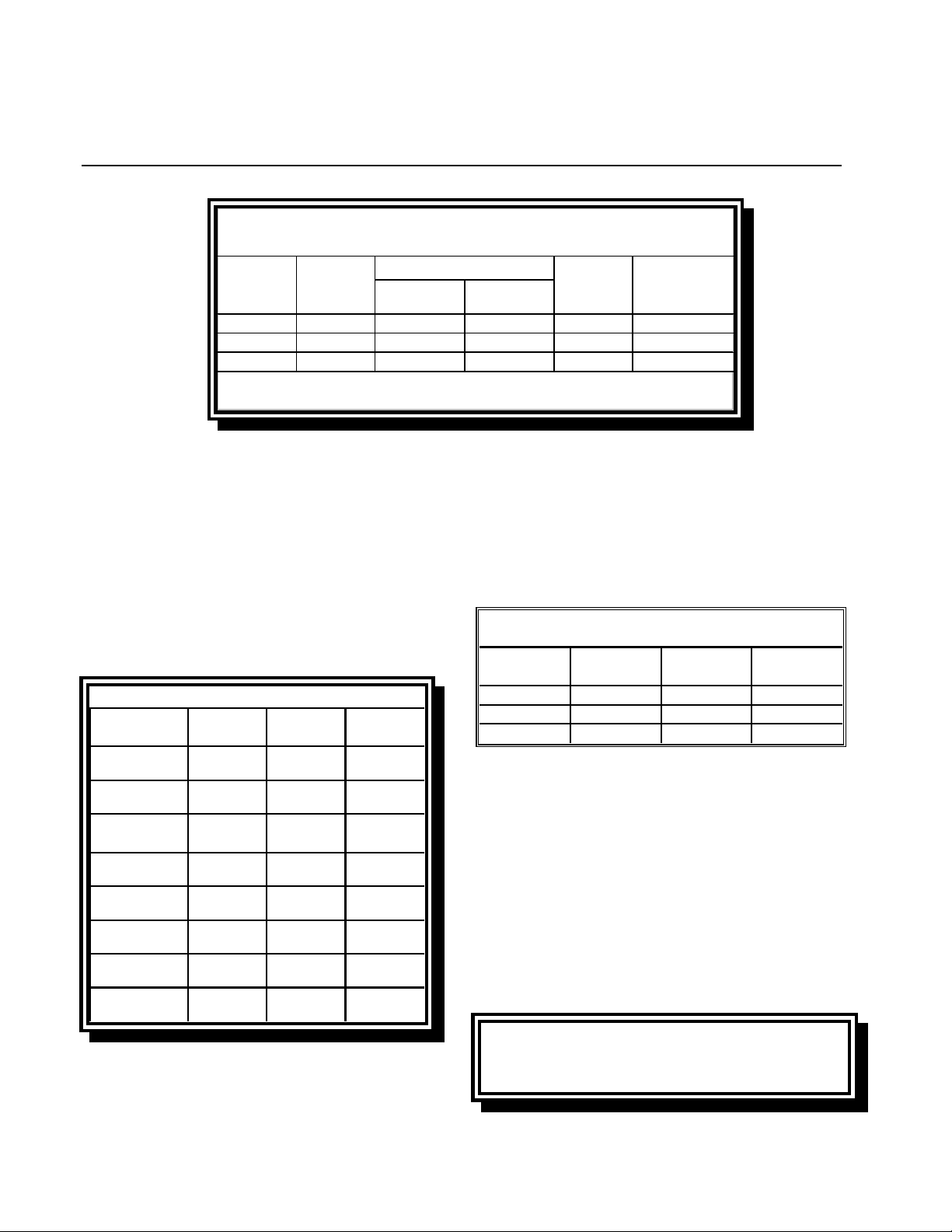
6. Verify the minimum and maximum gas
supply pressures for the type of gas to be
used in accordance with the accompanying
tables.
No n- C E S t andard
for Incoming Gas Pressures
Gas Minim um Maximum
Natural
LP
6" W.C.
1.49 kPa
14.93 mbar
11" W.C.
2.74 kPa
27.37 mbar
14" W.C.
3.48 kPa
34.84 mbar
14" W.C.
3.48 kPa
34.84 mbar
2-3
Page 12
47 SERIES GAS FRYERS
CHAPTER 2: INSTALLATION INSTRUCTIONS
CE Standard
for Incoming Gas Pre ssure s
Orifice Diameter
Pressure
Gas
G20 20 18 x 1,40 mm 18 x 1,30 mm 7,5 mbar 3 m
G25 20 - 25 18 x 1,40 mm 18 x 1,30 mm 10 mbar 3,5 m
G31 37 - 50 18 x 0,86 mm 18 x 0,80 mm 20,6 mbar 2,21 kg/h
(mbar)
Single
(1)
Vat
(1) mbar = 10,2 m m CE
Dual
Vat
Regulator
Pressure Consumption
3
/h
3
/h
7. For fryers equipped with a FootPrint III
system or basket lifts, plug the electrical
cord(s) into a power receptacle behind the
fryer.
2.4 Connection to Gas Line
The 47 Series fryer has received the CE mark
for the countries and gas categories indicated
in the accompanying table.
CE Approved Gas Categories
Pressure
Country Category Gas
BE
DE
DK-GR-IT
FR
LU
ES
NL
IE-PT-GB
I2E+(S)
I3P
I2 ELL
13P
I2 H G20 20
II2Esi3P
I2E G20/G25 20/25
II2H3P
II2L3P
II2H3P
G20/G25
G31
G20/G25
G31
G20/G25
G31
G20
G31
G25
G31
G20
G31
(mbar)
20/25
37
20
50
20/25
37 ET 50
20
37 ET 50
25
50
20
37
The size of the gas line used for installation is
very important. If the line is too small, the gas
pressure at the burner manifold will be low.
This may cause slow recovery and delayed
ignition. The incoming gas supply line should
be a minimum of 1½” (38 mm) in diameter.
Refer to the chart below for the minimum
sizes of connection piping.
Gas Connection Pipe Sizes
(Minimum incom i ng pi pe size should be 1 1/2" (38 mm))
4 or more
Gas Single Unit 2 - 3 Units
Natural
Propane 1/2" (13 mm) 3/4" (19 mm) 1" (25 mm)
Manufactured 1" (25 mm) 1 1/4" (33 mm) 1 1/2" (38 mm)
3/4" (19 mm)
1" (25 mm) 1 1/4" (33 mm)
units*
* For distances of more than 20 feet (6 m ) and/or
more than 4 fittings or elbows, increase the connection by one pipe size.
Before connecting new pipe to your unit, the
pipe must be thoroughly blown out to remove
any foreign particles. If these foreign particles
get into the burner and controls, they will
cause improper and sometimes dangerous operation.
CE Standard
Ensure airflow required for air combustion
supply is 2m3/h times kW.
2-4
Page 13
47 SERIES GAS FRYERS
CHAPTER 2: INSTALLATION INSTRUCTIONS
1. Connect the quick-disconnect hose to the
fryer quick-disconnect fitting under the
front of the fryer and to the building gas
line.
NOTE: Some fryers are configured for a
rigid connection to the gas supply line.
These units are connected to the gas supply line at the rear of the unit.
When using thread compound, use very
small amounts on male threads only. Use
a pipe thread compound that is not affected by the chemical action of LP gases
(Loctite™ PST56765 Sealant is one such
compound). DO NOT apply compound to
the first two threads. This will ensure that
the burner orifices and control valve do
not become clogged.
2. Open the gas supply to the fryer and check
all piping, fittings, and gas connections for
leaks. A soap solution should be used for
this purpose.
DANGER
Never use matches, candles, or any
other ignition source to check for
leaks.
If gas odors are detected, shut off the
gas supply to the fryer
at the main shut-off valve and contact
the local gas company or an
authorized service agency for service.
Out the Frypot” topics found in Chapter 3
of this manual.
WARNING
“Dry-firing” your unit will cause
damage to the frypot. Always ensure
that melted shortening, cooking oil, or
water and boil-out solution is in the
frypot before firing your unit for any
extended period.
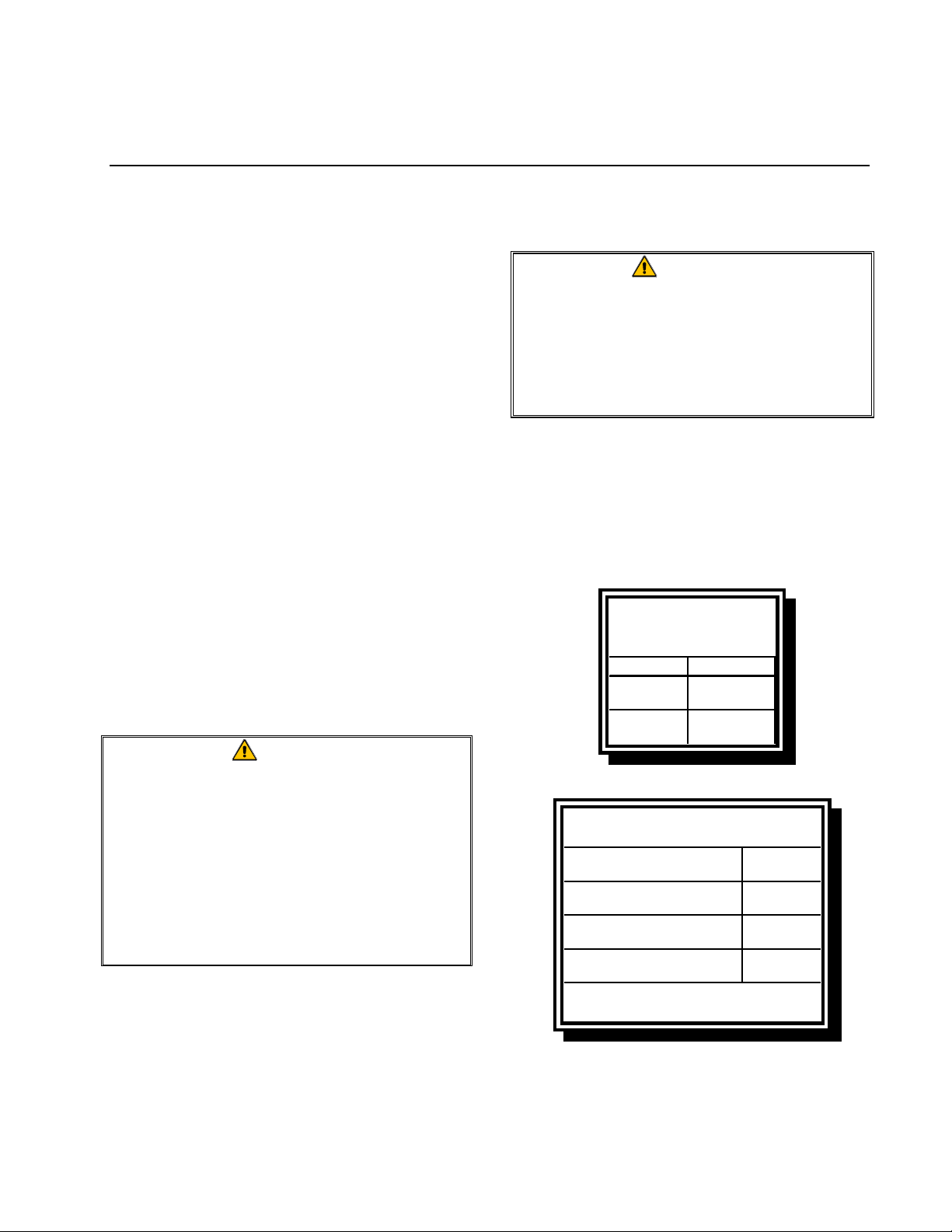
4. It is suggested that the burner manifold
pressure be checked at this time by the local gas company or an authorized service
agent. Refer to “Check Burner Manifold
Pressure” in Chapter 5 of this manual for
the proper procedure.
Non-CE Standard
Burner Manifold Gas
Pressures
Gas Pressure
Natural
LP
CE Standard
Burner Manifold Gas Pressures
Gas
Natural Gas Lacq
(G20) under 20 mbar
Natural Gas Gronique *
(G25) under 25 mbar
Propane
(G31) under 37 or 50 mbar
3.5" W.C.
0.8 kPa
8.25" W.C.
2.5 kPa
Pressure
(mbar)
8
10
21
3. Close the fryer drain valve and fill the fry-
pot with water and boil-out solution to the
bottom OIL-LEVEL line at the rear of the
frypot. Light the fryer and perform the
boil-out procedures that are described in
the “Lighting Instructions” and “Boiling
* Belgian G25 = 7,0 mbar
5. Check the thermostat calibration or com-
puter programmed temperature.
2-5
Page 14
47 SERIES GAS FRYERS
CHAPTER 2: INSTALLATION INSTRUCTIONS
• For units equipped with thermostat
controls, refer to the Thermostat Calibration instructions in Chapter 7.
• For units equipped with other types of
controllers, refer to the Set Point programming instructions in Chapter 3.
2.5 Converting to Another Gas Type
47 Series fryers are configured at the factory
for either natural gas or Propane (LP) gas.
A gas conversion kit must be installed by a
Factory Authorized Service Center technician
when converting from one type of gas to another.
DANGER
Switching to a different type of gas
without installing the proper conver-
sion kit may result in fire or explosion!
NEVER attach a fryer to a gas supply
for which it is not configured.
CE Gas Conversion Instructions
1. Between G20- and G25-type Natural Gas,
adjust the gas pressure at the regulator.
(Refer to the CE Standard Burner Manifold Gas Pressure Chart.) Do not change
the orifice.
2. Between a 2nd family gas (G20 or G25)
and a 3rd family gas (G31 Propane):
a. Change the orifices.
b. Change the pilot.
c. Change the gas valve regulator.
d. Adjust the manifold pressure.
3. Remove the rating plate and install a new
one. Call your local service agency or
KES for a new rating plate.
4. If the destination language changes, replace the labels. Call your local service
agency or KES for a label kit. The language of reference will be on the corner of
the label.
CE Gas Conversion Kits
Full Vat
Natural to LP: 826-1462 (includes .86mm orifice, P/N 810-
0340)
LP to Natural: 826-1463 (includes 1.40mm orifice, P/N 810-
0330)
Dual Vat
Natural to LP: 826-1464 (includes .80mm orifice, P/N 810-
1040)
LP to Natural: 826-1465 (includes 1.30mm orifice, P/N 810-
0131)
2-6
Non-CE Gas Conversion Kits
Contact
to determine the specific gas conversion
components required for this equipment.
Frymaster
at 1-800-551-8633
Page 15
CHAPTER 3: OPERATING INSTRUCTIONS
N
n
)
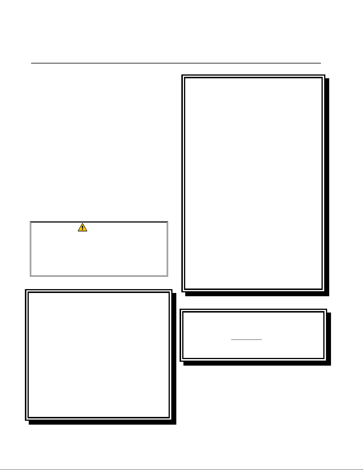
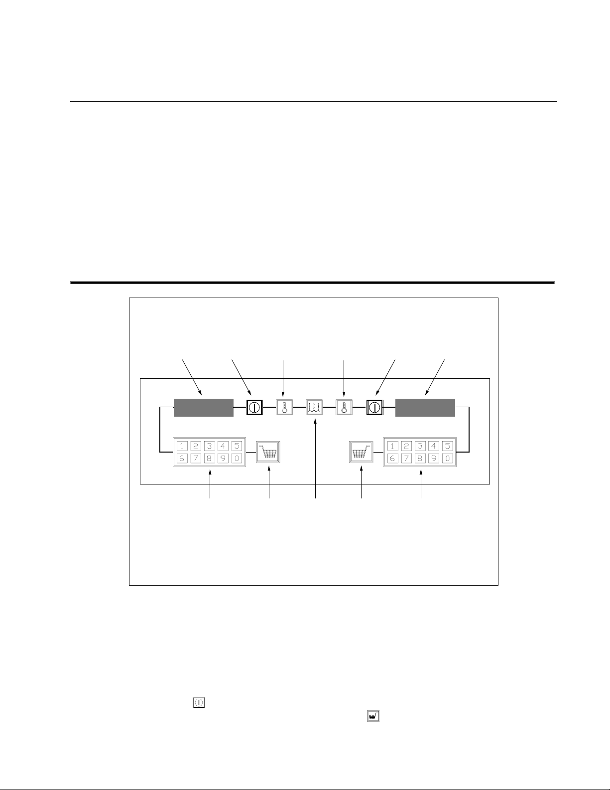
FINDING YOUR WAY AROUND THE 47 SERIES FRYER
Gas Valves
Control Panel (CM III
Computer show
47 SERIES GAS FRYERS
Flue Cap
Flue
Power Shower
Basket Hanger
Wiring Diagrams
Fryer Identification Data
Labels (Model and Serial
umber)
Drain and Filter Control Handles.
FootPrint III Built-in Filtration Unit
3-1
Page 16
47 SERIES GAS FRYERS
CHAPTER 3: OPERATING INSTRUCTIONS
3.1 Start-Up Procedure
CAUTION
If this is the first time the fryer is being
used after installation, refer to Section
3.2, Boil-Out Procedure.
CAUTION
The cooking oil/shortening capacity of
the 47 Series fryer is 50 lbs (25 liters)
at 70ºF (21ºC) for a full pot and 25 lbs
(12.5 liters) at 70ºF (21ºC) for each half
of a split pot.
Before lighting the fryer, make sure the
fryer is OFF and the frypot drain
valve(s) is/are closed. Remove the
basket support rack(s), if installed,
and fill the frypot to the bottom
OIL-LEVEL line.
If solid shortening is being used,
make sure it is packed down into
the bottom of the frypot.
For units equipped with Pilot Systems, the
pilot must be manually lit before the fryer
can be placed into operation. The pilot on
fryers with Electronic Igni tion is automatically lit when the unit is turned on.
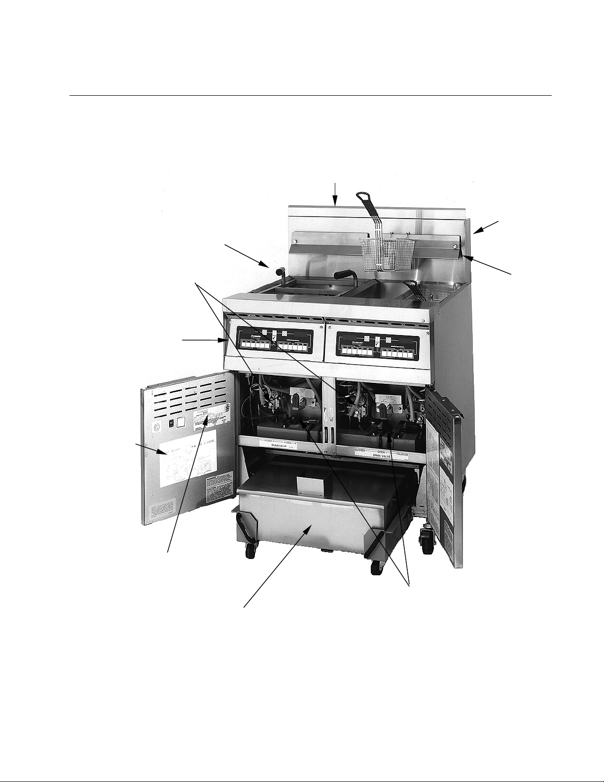
Lighting the Robertshaw Valve Pilot:
1. Ensure power to the unit is OFF.
2. Turn the gas valve knob to the OFF posi-
tion. Wait 5 minutes, then turn the knob
to the PILOT position.
Knob is shown in
OFF position.
Note index mark.
3. Place a flame near the pilot assembly, push
and hold the knob in, light the pilot, and
continue to depress the knob for at least 60
seconds after the pilot lights. Failure to
hold the knob in long enough will cause
the pilot to go out when the knob is released. If the pilot goes out when the knob
is released, wait at least 5 minutes then repeat this step.
4. Turn the gas valve knob to the ON position.
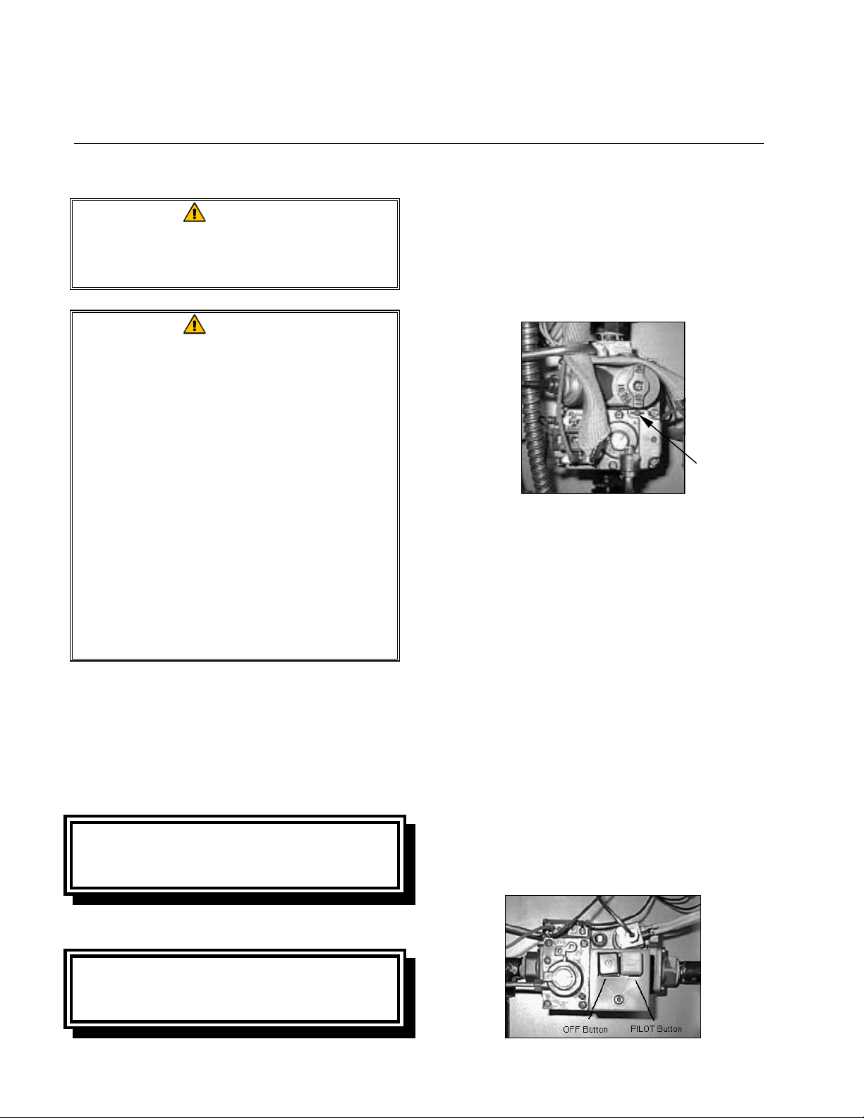
Lighting the Honeywell Valve Pilot:
Non-CE Standard
Units configured to Non-CE standards are
equipped with Robertshaw valves.
CE Standard
Units configured to CE standards are
equipped with Honeywell valves.
1. Ensure power to the unit is OFF.
2. Press the OFF (red) button. Wait 5 minutes.
3-2
Page 17
47 SERIES GAS FRYERS
CHAPTER 3: OPERATING INSTRUCTIONS
3. Place a flame near the pilot assembly, push
and hold the PILOT (white) button in,
light the pilot, and continue to depress the
button for at least 60 seconds after the pilot lights. Failure to hold the knob in long
enough will cause the pilot to go out when
the knob is released. If the pilot goes out
when the knob is released, wait at least 5
minutes then repeat this step.
Placing the Fryer into Operation.
For units equipped with Thermostat
Controls:
Place the Melt Cycle switch (if equipped)
to the ON position and set the thermostat
knob to the desired cooking temperature.
The U-shaped burner should “light-off”
and burn with a strong, blue flame.
unit will automatically switch to the
Heating mode. The burner will remain lit
until the frypot temperature reaches the
programmed cooking temperature (setpoint).
3.2 Boiling-Out the Frypot
To ensure that the frypot is free of any contamination resulting from its manufacture,
shipping, and handling during installation, the
frypot must be boiled out before first use.
Frymaster recommends boiling out the frypot
each time the oil or shortening is changed.
DANGER
Never leave the fryer unattended
during the boil-out process. If the boil-
out solution boils over, turn off power
to the fryer immediately and let the
solution cool for a few minutes before
resuming the process.
CAUTION
The fryer will stay in the Melt Cycle
mode until the Melt Cycle Switch is
placed in the OFF position.
For units equipped with other than
Thermostat Controls:
Place the computer/controller ON/OFF
switch in the ON position and set the
thermostat to—or program the controller
for—the desired cooking temperature, referred to as the setpoint. The U-shaped
burner should “light off” and burn with a
strong, blue flame. The unit automatically
enters the Melt Cycle mode if the frypot
temperature is below 180ºF (82ºC).
(NOTE: During the melt cycle, the burner
will repeatedly fire for a few seconds, then
go out for a longer period.) When the frypot temperature reaches 180ºF (82ºC), the
1. Before lighting the burner, close the fryer
drain valve(s) and fill the frypot to the
bottom OIL-LEVEL line with a mixture of
cold water and Frymaster™ FRYER ‘N’
GRIDDLE cleaner or detergent.
2. For units equipped with other than Com-
puter Magic III controllers or Solid-State
Basket Lift Timers, set the thermostat to,
or program the controller for, 200ºF
(93ºC).
For units equipped with Computer Magic
III controllers, select the Boil-Out feature
in accordance with the procedure Using
the Boil-Out Feature on page 3-7.
For units equipped with Solid-State Basket
Lift Timers, press the Boil-Out Mode button
to begin the boil-out process.
3-3
Page 18
47 SERIES GAS FRYERS
CHAPTER 3: OPERATING INSTRUCTIONS
3. Place the fryer into operation in accor-
dance with Section 3.1.
4. Simmer the solution for 1 hour.
5. After the solution simmers for 1 hour, turn
the fryer off, allow the solution to cool,
then add 2 gallons (7.75 liters) of cold
water and stir. Drain the solution into a
suitable container and clean the frypot
thoroughly.
WARNING
Do not drain boil-out solution into
the built-in filtration system. Doing
so may cause damage to the
filtration pump.
6. Rinse the frypot at least twice by filling the
frypot with clean water and draining. Dry
the frypot thoroughly with a clean, dry
towel.
3.3 Shutting the Fryer Down
For short-term shut down during the workday,
place the fryer power switch in the OFF position and put the frypot covers in place (if the
fryer is so equipped).
When shutting the fryers down at closing time,
place the fryer power switch in the OFF position, place the gas valve in the OFF position,
and put the frypot covers in place (if the fryer
is so equipped).
3.4 Controller Operation and Programming
Fryers in the 47 Series can be equipped with
any of the following types of controlling devices:
• Computer Magic III
• Thermostat Controller (with or without
Manual Basket Lift Timers)
DANGER
Remove all drops of water from the
frypot before filling with cooking
oil/shortening. Failure to do so may
cause spattering of hot liquid when
the oil/shortening is heated to
cooking temperature.
• Analog Controller (with or without Man-
ual Basket Lift Timers)
• Digital Controller (with or without Manual
Basket Lift Timers)
• Basket Lift Timer
Each type is discussed in detail in the following pages.
3-4
Page 19
N
OTE:
Some computers
may have this
earlier style
ON/OFF Switch:
ON
OFF
47 SERIES GAS FRYERS
CHAPTER 3: OPERATING INSTRUCTIONS
1 234 5
c y c l c y c l
Frymaster
L1 2 3445
6 78
6
COMPUTER MAGIC
78 9
0R
COMPUTER MAGIC III
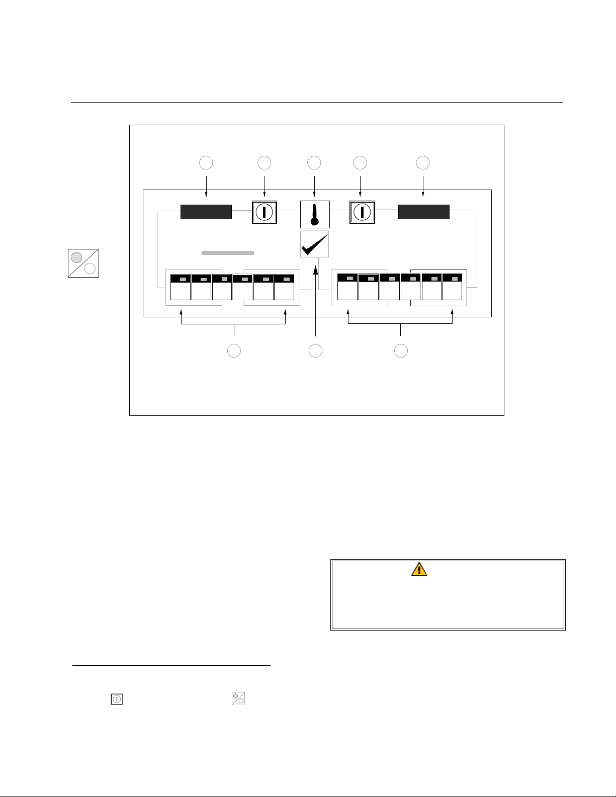
COMPUTER MAGIC III CONTROLLER
The Computer Magic III control panel includes the following items:
1/2. Left and Right LED Displays
1/3. Temperature Check and Program Lock
Switch
4/5. Left and Right Frypot Power Switches
NOTE: On single vat units, either
switch will turn the fryer on and off.
6/7. Left and Right Product Selection and
Coding Keys
1/8. Program Mode Switch
COMPUTER OPERATING INSTRUCTIONS
Turn the computer on by pressing the Power
Switch (or ON/OFF Switch
ON
OFF
). NOTE:
A decimal between digits 1 and 2 in either
LED Display indicates that the burner is on.
1. One of the following will be displayed:
a. cycl
cycl, indicating that the fryer is oper-
cyclcycl
ating in the melt cycle mode. The
fryer will remain in the melt cycle
mode until it reaches 180ºF (82ºC) or
is canceled manually by pressing the R
key.
CAUTION
Do not cancel the melt cycle mode
until solid shortening is completely
melted.
b. hi
hi, indicating that the frypot tempera-
hihi
ture is 21ºF (12ºC) higher than the setpoint.
c. LO
LO, indicating that the frypot tempera-
LOLO
ture is 21ºF (12ºC) lower than the setpoint.
3-5
Page 20
47 SERIES GAS FRYERS
CHAPTER 3: OPERATING INSTRUCTIONS
d. “- - - -,” indicating that the frypot tem-
perature is in the cooking range.
NOTE: For best results, cooking
should not be attempted unless the display indicates “- - - -.”
e. help
help, indicating a heating problem.
helphelp
f. hot
hot, indicating the frypot temperature
hothot
is in excess of 410ºF (210ºC).
g. prob
prob, indicating that the computer has
probprob
detected a problem in the temperature
measuring and control circuits.
1. Press a product switch to initiate a cook
cycle.
a. The basket lift (on fryers so equipped)
will lower the product into the frypot.
b. The display will indicate the previ-
ously programmed cook time and begin countdown.
c. If shake time is programmed, the op-
erator will be notified of the need to
shake the product “X” seconds after
the cook cycle has begun (X = amount
of time programmed). An alarm will
sound, and the display will read SH#
SH#,
SH#SH#
where “#” will be the switch number.
If no shake time has been programmed,
sh#
sh# will not appear during the cook
sh#sh#
cycle. The alarm is self-canceling.
d. At the end of the cooking cycle, an
audible alarm will sound, cooc
cooc will be
cooccooc
displayed, and the associated product
switch indicator will flash. To cancel
the cook alarm, press the appropriate
switch.
e. At this time, the hold time will be dis-
played (if programmed greater than
zero), and the countdown will begin.
When the countdown reaches zero,
hD_
hD_ will be displayed and an alarm
hD_hD_
will sound. The blank will be the
switch number. The hold alarm is canceled by pressing the Programming
Switch . NOTE: If the display is in
use, the hold time countdown will not
be displayed.
2. To check the frypot temperature at any
time, press the Temperature Check Switch
once. To check the setpoint, press the
switch twice. If you suspect the temperature probe is defective, check the temperature of the frypot with a thermometer
or pyrometer to verify that the computer
readout is reasonably close to the measured reading.
4. During idle periods when the fryer is on
but not in use, “- - - -” should appear in
both displays. If not, check the actual
temperature and setpoint.
CAUTION
The electronic circuitry in your
computer can be affected adversely by
current fluctuations and electrical
storms. Should it fail to function or
program properly for no apparent
reason, the computer should be reset
by unplugging the computer and
plugging it back in. This could prevent
a service call.
COMPUTER PROGRAMMING INSTRUCTIONS
1. Turn the computer on by pressing the
Power
Switch (or ON/OFF
ON
OFF
Switch).
3-6
Page 21

47 SERIES GAS FRYERS
CHAPTER 3: OPERATING INSTRUCTIONS
2. Enter the programming mode by pressing
the Program Mode Switch . Code
appear in the left display. If you enter the
programming mode by mistake, press the
switch again to exit the programming
mode. NOTE: If you try to enter the programming mode while the computer is
cooking, the display will flash busy
3. Enter the number 1 6 5 0 by pressing the
number keys. Unless this code is entered,
programming will not be accepted. This is
to prevent unauthorized persons from
changing your current instructions.
4. sp-
sp-r (Setpoint) will appear in the left dis-
sp-sp-
play. Any previously programmed temperature setpoint will appear in the right
display. To change the setpoint, enter the
desired setpoint temperature using the
number keys. For CE units, the highest
setpoint allowed is 370ºF (188ºC). For
Non-CE units the number is 375ºC
(191ºC). Press the Program Mode Switch
to lock in the new setpoint (or the old
setpoint, if it was not changed). If the unit
is a dual vat fryer, sp-L
lowing the setpoint for the left vat to be
adjusted or confirmed.
5. selp
selp (Select Product) will appear in the
selpselp
left display. Press the product button to be
programmed (or press to return to the
normal operating mode).
6. sens
sens (Sensitivity) appears in the left dis-
senssens
play. Any previously programmed sensitivity setting will appear in the right display. To change the sensitivity setting,
enter the new setting and press
in. If the setting was not changed, pressing
accepts the previous setting.
sp-L will appear, al-
sp-Lsp-L
Code will
CodeCode
busy.
busybusy
to lock it
Sensitivity is a built-in feature that adjusts
cooking time to compensate for the drop in
frypot temperature when a basket of product is placed into it. Different food products will vary in density, basket load size,
and initial temperature. Food products
will also vary in how well cooked a product is required to be. A proper sensitivity
setting for each product will assure a
high-quality product each time. For example: four ounces of fries can be programmed to be cooked to the same quality
as two and one-half pounds. Some experimenting with the range of 0 - 9 (0 being least sensitive and 9 being most sensitive) may be required to obtain the desired
quality to meet your specifications, but
setting 5 is the recommended starting
point.
7. cooc
cooc (Cook Time) will now show in the
cooccooc
left display. Any previously programmed
cooking time will appear in the right dis-
play. Pressing will accept the current
cooking time. To change the cooking
time, enter the new time using the Number
keys. Press
8. sh_
sh_ (Shake Time) appears in the left dis-
sh_sh_
play. If your product requires shaking
during the cooking process, set the number
of minutes to cook before shaking using
the number keys.
For example, entering “30” means the
product needs to be shaken after it has
been cooking for 30 seconds. At the end
of one minute, an alarm will sound and the
product switch will flash for 3 seconds. If
your product does not require shaking,
enter “0”. The number entered will appear
in the right display. Press
programmed time.
to lock in the new time.
to lock in the
3-7
Page 22
47 SERIES GAS FRYERS
CHAPTER 3: OPERATING INSTRUCTIONS
9. hd_
hd_ (Hold Time) will appear in the left
hd_hd_
display. Set the time the product may
be held before serving, anything from
13 seconds to 60 minutes. If you do
not wish to use the hold time feature,
enter 0. Press
to lock in the time.
In the event the same product is being
cooked in more than one basket, any product button can be programmed to use the
hold timer normally used with a different
product button. Example: Program button 3 for 7:00 minutes hold time. Then,
when programming button R for hold time,
press product button 4. Both product
button 3 and product button R will then
use the same hold time of 7:00 minutes.
The button numbers and their assigned
address numbers are:
Button: L 1 2 3 4 5 6 7 8 9 0 R
Address: 1 2 3 4 5 6 7 8 9 10 11 12
10. selp
selp (Select Product) will again appear in
selpselp
the left display. If more products are to be
programmed, return to Step 5 and follow
all instructions to this point, repeating for
each product.
11. When you complete your programming,
lock in the whole program by pressing the
Temperature Check/Program Lock Switch
.
USING THE BOIL-OUT FEATURE
CAUTION
Before using this feature, ensure the
frypot is filled with a mixture of cold
water and Frymaster™ FRYER ‘N’
GRIDDLE cleaner or detergent.
1. To program the fryer for boil-out, press the
Power Switch (or ON/OFF
ON
OFF
Switch)
followed by the Program Mode Switch .
Code
Code will appear in the left display.
CodeCode
2. Enter the code number 1 6 5 3. The right
display will read boil
boil. The temperature is
boilboil
automatically set for 195ºF (91ºC). The
fryer will attain this temperature and remain there until the Power (or ON/OFF
ON
OFF
) Switch is pressed, which cancels the
boil-out mode. In high-altitude locations,
the fryer must be monitored constantly for
boil-over conditions. If boil-over occurs,
turn off the fryer immediately, allow it to
cool, then re-enter the boil-out mode to
continue the boil-out process.
FRYER RECOVERY TIME CHECK FEATURE
1. The computer automatically checks the
recovery time each time the frypot temperature drops below 250ºF (121ºC). To
check recovery time, press the Program
Mode Switch . Code
Code will appear in the
CodeCode
left display.
2. Enter the code number 1 6 5 2 on the number keypad. The recovery time will appear
in both displays for 5 seconds.
SELECTING FAHRENHEIT– CELSIUS DISPLAY
MODE
1. The computer can display temperatures in
either Fahrenheit or Celsius. To change
from one to the other, press the Program
. Code
Mode Switch
Code will appear in the
CodeCode
left display.
2. Enter the code number 1 6 5 8 on the number keypad. The computer will toggle the
temperature display from Celsius to Fahrenheit or from Fahrenheit to Celsius.
3-8
Page 23
47 SERIES GAS FRYERS
CHAPTER 3: OPERATING INSTRUCTIONS
3. Press the Temperature Check/Program
Lock Switch to display the temperature
in the newly selected mode.
SELECTING FRYPOT TEMPERATURE DISPLAY
MODE
1. To display the actual frypot temperature at
all times, press the Program Mode Switch
. Code
Code will appear in the left display.
[[[[
CodeCode
Frym as te r
2. Enter code 1 6 5 L using the number key-
pads. The computer will display the actual
frypot temperature. NOTE: During the
product cooking process, the cooking time
will not be displayed, but timing is taking
place.
3. To return to setpoint display, repeat Steps
1 and 2.
Heat
ON/OFF
Switch
2
ON
OFF
Mode
Light
3
Temperature
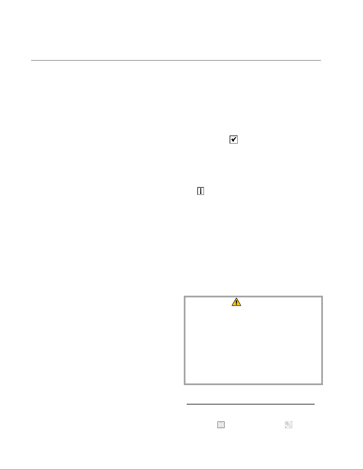
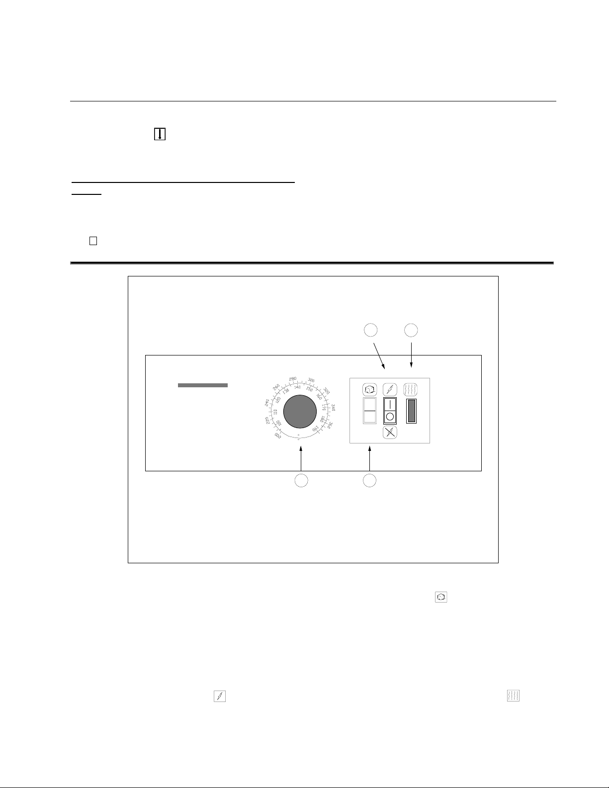
THERMOSTAT CONTROLLER
THERMOSTAT CONTROLLER
The Thermostat Controller utilizes a frypot
thermostat that is directly connected to a temperature knob mounted on the control panel.
Rotating the knob to the desired cooking temperature (setpoint) physically adjusts the thermostat control at that temperature. Placi ng the
ON/OFF Switch in the ON position supplies power to the fryer’s components and
C
F
1
Knob
4
Melt Cycle
Switch
causes the switch to illuminate. Placing the
Melt Cycle Switch
in the ON position
causes the fryer burner to repeatedly cycle on
for a few seconds and off for a longer period.
The purpose is to gradually melt solid shortening to prevent scorching, and to prevent
creation of “hot spots” on the frypot. This
switch is also illuminated when in the ON position. The Heat Mode Indicator illuminates when the frypot is below setpoint.
3-9
Page 24
47 SERIES GAS FRYERS
CHAPTER 3: OPERATING INSTRUCTIONS
Other than setting the thermostat knob to the
desired cooking temperature, the Thermostat
Controller requires no programming. However, it does require calibration. Refer to Section 7.7, Calibrating the Thermostat Controller, for the procedure to be followed.
On
Heat
Mode
Light
Power
Light
Frym as te r
CAUTION
The fryer will remain in the Melt Cycle
mode until turned off by placing the
Melt Cycle Switch in the OFF position.
Melt
Trouble
Light
C
F
Cycle
Light
?
SOLID STATE
Power
Switch
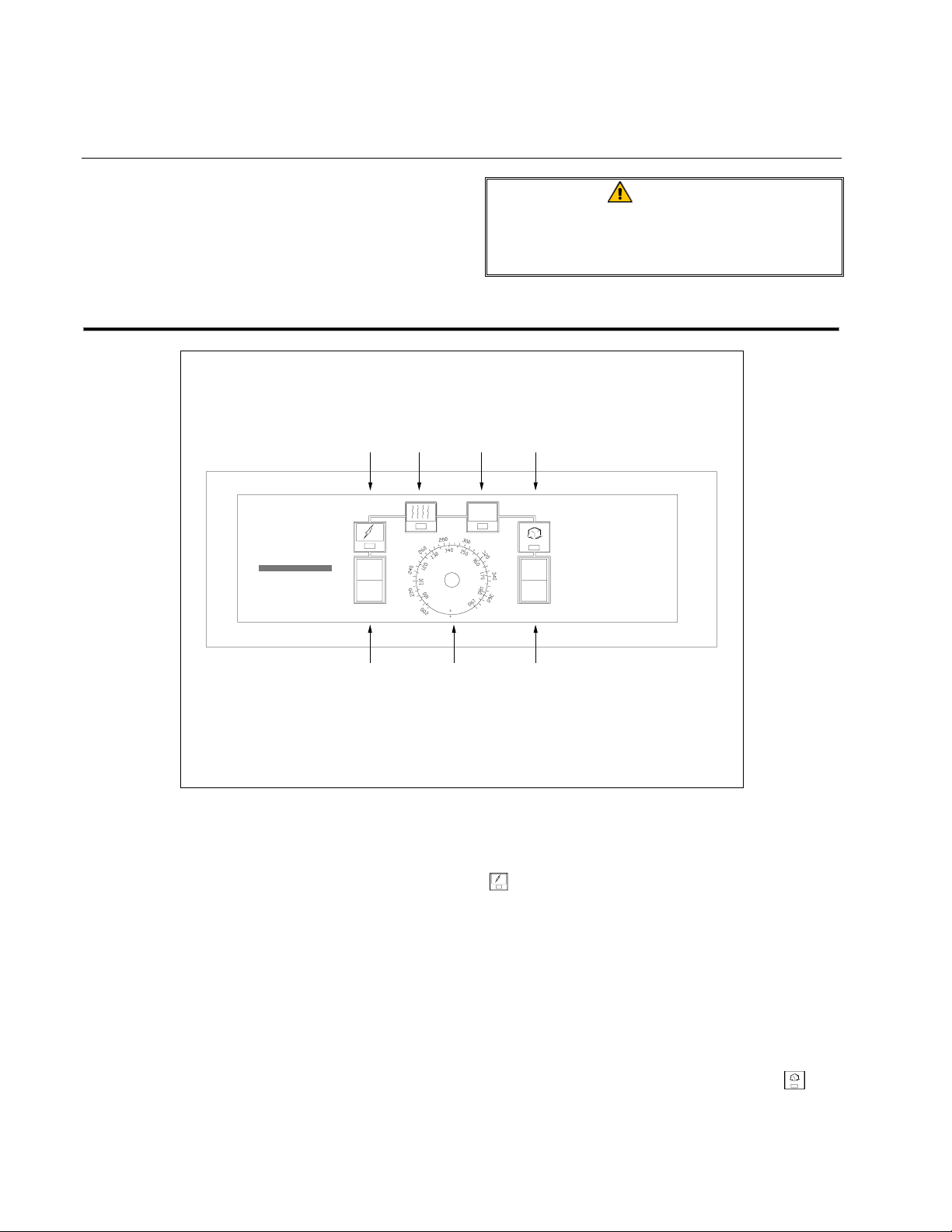
ANALOG CONTROLLER
ANALOG CONTROLLER
Temperature
In units equipped with analog controllers, the
frypot thermostat has been replaced with a
solid-state temperature probe and solid-state
electronics mounted on the control panel, reducing the number of moving parts and eliminating the need to calibrate the thermostat.
The temperature probe is connected to the
control circuitry via an interface board behind
the control panel.
The cooking temperature setpoint is set by rotating the Temperature Knob to the desired
temperature.
Knob
Melt Cycle
Switch
When the Power Switch is placed in the ON
position, electrical current is supplied to the
fryer’s components and the Power On Light
illuminates.
Placing the Melt Cycle Switch in the ON
position causes the burner to cycle on for a
few seconds and off for a longer period until
the temperature in the frypot reaches 180ºF
(82ºC). At that time the unit automatically
enters the heat mode, causing the burner to
remain lit until the setpoint is reached. When
in the melt cycle, the Melt Cycle Light
will
alternately illuminate and go out as the burner
cycles on and off. When the unit enters the
3-10
Page 25
47 SERIES GAS FRYERS
CHAPTER 3: OPERATING INSTRUCTIONS
heat mode, the Heat Mode Light
will
illuminate and remain on until the setpoint is
reached.
For units equipped with electronic ignition,
the Trouble Light
?
will illuminate if there is
an ignition failure. To reset the controller after
ON/OFF
Switch
9 . 9 9 9
Frym as te r
Digital
Display
an ignition failure, place the Power switch in
the OFF position for 30 seconds, then place it
back in the ON position.
For all units, the Trouble Light also indicates
that there is a probe circuit or high limit circuit
problem.
Celcius or
Fahrenheit
Display Switch
Temperature
or Setpoint
Display Switch
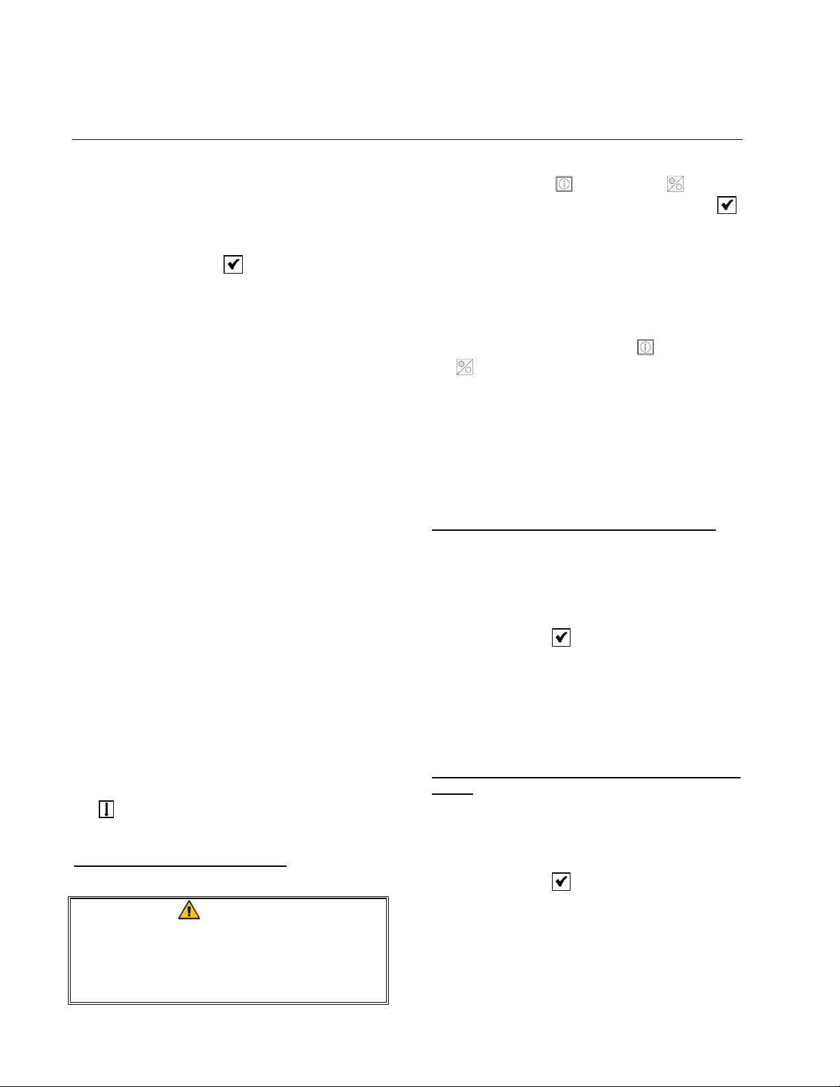
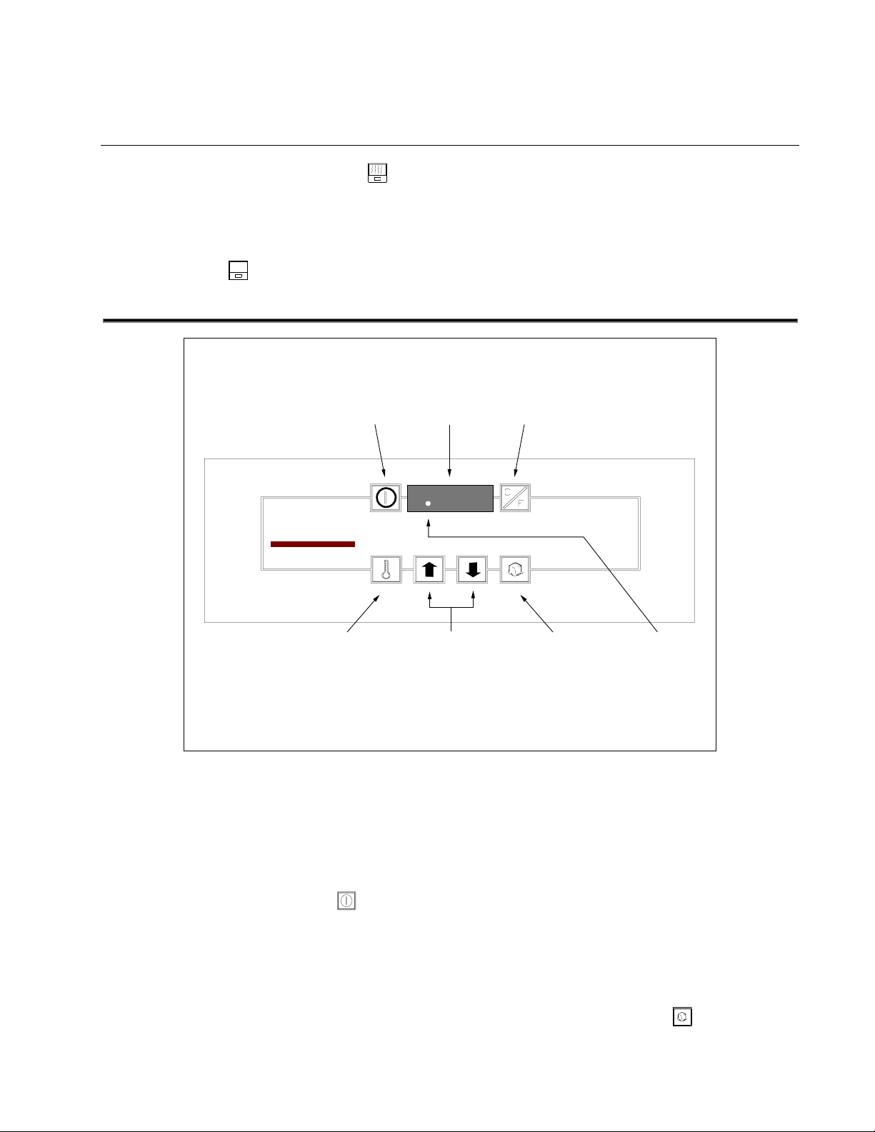
DIGITAL CONTROLLER
DIGITAL CONTROLLER
As with the analog controller, the frypot thermostat has been replaced with a solid-state
temperature probe and solid-state electronics
mounted on the control panel.
Pressing the ON/OFF Switch
supplies
electrical power to the fryer, and causes the
controller software version number to display
for 4 seconds in the Digital Display.
Following the display of the software version
number, the setpoint temperature will display
constantly. Pressing the Temperature/Setpoint
Setpoint
Adjustment
Arrows
Melt
Cycle
Switch
Heating
Mode
Indicator
Display Switch will display the actual frypot
temperature.
The fryer will automatically enter the melt
cycle mode and will continue to cycle on for a
few seconds and off for a longer period until
the temperature in the frypot reaches 180ºF
(82ºC). At that time, it will enter the heat
mode. The purpose of the melt cycle is to
gradually melt solid shortening to prevent its
scorching, and to prevent creation of “hot
spots” on the frypot. To cancel the melt cycle,
press the Melt Cycle Switch .
3-11
Page 26
47 SERIES GAS FRYERS
CHAPTER 3: OPERATING INSTRUCTIONS
CAUTION
Do not cancel the Melt Cycle if solid
shortening is being used.
NOTE: If solid shortening is not being used,
the controller can be programmed to bypass
the Melt Cycle as follows:
1. With the controller in the OFF mode, press
the Melt Cycle Switch . The display
will show either a “0” (meaning that the
melt cycle can be bypassed) or a “1”
(meaning thant the melt cycle cannot be
bypassed).
2. To change the bypass option setting, press
and hold the Melt Cycle Switch for 5 to
6 seconds to toggle the “0” to “1” or vice
versa. When the display shows the desired
setting, release the switch.
The fryer will remain in the heat mode until
the setpoint is reached. The Heat Mode Indicator is a decimal point that appears between
the first two numbers of the digital display to
indicate the unit is heating. When the setpoint
is reached, the decimal will go out, indicating
the fryer is ready for cooking.
To enter or change the setpoint temperature,
press the Up Arrow or Down Arrow keys to
raise or lower the temperature setting. The
display will change at a rate of about 1 degree
per second for approximately the first 12 degrees, then change to a faster rate if the arrow
is continuously pressed.
The temperature can be displayed in either
Fahrenheit or Celsius. To change from one to
the other, press the C/F Switch .
Frym as te r
ON
OFF
C
F
Basket Lift
Timers
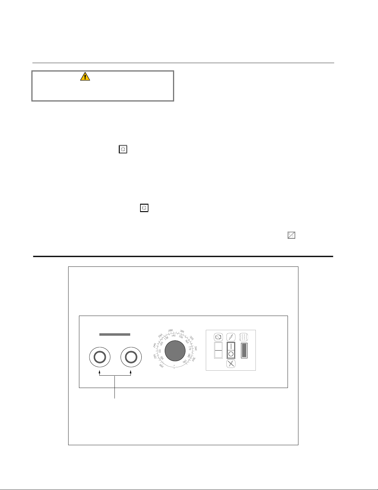
THERMOSTAT CONTROLLER with MANUAL BASKET LIFT TIMERS
3-12
Page 27
47 SERIES GAS FRYERS
CHAPTER 3: OPERATING INSTRUCTIONS
MANUAL BASKET LIFT TIMER
The Manual Basket Lift Timer (shown on the
preceding page) is not a fryer controller. It
only allows the operator to select a cooking
time and initiate independent cooking cycles
for each basket. It is available with the Thermostat Controllers, Analog Controllers, and
Digital Controllers. Computer Magic III and
the Basket Lift Timer control both the basket
lifts and the fryer.
Digital
Display
ON/OFF
Button
Temperature
Check Button
The cooking time for a basket is specified by
rotating the corresponding timer knob to the
desired time. Pressing the center of the knob
initiates the cooking cycle. The basket will be
automatically lowered into the frypot, and the
timer will begin to count down. When the
timer reaches zero, an alarm buzzer will sound
briefly to alert the operator that the cooking
cycle is completed, and the basket will then be
automatically raised from the frypot. A new
cycle is started by pressing the knob again.
T emperature
Check Button
ON/OFF
Button
Digital
Display
Cook Time
Programming
Buttons
SOLID-STATE BASKET LIFT TIMER
Left
Basket
Button
BASKET LIFT TIMER
The Basket Lift Timer allows the operator to
specify individual cooking times for each vat
and independently control the operation of
each basket lift.
Pressing the ON/OFF buttons supplies
electrical power to the fryer components. The
Boil-Out
Button
3-13
Right
Basket
Button
Cook Time
Programming
Buttons
fryer will automatically go into the melt cycle
mode if the temperature in the frypot is below
180ºF (82ºC), cycling on for a few seconds
and off for a longer period. The purpose of
the melt cycle is to gradually melt solid shortening to prevent its scorching, and to prevent
the creation of “hot spots” in the frypot. To
cancel the melt cycle mode, press the Right
Basket
button.
Page 28

47 SERIES GAS FRYERS
CHAPTER 3: OPERATING INSTRUCTIONS
The cook time for each basket is always
shown in the Digital Displays except when the
Temperature Check buttons are pressed.
To change a cook time, enter the new time
with the number keys.
To view the setpoint for a frypot, press the
corresponding Temperature Check button .
The setpoint for the frypot will be shown in
the corresponding Digital Display. NOTE:
For full pot (single vat) units, the setpoint
will be shown in the right display only.
To change the setpoint, enter the new temperature using the number keys, then press the
Temperature Check button again to lock in
the setpoint and return to the cook time mode.
Pressing a Basket button initiates a cooking
cycle. The basket is automatically lowered
into the frypot and the cook time in the Digital
Display begins to count down. When the
countdown reaches zero, the basket is raised
from the frypot and a buzzer sounds to alert
the operator that cooking is completed.
Pressing the Basket button silences the
alarm.
The controller also displays the following
trouble messages in the Digital Display of the
vat functioning abnormally:
• HELP
HELP is displayed continuously if there is a
HELPHELP
heating failure.
• hot
hot is displayed if the frypot temperature
hothot
rises above 385ºF (196ºC).
• PROB
PROB indicates a problem with the tem-
PROBPROB
perature probe circuit.
3-14
Page 29
47 SERIES GAS FRYERS
CHAPTER 4: FILTRATION INSTRUCTIONS
4.1 Draining and Manual Filtering
DANGER
Allow oil/shortening to cool to 100ºF
(38ºC) or lower before draining to an
appropriate container for disposal.
If your fryer is not equipped with the built-in
Foo t P r int III F iltration System, the cooking oil
or shortening must be drained into another
suitable container. FOR SAFE, CONVENIENT
DRAINING AND DISPOSAL OF USED COOKING
OIL OR SHORTENING,
MENDS USING THE
DISPOSAL UNIT (SDU). THE SDU IS AVAILABLE
THROUGH YOUR LOCAL DISTRIBUTOR
Frymaster RECOM-
Frymaster™ SHORTENING
.
1. Turn the fryer power switch to the OFF
position. Screw the drainpipe (provided
with your fryer) into the drain valve.
Make sure the drainpipe is firmly screwed
into the drain valve and that the opening is
pointing down.
2. Position a metal container with a sealable
cover under the drainpipe. The metal
container must be able to withstand the
heat of the cooking oil/shortening and hold
hot liquids. If you intend to reuse the oil
or shortening, Frymaster recommends
that a
Frymaster™ filter cone holder and
filter cone be used when a filter machine is
not available. If you are using a Frymaster
filter cone holder, be sure that the cone
holder rests securely on the metal container.
3. Open the drain valve slowly to avoid
splattering. If the drain valve becomes
clogged with food particles, use the
Fryer’s Friend (poker-like tool) to clear the
blockage.
DANGER
DO NOT insert anything into the drain
from the front to unclog the valve. Hot
oil/shortening will rush out, creating an
extreme hazard.
WARNING
DO NOT hammer on the drain valve
with the Fryer’s Friend. This will
damage the drain valve ball and
prevent the valve from sealing
securely, resulting in a leaky valve.
4. After draining the oil/shortening, clean all
food particles and residual oil/shortening
from the frypot. BE CAREFUL, this material may still cause severe burns if it
comes in contact with bare skin.
5. Close the drain valve securely and fill the
frypot with clean, filtered or fresh cooking
oil or solid shortening to the bottom OIL-
LEVEL line.
DANGER
When using solid shortening, pack the
shortening down into the bottom of the
frypot. DO NOT operate the fryer with
a solid block of shortening sitting in
the upper portion of the frypot. This
will cause damage to the frypot and
may cause a flash fire.
4.2 FootPrint III Filtration System
Operation
The Foot Pri nt III F iltration System allows the
cooking oil or shortening in one frypot to be
safely and efficiently filtered while the other
frypots in a battery remain in operation.
4-1
Page 30
47 SERIES GAS FRYERS
CHAPTER 4: FILTRATION INSTRUCTIONS
The overwhelming majority of reported problems with the Foot Print III system have been
found to be the result of improper operation.
Careful attention to the step-by-step instructions that follow will ensure that your system
operates as intended.
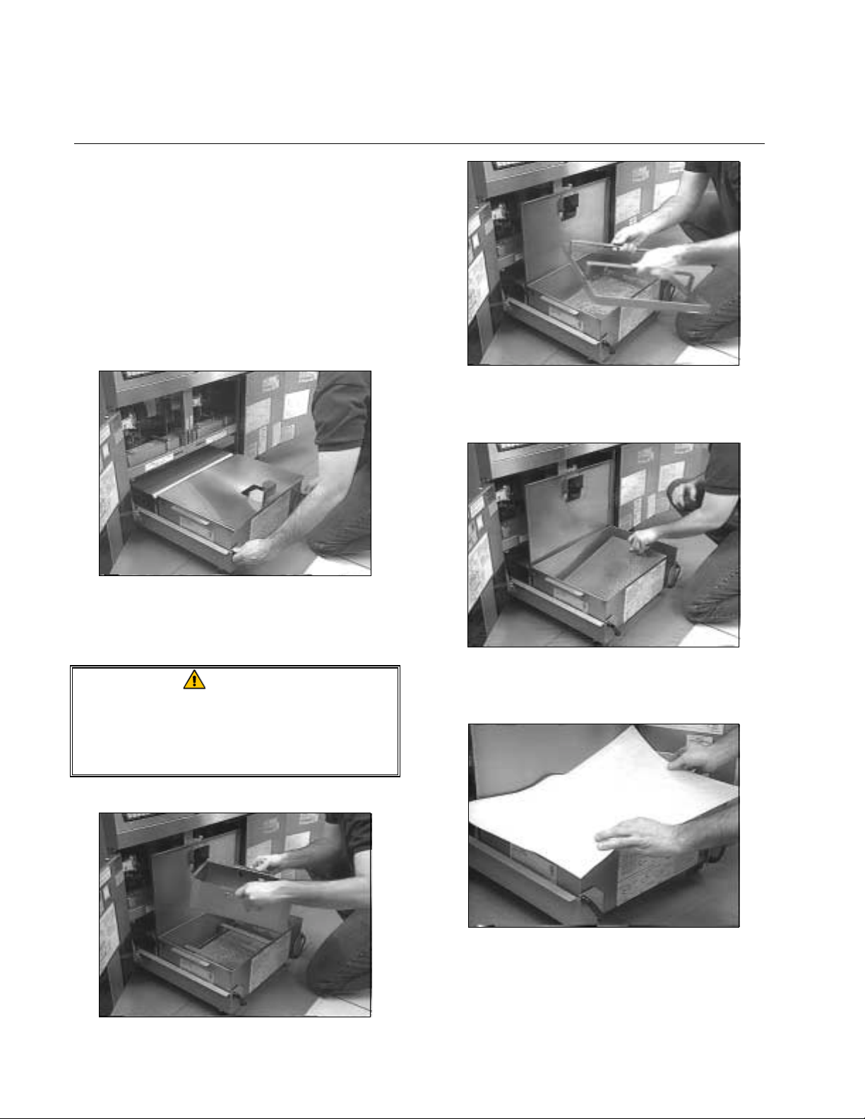
PREPARING THE FILTER UNIT FOR USE
1. Slide the filter unit from the cabinet.
3. Ensure that the metal filter screen is in the
bottom of the pan.
2. Open the cover and remove the crumb tray
and the paper hold-down ring.
CAUTION
Make sure the inside of the pan is free
of all food and breading particles that
could prevent the paper from sealing
against the bottom of the pan.
4. Lay a sheet of filter paper over the top of
the filter pan, overlapping on all sides.
5. Position the hold-down ring over the filter
paper and lower the ring into the pan, allowing the paper to fold up around the ring
as it is pushed to the bottom of the pan.
4-2
Page 31

47 SERIES GAS FRYERS
CHAPTER 4: FILTRATION INSTRUCTIONS
6. Sprinkle filter powder over the filter paper.
For powder quantity, see the filter powder
manufacturer’s instructions.
7. Replace the crumb tray in the filter pan and
close the cover.
OPERATION OF THE FILTER UNIT
CAUTION
Never operate the filter unit unless the
cooking oil in the fryers has been
brought up to cooking temperature.
1. To filter the cooking oil, turn the fryer
power OFF, then open the drain valve on
the fryer you have selected to be filtered.
If necessary, use the Fryer's Friend steel
rod to clear the drain from inside the frypot as necessary.
Valve
shown in
closed
position.
8. Roll the filter pan back into the fryer, positioning it all the way to the back of the
cabinet.
DANGER
Never drain more than one fryer at a
time—the filter pan may overflow.
When unclogging a valve, DO NOT
insert anything into the drain from the
front of the fryer. Hot oil/shortening
will rush out, creating an extreme
hazard.
WARNING
DO NOT hammer on the drain valve
with the Fryer’s Friend. This will
damage the drain valve ball and
prevent the valve from sealing
securely, resulting in a leaky valve.
2. When the frypot is empty, use a fryer
scouring tool to remove sediment on the
4-3
Page 32

47 SERIES GAS FRYERS
CHAPTER 4: FILTRATION INSTRUCTIONS
sides of the frypot. When cleaning the inside of the frypot, avoid striking the high
limit thermostat and temperature probe or
operating thermostat.
3. Snap the Power Shower into the frypot.
DANGER
DO NOT operate the filter without the
Power Shower in place. Hot oil will
spray out of the fryer and may
cause injury.
4. After all oil has drained from the pot, ro-
tate the filter handle to the
RETURN posi-
tion to start the pump and begin the filtering process. There may be a slight delay
before the pump activates.
5. After the oil is completely filtered, close
the drain valve and allow the fryer to refill.
Allow the filter to run 10 to 12 seconds
after bubbles appear in the oil to clear the
lines and prevent hardening of shortening
in the lines.
WARNING
The filter pump is equipped with a
manual reset switch in case the filter
motor overheats or an electrical fault
occurs. If this switch trips, turn off
power to the filter system and allow
the pump motor to cool 20 minutes
before attempting to reset the switch.
6. When the fryer is full, move the filter han-
dle to the OFF position. Remove the
Power Shower and allow it to drain.
4-4
Page 33

47 SERIES GAS FRYERS
CHAPTER 4: FILTRATION INSTRUCTIONS
7. Make sure the drain valve is fully closed.
Turn the fryer ON and allow the cooking
oil/shortening to reach setpoint.
NOTE: Ensure the fryer drain valve is fully
closed before turning the fryer on. If the drain
valve is not fully closed, the controller will
display an error message or a trouble light and
fryer will not operate.
CHANGING THE FILTER PAPER
DANGER
Allow the filter pan to cool completely
before attempting to change the paper.
1. Slide the filter unit from the cabinet.
3. Remove the hold-down ring from the filter
pan and clean.
4. Remove and discard the used filter paper.
2. Remove and clean the crumb tray.
5. Remove the metal filter screen and clean
thoroughly using a solution of hot water
and detergent. Allow the screen to dry
completely before reinstalling.
4-5
Page 34

47 SERIES GAS FRYERS
CHAPTER 4: FILTRATION INSTRUCTIONS
6. Clean all breading and food particles from
the filter pan.
CAUTION
Make sure the inside of the pan is free
of all food and breading particles that
could prevent the paper from sealing
against the bottom of the pan.
7. Replace the metal filter screen in the bot-
tom of the pan.
9. Position the hold-down ring over the filter
paper on top of the pan and lower the ring
into the pan, allowing the filter paper to
fold up around the ring as it is pushed to
the bottom of the pan.
10. Sprinkle filter powder over the filter paper.
For powder quantity and instructions, see
the powder manufacturer's instructions.
11. Replace the crumb tray in the filter pan
and close the cover.
8. Lay a sheet of filter paper over the top of
the filter pan with the paper overlapping
the pan on all sides.
12. Roll the filter pan back into the fryer cabi-
net, making sure that the pan is positioned
all the way to the back of the cabinet.
4-6
Page 35

47 SERIES GAS FRYERS
CHAPTER 5: PREVENTIVE MAINTENANCE
5.1 Fryer Preventive Maintenance
Checks and Services
DAILY CHECKS AND SERVICES
Inspect Fryer and Accessories for Damage
Look for loose or frayed wires and cords,
leaks, foreign material in frypot or inside
cabinet, and any other indications that the
fryer and accessories are not ready and safe for
operation.
Clean Fryer Cabinet Inside and Out
Clean inside the fryer cabinet with dry, clean
cloth. Wipe all accessible metal surfaces and
components to remove accumulations of oil or
shortening and dust.
Clean the outside of the fryer cabinet with a
clean, damp cloth soaked with dishwashing
detergent, removing oil/shortening, dust, and
lint from the fryer cabinet.
measure of the fryer’s efficiency, and it should
be no more than 2 minutes and 30 seconds. If
the recovery time is greater than 2:30, call
your Factory Authorized Service Center
(FASC) or the
The recovery time on models having CM III
computers is automatically measured by the
computer. For fryers with any other type controller, the recovery time must be manually
measured.
To view the recovery time on fryers equipped
with CM III computers, press the Program
Mode Switch . CODE will appear in the
left display. Enter the code number 1652 us-
ing the number keys. The latest recovery time
will appear in both displays for 5 seconds.
To check the recovery time on fryers equipped
with other t han CM III com pute rs, a stop watch
(or a watch with a second hand) and a good
grade thermometer or pyrometer is required.
Frymaster
Frymaster
FrymasterFrymaster
Service Hotline.
DANGER
Never attempt to clean fryer during the
cooking process or when the frypot is
filled with hot oil/shortening. If water
comes in contact with oil/shortening
heated to cooking temperature, it can
cause the oil/shortening to splatter and
severely burn nearby personnel.
WEEKLY CHECKS AND SERVICES
Check Recovery Time
“Recovery time” is the amount of time it takes
the fryer to increase the frypot temperature
from 275°F (135°C) to 325°F (163°C). It is
a
Turn the fryer on and set the controller to
cooking temperature. Place the thermometer
or pyrometer in the frypot. When the frypot
reaches 275°F (135°C), start the stopwatch or
record the time. When the temperature
reaches 325°F (163°C), stop the stopwatch or
record the time.
QUARTERLY CHECKS AND SERVICES
Drain and Clean Frypot
During normal usage of your fryer, a deposit
of carbonized cooking oil or shortening will
gradually form on the inside of the frypot.
This deposit must be periodically removed to
maintain your fryer’s efficiency.
5-1
Page 36

47 SERIES GAS FRYERS
CHAPTER 5: PREVENTIVE MAINTENANCE
DANGER
Allow oil/shortening to cool to 100ºF
(38ºC) or lower before draining to an
appropriate container for disposal.
If your fryer is not equipped with a built-in
filtration system, the cooking oil or shortening
must be drained into another suitable container.
AND DISPOSAL OF USED COOKING OIL OR
SHORTENING
USING OUR
(SDU). THE SDU IS AVAILABLE THROUGH
YOUR LOCAL DISTRIBUTOR.
FOR SAFE, CONVENIENT DRAINING
, FRYMASTER RECOMMENDS
SHORTENING DISPOSAL UNIT
1. Place the fryer power switch in the OFF
position. Screw the drainpipe (provided
with your fryer) into the drain valve.
Make sure the drainpipe is firmly screwed
into the drain valve and that the opening is
pointing down.
2. Position a metal container with a sealable
cover under the drainpipe. The metal
container must be able to withstand the
heat of the cooking oil/shortening and hold
hot liquids. If you intend to reuse the oil
or shortening, Frymaster recommends
that our filter cone holder and filter cone
be used when a filter machine is not available. If you are using a
Frymaster
®
filter
cone holder, be sure that the cone holder
rests securely on the metal container.
3. Open the drain valve slowly to avoid
splattering. If the valve becomes clogged
with food particles, use the Fryer’s Friend
(poker-like tool) to clear the blockage.
DANGER
DO NOT insert the tool into the drain
from the front to unclog the valve. Hot
oil/shortening will rush out, creating an
extreme hazard.
WARNING
DO NOT hammer on the drain valve.
This will damage the drain valve ball
and prevent the valve from sealing
securely, resulting in a leaky valve.
4. After draining the oil/shortening, clean all
food particles and residual oil/shortening
from the frypot. BE CAREFUL, this
material may still cause severe burns if it
comes in contact with bare skin.
5. Close the drain valve securely and fill the
frypot with a solution of detergent and
water to the bottom OIL-LEVEL line.
(Frymaster recommends the use of
Frymaster® Boilout Solution, available
through your local distributor, for best
results.)
6. For units with thermostats, set the thermostat to its lowest setting and bring the
frypot contents to a boil. Simmer the solution for 1 hour. If the solution boils
over, press the ON/OFF switch to the OFF
position immediately.
For units with computers, program the
computer for Boil Operation as outlined in
the Section 3.2, Computer Magic III Operation and Programming. Simmer 1 hour.
7. After the solution has simmered for 1
hour, press the ON/OFF switch to the OFF
position and allow the solution to cool.
8. Drain the solution into a suitable container
(NOT the FootPrint III filter pan or the
Shortening Disposal Unit) and wipe the
frypot thoroughly with a clean towel.
9. Close the drain valve and fill the frypot
with clean, cold water and drain. Repeat
5-2
Page 37

47 SERIES GAS FRYERS
CHAPTER 5: PREVENTIVE MAINTENANCE
the rinse process again, and then wipe frypot with a clean, dry towel.
DANGER
Ensure that the frypot is completely
free of water before filling with cooking
oil or shortening. When the oil or
shortening is heated to cooking
temperature, water in the frypot will
cause splattering.
Clean Detachable Parts and Accessories
As with the frypot, a deposit of carbonized
oil/shortening will accumulate on detachable
parts and accessories such as baskets, sediment trays, or fish plates
Wipe all detachable parts and accessories with
a clean cloth dampened with a detergent solution. (Frymaster recommends the use of
Frymaster® Fryer ‘N’ Griddle Cleaner, avail-
able through your local distributor, for best
results.) Rinse and thoroughly dry each part.
Check Calibration of Thermostat or Analog
Controller Temperature Control Knob
4. When the burner starts for the fourth time,
the thermometer/pyrometer reading should
be within ± 5ºF (2ºC) of the thermostat
knob setting. If it is not, calibrate as follows:
a. Loosen setscrew in thermostat control
knob until the knob will rotate freely
on its shaft.
b. Rotate the knob until the index line on
the knob is aligned with the marking
that corresponds to the thermometer or
pyrometer reading.
c. Hold the knob and carefully tighten the
setscrew.
d. Recheck the thermometer/pyrometer
reading against the thermostat knob
setting the next time the burner lights.
e. Repeat steps 4.a. through 4.d. until the
thermometer/pyrometer reading and
knob setting agree within ± 5ºF (2ºC).
5. Remove the thermometer or pyrometer.
(This check applies only to units equipped
with Thermostat or Analog Controllers)
1. Set the thermostat knob to frying tem-
perature.
2. Let the burner cycle on and off automati-
cally three times to allow the cooking
oil/shortening temperature to become uniform. If necessary, stir to get all shortening in the bottom of the frypot melted.
3. Insert a good-grade thermometer or py-
rometer probe into the oil/shortening, with
the end touching the fryer temperature
probe.
If calibration cannot be obtained, call a Factory Authorized Service Center for assistance.
Check Thermostat Controller Thermostat
Calibration
(This check applies only to units equipped
with Thermostat Controllers.)
1. Set the temperature control knob to 325°F
(162°C) and insert a good grade thermometer or pyrometer into the frypot so
that it touches the temperature probe
guard.
5-3
Page 38

47 SERIES GAS FRYERS
CHAPTER 5: PREVENTIVE MAINTENANCE
2. When the burner cycles off, set the temperature control knob to 340°F (170°C).
As the reading on the thermometer or
pyrometer nears the control knob setting,
but before the burner cycles off, reset the
knob to 325°F (162°C). Just as the
reading on the thermometer or pyrometer
drops below 325°F (162°C), the burner
should cycle on. If it does not, calibration
is required. Call your Factory Authorized
Service Center (FASC) to arrange this
service.
Check Computer Magic III Set Point
Accuracy
(This check applies only to units equipped
with Computer Magic III Controllers.)
Insert a good-grade thermometer or pyrometer
probe into the oil/shortening, with the end
touching the fryer temperature-sensing probe.
Clean Gas Valve Vent Tube
1. Set the fryer power switch and the gas
valve to the OFF position.
2. Carefully unscrew the vent tube from the
gas valve. NOTE: The vent tube may be
straightened for ease in removal.
3. Pass a piece of ordinary binding wire (.052
inch diameter) through the tube to remove
any obstruction.
4. Remove the wire and blow through the
tube to ensure it is clear.
5. Reinstall tube and bend so that the opening
is pointing downward.
SEMI-ANNUAL CHECKS AND
SERVICES
Check Burner Manifold Pressure
1. When the com puter display shows a series
of four dashes “----” with no dot between
the first and second dashes (indicating that
the frypot contents are within the cooking
range), press the
switch once to display
the temperature of the cooking oil or
shortening as sensed by the temperature
probe.
2. Press the switch twice to display the set
point.
3. Note the temperature on the thermometer
or pyrometer. All three readings should be
within ± 5ºF (2ºC) of each other. If not,
contact a Factory Authorized Service
Center for assistance.
WARNING
This task should be performed by
qualified service personnel only.
1. Ensure that the gas valve knob is in the
OFF position.
2. Remove the pressure tap plug from the gas
valve (see arrows in photos below for
location).
Non-CE Electronic
Ignition Valve
Non-CE Pilot
Ignition Valve
CE Pilot
Ignition Valve
5-4
Page 39

47 SERIES GAS FRYERS
CHAPTER 5: PREVENTIVE MAINTENANCE
3. Insert the fitting for a gas pressuremeasuring device into the pressure tap
hole.
4. Place the gas valve in the ON position then
place the fryer power switch in the ON
position. When the burner lights and
continues to burn, note gas pressure
reading for correct pressure in accordance
with the accompanying tables.
Non-CE Standard
Burner Manifold Gas
Pressures
Gas Pressure
Natural
LP
CE Standard
Burner Manifold Gas Pressures
Gas
Natural Gas Lacq
(G20) under 20 mbar
Natural Gas Gronique *
(G25) under 25 mbar
Propane
(G31) under 37 or 50 mbar
* Belgian G25 = 7,0 mbar
3.5" W.C.
0.8 kPa
8.25" W.C.
2.5 kPa
Pressure
(mbar)
8
10
21
5.2 FootPrint III Filtration System Preventive Maintenance Checks and Services
DANGER
Always allow cooking oil/shortening to
cool below 100ºF (38ºC) before trans-
porting to the disposal area.
Frymaster recommends the use of a
Shortening Disposal Unit, available
from your local distributor, for your
safety.
WARNING
Never operate the filter system without
cooking oil/shortening in the system.
WARNING
Never use the filter pan to transport old
cooking oil/shortening to the disposal
area.
WARNING
Never drain water into the filter pan.
Water will damage the filter pump.
There are no periodic preventive maintenance
checks and services required for your
Foo t P r int III F iltration System other than daily
cleaning of the filter pan with a solution of hot
water and detergent.
5. To adjust burner gas pressure, remove the
cap from the gas valve regulator and adjust
to correct pressure.
6. Place the fryer power switch and the gas
valve in the OFF position. Remove the
fitting from the pressure tap hole and
reinstall the pressure tap plug.
If you notice that the system is pumping
slowly or not at all, verify that the filter pan
screen is on the bottom of the filter pan, with
the paper on top of the screen. If the filter
screen and paper are correctly installed,
change the filter paper and verify that the
o-ring on the bottom of the filter pan is present
and in good condition.
5-5
Page 40

47 SERIES GAS FRYERS
CHAPTER 5: PREVENTIVE MAINTENANCE
Immediately after each use, drain the Power
Shower completely. If you suspect blockage,
unscrew the clean-out plugs at each corner of
the frame. Place the frame in a pan of hot
water for several minutes to melt any
accumulation of solidified oil/shortening. Use
a long, narrow bottlebrush with hot water and
detergent to clean inside the tubes. If
necessary, insert a straightened paper clip or
similar instrument into the holes in the frame
to remove any blockages. Rinse, dry
thoroughly, and reinstall the plugs before
using.
DANGER
Failure to reinstall the clean-out plugs
will cause hot oil/shortening to spray
out of the frypot during the filtering
process, creating an extreme burn
hazard to personnel.
5-6
Page 41

47 SERIES GAS FRYERS
CHAPTER 6: OPERATOR TROUBLESHOOTING
6.1 Introduction
This chapter provides an easy reference guide
to the more common problems that may occur
during the operation of your equipment. The
troubleshooting guides in this chapter are
intended to help you correct, or at least
accurately diagnose, problems with your
equipment. Although the chapter covers the
most common problems reported, you may
very well encounter a problem not covered. In
such instances, the Frymaster Technical
Service Department will make every effort to
help you identify and resolve the problem.
When troubleshooting a problem, always use a
process of elimination starting with the
simplest solution and working through to the
most complex. Never overlook the obvious.
Anyone can forget to plug a cord into a
receptacle or put a piece of filter paper into a
filter pan. Don’t assume that you are exempt
from such occurrences.
Most importantly, always try to establish a
clear idea of why a problem has occurred.
Part of your corrective action involves taking
steps to ensure that it doesn’t happen again. If
a controller malfunctions because of a poor
connection, check all other connections while
you’re at it. If a fuse continues to blow, find
out why. Always keep in mind that failure of
a small component may often be indicative of
potential failure or incorrect functioning of a
more important component or system.
Several of the corrective actions recommended
in this chapter involve removing suspect
components from the system and substituting
components that are known to be working.
Whenever this is indicated, refer t o Chapter 7,
Service Procedures, for detailed instructions.
Each guide begins with a description of a
common problem in a six-sided figure.
Simply follow the arrows and answer the
questions to determine the corrective action to
take.
If you are in doubt as to the proper action to
take, do not hesitate to call the Frymaster
Technical Service Department or your local
Frymaster Factory Authorized Service Center
for assistance.
DANGER
Hot cooking oil or shortening causes
severe burns. Never attempt to move a
fryer containing hot cooking
oil/shortening or to transfer hot
cooking oil/shortening from one
container to another.
DANGER
Use extreme care when performing
electrical circuit tests. Live circuits
will be exposed.
WARNING
Inspection, testing, and repair of
electrical equipment should be
performed only by qualified service
personnel. The equipment should be
unplugged when servicing, except
when electrical tests are required.
6-1
Page 42

47 SERIES GAS FRYERS
CHAPTER 6: OPERATOR TROUBLESHOOTING
6.2 Troubleshooting Fryers Equipped with Controllers Other Than CM III
BURNER DOES
NOT LIGHT. POWER,
HEAT, AND TROUBLE
LIGHTS ARE ON.
Verify that main gas supply
valve is open and that the
fryer gas valve is in the ON
position. Verify that the
drain valve is fully closed.
How is fryer configured?
Electronic Ignition
Press Power Switch OFF,
then back ON.
Yes
Did burner light?
No
Press Power Switch OFF,
remove and reconnect gas
line at quick-disconnect.
Press Power Switch ON.
Pilot Ignition
Yes
Yes
Is pilot lit?
Attempt to light pilot.
Did pilot
light and remain
lit?
Remove and reconnect
gas line at
quick-disconnect.
Attempt to light pilot.
No
No
Problem resolved.
Call Service Technician.
Yes
Did burner light?
No
Problem is beyond scope
of Operator
Troubleshooting.
Press Power Switch OFF,
then back ON.
6-2
Yes
Did pilot
light and remain
lit?
No
Page 43

47 SERIES GAS FRYERS
CHAPTER 6: OPERATOR TROUBLESHOOTING
Troubleshooting Fryers Equipped with Controllers Other Than CM III
POWER SWITCH IS
ON. NO LIGHTS ON
CONTROLLER ARE ON.
FRYER DOES NOT
HEAT.
Verify that fryer is plugged
in. Press Power Switch
OFF, then back ON.
Does fryer
operate properly?
No
Press Power Switch OFF,
disconnect unit from electrical
power, remove controller and
replace with another known to
be working.
Reconnect unit to
electrical power. Press
Power Switch ON.
Do other
Yes No
fryers (if present)
operate correctly?
Yes
Problem resolved.
Does fryer
operate properly?
No
Verify that circuit breaker
to fryers is ON. Press
Power Switch ON.
Yes
Does fryer
operate properly?
No
Problem is beyond scope
of Operator
Troubleshooting.
Yes
Probable cause is
defective controller.
6-3
Call Service Technician.
Page 44

47 SERIES GAS FRYERS
CHAPTER 6: OPERATOR TROUBLESHOOTING
Troubleshooting Fryers Equipped with Controllers Other Than CM III
BURNER LIGHTS.
POWER AND TROUBLE
LIGHTS ARE ON, BUT HEAT
LIGHT IS OFF. FRYER
DOES NOT HEAT.
Press Power Switch OFF,
disconnect unit from electrical
power, remove controller and
replace with another known to
be working.
Probable cause is
defective controller.
Reconnect unit to
electrical power. Press
Power Switch ON.
Yes No
Call Service Technician.
Does fryer
operate properly?
Problem is beyond scope
of Operator
Troubleshooting.
6-4
Page 45

47 SERIES GAS FRYERS
CHAPTER 6: OPERATOR TROUBLESHOOTING
Troubleshooting Fryers Equipped with Controllers Other Than CM III
POWER SWITCH IS
ON. POWER LIGHT IS ON.
HEAT LIGHT IS ON, BUT
BURNER DOES NOT
FIRE.
Is 24V LED
on interface board
No
lit?
Yes
Press Power Switch OFF
and disconnect unit from
electrical power. Replace
fuse in ignition module.
Reconnect unit to
electrical power. Press
Power Switch ON.
Yes No
Does fryer
operate properly?
Problem resolved.
Call Service Technician.
6-5
Problem is beyond scope
of Operator
Troubleshooting.
Page 46

47 SERIES GAS FRYERS
CHAPTER 6: OPERATOR TROUBLESHOOTING
Troubleshooting Fryers Equipped with Controllers Other Than CM III
POWER IS ON.
DISPLAY SHOWS "HELP"
AND ALARM IS SOUNDING,
BUT FRYER OPERATES
NORMALLY.
Press Power Switch OFF,
disconnect unit from electrical
power, remove controller and
replace with another known to
be working.
Reconnect unit to
electrical power. Press
Power Switch ON.
Probable cause is
defective controller.
Yes No
Does fryer
operate properly?
Probable cause is
defective controller wire
harness.
Call Service Technician.
Press Power Switch OFF,
disconnect unit from
electrical power, replace
controller wire harness with
another known to be good.
Reconnect unit to
electrical power. Press
Power Switch ON.
Yes
Does fryer
operate properly?
No
Problem is beyond scope
of Operator
Troubleshooting.
6-6
Page 47

47 SERIES GAS FRYERS
CHAPTER 6: OPERATOR TROUBLESHOOTING
Troubleshooting Fryers Equipped with Controllers Other Than CM III
POWER SWITCH OFF, BUT
HEAT LIGHT REMAINS ON.
FRYER CONTINUES TO HEAT
UNTIL TROUBLE LIGHT COMES ON.
OIL TEMP ABOVE 410 DEGREES
F (210 DEGREES C).
Press Power Switch OFF,
disconnect unit from electrical
power, remove controller and
replace with another known to
be working.
Probable cause is
defective controller.
Reconnect unit to
electrical power. Press
Power Switch ON.
Yes No
Call Service Technician.
Does fryer
operate properly?
Problem is beyond scope
of Operator
Troubleshooting.
6-7
Page 48

47 SERIES GAS FRYERS
CHAPTER 6: OPERATOR TROUBLESHOOTING
Troubleshooting Fryers Equipped with Controllers Other Than CM III
FRYER OPERATING
NORMALLY, BUT
FLAMES ARE ROLLING
OUT THE FRONT OF
THE BURNER.
Press Power Switch OFF,
disconnect unit from electrical
power, place gas valve in
OFF position. Remove and
clean gas valve vent tube.
Reinstall gas valve vent tube.
Reconnect unit to electrical
power. If unit is not equipped
with electronic ignition, relight
pilot. Press Power Switch ON.
Problem resolved.
Yes No
Does fryer
operate properly?
Problem is beyond
scope of Operator
Troubleshooting.
Call Service Technician.
6-8
Page 49

47 SERIES GAS FRYERS
CHAPTER 6: OPERATOR TROUBLESHOOTING
6.3 Troubleshooting Fryers Equipped with Computer Magic III Computers
DISPLAY SHOWS
"HELP" WITH ALARM
SOUNDING.
Do other
fryers (if present)
operate normally?
Yes
Verify drain valve is fully
closed and fryer gas valve is
in the ON position. Press
Power Switch OFF then
back ON.
Did burner light?
No
Yes
No
Verify that main gas
supply valve is open.
Press Power Switch
OFF, then back ON.
No
Did burner light?
Problem resolved.
Yes
Press Power Switch OFF, turn
main gas supply valve off, remove
and reconnect gas line Quick
Disconnect. Turn main gas supply
valve on, press Power Switch ON.
Call Service Technician.
Yes
Did burner light?
No
Problem is beyond scope
of Operator
Troubleshooting.
6-9
Page 50

47 SERIES GAS FRYERS
CHAPTER 6: OPERATOR TROUBLESHOOTING
Troubleshooting Fryers Equipped with Computer Magic III Computers
NO DISPLAY ON
COMPUTER OR DISPLAY
SHOWS "PROB" WITH
ALARM SOUNDING.
Verify that fryer is plugged
in. Press Power Switch
OFF, then back ON.
Does fryer
operate properly?
No
Press Power Switch OFF,
disconnect unit from electrical
power, remove controller and
replace with another known to
be working.
Reconnect unit to
electrical power. Press
Power Switch ON.
Do other
Yes No
fryers (if present)
operate correctly?
Yes
Problem resolved.
Does fryer
operate properly?
No
Verify that circuit breaker
to fryers is ON. Press
Power Switch OFF, the
back ON.
Yes
Does fryer
operate properly?
No
Problem is beyond scope
of Operator
Troubleshooting.
Yes
Probable cause is
defective controller.
6-10
Call Service Technician.
Page 51

47 SERIES GAS FRYERS
CHAPTER 6: OPERATOR TROUBLESHOOTING
Troubleshooting Fryers Equipped with Computer Magic III Computers
POWER IS ON.
DISPLAY SHOWS "HELP"
AND ALARM IS SOUNDING,
BUT FRYER OPERATES
NORMALLY.
Press Power Switch OFF,
disconnect unit from electrical
power, remove controller and
replace with another known to
be working.
Reconnect unit to
electrical power. Press
Power Switch ON.
Probable cause is
defective controller.
Yes No
Does fryer
operate properly?
Probable cause is
defective controller wire
harness.
Call Service Technician.
Press Power Switch OFF,
disconnect unit from
electrical power, replace
controller wire harness with
another known to be good.
Reconnect unit to
electrical power. Press
Power Switch ON.
Yes
Does fryer
operate properly?
No
Problem is beyond scope
of Operator
Troubleshooting.
6-11
Page 52

47 SERIES GAS FRYERS
CHAPTER 6: OPERATOR TROUBLESHOOTING
Troubleshooting Fryers Equipped with Computer Magic III Computers
DISPLAY SHOWS
"CYCL" OR "LO", BUT
BURNER DOES NOT
FIRE.
Verify that drain valve is
fully closed. Press Power
Press Power Switch OFF and
disconnect unit from electrical
power. Replace fuse in ignition
module. Reconnect unit to
electrical power. Press Power
Switch ON.
Switch OFF, then back
No Yes
ON.
Does burner light?
Does fryer
operate properly?
No
Yes
Press Power Switch OFF,
disconnect unit from electrical
power, remove and replace
computer with another known to be
working. Reconnect to electrical
power. Press Power Switch ON.
Reconnect unit to
electrical power. Press
Power Switch ON.
Does fryer
operate properly?
No
Yes
Does fryer
operate properly?
No
Press Power Switch OFF,
disconnect unit from
electrical power, replace
computer wire harness with
another known to be good.
Probable cause is
defective computer wire
harness.
Problem resolved.
Yes
Probable cause is
defective computer.
Call Service Technician.
Problem is beyond scope
of Operator
Troubleshooting.
6-12
Page 53

47 SERIES GAS FRYERS
CHAPTER 6: OPERATOR TROUBLESHOOTING
Troubleshooting Fryers Equipped with Computer Magic III Computers
COMPUTER WILL
NOT GO INTO
PROGRAMMING
MODE.
Press Power Switch OFF, disconnect
unit from electrical power, unplug
computer wiring harness from interface
board. Wait 2 minutes. Reconnect
computer wiring harness, reconnect unit
to electrical power, press Power Switch
ON.
Does
computer operate
properly?
No
Press Power Switch OFF,
disconnect unit from electrical
power, remove computer and
replace with another known to
be working.
Reconnect unit to
electrical power. Press
Power Switch ON.
Does
computer operate
properly?
Yes
YesNo
Problem resolved.
Problem is beyond scope
of Operator
Troubleshooting.
Probable cause is
defective computer.
Call Service Technician.
6-13
Page 54

47 SERIES GAS FRYERS
CHAPTER 6: OPERATOR TROUBLESHOOTING
Troubleshooting Fryers Equipped with Computer Magic III Computers
FRYER OPERATING
NORMALLY, BUT
FLAMES ARE ROLLING
OUT THE FRONT OF
THE BURNER.
Press Power Switch OFF,
disconnect unit from electrical
power, place gas valve in
OFF position. Remove and
clean gas valve vent tube.
Reinstall gas valve vent tube.
Reconnect unit to electrical
power. If unit is not equipped
with electronic ignition, relight
pilot. Press Power Switch ON.
Problem resolved.
Yes No
Does fryer
operate properly?
Problem is beyond
scope of Operator
Troubleshooting.
Call Service Technician.
6-14
Page 55

47 SERIES GAS FRYERS
CHAPTER 6: OPERATOR TROUBLESHOOTING
6.4 Troubleshooting the FootPrint III Filtration System
PUMP DOES NOT
START.
Verify that filter power
cord is plugged in and that
circuit breaker is on.
Move filter handle to OFF
position, then back to ON
position.
Did pump start? Problem resolved.
No
Yes
Move filter handle to OFF position.
Is Thermal
Overload Switch on
pump motor
tripped?
No
Allow oil/shortening to cool, then empty
Yes
pan and verify that filter paper and
screen have been properly installed and
are clean. Reset Thermal Overload
Switch and move the filter handle to the
ON position.
Probable causes are a
defective 24-volt
transformer, a defective
Did pump start?
YesNo
Did Thermal
Overload Switch trip
pump controller microswitch,
or a defective motor.
Probable cause is a pump blockage.
Pump blockages are usually caused
Call Service Technician.
by sediment build-up in the pump due
to improperly sized or installed filter
No
off again?
Yes
paper.
6-15
Page 56

47 SERIES GAS FRYERS
CHAPTER 6: OPERATOR TROUBLESHOOTING
Troubleshooting the FootPrint III Filtration System
PUMP STARTS,
BUT NO TRANSFER
TAKES PLACE.
Move filter handle to OFF position.
Allow oil/shortening to cool, then
empty pan. Verify that o-ring on
pan outlet is present and in good
condition. Verify that filter paper
and screen have been properly
installed and are clean. Refill the
filter pan and move filter handle to
the ON position.
Problem resolved.
Yes No
Is oil/shortening being
returned to frypot?
Yes
Is oil/shortening being
returned to frypot?
No
Probable causes are solidified
oil/shortening in filtration unit return
lines or blockage of return line
suction tube on bottom of filter pan.
A blockage of the return line
suction tube is usually due to
sediment/food particle build-up
caused by failure to use crumb tray
and the use of improperly sized or
installed filter paper. Failure of
solidified oil/shortening in the return
lines to melt indicates a defective
heater tape or 24 volt transformer.
Probable cause is solidified
oil/shortening in the filtration
unit return lines. Move filter
handle to the OFF position,
wait 10 minutes, the move
filter handle to ON position.
Call Service Technician.
6-16
Page 57

47 SERIES GAS FRYERS
CHAPTER 6: OPERATOR TROUBLESHOOTING
Troubleshooting the FootPrint III Filtration System
POWER SHOWER
NOT SPRAYING
PROPERLY.
Move filter handle to the OFF
position. Remove Power Shower
from frypot and verify that o-rings
and seal on inlet are present and in
good condition. Verify that clean-out
screws at each corner of the Power
Shower frame are present and tight.
Verify that the receptacle in the
frypot is not obstructed. Reinstall
Power Shower, ensuring that inlet
seats properly in its receptacle.
Move the filter handle to the ON
postion.
Problem resolved.
Call Service Technician.
Yes No
Is the Power
Shower spraying
properly?
Yes
Is the Power
Shower spraying
properly?
No
Problem is beyond
scope of Operator
Troubleshooting.
Probable cause is
solidified oil/shortening
in the Power Shower
tubing.
Move the filter handle to the OFF
position and remove the unit from the
frypot. Remove the clean-out
screws and place the unit in a pan of
hot water for several minutes to melt
the oil/shortening. Insert a
straightened paper clip or similar
instrument into each hole to clear
any blockages. Replace and tighten
clean-out screws. Reinstall Power
Shower, ensuring that it seats
properly in its receptacle. Move the
filter handle to the ON position.
6-17
Page 58

Troubleshooting the FootPrint III Filtration System
Problem resolved.
47 SERIES GAS FRYERS
CHAPTER 6: OPERATOR TROUBLESHOOTING
AFTER FILTERING, FRYER
DOES NOT OPERATE PROPERLY.
TROUBLE LIGHT ON (UNITS WITH
OTHER THAN CM III COMPUTERS)
OR CM III COMPUTER DISPLAY
SHOWS "HELP".
Verify that drain valve is
fully closed.
Refer to Troubleshooting
Yes No
Is fryer operating
properly?
Guides in Sections 6.2 (for
units without CM III computers)
or 6.3 (for units with CM
III computers).
6-18
Page 59

CHAPTER 6: OPERATOR TROUBLESHOOTING
Troubleshooting the FootPrint III Filtration System
Carefully tighten each set
of clamps.
47 SERIES GAS FRYERS
DRAIN TUBE
LEAKING.
Allow all oil/shortening to drain
from tube. Inspect tube sections
for holes or cracks. Inspect rubber
gaskets at each joint for holes or
cracks.
Are tube
Yes No
sections and gaskets
free of holes or
cracks?
Operate filtration system.
Is drain tube still
leaking?
No
Problem resolved.
Yes
Call Service Technician.
6-19
Page 60

47 SERIES GAS FRYERS
CHAPTER 7: SERVICE PROCEDURES
7.1 Functional Description
The 47 Series fryers contain a welded stainless
steel frypot that is directly heated by gas
flames that are diffused evenly over its lower
surface by ceramic “targets.”
In full vat configurations, the flames originate
from orifices in a U-shaped burner manifold
positioned beneath the frypot. In dual (split)
vat configurations, the U-shaped manifold is
replaced by a pair of J-shaped manifolds, one
for each vat. The diameter of the orifices differs for natural and LP gas as indicated in the
accompanying table.
47 Series Orifice Sizes
Gas Drill Size Millimeters
Natural 53 1.45
LP 65 0.86
activated by the fryer ON/OFF switch, provides voltage through the thermostat or controller to the gas valve main coil, which opens
the main valve. The gas valve is constructed
so that the main valve will not open if the pilot
valve is not open. The pilot flame must be
manually lit when the fryer is first placed into
operation.
ON/OFF
Controlling Thermostat
or
Controller
Thermopile
Pilot
Switch
Main Coil
Gas Valve
Pilot Coil
The Pilot System
Transformer
24 VAC
Line Voltage
Line Voltage
High-Limit
Thermostat
Gas flow to the manifold(s) is regulated by an
electromechanical gas valve. This series of
fryers is equipped with a 24-volt valve system.
Units with thermostat controls will have a pilot ignition (millivolt) system, and those with
other type controllers may be configured with
either a pilot ignition (millivolt) system or an
electronic ignition system.
PILOT SYSTEM CONFIGURATION
The pilot system is comprised of the pilot orifice, pilot hood, and a thermopile. The pilot
serves two purposes. The first is to light the
burner, the second is to heat the thermopile.
In operation, the thermopile is in contact with
the pilot flame and generates millivolts. The
millivolt output passes through a normally
closed high-limit switch and energizes the gas
valve pilot coil, which in turn opens the pilot
valve. If the pilot flame is extinguished, voltage is lost to the gas valve pilot coil and the
pilot valve closes. A separate 24-volt circuit,
ELECTRONIC IGNITION CONFIGURATION
In units configured for electronic ignition, an
ignition module connected to an igniter assembly replaces the pilot system. The ignition
module performs four important functions: it
provides fuse protection for the 24-volt circuit,
provides an ignition spark, supplies voltage to
the gas valve, and proofs the pilot flame.
Inside the Ignition Module
Out to
Gas Valve
To Alarm
25 V +
Coil
TD
HV
25 V GND
Ignition Wire Flame Sensor
7-1
Page 61

47 SERIES GAS FRYERS
CHAPTER 7: SERVICE PROCEDURES
The module contains a 4-second time delay
circuit and a coil that activates the gas valve.
The igniter assembly consists of a spark plug,
a pilot, and a flame sensor element.
At start-up the ON/OFF switch is placed in the
ON position, supplying 12-volts DC to the
heat control circuitry in the controller or computer and to one side of the heat relay coil on
the interface board. If resistance in the temperature probe indicates the temperature in the
frypot is below 180ºF (82ºC), the current
flows through a melt cycle circuit where a
timer switch alternately closes for 3 seconds
and opens for 24 seconds. If the temperature is
180ºF (82ºC) or above, the current flows
through a heat circuit, bypassing the timer
switch. In either case, current is supplied to
the other leg of the heat relay coil which then
closes an electronic switch in the 24 VAC circuit to provide current to the ignition module.
Circuitry in the ignition module sends 24
VAC current to the gas valve via a normally
closed high-limit switch and a drain safety
switch. Simultaneously, the module causes
the igniter to spark for 4 seconds to light the
pilot flame. A flame sensor verifies that the
pilot is lit by measuring the flow of microamps through the flame. If the pilot does not
light (or is extinguished), current to the ignition module is cut, preventing the main valve
from opening, and the ignition module “locks
out” until the power switch is turned off then
back on.
CONTROL OPTIONS
47 Series fryers may be equipped with thermostat controls, solid-state analog controls,
solid-state digital controls, basket lift timers,
or Computer Magic III computers.
In fryers equipped with thermostat controls,
the fryer and melt cycle are turned on and off
by means of rocker switches and the temperature is set by means of a knob connected directly to the frypot-mounted thermostat.
These units have no interface board. In this
type unit, once started, the melt cycle will
continue until it is manually turned off regardless of the temperature in the frypot.
Fryers equipped with other types of controllers
have an interface board located in the component box (shield) behind the control panel.
INTERFACE BOARDS
The interface board provides a link between
the controller/computer and the fryer’s individual components without requiring excessive wiring, and allows the controller to execute commands from one central point. Two
types of interface boards may be used in 47
Series fryers; the type used depends on the
fryer configuration.
In units configured for electronic ignition, P/N
806-5857 is used; the other board is P/N 806-
3398.
A temperature probe monitors the temperature
in the frypot. When the programmed setpoint
temperature is reached, resistance in the probe
causes the heat cycle circuitry in the controller
to cut off current flow through the heat relay.
This in turn cuts off the 24 VAC current to the
ignition module, resulting in closure of the gas
valve.
IFB 806-5857. This board contains two types
of relays. Heat relays (K1 and K3) operate at
12 volts DC output from the controller. They
switch 24 VAC to the main gas circuit when
the unit calls for heat. The middle relay (K2)
switches 24 VAC to the pilot circuit when the
unit is powered up. The purpose of this relay
is to allow the pilot to remain continuously lit.
7-2
Page 62

47 SERIES GAS FRYERS
CHAPTER 7: SERVICE PROCEDURES
J1
SOUND
1
2
3
PWR
4
GND
3
V1
2
AL
1
12 6 3 45
MV
AL
12 9 63
8 5
PV
HEAT
RELAY
2
1
410117
CMP PWR 24V
15
12 9 63
14
1513
K1
8
STANDING
PILOT
RELAY
K2
J2
MV
PV
2
5
410117
J3
1
AL
K3
HEAT
RELAY
12 9 63
8 5
J4
2
1
410117
GND
PWR
J5
1
AL
2
V1
3
4
INTERFACE BOARD P/N 806 -5857
FREQUENTLY USED TEST POINTS FOR INTERFACE BOARD P/N 8 06-5857
Meter
Test Setting Pins Results
12V AC Pow e r to Controller 50V AC Scale 1 and 3 on J3 12-18
24V AC Pow e r to Right Module 50V AC Scale 4 on J5 and GROUND 22-28
24V AC Pow e r to Le ft Module 50VAC Scale 4 on J1 and GROUND 22-28
12V AC Pow e r to Right MBL Relay 50VAC Scale 7 on J3 and 9 on J4 12-18
12V AC Pow e r to Le ft MBL Relay 50VA C Sc ale 9 on J3 and 6 on J2 12-18
24V AC Pow e r to Right High-Limit 50VAC Sc ale 12 on J4 and GROUND 22-28
24V AC Pow e r to Le ft High-Limit 50VAC Sc ale 3 on J2 and GROUND 22-28
Probe Resistance ( Right)
*
Probe Resistance (Left) * R x 1000 OHMS 14 on J3 and 1 on J2 **
High-Limit Continuity (Right) R x 1 OHM 12 on J4 and Wire 13C on Gas Valve 0
High-Limit Continuity (Left) R x 1 OHM 3 on J2 and Wire 12C on Gas Valve 0
** Disconnect 15-pin har ness from controller before testing probe circuit.
** See Probe Resistance Chart at end of chapter.
R x 1000 OHMS 14 on J3 and 10 on J4 **
7-3
Page 63

47 SERIES GAS FRYERS
CHAPTER 7: SERVICE PROCEDURES
INTERFACE BOARD
12VAC TO CPTR
GROUND
12 VAC RETURN
COMPUTER
COMPUTER
COMPUTER
COMPUTER
NOT USED NOT USED
COMPUTER
CPTR-RT ALARM
COMPUTER
CPTR-LT ALARM
COMPUTER
COMPUTER
COMPUTER
1
2
3
RT HT RELAY (K3)
4
12VDC TO RELAYS
5
LT HT RELAY (K1)
6
7
8
9
10
11
12
13
J4 PIN 11 & J2 PIN 2
14
15
J2
J3
TEMP PROBE
TEMP PROBE
J2 PIN 4 via HLS, DSS,
and PILOT VALVE
PILOT VALVE
MAIN GAS VALVE
BASKET LIFT
NOT USED
NOT USED
NOT USED
NOT USED
GROUND
NOT USED
1
2
3
4
5
6
7
8
9
10
11
12
J4 PIN 1
GROUND
J4 PIN 3
J4 PIN 9
J2 PIN 6
J5 PIN 1
SOUND DEVICE
J1 PIN 1
J4 PIN 10
J2 PIN 1
J3 PIN 15
J3 PIN 14
J1 PIN 2
K1
K1
J3 PIN 9
NOT USED
NOT USED
NOT USED
NOT USED
GROUND
NOT USED
J4
J3 PIN 1
GROUND
J3 PIN 3
J5 PIN 4 via K 2
NOT USED NOT USED
NOT USED NOT USED
K3
K3
J3 PIN 7
J3 PIN 13
J3 PIN 14
J5 PIN 2
12VAC XFMR PIN 11
1
2
12VAC XFMR PIN 12
3
4
5
6
7
MAIN GAS VALVE
8
9
TEMP PROBE
10
TEMP PROBE
11
J4 PIN 7 via HLS, DSS,
12
and PILOT VALVE
GROUND
24V XFMR PIN 8
PILOT VALVE
BASKET LIFT
MOD ALARM
MOD VALVE TERM
MOD 25V GROUND
MOD 25V TERM
J1
1
2
3
4
J3 PIN 12
J2 PIN 3
GROUND
J4 PIN 4 via K2
J3 PIN 10
J4 PIN 12
GROUND
J4 PIN 4 via K2
J5
1
2
3
4
MOD ALARM
MOD VALVE TERM
MOD 25V GROUND
MOD 25V TERM
LEFT VAT FULL OR RIGHT VAT
CURRENT FLOW THROUGH
INTERFACE BOARD 806-5857
7-4
Page 64

47 SERIES GAS FRYERS
CHAPTER 7: SERVICE PROCEDURES
GND
J1
GND
V2D
PWR
AD
AS
V2S
SOUND
1
2
3
3 6 9 12
2 5 8 11
1 4 7 10
13
10741
11852
J2
14
15
12963
3 6 9 12
2 5 8 11
J3
1 4 7 10
K3 K4 K5
BASKET
LIFT
RELAY
HEAT
RELAY
NOT
USED
BASKET
LIFT
RELAY
HEAT
RELAY
K1 K2
12 6 3 45
GND
GND
V1D
PWR
ALR
V1S
GND GV PWR
AL 12V AIR 24V AL
PWR
GV
GND
INTERFACE BOARD P/N 806-3398
FREQUENTLY USED TEST POINTS FOR INTERFACE BOARD P/N 8 06-3398
Meter
Test Setting Pins Results
12V AC Pow e r to Controller 50V AC Scale 1 and 3 on J3 12-18
24V AC Pow e r to Right Module 50V AC Scale 8 on J3 and GROUND 22-28
24V AC Pow e r to Le ft Module 50VAC Scale 8 on J1 and GROUND 22-28
12V AC Pow e r to Right MBL Relay 50VAC Scale 7 on J2 and 7 or 10 on J3 12-18
12V AC Pow e r to Le ft MBL Relay 50VA C Sc ale 9 on J2 and 7 or 10 on J1 12-18
24V AC Pow e r to Right High-Limit 50VAC Sc ale 9 on J3 and GROUND 22-28
24V AC Pow e r to Le ft High-Limit 50VAC Sc ale 9 on J1 and GROUND 22-28
Probe Resistance ( Right)
Probe Resistance (Left) * R x 1000 OHMS 2 on J1 and 6 on J1 **
High-Limit Continuity (Right) R x 1 OHM 9 on J3 and Wire 13C on Gas Valve 0
High-Limit Continuity (Left) R x 1 OHM 9 on J1 and Wire 12C on Gas Valve 0
** Disconnect 15-pin har ness from controller before testing probe circuit.
** See Probe Resistance Chart at end of chapter.
*
R x 1000 OHMS 2 on J3 and 6 on J3 **
7-5
Page 65

47 SERIES GAS FRYERS
CHAPTER 7: SERVICE PROCEDURES
INTERFACE BOARD
12 VAC TO CPTR
GROUND
12 VAC RETURN
COMPUTER
COMPUTER
COMPUTER
COMPUTER K5
NOT USED NOT USED
COMPUTER K3
RT ALARM OUT
COMPUTER SOUND DEVICE
LT ALARM OUT
COMPUTER
COMPUTER
COMPUTER
1
2
3
4
5
6
7
8
9
**
10
11
*
12
13
14
15
J1
NOT USED NOT USED
NOT USED
TEMP PROBE
BASKET LIFT (DN)
24 VAC IN
MAIN GAS VALVE
via HLS via HLS
BASKET LIFT (UP)
AC COMMON AC COMMON AC COMMON
NOT USED NOT USED
1
2
3
4
5
6
7
8
9
10
11
12
J3 PIN 1
GROUND
J3 PIN 3
RT HT RELAY (K2)
12 VDC TO RELAYS
LT HT RELAY (K1)
ALR (RIGHT)
AD (LEFT)
J3 PIN 6
J1 PIN 2 & J3 PIN 2
J1 PIN 6
J2 PIN 14TEMP PROBE
NOT USEDNOT USED
NOT USED
NOT USEDNOT USED
J2 PIN 15
K3
PWR via K1
V2D
K3
** Dual Vat configurations
** Full Vat configurations
J2 PIN 1
J2 PIN 14 TEMP PROBE
J2 PIN 3
NOT USED
NOT USED NOT USED
J2 PIN 13
K5 BASKET LIFT (DN)
PWR via K2
V1S OR V1D
K5
NOT USED NOT USED
J3
1
2
3
4
5
6
7
8
9
10
11
12
J2
12 VAC XF M R PIN 11
12 VAC XF M R PIN 12
NOT USED
TEMP PROBE
24 VAC IN
MAIN GAS V A LVE
BASKET LIFT (UP)
AC COMMON
MOD 25V GROUND GR OU ND
MOD V2D
MOD 25V TERM
DRAIN SWITCH (OP T)
NOT USED N OT US E D
NOT USED N OT US E D
GND
V2D
PWR
AD
AS
V2S
J1 PIN 9
J1 PIN 8 via K1
J2 PIN 12
LEFT VAT FULL OR RIGHT VAT
GROUND MOD 25V GROUND
J3 PIN 9
J3 PIN 8 vi a K2
J3 PIN 9
CURRENT FLOW THROUGH
INTERFACE BOARD 806-3398
7-6
GND
V1D
PWR
ALR
V1S
MOD V1D
MOD 25V TERM
DRAIN SWITCH (OPT)J2 PIN 10
MOD V1S
*
**
Page 66

47 SERIES GAS FRYERS
CHAPTER 7: SERVICE PROCEDURES
The following table identifies the meaning associated with each of the LEDs arranged
across the top of the interface board. NOTE:
For full vat units, ignore the left-side LEDs.
P/N 806-5857 INTERFACE BOARD
LED DIAGNOSTIC LIGHTS
AL Indi cates ignition module lockout
MV Indicates 24 VAC t o gas main valve
PV Indicates 24 VA C to pilot valve
CMP Indicates 12 VAC from transformer
24V Indicates 24 V A C from transformer
PWR Indicates 24 V AC to ignition module
IFB 806-3398. This standard interface board
is used in a number of fryer types besides the
47 Series. In the 47 Series, it is used in pilot
ignition (millivolt) systems only. The infor-
mation contained in this section applies
only to 47 Series applications.
The board contains two heat relays (K1 and
K2), and two basket lift relays (K3 and K5).
Relay K4 has no function in 47 Series appli-
cations. NOTE: On factory-original units not
equipped with basket lifts, the board will have
no basket lift relays installed. Like the 806-
5857 interface board, LEDs are provided to
assist in troubleshooting.
Fryers equipped with Thermostat Controls
have an adjustable controlling thermostat.
The temperature at which the thermostat opens
and closes is adjusted by physically changing
the setting of the thermostat itself by means of
an attached knob. The Fenwal controlling
thermostat used in the 47 Series fryers is sensitive to one-degree changes in temperature.
CAUTION
Fenwal thermostats are used in a
number of Frymaster™ products. The
thermostat for the 47 Series is 4 inches
long. Do not use 3-inch Fenwal
thermostats in 47 Series fryers.
Fryers equipped with all other type controls
have a temperature probe. In this type ther-
mostat, the probe resistance varies directly
with the temperature. That is, as the temperature rises, so does resistance at a rate of
approximately 2 ohms for every 1º (F or C).
Circuitry in the controller monitors the probe
resistance and controls burner firing when the
resistance exceeds or falls below programmed
temperatures (setpoints). The temperatures
are programmed by means of a keypad on the
face of the controller.
P/N 806-3398 INTERFA CE BOARD
LED DIAGNOSTIC LIGHTS
Indica tes 12 VAC f rom transfo r mer
12V
Indica tes 24 VAC f rom transfo r mer
24V
Ind ic a tes 24 VAC to gas valve
GV
Ind ic a tes 24 VAC to PWR via K1 (L) or K2 (R or F)
PWR
Indicates open Dr ain Safety Sw itch (if installed)
AL
No function in 47 Ser ies ap plications
AIR
THERMOSTATS
Different types of thermostats are used in 47
Series fryers, depending on the fryers’ configuration.
All 47 Series fryers are equipped with a high-
limit thermostat. In the event that the fryer
fails to properly control the oil temperature,
the high-limit thermostat prevents the fryer
from overheating to the flash point. The highlimit thermostat acts as a normally closed
power switch that opens when exposed to
temperatures above 425ºF to 450ºF (218ºC to
232ºC). The different types of thermostats
have different part numbers for CE and NonCE configured models, and are not interchangeable.
7-7
Page 67

47 SERIES GAS FRYERS
CHAPTER 7: SERVICE PROCEDURES
7.2 Accessing Frye rs for Servicing
DANGER
Moving a fryer filled with cooking
oil/shortening may cause spilling or
splattering of the hot liquid. Follow the
draining instructions in Chapter 4 of
this manual before attempting to
relocate a fryer for servicing.
1. Shut off the gas supply to the unit. Unplug
the power cords. Disconnect the unit from
the gas supply.
2. Remove any attached restraining devices.
3. Relocate the fryer for service accessibility.
4. After servicing is complete, reconnect the
unit to the gas supply, reattach restraining
devices, and plug in the electrical cords.
Proper spacing of the top edge of the burner
ceramic targets is ¾ inch (13 mm) from the
frypot side. To adjust target spacing, bend the
brackets to which they are attached away or
toward the frypot to the proper distance. (A
length of board of the proper thickness is useful as a gauge to verify spacing and alignment.)
7.6 Adjusting the Pilot Flame
1. Remove the cap from the pilot adjustment
screw hole on the gas valve.
2. Using a small, flat-tipped screwdriver, turn
the pilot adjusting screw counterclockwise
to increase length of flame or clockwise to
decrease length of flame. Adjust to obtain
a flame from 1 inch to 1½ inches long.
3. Reinstall the pilot adjustment screw cap.
7.3 Cleaning the Gas Valve Vent Tube
Refer to Semi-Annual Checks and Services in
Chapter 5, Preventive Maintenance.
7.4 Checking the Burner Manifold Gas Pressure
Refer to Semi-Annual Checks and Services in
Chapter 5, Preventive Maintenance.
7.5 Adjusting Burner Ceramic Target Spacing and Alignment
DANGER
Drain the frypot or remove the handle
from the drain valve before proceeding
further.
7.7 Calibrating the Thermostat Control
NOTE: The fryer control panel must be
hinged down from the control panel mounting
frame to perform thermostat calibration. In
order to hinge the control panel down, the
thermostat knob must be removed from its
shaft.
1. Fill the frypot to the lower OIL-LEVEL
line with cooking oil/shortening. If solid
shortening is used, it must be pre-melted
before starting the calibration procedure.
2. Ensure the fryer ON/OFF Switch is in the
OFF position, then light the pilot. (Refer
to Chapter 3 for detailed lighting instructions.)
7-8
Page 68

47 SERIES GAS FRYERS
CHAPTER 7: SERVICE PROCEDURES
3. Insert a good grade thermometer or pyrometer into the frypot so that it touches
the thermostat guard.
4. Disconnect the solid extension shaft from
the end of the flexible shaft using an appropriately sized Allen wrench.
5. Remove the flexible shaft from the thermostat shaft screw.
6. Place the fryer ON/OFF switch in the ON
position.
NOTE: If the burner does not light at this
time, it does not mean the thermostat is defective. Recheck the wiring, and then
slowly turn the thermostat adjusting screw
counterclockwise until the burner lights.
Turning the adjusting screw counterclockwise causes the burner to light and
clockwise causes it to shut off.
cycle on and off at least 3 times to be sure
it will light at the calibrated temperature.
11. After the calibration is complete, place the
fryer power switch in the OFF position and
disconnect the fryer from the electrical
supply.
12. Carefully install the thermostat flexible
extension on the thermostat shaft, ensuring
that the setscrews are tight.
CAUTION
The thermostat adjusting screw must
not be moved while installing the
flexible extension shaft.
13. Install the solid metal extension shaft on
the end of the flexible shaft with the stop
pin at the 12 o’clock position. Ensure the
stop pin and setscrews are tight to prevent
slippage.
7. When the cooking oil/shortening temperature reaches 325ºF (162ºC), turn the
thermostat adjusting screw slowly clock-
wise until the burner shuts off.
8. Allow the fryer to sit for a few minutes,
then slowly turn the thermostat adjusting
screw counterclockwise until the burner
lights.
9. Repeat steps 7 and 8 at least three times to
ensure an accurate setting is obtained. The
Thermostat Control is considered to be
properly calibrated if the burner lights as
the cooking oil/shortening cools to 325ºF
(162ºC)—not when the burner shuts off as
the temperature rises.
10. Once the calibration point of 325ºF
(162ºC) is determined, allow the burner to
14. Reinstall and secure the fryer control
panel. Loosen the temperature dial plate
screws and rotate the dial until the 325ºF
(162ºC) index mark is at the 12 o’clock
position, then retighten the screws.
15. Reinstall the thermostat knob with its
pointer aligned with the 325ºF (162ºC) index mark on the temperature dial plate.
Tighten the thermostat knob set screws to
prevent slippage.
7.8 Replacing Fryer Components
7.8.1 Replacing the Controller or
Computer
1. Disconnect the fryer from the electrical
supply.
7-9
Page 69

47 SERIES GAS FRYERS
CHAPTER 7: SERVICE PROCEDURES
2. Unscrew the two control panel screws.
The control panel is hinged at the bottom
and will swing open from the top.
3. Unplug the fryer wiring harness from the
back of the controller/computer.
4. Remove the controller/computer by lifting
it from the hinge slots in the fryer control
panel frame.
5. Reverse the procedure to install a new
controller/computer.
7.8.2 Replacing the Thermostat
1. Disconnect the fryer from the electrical
supply.
2. Drain cooking oil/shortening below level
of probe.
3. Remove thermostat knob. Remove the
screws from the upper left and right corners of the control panel. The control panel
is hinged at the bottom and will swing
open from the top.
4. Disconnect the wiring plug(s)from the
component shield/control box.
8. Unscrew the thermostat from the frypot
and remove.
9. Apply Loctite™ PST56765 thread sealant
or equivalent to the replacement thermostat threads.
10. Reverse steps 1 through 8 to install the
replacement.
CAUTION
The Thermostat Control must be
calibrated after installation is
complete. Refer to Section 7.7 for
calibration instructions.
7.8.3 Replacing the Temperature
Probe
1. Disconnect the fryer from the electrical
supply.
2. Drain cooking oil/shortening below level
of probe.
3. Remove the screws from the upper left and
right corners of the controller panel. The
controller is hinged at the bottom and will
swing open from the top.
5. Remove the control panel from the fryer
by disengaging its tabs from the hinge
slots in the mounting frame.
6. Remove the solid extension shaft from the
end of the flexible shaft using an appropriately sized Allen wrench. Remove the
flexible shaft from the thermostat shaft
screw.
7. Disconnect leads from terminal block.
4. Unplug the wiring harness from the back
of the controller.
5. Remove the controller from the fryer by
disengaging its tabs from the hinge slots in
the mounting frame.
6. Remove two screws and nuts from the
base of the interface board mounting
bracket.
7-10
Page 70

47 SERIES GAS FRYERS
CHAPTER 7: SERVICE PROCEDURES
7. Disconnect the 12-pin plug from the back
of the interface board and lay the board in
the left end of the compartment with all
other wires still connected.
8. Remove the 12-volt transformer from the
component shield and lay it in the left end
of the compartment with wires still connected.
9. Using a pin-pusher, remove the temperature probe wires from the 12-pin plug disconnected in step 7.
10. Unscrew the temperature probe from the
frypot and remove.
11. Apply Loctite™ PST56765 thread sealant
or equivalent to new probe threads.
12. Reverse steps 1 through 10 to install replacement probe.
5. Remove the control panel from the fryer
by disengaging its tabs from the hinge
slots in the mounting frame.
6. Remove the molded high-limit thermostat
wire adapter from the gas valve pilot coil.
7. Unscrew the high-limit thermostat from
the frypot and remove
8. Apply Loctite™ PST56765 thread sealant
or equivalent to the replacement thermostat threads
9. Reverse steps 1 through 7 to install the
replacement high-limit thermostat.
7.8.5 Replacing the High-Limit
Thermostat in Fryers with
Temperature Probes
1. Disconnect the fryer from the electrical
supply.
7.8.4 Replacing the High-Limit Thermostat in Fryers with Thermostat Controls
1. Disconnect the fryer from the electrical
supply.
2. Drain cooking oil/shortening below the
level of the thermostat.
3. Remove the thermostat knob. Remove the
screws from the upper left and right corners of the control panel. The control panel
is hinged at the bottom and will swing
open from the top.
4. Disconnect the wiring plug(s) from the
component shield/control box.
2. Drain cooking oil/shortening below the
level of the thermostat.
3. Remove the screws from the upper left and
right corners of the controller panel. The
controller is hinged at the bottom and will
swing open from the top.
4. Unplug the wiring harness from the back
of the controller.
5. Remove the controller from the fryer by
disengaging its tabs from the hinge slots in
the mounting frame.
6. Remove two screws and nuts from the
base of the interface board mounting
bracket.
7-11
Page 71

47 SERIES GAS FRYERS
CHAPTER 7: SERVICE PROCEDURES
7. Disconnect the 12-pin plug from the back
of the interface board and lay board in the
left end of compartment with all other
wires still connected.
8. Remove the high-limit thermostat wires
from the gas valve pilot coil and pull them
up through the control shield.
9. Unscrew the high-limit thermostat from
the frypot and remove.
10. Apply Loctite™ PST56765 thread sealant
or equivalent to new thermostat threads.
11. Reverse steps 1 through 9 to install the
replacement thermostat.
7.8.6 Replacing Control Panel Power
Indicator Light in Fryers with
Thermostat Control
1. Disconnect the fryer from the electrical
supply.
2. Remove the thermostat knob.
7. Reverse steps 1-4 to reassemble fryer.
7.8.7 Replacing Power or Melt Cycle Switch in Fryers with Thermostat Controls
1. Disconnect the fryer from the electrical
supply.
2. Remove the thermostat knob.
3. Remove the screws from the upper left and
right corners of the control panel. The
control panel is hinged at the bottom and
will swing open from the top.
4. Unplug the control panel wiring harness
from the component shield/control box.
5. Unsnap the chrome bezel from the rear of
the switch and push the switch out through
the rear of the control panel.
6. Remove wires one at a time from the
switch and connect to the replacement
switch until all wires are transferred.
3. Remove the screws from the upper left and
right corners of the control panel. The
control panel is hinged at the bottom and
will swing open from the top.
4. Unplug the control panel wiring harness
from the component shield/control box.
5. Carefully press the light out of the back
side of the control panel. Remove one
wire terminal at a time and connect to the
replacement light until all wires are transferred.
6. Carefully press the light back into the
control panel.
7. Reverse steps 1-5 to reassemble fryer.
7.8.8 Replacing Melt Cycle Timer Motor in Fryers with Thermostat Controls
1. Disconnect the fryer from the electrical
supply.
2. Remove the thermostat knob.
3. Remove the screws from the upper left and
right corners of the control panel. The
control panel is hinged at the bottom and
will swing open from the top.
7-12
Page 72

47 SERIES GAS FRYERS
CHAPTER 7: SERVICE PROCEDURES
4. Remove the screws securing the timer
motor to the fryer.
5. Remove one wire at a time and connect to
the replacement timer motor until all wires
have been transferred.
6. Reverse steps 1-4 to reassemble fryer.
7.8.9 Replacing Burner Ceramic
Targets
DANGER
Drain the frypot or remove the handle
from the drain valve before proceeding
further.
1. Disconnect fryer from electrical and gas
supplies.
2. Disconnect the wires from the gas valve
terminal block, marking each wire to facilitate reconnections.
9. To replace only the ceramic targets,
straighten the target locking tabs with a
pair of needle nose pliers or a screwdriver,
and slide the target up and off the bracket.
Slide the replacement target onto the
bracket and bend the locking tabs down.
To replace the entire target assembly, using a ½-inch box end wrench, remove the
two brass orifices that hold the assembly
to the burner manifold, replace the assembly, and replace the orifices.
WARNING
Use extreme care to prevent cross-
threading and stripping when
reinstalling the brass orifices.
10. Reverse steps 1-8 to reinstall the burner
assembly. Check spacing and alignment
of targets in accordance with Section 7.5.
7.8.10 Replacing the Gas Valve
3. Remove the high-limit thermostat wires
from the gas valve pilot coil.
4. Remove the pipe union collar at the left
side of the gas valve.
5. Remove the burner heat shield hanger
screws at the front of the burner and remove the heat shield.
6. Remove the burner hanger screws.
7. Lower the front of the main burner and
pull it forward to clear the rear burner
hanger. Lower the burner to the floor.
8. Raise the fryer enough to slide the burner
from under the fryer cabinet.
DANGER
Drain the frypot or remove the handle
from the drain valve before proceeding
further.
1. Disconnect fryer from electrical and gas
supplies
2. Disconnect the wires from the gas valve
terminal block, marking each wire to facilitate reconnections.
3. Remove the high-limit thermostat wire
from the gas valve pilot coil.
4. Remove the pilot gas line fitting from the
gas valve.
7-13
Page 73

47 SERIES GAS FRYERS
CHAPTER 7: SERVICE PROCEDURES
5. Remove the pipe union collars to the left
and right of the gas valve and remove the
valve.
6. Remove the pipefittings from the old gas
valve and install on the replacement valve,
using Loctite™ PST56765 or equivalent
pipe thread sealant on threads.
7. Reverse steps 1-5 to install the replacement gas valve.
7.8.11 Replacing the Pilot Assembly
DANGER
Drain the frypot or remove the handle
from the drain valve before proceeding
further.
1. Remove the burner assembly in accordance with Section 7.7.9.
2. Remove the pilot tubing from the bottom
of the pilot assembly.
3. Bend the clip at the bottom of the pilot assembly and remove the pilot. Disconnect
the pilot fitting from the gas valve pilot
coil.
2. Lift the molded plastic wire adapter assembly and wires out of the pilot coil.
3. Cut the in-line splices from the wire
adapter and high-limit thermostat wires.
4. Strip the wire insulation from the end of
the high-limit thermostat wires and splice
on a new high-limit thermostat wire
adapter assembly.
5. Insert the new molded plastic wire adapter
into the gas valve pilot coil.
6. Screw the pilot electrical fitting into the
gas valve pilot coil finger tight, then 1/8
turn more with a wrench.
7.8.13 Replacing the Frypot
1. Drain cooking oil/shortening from the frypot.
2. Remove all accessories, e.g., frypot covers,
basket lift arms, etc. from the fryer.
3. Disconnect the fryer from gas and electrical supplies.
4. Remove the two pilot mounting screws
from the pilot mounting bracket and remove the pilot.
5. Reverse the procedure to replace the pilot
assembly.
7.8.12 Replacing Gas Valve High-Limit
Thermostat Wire Adapter
1. Remove the pilot electrical fitting from the
gas valve pilot coil.
4. Remove the screws from the top cap above
the control panel and lift it up and off the
fryer(s).
5. If the fryer is equipped with other than a
Thermostat Control, skip to Step 10.
6. Remove the thermostat knob. Remove the
screws from the upper left and right corners of the control panel. Disconnect the
control panel from the fryer wiring harness
and remove it from the fryer.
7-14
Page 74

47 SERIES GAS FRYERS
CHAPTER 7: SERVICE PROCEDURES
7. Remove the thermostat flexible shaft from
the thermostat shaft adjusting screw.
8. Remove the two screws and nuts from the
thermostat shaft bracket and lift the thermostat flexible shaft and bracket out of the
component box.
9. Disconnect both wires from the gas valve
and the 20-hole terminal block. Skip to
Step 14.
10. For fryers equipped with other than Thermostat Controls, remove the screws from
the upper left and right corners of the control panel. Disconnect the controller from
the fryer wiring harness and remove it
from the fryer.
11. Remove the two screws and nuts from the
base of the interface board bracket.
thermostat wire adapter from the slot. Pull
the high-limit thermostat wires and adapter
up through the grommet at the rear of the
box.
18. Remove the wires from the gas valve terminal block. Mark each wire to facilitate
reconnection.
19. For fryers equipped with Thermostat Controls, remove the thermostat wire from the
gas valve and pull it up through the grommet at the rear of the box. Disconnect the
other thermostat wire from the 20-hole
terminal block. Mark each wire to facilitate reconnection.
20. Remove the cover from the safety drain
switch, disconnect the wires from the
switch, and pull them out of the switch
box.
12. Disconnect the 12-pin plug from the back
of the interface board and remove the temperature probe and high-limit thermostat
wires from the plug using a pin pusher.
13. Lay the interface board and bracket on top
of the control shield with wires still connected.
14. Remove the louvered frame above the
control panel opening.
15. Remove screws and nuts securing the
component box to the fryer.
16. Disconnect wires from components in
component box and mark to facilitate reconnection.
17. Remove pilot generator fitting from gas
valve pilot coil and lift the high-limit
21. Pull up and forward on the component box
to clear the rear mounting stud on the front
of the frypot.
22. Remove the component box from the fryer
by rotating its right side up and to the left.
23. Remove the pipe union from the right side
of the gas valve.
24. Remove the section of square drain from
the drain valve of the frypot to be removed.
25. Remove the frypot hold down bracket.
26. Remove the screws from the flue cap sides
and back and lift it clear of the fryer(s).
27. Remove the oil return hose or line from
the front of the frypot to be removed.
7-15
Page 75

47 SERIES GAS FRYERS
CHAPTER 7: SERVICE PROCEDURES
28. Lift the frypot complete with burner, gas
valve, flue, and drain valve from the fryer
cabinet.
29. Transfer burner heat shield and burner to
replacement frypot.
30. Remove drain valve, thermostat or temperature probe, and high-limit thermostat
and install on replacement frypot.
6. Leakage problems
7. Modular Basket Lift malfunctions.
The probable causes of each category are discussed in the following sections. A series of
Troubleshooting Guides (decision trees) is
also included at the end of the chapter to assist
in identifying some of the more common
problems.
7.9.1 Ignition Failures
31. Reverse steps 1-28 to reassemble fryer.
CAUTION
Before installing
thermostat/temperature probe,
high-limit thermostat, and drain valve
on replacement frypot, clean their
threads and apply Loctite™ PST56765
thread sealant or equivalent to the
threads.
7.9 Troubleshooting and Problem
Isolation
Because it is not feasible to attempt to include
in this manual every conceivable problem or
trouble condition that might be encountered,
this section is intended to provide technicians
with a general knowledge of the broad problem categories associated with this equipment,
and the probable causes of each. With this
knowledge, the technician should be able to
isolate and correct any problem encountered.
Ignition failure occurs when the ignition module fails to sense a flame within the 4-second
time delay period and locks out. When this
happens, the module sends 24 VAC through
the interface board alarm circuit to the controller/computer.
Solid-state controllers indicate ignition failure
by illuminating the heat light and trouble light
simultaneously. Computer Magic III controls
display “H E L P.”
There are three primary reasons for ignition
failure, listed in order of probability:
1. Problems related to the gas and/or electri-
cal power supplies
2. Problems related to the electronic circuits
3. Problems related to the gas valve.
PROBLEMS RELATED TO THE GAS AND/OR
ELECTRICAL POWER SUPPLIES
Problems you are likely to encounter can be
grouped into seven broad categories:
1. Ignition failures
2. Improper burner functioning
3. Improper temperature control
4. Computer-related problems
5. Filtration problems
The main indicators of this are that an entire
battery of fryers fails to light and/or there are
no indicator lights illuminated on the fryer experiencing ignition failure. Verify that the
quick disconnect hose is properly connected,
the fryer is plugged in, the main gas supply
valve is open, and the circuit breaker for the
fryer electrical supply is not tripped.
7-16
Page 76

47 SERIES GAS FRYERS
CHAPTER 7: SERVICE PROCEDURES
PROBLEMS RELATED TO THE ELECTRONIC
CIRCUITS
If gas and electrical power are being supplied
to the fryer, the next most likely cause of ignition failure is a problem in the 24 VAC circuit
of fryers equipped with electronic ignition
systems, or in the pilot system for those without electronic ignition. If the fryer is equipped
with a FootPrint III filtration system, first verify that the drain valve is fully closed. (The
valve is attached to a microswitch that must be
closed for power to reach the gas valve. Often, although the valve handle appears to be in
the closed position, the microswitch is still
open.) If the valve is fully closed, or the fryer
does not have a filtration system, refer to the
troubleshooting guides TROUBLESHOOTING
THE 24 VAC CIRCUIT
PROBLEMS RELATED TO THE GAS VALVE
.
If the problem is not in the 24 VAC circuit or
pilot system, it is most likely in the gas valve
itself, but before replacing the gas valve refer
to TROUBLESHOOTING THE GAS VALVE on
pages 7–34 through 7–35.
7.9.2 Improper Burner Functioning
The primary causes of popping are:
• Incorrect or fluctuating gas pressure
• Misdirected or weak pilot flame
• Burner deflector targets out of alignment
or missing
• Clogged burner orifices
• Inadequate make-up air
• Heat damage to the controller or ignition
module
• A cracked igniter or broken ignition wire
• A defective ignition module
If popping occurs only during peak operating
hours, the problem may be incorrect or fluctuating gas pressure. Verify that the incoming
gas pressure (pressure to the gas valve) is in
accordance with the appropriate CE or NonCE Standard found in Section 2.3 of this manual, and that the pressure remains constant
throughout all hours of usage. Refer to Check
Burner Manifold Pressure in the semi-
annual checks and services section of Chapter
5 for the procedure for checking the pressure
of gas supplied to the burner.
With problems in this category, the burner ignites but exhibits abnormal characteristics
such as “popping,” incomplete lighting of
burner, fluctuating flame intensity, and flames
“rolling” out of the fryer.
“Popping” indicates delayed ignition. In this
condition, the main gas valve is opening but
the burner is not immediately lighting. When
ignition does take place, the excess gas
“explodes” into flame, rather than smoothly
igniting.
If popping is consistent during all hours of operation, verify that the pilot is properly positioned above the burner orifice and that the
pilot pressure is correct. Correct pilot pressure
is indicated by a flame 1 to 1½” long. Refer to
Section 7.6 for adjustment procedure.
Clogged burner orifices, especially those near
the pilot, are also likely causes of delayed ignition. Clogged orifices are indicated by no
flame, flames that are orange-colored, and
flames that shoot out at an angle from the rest.
7-17
Page 77

47 SERIES GAS FRYERS
CHAPTER 7: SERVICE PROCEDURES
Another cause of popping is an insufficient air
supply or drafts that are blowing the pilot
flame away from the burner. Check for “negative pressure” conditions in the kitchen area.
If air is flowing into the kitchen area, this indicates that more air is being exhausted than is
being replenished and the burners may be
starved for air.
If the fryer’s gas and air supplies are okay, the
problem most likely is with one of the electrical components. Examine the ignition module
for signs of melting/distortion and/or discoloration due to excessive heat build-up in the
fryer. (This condition usually indicates improper flue performance.). Also, examine the
controller for the same conditions. A melted
or distorted ignition module is automatically
suspect and should be replaced, but unless the
condition causing excessive heat in the fryer is
corrected, the problem is likely to recur.
Next, check to ensure the ignition wire is
tightly connected at both ends and examine it
for obvious signs of damage. Again, if damage is due to excessive heat in the fryer, that
problem must also be corrected.
Check for proper operation by disconnecting
the wire from the igniter (spark plug), inserting the tip of a screw driver into the terminal,
and holding it near the frame of the fryer as
the power switch is placed in the ON position.
A strong, blue spark should be generated for at
least 4 seconds.
Examine the igniter (spark plug) for any signs
of cracking. A cracked igniter must be replaced.
The burner lighting on one side only may be
caused by a missing or misaligned rear deflector target or improper burner manifold
pressure. Clogged burner orifices are usually
the cause of gaps in burner firing.
Fluctuating flame intensity is normally
caused by either improper or fluctuating incoming gas pressure, but may also be the result of variations in the kitchen atmosphere.
Verify incoming gas pressure in the same way
as for “popping,” discussed in the preceding
paragraphs. Variations in the kitchen atmosphere are usually caused by air conditioning
and/or ventilation units starting and stopping
during the day. As they start and stop, the
pressure in the kitchen may change from positive or neutral to negative, or vice versa. They
may also cause changes in airflow patterns
that may affect flame intensity.
Flames “rolling” out of the fryer are usually
an indication of negative pressure in the
kitchen. Air is being sucked out of the fryer
enclosure and the flames are literally following the air. If negative pressure is not the
cause, check for high burner manifold gas
pressure in accordance with the procedures in
Chapter 5. An obstructed flue, which prevents
the fryer from properly exhausting, may also
be the cause.
DANGER
MAKE SURE YOU ARE HOLDING THE
INSULATED HANDLE OF THE
SCREWDRIVER AND NOT THE BLADE.
THE SPARKING CHARGE IS
APPROXIMATELY 25,000 VOLTS.
An excessively noisy burner, especially with
flames visible above the flue opening, may
indicate that the burner gas pressure is too
high, or it may simply be that the gas valve
vent tube is blocked. If the gas pressure is
correct and the vent tube in unobstructed, the
gas valve regulator is probably defective.
7-18
Page 78

47 SERIES GAS FRYERS
CHAPTER 7: SERVICE PROCEDURES
Occasionally a burner may apparently be operating correctly, but nevertheless the fryer has a
slow recovery rate (the length of time required
for the fryer to increase the oil temperature
from 275ºF to 325ºF (135ºC to 163ºC)). The
primary causes of this are low burner manifold
pressure and/or misaligned or missing deflector targets. If both of these causes are ruled
out, the probable cause is a misadjusted gas
valve regulator. Refer to the Check Burner
Manifold Pressure procedure in the semi-
annual checks and services section of Chapter
5.
7.9.3 Improper Temperature Control
Temperature control, including the melt cycle,
is a function of several interrelated components, each of which must operate correctly.
The principle component is the thermostat (in
thermostat control units) or the temperature
probe (in fryers equipped with other types of
controllers). Depending upon the specific
configuration of the fryer, other components
may include the interface board, the controller
itself, and the ignition module.
ler itself, the temperature probe, or a malfunctioning heat relay on the interface board.
For problem isolation techniques, refer to the
troubleshooting guides
THE THERMOSTAT
THE TEMPERATURE PROBE
FAILURE TO CONTROL AT SETPOINT
TROUBLESHOOTING
and TROUBLESHOOTING
.
In fryers equipped with thermostat controls,
the problem will be with the thermostat itself.
Possible causes are that the thermostat is out
of calibration, the knob or flexible shaft is
loose on the thermostat adjusting screw, a
thermostat wire is disconnected, or the thermostat is defective. Refer to Section 7.7 for
instructions on calibrating the thermostat.
In fryers equipped with other types of controls,
the problem may be with the temperature
probe, the interface board, or the controller.
Refer to the troubleshooting guide
TROUBLESHOOTING THE TEMPERATURE
PROBE
for problem isolation techniques.
7.9.4 Computer-Related Problems
Improper temperature control problems can be
categorized into melt cycle problems and failure to control at setpoint problems.
MELT CYCLE PROBLEMS
In fryers equipped with thermostat controls,
the melt cycle is controlled by a mechanical
timer. There are three components that may
fail: the melt cycle timer itself, the melt cycle
timer microswitch, or the control panel melt
cycle ON/OFF switch. In all cases, the defective component must be replaced.
In fryers equipped with other types of controllers, the problem may be with the control-
COMPUTER MAGIC III FEATURES
SENSITIVITY OR “STRETCH AND SHRINK TIME”
Sensitivity or stretch time is a programmable
feature, patented by Frymaster that increases
or decreases the cook time countdown based
on variations in the oil temperature from the
set point.
The sensitivity for each product button has ten
settings (0 through 9). A zero sensitivity setting will disable the feature (no change in
cooking time), while a nine will provide the
highest sensitivity or most change. The correct sensitivity for any product is based on the
7-19
Page 79

47 SERIES GAS FRYERS
CHAPTER 7: SERVICE PROCEDURES
product, its density, the set point temperature,
and the customer’s own requirements.
RECOVERY TIME OR “RAT E OF RISE”
Recovery time or rate of rise is a method of
measuring a fryer’s performance. Put simply,
it is the time required for the fryer to increase
the oil temperature from 275ºF to 325ºF
(135ºC to 163ºC). This range is used as a
standard since ambient kitchen temperatures
can effect the test if lower ranges are used.
The Computer Magic III performs the recovery test each day as the fryer warms up. An
operator can view the results of the test any
time the fryer is above the 325ºF (163ºC) point
by pressing the button and entering the
code 1652. The test results will be displayed
in the computer’s LED panel in minutes and
seconds. The acceptable recovery time for the
47 Series of fryers is two minutes.
S1 should be open for non-controlling applications and closed for controlling.
S2 should be open for electric fryers and
closed for gas fryers.
S3 should be open for full vat and closed for
dual vat configurations.
WARNING
Do not attempt to alter the strapping of
the computer. Doing so may render
the computer inoperable and will void
the component warranty.
COMMON COMPUTER COMPLAINTS
Most problems concerning computers have to
do with programming them. There are four
common complaints. The complaints, their
causes, and corrective actions are:
COMPUTER MAGIC III STRAPPING
The Computer Magic III controller does not
automatically recognize a full vat or dual vat
fryer. Each computer is set up at the factory
for full or dual vat, gas or electric, and controlling or non-controlling applications. This
is accomplished through the strapping or unstrapping of the computer’s three dip-type
switches.
Occasionally you may encounter a situation in
which a computer that has been strapped for
one type of fryer has been installed in another
type. An examination of the computer strapping may explain the incorrect functioning of
an otherwise good computer.
The computer’s dip-type switches are numbered S1 through S3, from left to right.
1. Fryer constantly displays “HI.”
Cause: Setpoint incorrect or missing.
Corrective Action: Press 1650, enter
the correct setpoint using keypad, then
press to lock in the setpoint.
2. Temperature is displayed in Celsius.
Cause: Computer is programmed to display in Celsius.
Corrective Action: Press 1658.
3. Temperature is constantly displayed.
Cause: Computer is programmed for constant temperature display.
Corrective Action: Press 165L.
7-20
Page 80

47 SERIES GAS FRYERS
CHAPTER 7: SERVICE PROCEDURES
4. Computer times down too slowly or too
quickly.
Cause: Computer is compensating for oil
temperature via the sensitivity setting.
Corrective Action: Reprogram sensitivity
setting for each product in accordance with
programming instructions in Chapter 3.
7.9.5 Filtration Problems
The majority of filtration problems arise from
operator error. One of the most common
errors is placing the filter paper on the bottom
of the filter pan rather than over the filter
screen.
Whenever the complaint is “the pump is running, but no oil is being filtered,” check the
installation of the filter paper, including that
the correct size is being used. While you are
checking the filter paper, verify that the O-ring
on the bottom of the filter pan is present and
in good condition. A missing or worn O-ring
will allow the pump to suck air and decrease
its efficiency.
More often, the pump overheated for one of
the following reasons:
• Shortening was solidified in the pan or
filter lines.
• The operator attempted to filter oil or
shortening that was not heated. Cold oil
and shortening are thicker and cause the
pump motor to work harder and overheat.
If the motor runs but the pump does not, there
is a blockage in the pump. Incorrectly sized or
installed paper will allow food particles and
sediment to pass through the filter pan and
into the pump. When sediment enters the
pump, the gears can bind up causing the motor
to overload, again tripping the thermal overload. Solidified shortening in the pump will
also cause it to seize, with the same result.
FREEING A SEIZED PUMP
Sediment Particle
Up for reverse
If the pump motor does not start, the most
likely cause is that the filter carriage is not
properly positioned all the way to the rear of
the fryer.
If the pump motor overheats, its thermal
overload will trip and the motor will not start
until it is reset. If the pump motor does not
start, press the red reset switch located on the
rear of the motor. If the pump then starts,
something caused the motor to overheat. It
may be just that several frypots were being
filtered one after the other and the pump got
hot. Letting the pump cool down for at least a
half-hour is all that is required in this case.
Down for forward
A pump seized by debris or hard shortening
can usually be freed by manually moving the
gears with a screwdriver or other instrument.
1. Disconnect power to the filter system.
2. Remove the input plumbing from the
pump.
3. Use a screwdriver to manually turn the
gears.
7-21
Page 81

47 SERIES GAS FRYERS
CHAPTER 7: SERVICE PROCEDURES
• Turning the pump gears backwards
will release a hard particle and allow
its removal.
• Turning the pump gears forward will
push softer objects and solid shortening through the pump and allow
free movement of the gears.
Incorrectly sized or installed paper will also
allow food particles and sediment to pass
through and clog the suction tube on the bottom of the filter carriage. Particles large
enough to block the suction tube may indicate
that the crumb tray is not being used.
Pan blockage can also occur if shortening is
left in the pan and allowed to solidify. The
heater strip on the suction tube is designed to
prevent solidification of residual shortening
left in the tube. It will not melt or prevent solidification of shortening in the pan.
Blockage removal can be accomplished by
forcing the item out with an auger or drain
snake. Compressed air or other pressurized
gases should not be used to force out the
blockage.
Line Voltage
Heater Tapes
24 VAC
Micro-switches
Pump Relay Coil
Pump Motor
M
Pump Motor Switch
FootPrint III Simplified Wiring Diagram
The suction tube heater and flexible hose
heater are wired directly into the 120 VAC
source. They remain energized as long as the
unit is plugged in.
7.9.6 Leakage Problems
Possible problems with the Power Shower include clogged openings, shortening solidified
in the tubes, missing clean-out plugs, and
missing or worn O-rings. Cleaning the unit
and replacing missing plugs and missing or
worn O-rings will correct these problems.
The electronics of the FootPrint III Filter are
simple and straightforward. Microswitches,
attached to handles for each vat and wired in
parallel, provide the 24 VAC required to activate the pump relay coil when the handles are
moved to the ON position. The activated
pump relay coil pulls in the pump motor
switch, supplying power to the pump motor.
Leakage of the frypot almost always will be
due to improperly sealed high limit switches,
thermostats/temperature probes, and drain fittings. When installed or replaced, each of
these components must be sealed with Loctite™ PST56765 sealant or equivalent to prevent leakage. In very rare cases, a leak may
develop along one of the welded edges of the
frypot. When this occurs, the frypot must be
replaced.
If the sides and/or ends of the frypot are
coated with oil/shortening, the most likely
cause is spillage over the top of the frypot
rather than leakage.
7-22
Page 82

47 SERIES GAS FRYERS
CHAPTER 7: SERVICE PROCEDURES
The clamps, which hold the drain tube sections together, may loosen over time as the
tubes expand and contract with heating and
cooling during use. If the section of drain tube
connected to the drain valve is removed for
whatever reason, make sure that its grommet
is in good condition and properly fitted around
the nipple of the drain when it is reinstalled.
Also, check to insure that the drain tube runs
downward from the drain along its whole
length and has no low points where oil or
shortening may accumulate.
7.9.7 Modular Basket Lift Malfunctions
47 Series fryers may optionally be equipped
with automatic basket lifts to ensure uniform
cooking times. The lifts may be configured
for manual control or for control via a Basket
Lift Timer or Computer Magic III computer.
Basket lifts will always come in pairs, although each operates independently.
A lift consists of a toothed rod to which the
basket lift arm is attached, a reversible-drive
gear motor, and a pair of roller-activated microswitches. The gear motor engages the teeth
in the rod, moving it up or down depending
upon the direction of rotation of the motor.
Microswitches at the upper and lower limits of
movement stop the motor when the basket is
in the full up or full down position. In units
configured for manual (push-button) controls,
a mechanical timer controls voltage to the
system. A rotary knob is turned to set the
cook time, and pressing the button in the middle of the knob activates the motor by applying power through the lower micro-switch.
The motor drives the basket lift down. As the
rod moves downward, it closes the upper microswitch, preparing the motor to run in the
opposite direction when the cooking time has
expired. When the rod contacts the lower microswitch, power to the motor is cut and the
motor stops.
MODULAR BASKET LIFT
7-23
A
A
SECTION A - A
Page 83

47 SERIES GAS FRYERS
CHAPTER 7: SERVICE PROCEDURES
Manual (Push-Button)
Modular Basket Lift Simpl if ied Schematic
2-Pole
HN
Mech
Timer
1 or 5
4 or 6
When the timer button is pushed, the lower circuit is activated,
causing the basket lift to be lowered, closing the normally open
upper microswitch. When the lower normally closed microswitch
is opened by the downward moving basket lift rod, power to the
motor is cut. When the timer times-out, the upper circuit is
activated, causing the basket lift to be raised, reclosingthe lower
microswitch. When the basket lift rod clears the upper
micorswitch, allowing it to reopen, power to the circuit is cut and
the motor stops. Pushing the tim er button again restarts t he
cycle.
N.O.
Upper Limit
Microswitch
N.C.
Lower Limit
Microswitch
M
3
When the timer times-out, power is supplied
to the opposite pole of the motor through the
upper microswitch. The motor drives the rod
upward until it loses contact with the upper
microswitch, cutting power to the motor and
stopping the lift.
Computer/Controller
Modular Basket Lift Simpl if ied Schematic
HN
N.O.
Upper Limit
5
1 or 4
To computer/controller
via interface board
When the product button is pushed on the computer/controller,
current flows through a coil in the basket lift relay, causing the
lower circuit to be activated. This causes the basket lift to be
lowered, closing the normally open upper microswitch. When the
lower normally closed microswitch is opened by the downward
moving basket lif t rod, power to th e motor is cut. When the
computer/controller times-out, the current to the relay coil is cut,
allowing the upper circuit to be activated. This causes the basket
lift to be raised, reclosing the lower microswitch. When the
basket lift rod clears the upper micorswitch, allowing it to reopen,
power to the circuit is cut and t he m otor stops. Pushing the
product button again restarts the cycle.
Basket Lift
3
Relay
Microswitch
N.C.
Lower Limit
Microswitch
M
6
Problems with the basket lift system can be
grouped into three categories:
• Binding/jamming problems
• Motor and gear problems
• Electronics problems
In units configured for Basket Lift Timer
Controllers or Computer Magic III computers,
the process is almost identical. The difference
is that the push button mechanical timer is replaced with timing circuitry in the computer or
controller. The specific cook times (and other
settings) are programmed into the computer or
controller by the operator. When the product
button is pressed, the timing circuitry activates
a coil in the basket lift relay to supply power
to the lower microswitch. As with the manually controlled units, the microswitches stop
the motor at the lift’s upper and lower travel
limits and reverse the direction of current flow
thus reversing the motor direction.
BINDING/JAMMING PROBLEMS
Noisy, jerky or erratic movement of the lifts is
usually due to lack of lubrication of the rods
and their bushings. Apply a light coat of Lubriplate™ or similar lightweight white grease
to the rod and bushings to correct the problem.
Another possible cause of binding is improper
positioning of the motor, which prevents the
gear from correctly engaging the teeth in the
rod. To correct the problem, loosen the screws
that hold the motor in place and move it
forward or backward until the rod has just
enough slack to be rotated slightly.
7-24
Page 84

47 SERIES GAS FRYERS
CHAPTER 7: SERVICE PROCEDURES
Manual (Push-Button)
Modular Basket Lift Simplified Wiring Diagram (120V)
NOTE: References to right and left are from the rear of the frye r.
LEFT RIGHT
BLK BLK
BRN1 RED1
N.C.
N.O.
UPPER SWITCH UPPER SWITCH
N.C.
N.O.
MM
BRN2 RED2
N.O.
N.O.
N.C.
N.C.
LOWER SWITCH LOWER SWITCH
6 5 4 3 2 1
E
U
L
B
E
G
N
A
R
D
E
R
E
T
I
H
W
R
G
K
C
A
L
B
N
E
E
O
7-25
Page 85

47 SERIES GAS FRYERS
CHAPTER 7: SERVICE PROCEDURES
Manual (Push-Button)
Modular Basket Lift Simplified Wiring Diagram (240V)
NOTE: References to right and left are from the rear of the fryer.
LEFT RIGHT
BLK
BLK
MM
BRN1 RED1 BRN2 RED2
12.5
N.O.
N.C.
UPPER SWITCH UPPER SWITCH
N.O.
N.C.
F 12.5
λ
10
F10
λ
λ
F
λ
F
N.O.
N.C.
N.O.
N.C.
LOWER SWITCH LOWER SWITCH
6 5 4 3 2 1
E
U
L
B
E
G
N
A
R
D
E
R
E
T
I
H
W
N
E
E
R
G
K
C
A
L
B
O
7-26
Page 86

47 SERIES GAS FRYERS
CHAPTER 7: SERVICE PROCEDURES
Computer/Controller
Modular Basket Lift Simplified Wiring Diagram
NOTE: References to right and left are from rear of fryer.
LEFT RIGHT
BLK BLK
BRN1
N.C.
UPPER SWITCH UPPER SWITCH
N.C.
RED1 BRN2
N.O.
COM
3
1
NC
5
N.O.
2
NO
3
1
NC
5
MM
RED2
N.C.
N.O.
COM
3
2
NO
3
N.C.
N.O.
LOWER SWITCH
6 5 4 3 2 1
E
E
U
L
G
N
B
A
R
E
D
T
E
I
R
H
W
O
7-27
LOWER SWITCH
E
R
G
K
C
A
L
B
N
E
Page 87

47 SERIES GAS FRYERS
CHAPTER 7: SERVICE PROCEDURES
MOTOR AND GEAR PROBLEMS
The most likely problem to be encountered in
this category is erratic motion of the lift due to
a worn drive gear. Failure to keep the lift rod
and bushings properly lubricated will cause
unnecessary wear of the gear. The problem is
corrected by replacing the worn gear.
If the lift cycles correctly but fails to remain in
the up position (i.e., goes up, but then slowly
settles back down into the frypot), the problem
is a failed motor brake. A failed motor brake
cannot be repaired and requires replacement of
the motor itself.
If power is reaching the motor but the motor
fails to run, the motor is burned out and must
be replaced.
ELECTRONICS PROBLEMS
This category encompasses problems with the
relays, microswitches, capacitors, resistors,
interface board, wiring, and controls.
• If fryer oil temperature is below 180ºF
(82ºC), the lights indicate the unit is
operating normally.
• If the oil temperature is above 180ºF
(82ºC) and the heat light continues to
cycle as if in the melt cycle, this may
indicate a defective probe circuit or
low incoming 12VAC to the controller.
Power light on, heat light on, trouble light
off, and melt light off:
• If the fryer oil temperature is above
180ºF (82ºC) and below the setpoint
temperature, the lights indicate the unit
is operating properly.
• If the oil temperature is above the tem-
perature set on the control knob and
the heat light remains lit, this may indicate a defective probe circuit.
Troubleshooting the electronics of the modular basket lift is simply a process of verifying
current flow through the individual components up to and including the motor. Using a
multimeter set to the 250 VAC range, check
the connections on both sides of the component for the presence of 120 VAC. The simplified wiring diagrams on the preceding
pages identify the components and wiring
connection points.
7.9.8 Interpretation of Digital Controller Lights
Power light on, heat light cycling, trouble
light off, and melt light on:
Power light on, heat light off, trouble light
on, and melt light off:
• If the fryer oil temperature is below
410ºF (210ºC), the lights indicate one
of the following:
a. The probe circuit is defective, or
b. There is a connection problem on
pins 2 or 10 on the 15-pin wiring
harness.
• If the fryer oil temperature is above
410ºF (210ºC), the lights indicate a
run-away heating circuit.
7-28
Page 88

CHAPTER 7: SERVICE PROCEDURES
7.10 Troubleshooting Guides
47 SERIES GAS FRYERS
The troubleshooting guides found in the pages
that follow are intended to assist service technicians in quickly isolating the probable
causes of equipment malfunctions by follow-
An additional set of operator troubleshooting
guides is contained in Chapter 6. It is suggested that service technicians thoroughly familiarize themselves with both sets.
ing a logical, step-by-step process.
7.10.1 Troubleshooting the 24 VAC Circuit in Units without Interface Boards
Verify ON/OFF Switch
is in ON position.
Yes
Are 24 VAC
present at Gas
Valve?
No
Problem is with
Gas Valve. Refer to Gas
Valve Troubleshooting
Guides.
Are 24 VAC
present at ON/OFF
Switch?
Yes
Is continuity
of fryer ON/OFF Switch
"0" in ON postion?
Yes
Verify that temperature of
cooking oil/shortening is
at least 15 degrees below
Thermostat setting.
Yes No
Is continuity
of Thermostat
"0"?
No
Probable cause is failed
24 Volt Transformer.
Probable cause is failed
No
ON/OFF Switch.
Probable cause is failed
Thermostat.
7-29
Page 89

47 SERIES GAS FRYERS
CHAPTER 7: SERVICE PROCEDURES
7.10.2 Troubleshooting the 24 VAC Circuit in Units Configured for Electronic
Ignition
Place ON/OFF switch in ON
Verify Drain Valve(s) is/are
fully closed.
position (Analog Controllers)
or press ON/OFF button to
activate computer.
Probable cause is failed Pilot
Relay.
No
Are 24
VAC present on J5 Pin
4 (and J1 Pin 4, if
Dual Vat)?
Yes
generated at the Pilot
Is/are MV LED(s) lit?
Is/are PV LED(s) lit?
Yes
Is spark
Assembly?
No
No
No
Is/are PWR
LED(s) lit?
No
Is 24V LED lit?
No
Yes
Yes
Yes
Yes
Problem may be with
Gas Valve. Refer to Gas
Valve Troubleshooting
Guides
Are 24
VAC present on J4 Pin
8 (and J2 Pin 8, if
Dual Vat)?
Yes
Problem is with
Gas Valve. Refer to Gas
Valve Troubleshooting
Guides
Probable cause is failed
Heat Relay.
Are 24
VAC present on J5 Pin
2 (and J1 Pin 2, if
Dual Vat)?
Yes
Are 24
VAC present on J4 Pin
12 (and J2 Pin 3, if
Dual Vat)?
Yes
No
Probable cause is failed
Interface Board.
No
No
Probable cause is
failed Ignition Module. Check
module fuse before
replacing module.
Probable cause is failed
Interface Board.
Probable cause is failed
Interface Board.
Yes
Are 24 VAC
present on J4 Pin 4?
Probable cause is failed 24
Volt Transformer.
Probable cause is failed
Interface Board.
Is continuity on
High Limit Switch(es)
"0"?
No
Yes
Is
continuity on Drain
Safety Switch(es)
"0"?
Yes
Are 24 VAC
present on Pilot Valve
(PV) Terminal of Gas
Valve?
No
Probable cause is failed High
No
Probable cause is failed
Drain Safety Switch.
YesNo
Gas Valve. Refer to Gas
Valve Troubleshooting
Problem is with
Limit Switch.
Guides.
7-30
Page 90

47 SERIES GAS FRYERS
CHAPTER 7: SERVICE PROCEDURES
24V
XFMR
J4 PIN 4
24V
LED
(3)
PILOT
K2
RELAY
PWR
PV
J1 PIN 4
LED
J1 PIN 2
J2 PIN 3
J2 PIN 4
LED
IGNITION
MODULE
HIGH
LIMIT
SWITCH
DRAIN
SAFETY
SWITCH
PILOT
VALVE
K1
IGNITION
MODULE
HIGH
LIMIT
SWITCH
DRAIN
SAFETY
SWITCH
PILOT
VALVE
K3
J5 PIN 4
LED
J5 PIN 2
J4 PIN 12
J4 PIN 7
LED
PWR
PV
MV
(2)
LED
J2 PIN 5
GAS
VALVE
FULL OR RIGHT VATLEFT VAT
24 VOLT CIRCUIT
FOR ELECTRONIC IGNITION UNITS
(IFB 806-5857)
7-31
GAS
VALVE
LED
J4 PIN 8
MV
(4)
Page 91

47 SERIES GAS FRYERS
CHAPTER 7: SERVICE PROCEDURES
7.10.3 Troubleshooting the 24 VAC Circuit in Non-Electronic Ignition Units
Verify that Drain
Valve(s) are fully
closed, then turn
controller on.
Which LEDs are
lit?
Probable cause is
failed 24 Volt
Transformer.
Probable cause is
failed Drain Safety
Switch.
None
Are there 24
VAC on J3 Pin 8 (and
No Yes Yes
J1 Pin 8, if Dual
Vat)?
Yes
No
Is
continuity of Drain
Safety Switch(es)
"0"?
Probable cause
is failed Interface
Board.
Yes
Yes
Either or both
24V LED and
PWR LED only
Are there 24
VAC on the PWR
terminal(s)?
No
Probable cause
is failed Interface
Board.
Yes
Are there 24
VAC on V1S (or V1D
and V2D, if Dual
Vat)?
No
Does unit
have Drain Safety
Switch(es)?
No
Is jumper in
place between PWR and
V1S (or V1D and V2D, if Dual
Vat) and is continuity
"0"?
No
GV LED (with or
No
VAC on J3 Pin 9 (and
J1 Pin 9, if Dual
continuity of High
Probable cause
is failed High Limit
without other
LEDs)
Are there 24
Vat)?
Yes
Is
Limit Switch
"0"?
No
Switch.
24 VAC Circuit is
good. Problem may be with
Yes
Gas Valve. Refer to Gas
Valve Troubleshooting
Guide.
Probable cause
is missing or failed
jumper.
7-32
Page 92

47 SERIES GAS FRYERS
CHAPTER 7: SERVICE PROCEDURES
24V
XFMR
J1 PIN 8 J3 PIN 8
24V
LED
(3)
PWR
(2)
GV
(1)
K1
LED
PWR
OPTIONAL
DRAIN
SAFETY
SWITCH
V2D
LED
J1 PIN 9
HIGH
LIMIT
SWITCH
GAS
VALVE
LEFT VAT
NOTE: If a Drain Safety
Switch is not installed, a
jumper is used to connect
the PWR terminal to the
V1S/V1D or V2D terminal.
FULL OR RIGHT VAT
24 VOLT CIRCUIT
FOR NON-ELECTRONIC IGNITION UNITS
(IFB 806-3398)
K2
OPTIONAL
DRAIN
SAFETY
SWITCH
HIGH
LIMIT
SWITCH
GAS
VALVE
LED
PWR
V1S OR V1D
LED
J3 PIN 9
PWR
(4)
GV
(5)
7-33
Page 93

47 SERIES GAS FRYERS
CHAPTER 7: SERVICE PROCEDURES
7.10.4 Troubleshooting the Gas Valve on Fryers without Interface Boards
Verify gas main street
valve is open.
Verify fryer gasline cutoff
valve is open.
Verify Gas Valve is in ON
postion.
Natural
Is incoming
gas pressure 6-14"
W.C. (1.49-3.49
kPa)?
Yes
Is fryer configured for
Natural or Propane
No
Problem is in gas supply
Place fryer ON/OFF
Switch in ON Position.
Yes
Are there
24 VAC on Gas
Valve?
Yes
gas?
to fryer.
Light Pilot.
Does Pilot
remain lit?
No
No
Problem is in 24
VAC Circuit. Refer to 24
VAC Troubleshooting
Guides.
Propane
No
Is incoming
gas pressure 11-14"
W.C. (2.74-3.49
kPa)?
Yes
Probable cause is failed
Gas Valve.
Is output from
Thermopile approximately
400 millivolts?
Yes
Is
continuity of High
Limit Switch
"0"?
7-34
No
Probable cause is failed
Thermopile.
NoYes
Probable cause is failed
High Limit Switch.
Page 94

47 SERIES GAS FRYERS
CHAPTER 7: SERVICE PROCEDURES
7.10.5 Troubleshooting the Gas Valve on Fryers with Interface Boards
Verify Gas Valve is in
ON position.
Natural Gas
Is incoming
gas pressure 6-14"
W.C. (1.49-3.49
kPa)?
Yes
No
Are there 24
VAC on Gas Valve
main coil?
Yes
Is fryer configured for
Natural or Propane gas?
Problem is with gas
supply to fryer.
Probable cause is failed
Gas Valve.
No
Problem is with 24
VAC Circuit. Refer to 24
VAC Troubleshooting
Guide.
Propane Gas
Is incoming
No
gas pressure 11-14"
W.C. (2.74-3.49
kPa)?
Yes
7-35
Page 95

47 SERIES GAS FRYERS
CHAPTER 7: SERVICE PROCEDURES
7.10.6 Troubleshooting the Thermostat
Turn fryer on and set
Thermostat Control Knob to
maximum setting.
Probable cause is failed Gas
Valve.
Does burner light?
No
Yes
Are there 24
VAC on the Gas Valve
terminal?
No
While it is still in frypot, inspect
Thermostat body for damage.
Remove and replace if bent,
dented, or cracked.
Inspect leads for fraying,
burning, breaks, and/or kinks.
If found, remove and replace
Thermostat.
Allow cooking oil/shortening
to cool to at least 15 degrees
below Thermostat setting.
Yes
Is
Thermostat properly
calibrated?
No
Probable cause is failed
Thermostat.
Yes
Thermostat is OK.
Probable cause is
break or short in wiring.
Remove leads from
terminal block and check
continuity.
Is continuity "0"?
Yes
Replace leads in
Terminal Block.
Is continuity
of wire from Terminal
Block to Gas Valve
"0"?
No
7-36
Thermostat has failed.
YesNo
Thermostat is OK.
Page 96

47 SERIES GAS FRYERS
CHAPTER 7: SERVICE PROCEDURES
7.10.7 Troubleshooting the Temperature Probe
While it is still in frypot,
inspect Probe body for
damage. Remove and
replace if bent, dented or
cracked.
Inspect leads for fraying,
burning, breaks, and/or
kinks. If found, remove
and replace Probe.
Determine temperature of
cooking oil/shortening using
a thermometer or pyrometer
placed at tip of Probe.
806-5857
Disconnect 15-Pin harness from
Controller. Measure Probe
resistance using J3 Pin 14 and
J4 Pin 10 (and J3 Pin 14 and J2
Pin 1, if Dual Vat).
Which Interface Board
is installed?
Is resistance
approximately equal to
that given in Probe Resistance
Chart for corresponding
temperature?
Yes
Measure resistance
through each of the
previously tested pins to
ground.
806-3398
Disconnect 15-Pin harness
from Controller. Measure
Probe resistance using J3
Pins 2 and 6 (and J1 Pins 2
and 6, if Dual Vat).
No
Problem is not with
Probe.
Yes No
Is resistance
5 megaohms or greater
in each pin?
7-37
Probe has failed.
Page 97

47 SERIES GAS FRYERS
CHAPTER 7: SERVICE PROCEDURES
Probe Resistance Chart
For use with 47 Series Frymaster fryers manufactured with Minco Thermistor Probes only.
F OHMS C F OHMS C F OHMS C F OHMS C F OHMS C
32 1000 0 83 1107 28 134 1214 57 185 1320 85 236 1424 113
33 1002 1 84 1110 29 135 1216 57 186 1322 86 237 1426 114
34 1004 1 85 1112 29 136 1218 58 187 1324 86 238 1428 114
35 1006 2 86 1114 30 137 1220 58 188 1326 87 239 1430 115
36 1008 2 87 1116 31 138 1222 59 189 1328 87 240 1432 116
37 1011 3 88 1118 31 139 1224 59 190 1330 88 241 1434 116
38 1013 3 89 1120 32 140 1226 60 191 1332 88 242 1436 117
39 1015 4 90 1122 32 141 1229 61 192 1334 89 243 1438 117
40 1017 4 91 1124 33 142 1231 61 193 1336 89 244 1440 118
41 1019 5 92 1126 33 143 1233 62 194 1338 90 245 1442 118
42 1021 6 93 1128 34 144 1235 62 195 1340 91 246 1444 119
43 1023 6 94 1131 34 145 1237 63 196 1342 91 247 1447 119
44 1025 7 95 1133 35 146 1239 63 197 1344 92 248 1449 120
45 1030 7 96 1135 36 147 1241 64 198 1346 92 249 1451 121
46 1032 8 97 1137 36 148 1243 64 199 1348 93 250 1453 121
47 1034 8 98 1139 37 149 1245 65 200 1350 93 251 1455 122
48 1036 9 99 1141 37 150 1247 66 201 1352 94 252 1457 122
49 1038 9 100 1143 38 151 1249 66 202 1354 94 253 1459 123
50 1040 10 101 1145 38 152 1251 67 203 1357 95 254 1461 123
51 1042 11 102 1147 39 153 1253 67 204 1359 96 255 1463 124
52 1044 11 103 1149 39 154 1255 68 205 1361 96 256 1465 124
53 1046 12 104 1151 40 155 1258 68 206 1363 97 257 1467 125
54 1049 12 105 1154 41 156 1260 69 207 1365 97 258 1469 126
55 1051 13 106 1156 41 157 1262 69 208 1367 98 259 1471 126
56 1053 13 107 1158 42 158 1264 70 209 1369 98 260 1473 127
57 1055 14 108 1160 42 159 1266 71 210 1371 99 261 1475 127
58 1057 14 109 1162 43 160 1268 71 211 1373 99 262 1477 128
59 1059 15 110 1164 43 161 1270 72 212 1375 100 263 1479 128
60 1061 16 111 1166 44 162 1272 72 213 1377 101 264 1481 129
61 1063 16 112 1168 44 163 1274 73 214 1379 101 265 1483 129
62 1065 17 113 1170 45 164 1276 73 215 1381 102 266 1485 130
63 1067 17 114 1172 46 165 1278 74 216 1383 102 267 1487 131
64 1068 18 115 1174 46 166 1280 74 217 1385 103 268 1489 131
65 1070 18 116 1176 47 167 1282 75 218 1387 103 269 1491 132
66 1072 19 117 1179 47 168 1284 76 219 1389 104 270 1493 132
67 1074 19 118 1181 48 169 1287 76 220 1391 104 271 1495 133
68 1076 20 119 1183 48 170 1289 77 221 1393 105 272 1497 133
69 1078 21 120 1185 49 171 1291 77 222 1395 106 273 1499 134
70 1080 21 121 1187 49 172 1293 78 223 1398 106 274 1501 134
71 1082 22 122 1189 50 173 1295 78 224 1400 107 275 1503 135
72 1084 22 123 1191 51 174 1297 79 225 1402 107 276 1505 136
73 1086 23 124 1193 51 175 1299 79 226 1404 108 277 1507 136
74 1089 23 125 1195 52 176 1301 80 227 1406 108 278 1509 137
75 1091 24 126 1197 52 177 1303 81 228 1408 109 279 1512 137
76 1093 24 127 1199 53 178 1305 81 229 1410 109 280 1514 138
77 1095 25 128 1201 53 179 1307 82 230 1412 110 281 1516 138
78 1097 26 129 1204 54 180 1309 82 231 1414 111 282 1518 139
79 1099 26 130 1206 54 181 1311 83 232 1416 111 283 1520 139
80 1101 27 131 1208 55 182 1313 83 233 1418 112 284 1522 140
81 1103 27 132 1210 56 183 1315 84 234 1420 112 285 1524 141
82 1105 28 133 1212 56 184 1317 84 235 1422 113 286 1526 141
7-38
Page 98

47 SERIES GAS FRYERS
CHAPTER 7: SERVICE PROCEDURES
Probe Resistance Chart (Continued)
For use with 47 Series Frymaster fryers manufactured with Minco Thermistor Probes only.
F OHMS C F OHMS C F OHMS C F OHMS C F OHMS C
287 1528 142 338 1630 170 389 1732 198 440 1833 227 491 1932 255
288 1530 142 339 1632 171 390 1734 199 441 1835 227 492 1934 256
289 1532 143 340 1634 171 391 1736 199 442 1837 228 493 1936 256
290 1534 143 341 1636 172 392 1738 200 443 1839 228 494 1938 257
291 1536 144 342 1638 172 393 1740 201 444 1841 229 495 1940 257
292 1538 144 343 1640 173 394 1742 201 445 1843 229 496 1942 258
293 1540 145 344 1642 173 395 1744 202 446 1845 230 497 1944 258
294 1542 146 345 1644 174 396 1746 202 447 1846 231 498 1946 259
295 1544 146 346 1646 174 397 1748 203 448 1848 231 499 1948 259
296 1546 147 347 1648 175 398 1750 203 449 1850 232 500 1950 260
297 1548 147 348 1650 176 399 1752 204 450 1852 232 501 1952 261
298 1550 148 349 1652 176 400 1754 204 451 1854 233 502 1954 261
299 1552 148 350 1654 177 401 1756 205 452 1856 233 503 1956 262
300 1554 149 351 1656 177 402 1758 206 453 1858 234 504 1958 262
301 1556 149 352 1658 178 403 1760 206 454 1860 234 505 1960 263
302 1558 150 353 1660 178 404 1762 207 455 1862 235 506 1962 263
303 1560 151 354 1662 179 405 1764 207 456 1864 236 507 1964 264
304 1562 151 355 1664 179 406 1766 208 457 1866 236 508 1965 264
305 1564 152 356 1666 180 407 1768 208 458 1868 237 509 1967 265
306 1566 152 357 1668 181 408 1770 209 459 1870 237 510 1969 266
307 1568 153 358 1670 181 409 1772 209 460 1872 238 511 1971 266
308 1570 153 359 1672 182 410 1774 210 461 1874 238 512 1973 267
309 1572 154 360 1674 182 411 1776 211 462 1876 239 513 1975 267
310 1574 154 361 1676 183 412 1778 211 463 1878 239 514 1977 268
311 1576 155 362 1678 183 413 1780 212 464 1880 240 515 1979 268
312 1578 156 363 1680 184 414 1781 212 465 1882 241 516 1981 269
313 1580 156 364 1682 184 415 1783 213 466 1884 241 517 1983 269
314 1582 157 365 1684 185 416 1785 213 467 1886 242 518 1985 270
315 1584 157 366 1686 186 417 1787 214 468 1888 242 519 1987 271
316 1586 158 367 1688 186 418 1789 214 469 1890 243 520 1989 271
317 1588 158 368 1690 187 419 1791 215 470 1892 243 521 1991 272
318 1590 159 369 1692 187 420 1793 216 471 1893 244 522 1993 272
319 1592 159 370 1694 188 421 1795 216 472 1895 244 523 1995 273
320 1594 160 371 1696 188 422 1797 217 473 1897 245 524 1996 273
321 1596 161 372 1698 189 423 1799 217 474 1899 246 525 1998 274
322 1598 161 373 1700 189 424 1801 218 475 1901 246 526 2000 274
323 1600 162 374 1702 190 425 1803 218 476 1903 247 527 2002 275
324 1602 162 375 1704 191 426 1805 219 477 1905 247 528 2004 276
325 1604 163 376 1706 191 427 1807 219 478 1907 248 529 2006 276
326 1606 163 377 1708 192 428 1809 220 479 1909 248 530 2008 277
327 1608 164 378 1710 192 429 1811 221 480 1911 249 531 2010 277
328 1610 164 379 1712 193 430 1813 221 481 1913 249 532 2012 278
329 1612 165 380 1714 193 431 1815 222 482 1915 250 533 2014 278
330 1614 166 381 1716 194 432 1817 222 483 1917 251 534 2016 279
331 1616 166 382 1718 194 433 1819 223 484 1919 251 535 2018 279
332 1618 167 383 1720 195 434 1821 223 485 1921 252 536 2020 280
333 1620 167 384 1722 196 435 1823 224 486 1923 252 537 2022 281
334 1622 168 385 1724 196 436 1825 224 487 1925 253 538 2025 281
335 1624 168 386 1726 197 437 1827 225 488 1927 253 539 2027 282
336 1626 169 387 1728 197 438 1829 226 489 1929 254 540 2029 282
337 1628 169 388 1730 198 439 1831 226 490 1931 254 541 2031 283
7-39
Page 99

47 SERIES GAS FRYERS
CHAPTER 7: SERVICE PROCEDURES
7.11 Redesigned FootPrint III System
Supplemental Information
In September 1997, Frymaster began pro-
duction of a modified FootPrint III Filtration
System for 47 Series Gas Fryers. The modi-
fied FPIII is distinguished from originaldesign units by the absence of casters on the
filter base assembly. The modification incor-
porated a redesigned oil return system that allows oil/shortening to drain back to the filter
pan when the filter system is turned off, eliminating the need for most heated oil return
ORIGINAL VS REDESIGNED FP-III FILTRATION SYSTEM
Original System Redesigned System
Oil return manifolds assembled from ½” NPT
piping and fittings.
Return lines and manifolds wrapped with silicone
strip heaters and aluminum tape.
Filter base assembly connected to unit with a
black, heated return hose beneath the filter.
Filter base assembly equipped with swivel casters.
Operator-removable filter base assembly. (Filter
base assembly stoplocks in cabinet can be rotated to remove tray.)
Oil/shortening remains in return lines when filter
system is turned off.
components. Additionally, one-piece, welded
oil return manifolds eliminate the many couplings in the original design. The changes are
summarized in the table below.
Operation of the modified FP-III system is the
same as for the original design. Specific
changes in the major sub-systems of the filtration system are discussed in the following
paragraphs. NOTE: Numbers in the illus-
trations refer to the Item Numbers in the Abbreviated Parts List at the end of this section.
One-piece, welded oil return manifolds
No heater strips or aluminum tape on return lines
or manifolds.
Non-heated Teflon hose with a swivel joint connects the filter base assem bly to the unit above
the filter.
Filter base assembly has no casters.
Filter base assembly is not removable exc ept by
a qualified service technician. (Filter base assembly stoplocks fitted with a screw and nut to
prevent filter removal.)
Oil/shortening gravity-drains back to the filter pan
when filter system is turned off, leaving no oil or
shortening in return lines or manifolds.
.
Square Drain Sub-System
The only change to the square drain subsystem is the addition of a ¼” NPT coupling
to the leftmost end sections to allow attachment to a vacuum-breaking solenoid. The
8 7
new end sections may also be used on the
original-design filtration system by plugging
the vent port with a ¼” NPT pipe plug coated
with sealant. All other square drain components remain unchanged.
7-40
Page 100

47 SERIES GAS FRYERS
CHAPTER 7: SERVICE PROCEDURES
Power Shower Sub-System
A one-piece welded manifold and Dormont
S/S flexlines replace the various pieces of ½”
NPT piping, flexline, and heater-strips used on
the original-design filtration system. A solenoid vent valve, designed to prevent vacuumlock of the system as oil/shortening drains
back to the filter pan when the unit is turned
off, is mounted on the left end of the manifold.
The solenoid valve is connected to the square
drain sub-system by a clear δ” O.D. Teflon
tube and threaded fittings. The 180º three-way
ball valve used on the manifold is the same as
2
that used on the earlier design. Seven-inch
Dormont S/S flexlines connect the valves to
the frypot assembly. Standard, ½” X ½”, 90º
black metal street elbows are used to make the
connections. A 20-inch Dormont S/S flexline,
running above the filter assembly, replaces the
previous stainless tubing that ran from the
manifold to the oil return hose bracket in the
left front of the cabinet. The female end of
the new hose attaches to the manifold, and the
male end attaches to a 90º elbow of a support
bracket attached to the heat shield at the rear
of the cabinet.
FP347
(TYPICAL)
3
9
11
10
4
Filter Base Assembly and Pump SubSystem
Casters are not used on the new-design filter
base. In addition, the filter base assembly has
been redesigned to prevent its being taken out
of the cabinet without removing a set of machine screws and nuts. The filter pan is unchanged and is completely removable.
A new Teflon hose with a braided stainless
steel covering replaces the heated hose run-
13
ning from the pump discharge to the Power
Shower plumbing. The new hose is fitted with
a 90º swivel to prevent kinking.
The pump plumbing has been changed by the
addition of a solenoid valve at the pump discharge, a ¼” I.D. Dormont flexline that connects the solenoid valve to the pump inlet fittings, and miscellaneous standard black metal
fittings for connections. This design allows
oil/shortening to bypass the pump as it drains
7-41
 Loading...