

Frymaster 35 Installation Manual

Installation and Operation Manual
35 Series Gas Fryer
Series Code AP and Later
Frymaster, a member of the Commercial Food Equipment Service Association, recommends
using CFESA Certified Technicians.
24-Hour Service Hotline 1-800-551-8633
Price: $6.00
*8195776*
JUN 2003
NOTICE
This appliance is intended for professional use only and is to be operated by qualified
personnel only. A Frymaster/DEAN Factory Authorized Service Center (FASC) or other qualified
professional should perform installation, maintenance, and repairs. Installation, maintenance,
or repairs by unqualified personnel may void the manufacturer’s warranty. See Chapter 1 of
this manual for definitions of qualified personnel.
NOTICE
This equipment must be installed in accordance with the appropriate national and local codes of
the country and/or region in which the appliance is installed. See NATIONAL CODE
REQUIREMENTS in Chapter 2 of this manual for specifics.
NOTICE TO U.S. CUSTOMERS
This equipment is to be installed in compliance with the basic plumbing code of the Building
Officials and Code Administrators International, Inc. (BOCA) and the Food Service Sanitation
Manual of the U.S. Food and Drug Administration.
NOTICE
Drawings and photos used in this manual are intended to illustrate operational, cleaning and
technical procedures and may not conform to onsite management operational procedures.
NOTICE TO OWNERS OF UNITS EQUIPPED WITH COMPUTERS
U.S.
This device complies with Part 15 of the FCC rules. Operation is subject to the following two
conditions: 1) This device may not cause harmful interference, and 2) This device must accept
any interference received, including interference that may cause undesired operation. While
this device is a verified Class A device, it has been shown to meet the Class B limits.
CANADA
This digital apparatus does not exceed the Class A or B limits for radio noise emissions as set
out by the ICES-003 standard of the Canadian Department of Communications.
Cet appareil numerique n’emet pas de bruits radioelectriques depassany les limites de classe A
et B prescrites dans la norme NMB-003 edictee par le Ministre des Communcations du Canada.
DANGER
Improper installation, adjustment, maintenance or service, and unauthorized alterations or
modifications can cause property damage, injury, or death. Read the installation, operating,
and service instructions thoroughly before installing or servicing this equipment. Only qualified
service personnel may convert this appliance to use a gas other than that for which it was
originally configured.
DANGER
No structural material on the fryer should be altered or removed to accommodate placement of
the fryer under a hood. Questions? Call the Frymaster/Dean Service Hotline at 1-800-551-8633.
DANGER
Adequate means must be provided to limit the movement of this appliance without depending
upon the gas line connection. Single fryers equipped with legs must be stabilized by installing
anchor straps. All fryers equipped with casters must be stabilized by installing restraining
chains. If a flexible gas line is used, an additional restraining cable must be connected at all
times when the fryer is in use.
DANGER
The front ledge of the fryer is not a step! Do not stand on the fryer. Serious injury can result
from slips or contact with the hot oil.
DANGER
Do not store or use gasoline or other flammable liquids or vapors in the vicinity of this or any
other appliance.
DANGER
Instructions to be followed in the event the operator smells gas or otherwise detects a gas leak
must be posted in a prominent location. This information can be obtained from the local gas
company or gas supplier.
DANGER
The crumb tray in fryers equipped with a filter system must be emptied into a fireproof container
at the end of frying operations each day. Some food particles can spontaneously combust if left
soaking in certain shortening material.
WARNING
Do not bang fry baskets or other utensils on the fryer’s joiner strip. The strip is present to seal
the joint between the fry vessels. Banging fry baskets on the strip to dislodge shortening will
distort the strip, adversely affecting its fit. It is designed for a tight fit and should only be
removed for cleaning.
NOTICE
The Commonwealth of Massachusetts requires any and all gas products to be installed by a
licensed plumber or pipe fitter.

35 SERIES GAS FRYERS
TABLE OF CONTENTS
CHAPTER 1: General Information
1.1 Option Designations............................................................................................. 1-1
1.2 Rating Plate.......................................................................................................... 1-2
1.3 Parts Ordering and Service Information .............................................................. 1-3
1.4 Safety Information ............................................................................................... 1-3
1.5 European Community (CE) Specific Information ............................................... 1-4
1.6 Equipment Description ........................................................................................ 1-5
1.7 Installation, Operating, and Service Personnel.................................................... 1-5
1.8 Definitions............................................................................................................ 1-5
1.9 Shipping Damage Claim Procedure..................................................................... 1-6
CHAPTER 2: Installation Instructions
2.1 General Installation Requirements....................................................................... 2-1
2.2 Caster/Leg Installation......................................................................................... 2-2
2.3 Pre-Connection Preparations ............................................................................... 2-2
2.4 Connection to Gas Line ....................................................................................... 2-4
2.5 Converting to Another Gas Type......................................................................... 2-6
CHAPTER 3: Operating Instructions
3.1 Start-Up Procedures............................................................................................. 3-1
3.2 Boiling Out the Frypot......................................................................................... 3-2
3.3 Filling with Shortening ........................................................................................ 3-3
3.4 Shutting the Fryer Down...................................................................................... 3-3
3.5 Thermostats.......................................................................................................... 3-5
CHAPTER 4: Filtration Instructions
4.1 Draining and Manual Filtering............................................................................. 4-1
4.2 Filter Magic II Filtration System Operation ........................................................ 4-2
CHAPTER 5: Preventive Maintenance
5.1 Daily Checks and Services................................................................................... 5-3
5.2 Quarterly Checks and Services ............................................................................ 5-3
Check Calibration of Thermostat Knob............................................................... 5-3
Check Thermostat Calibration ............................................................................. 5-4
Clean Gas Valve Vent Tube ................................................................................ 5-4
5.3 Semi-Annual Checks and Services ...................................................................... 5-5
Check Burner Manifold Pressure......................................................................... 5-5
CHAPTER 6: Operator Troubleshooting
6.1 Fryer Troubleshooting Guide............................................................................... 6-1
Thermostat ........................................................................................................... 6-1
Pilot Outage ......................................................................................................... 6-1
Burners................................................................................................................. 6-2
6.2 Basket Lift Installation, Operation, and Troubleshooting ................................... 6-2
Installation Instructions........................................................................................ 6-2
Basket Lift Operating Instructions....................................................................... 6-3
Basket Lift Troubleshooting ................................................................................ 6-3
i
35 SERIES GAS FRYERS
CHAPTER 1: GENERAL INFORMATION
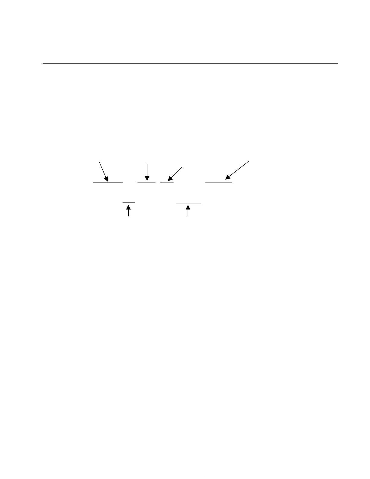
1.1 Option Designations
There are many options available for the MJ35 series fryer. When the fryer is equipped with these
additional features, suffixes are added to the model name to identify the options. The position of the
identifying letter is a factor in the option it identifies.
Here’s an example of how a MJ35 fryer’s options are revealed in the model name and a list of option
designators:
Indicates presence or
absence of a filter
Series designator
Indicates type,
placement of
controller
This position indicates
material used to construct
frypot, cabinet
MJ235GBLSC
Indicates number
of frypots in unit.
Indicates presence
of basket lifts
Possible filter position designators:
MJ: Master Jet (indicates there is no filter system with fryers)
FM: Filter Magic filter system in separate cabinet banked with fryer
FP: Footprint filtration under the fryer
F: Fryer is configured for attachment to existing filter system
Possible frypot number designators:
1 or no additional number before the series designation: Single frypot
2: Two fryers banked together
3: Three fryers banked together
4: Four fryers banked together
5: Five fryers banked together
6: Six fryers banked together
Possible controller designators:
G: Thermostat control on front panel
V: Thermostat controls located behind cabinet door
Blank, no designator here: Standard control behind front panel
1-1
35 SERIES GAS FRYERS
CHAPTER 1: GENERAL INFORMATION
Possible basket lift designators:
No text in this position: No basket lift system
BL: Fryer equipped with motorized basket lift
Possible frypot, cabinet material designators:
SC: Stainless steel vat, door and cabinet
SD: Stainless steel vat and door painted cabinet
SE: Stainless steel vat, door, cabinet and sides
SP: Stainless steel vat, painted door and cabinet
ST: Cold-rolled steel vat, painted door and cabinet
SX: Cold-rolled steel vat, stainless steel door and painted cabinet
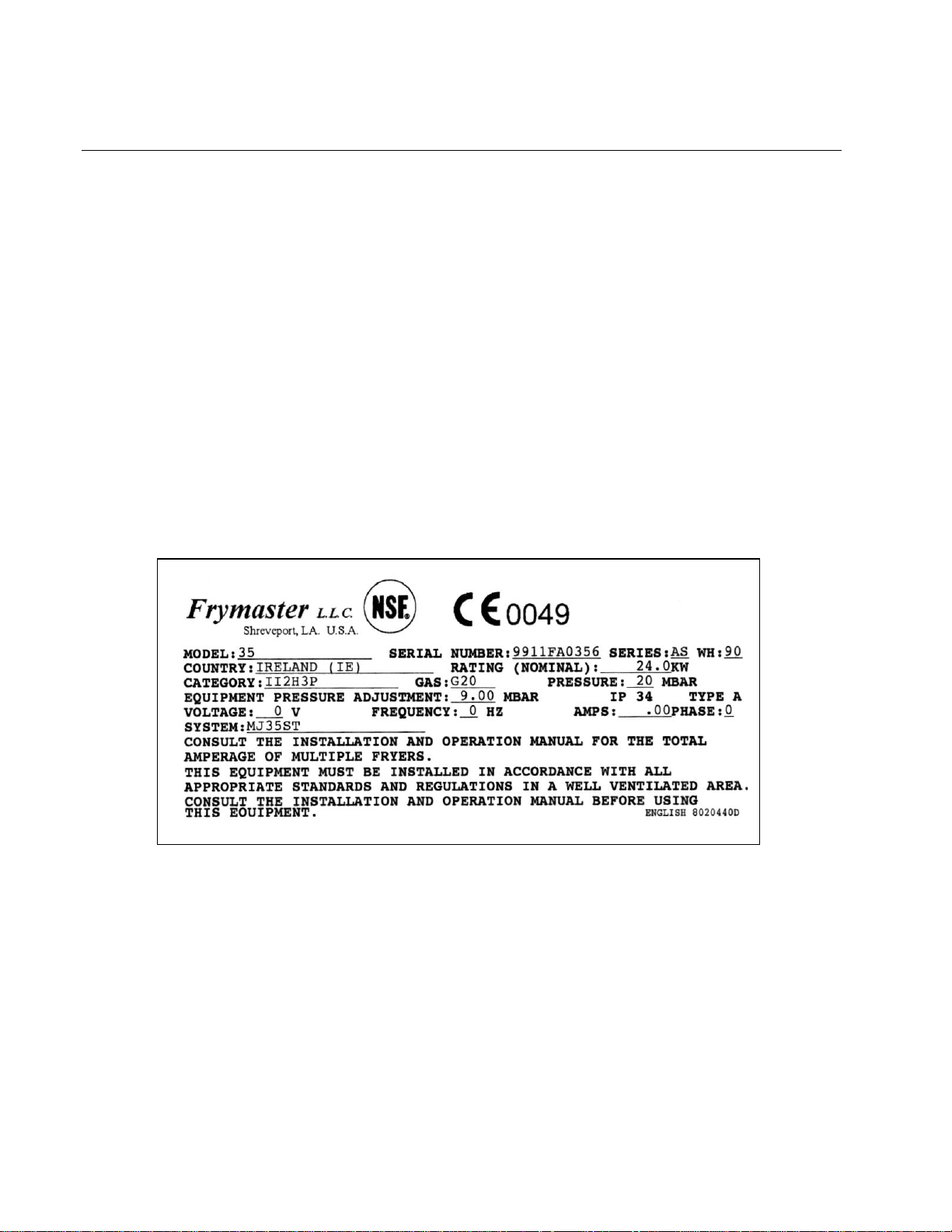
1.2 Rating Plate
1-2

35 SERIES GAS FRYERS
CHAPTER 1: GENERAL INFORMATION
1.3 Parts Ordering and Service Information
In order to assist you as quickly as possible, the Frymaster Factory Authorized Service Center
(FASC) or Service Department representative requires certain information about your equipment.
Most of this information is printed on a data plate affixed to the inside of the fryer door.
Parts orders must be placed directly with your local FASC or distributor. Included with fryers when
shipped from the factory is a list of Frymaster FASCs. If you do not have access to this list, contact
the Frymaster Technical Service Department at 1-800-551-8633 or 1-318-865-1711.
When ordering parts, the following information is required:
Model Number:
Serial Number:
Type of Gas or Voltage:
Item Part Number:
Quantity Needed:
Service information may be obtained by contacting your local FASC. Information may also be
obtained by calling the Frymaster Technical Service Department at 1-800-551-8633 or 1-318-865-
1711.
When requesting service, please have the following information ready:
Model Number:
Serial Number:
Type of Gas:
In addition to the model number, serial number, and type of gas, please be prepared to describe the
nature of the problem and have ready any other information that you think may be helpful in solving
your problem.
RETAIN AND STORE THIS MANUAL IN A SAFE PLACE FOR FUTURE USE.
1.4 Safety Information
Before attempting to operate your unit, read the instructions in this manual thoroughly.
Throughout this manual, you will find notations enclosed in double-bordered boxes similar to the
ones below.
CAUTION
boxes contain information about actions or conditions that may cause or result in a
malfunction of your system.
CAUTION
1-3
35 SERIES GAS FRYERS
CHAPTER 1: GENERAL INFORMATION
Example of a CAUTION box.
WARNING
boxes contain information about actions or conditions that may cause or result in dam-
age to your system, and which may cause your system to malfunction.
WARNING
Example of a WARNING box.
DANGER boxes contain information about actions or conditions that may cause or result in injury to
personnel, and which may cause damage to your system and/or cause your system to malfunction.
DANGER
Hot cooking oil or shortening causes severe burns. Never attempt to move a fryer
containing hot cooking oil/shortening or to transfer hot cooking oil/shortening from
one container to another.
Your fryer is equipped with automatic safety features:
1. High temperature detection shuts off gas to the burner assembly if the controlling thermostat
fails.
2. A safety switch built into the drain valve of units with built-in filtration systems prevents burner
ignition with the drain valve even partially open.
1.5 European Community (CE) Specific Information
The European Community (CE) has established certain specific standards regarding equipment of
this type. Whenever there is a difference between CE and non-CE standards, the information or instructions concerned are identified by boxes similar to the one below.
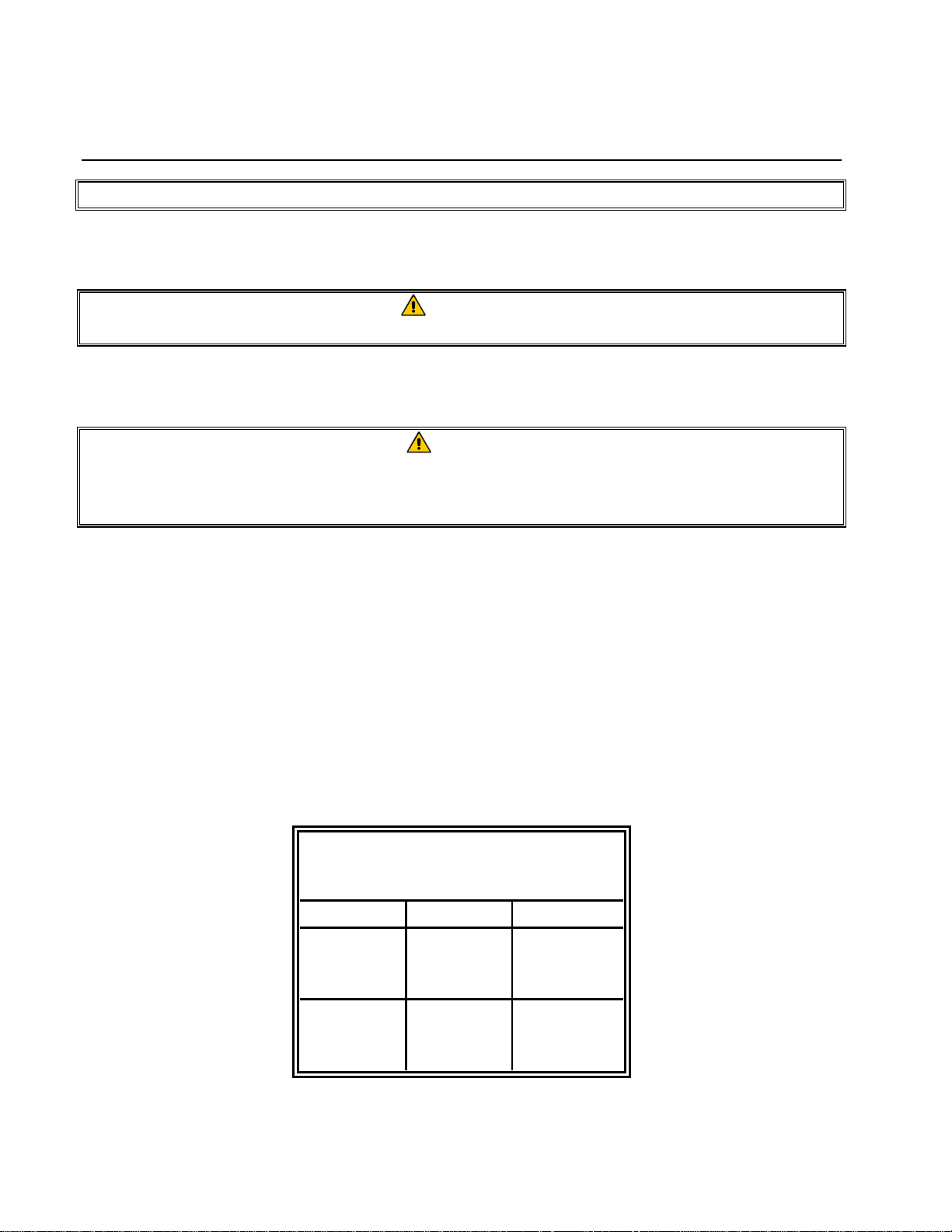
Non-CE Standard
for Incoming Gas Pressures
Gas Minimum Maximum
Natural
LP
6" W.C.
1.49 kPa
14.93 mbar
11" W.C.
2.74 kPa
27.37 mbar
14" W.C.
3.48 kPa
34.84 mbar
14" W.C.
3.48 kPa
34.84 mbar
1-4

35 SERIES GAS FRYERS
CHAPTER 1: GENERAL INFORMATION
1.6 Equipment Description
35 Series gas fryers are designed for all-purpose frying. Models include MJ35, MJ35G, MJ35GBL
and FM35G. Fryers in this series may be equipped with basket lifts and in banks of up to six with a
Filter Magic filtration systems or configured for manual filtration (MJ35, MJ35G and MJ35GBL
variants). The J2X model is a variant that has no cabinetry. It is designed for “drop-in” installations.
35 Series fryers use a millivolt temperature control circuit, which requires no external power. The
MJ35GBL, which has automatic basket lifts, can be configured with 120V or 240V motors.
All models are of an open-pot design with no tubes and have a hand-sized opening into the deep cold
zone, which makes cleaning the stainless frypot quick and easy.
Fryers equipped with built-in filtration systems are shipped completely assembled. Fryers without
built-in filtration require installation of legs or optional casters at point of use. All fryers are shipped
with a package of standard accessories. Each fryer is adjusted, tested, and inspected at the factory
before crating for shipment.
Frypots are constructed of welded, heavy-gauge stainless steel or cold-rolled steel. Heating is supplied by a burner assembly having multiple gas jets, which are focused on ceramic targets located
around the lower side of the frypot. The burner assembly can be configured for natural gas, propane,
or manufactured gas, as required by the customer. A drain is tapped into the center of the frypot,
with a front-controlled manual ball valve.
Each fryer is equipped with a thermostat probe for precise temperature control. The thermostat is
located on the centerline of the frypot for rapid response to changes in loads and to provide the most
accurate temperature measurement.
1.7 Installation, Operating, and Service Personnel
Operating information for Frymaster equipment has been prepared for use by qualified and/or authorized personnel only, as defined in Section 1.6.
All installation and service on Frymaster equipment must be performed by qualified, certified,
licensed, and or/authorized installation or service personnel, as defined in Section 1.6.
1.8 Definitions
QUALIFIED AND/OR AUTHORIZED OPERATING PERSONNEL
Qualified/authorized operating personnel are those who have carefully read the information in this
manual and have familiarized themselves with the equipment functions, or who have had previous
experience with the operation of the equipment covered in this manual.
1-5

35 SERIES GAS FRYERS
CHAPTER 1: GENERAL INFORMATION
QUALIFIED INSTALLATION PERSONNEL
Qualified installation personnel are individuals, or firms, corporations, or companies which, either in
person or through a representative, are engaged in and are responsible for the installation of gasfired appliances. Qualified personnel must be experienced in such work, be familiar with all gas
precautions involved, and have complied with all requirements of applicable national and local
codes.
QUALIFIED SERVICE PERSONNEL
Qualified service personnel are those that are familiar with Frymaster equipment and who have been
authorized by
sonnel are required to be equipped with a complete set of service and parts manuals and stock a prescribed minimum amount of Frymaster equipment parts.
A list of Frymaster Factory Authorized Service Centers (FASC) is included with the fryer when it
ships from the factory. Failure to use qualified service personnel will void the Frymaster War-
ranty on your equipment.
Frymaster
to perform service on Frymaster equipment. All authorized service per-
1.9 Shipping Damage Claim Procedure
Your Frymaster equipment was carefully inspected and packed before leaving the factory. The
transportation company assumes full responsibility for safe delivery upon acceptance of the equipment for transport.
What to do if your equipment arrives damaged:
1. File a claim for damages immediately, regardless of the extent of damages.
2. Inspect for and record all visible loss or damage, and ensure that this information is noted on
the freight bill or express receipt and is signed by the person making the delivery.
3. Concealed loss or damage that was unnoticed until the equipment was unpacked should be re-
corded and reported to the freight company or carrier immediately upon discovery. A concealed
damage claim must be submitted within 15 days of the date of delivery. Ensure that the shipping
container is retained for inspection.
Frymaster
RESPONSIBILITY FOR DAMAGE OR LOSS
DOES NOT ASSUME
INCURRED IN TRANSIT.
1-6

35 SERIES GAS FRYERS
CHAPTER 2: INSTALLATION INSTRUCTIONS
2.1 General Installation Requirements
PROPER INSTALLATION IS ESSENTIAL FOR EFFICIENT, TROUBLE-FREE OPERATION OF YOUR
FRYER. ANY UNAUTHORIZED ALTERATIONS MADE TO THIS EQUIPMENT WILL VOID THE
FRYMASTER
Upon arrival, inspect the fryer carefully for visible or concealed damage. (See Shipping Damage
Claim Procedure in Chapter 1.)
CLEARANCE AND VENTILATION
The fryer(s) must be installed with a 6” (150 mm) clearance at both sides and back when installed
adjacent to combustible construction; no clearance is required when installed adjacent to noncombustible construction. A minimum of 24” (600 mm) clearance should be provided at the front of the
fryer.
One of the most important considerations of efficient fryer operation is ventilation. Make sure the
fryer is installed to efficiently remove combustion by-products, and the kitchen ventilation system
does not produce drafts that interfere with proper burner operation.
The fryer flue opening must not be placed close to the intake of the exhaust fan, and the fryer must
never have its flue extended in a “chimney” fashion. An extended flue will change the combustion
characteristics of the fryer, causing longer recovery time. It also frequently causes delayed ignition.
To provide the airflow necessary for good combustion and burner operation, the areas surrounding
the fryer front, sides, and rear must be kept clear and unobstructed.
Fryers must be installed in an area with an adequate air supply and adequate ventilation. Adequate
distances must be maintained from the flue outlet of the fryer to the lower edge of the ventilation
filter bank. Filters should be installed at an angle of 45º. Place a drip tray beneath the lowest edge
of the filter. For U.S. installation, NFPA standard No. 96 states, “A minimum distance of 18 in.
(450 mm) should be maintained between the flue outlet and the lower edge of the grease filter.”
Frymaster recommends that the minimum distance be 24 in. (600 mm) from the flue outlet to the bot-
tom edge of the filter when the appliance consumes more than 120,000 BTUs per hour.
Information on construction and installation of ventilating hoods can be found in the NFPA standard
cited above. A copy of the standard may be obtained from the National Fire Protection Association,
Battery March Park, Quincy, MA 02269.
WARRANTY.
DANGER
Do not attach an apron drainboard to a single fryer. The fryer may become unstable,
tip over, and cause injury. The appliance area must be kept free and clear of com-
bustible material at all times.
2-1

35 SERIES GAS FRYERS
CHAPTER 2: INSTALLATION INSTRUCTIONS
NATIONAL CODE REQUIREMENTS
The type of gas for which the fryer is equipped is stamped on the data plate attached to the inside of
the fryer door. Connect a fryer stamped “NAT” only to natural gas, those stamped “PRO” only to
propane gas, and those stamped “MFG” only to manufactured gas.
Installation shall be made with a gas connector that complies with national and local codes, and,
where applicable, CE codes. Quick-Disconnect devices, if used, shall likewise comply with national, local, and, if applicable, CE codes.
ELECTRICAL GROUNDING REQUIREMENTS
All electrically operated appliances must be grounded in accordance with all applicable national and
local codes, and, where applicable, CE codes. A wiring diagram is located on the inside of the fryer
door. Refer to the rating plate on the inside of the fryer door for proper voltages.
DANGER
If this appliance is equipped with a three-prong (grounding) plug, it must be plugged
directly into a properly grounded receptacle.
Do not cut or remove the grounding prong from the plug.
2.2 Caster/Leg Installation
Depending upon the specific configuration ordered, your fryer may have been shipped without installed casters or legs. If casters or legs are installed, you may skip this section and proceed to Section 2.3, Pre-Connection Preparations. Fryers must have castors or legs. Fryers cannot be curb
mounted.
Install the casters/legs in accordance with the instructions included in your accessory package.
2.3 Pre-Connection Preparations
DANGER
Do not connect fryer to gas supply before completing each step
in this section.
After the fryer has been positioned under the fry station exhaust hood, ensure the following has been
accomplished:
1. Adequate means must be provided to limit the movement of fryers without depending upon the
gas line connections. If a flexible gas hose is used, a restraining cable must be connected at all
2-2
 Loading...