

Page 1
1814E with FilterQuick™
Electric Fryer
Parts Manual
This manual is updated as new information and models are released. Visit our website for the latest manual.
*8197319*
Part Number: FRY_P_8197319 11/2016
Page 2
NOTICE
IF, DURING THE WARRANTY PERIOD, THE CUSTOMER USES A PART FOR THIS MANITOWOC FOOD SERVICE
EQUIPMENT OTHER THAN AN UNMODIFIED NEW OR RECYCLED PART PURCHASED DIRECTLY FROM
FRYMASTER, OR ANY OF ITS FACTORY AUTHORIZED SERVICERS, AND/OR THE PART BEING USED IS
MODIFIED FROM ITS ORIGINAL CONFIGURATION, THIS WARRANTY WILL BE VOID. FURTHER, FRYMASTER
DEAN AND ITS AFFILIATES WILL NOT BE LIABLE FOR ANY CLAIMS, DAMAGES OR EXPENSES INCURRED BY
THE CUSTOMER WHICH ARISE DIRECTLY OR INDIRECTLY, IN WHOLE OR IN PART, DUE TO THE
INSTALLATION OF ANY MODIFIED PART AND/OR PART RECEIVED FROM AN UNAUTHORIZED SERVICER.
NOTICE
This appliance is intended for professional use only and is to be operated by qualified personnel only. A
Factory Authorized Servicer (FAS) or other qualified professional should perform installation,
maintenance, and repairs. Installation, maintenance, or repairs by unqualified personnel may void the
manufacturer’s warranty.
DANGER
Improper installation, adjustment, maintenance or service, and unauthorized alterations or
modifications can cause property damage, injury, or death. Read the installation, operating, and service
instructions thoroughly before installing or servicing this equipment.
DANGER
The front ledge of this appliance is not a step! Do not stand on the appliance. Serious injury can result
from slips or contact with the hot oil.
WARNING
Do not attach accessories to this fryer unless fryer is secured from tipping. Personal injury may result.
DANGER
Adequate means must be provided to limit the movement of this appliance without depending on or
transmitting stress to the electrical conduit. A restraint kit is provided with the fryer. If the restraint kit is
missing contact your local KES.
DANGER
Prior to movement, testing, maintenance and any repair on your Frymaster fryer, disconnect all electrical
power from the fryer.
i
Page 3

1814E with FILTERQUICK™ SERIES ELECTRIC FRYERS PARTS
TABLE OF CONTENTS
CAUTIONARY STATEMENTS ........................................................................................................................................................ i
CHAPTER 1: Parts List
1.1 Accessories ................................................................................................................................................................. 1-1
1.1.1 1814E FilterQuick PCB/Controller Board Matrix ........................................................................ 1-1
1.2 Doors, Sides, Tilt Housings, Top Caps, Casters and Other Exterior Components ............................. 1-2
1.3 Electronics and Wiring Components ................................................................................................................ 1-3
1.3.1 Component Boxes ............................................................................................................................... 1-3
1.3.2 Contactor Boxes.................................................................................................................................... 1-4
1.3.3 Heating Element Assemblies and Associated Parts ................................................................. 1-5
1.3.3.1 Element Assemblies and Hardware ............................................................................. 1-5
1.3.3.2 Element Tube Assemblies ............................................................................................... 1-6
1.3.4 Wiring ....................................................................................................................................................... 1-6
1.3.4.1 Contactor Box Wiring Assemblies 12-Pin Full Vat .................................................. 1-6
1.3.4.2 Contactor Box Wiring Assemblies 6-Pin Left Element .......................................... 1-7
1.3.4.3 Contactor Box Wiring Assemblies 9-Pin Right Element ....................................... 1-7
1.3.4.4 Component Box to Filter Pump Harness ................................................................... 1-7
1.3.4.5 Main Wiring Harness ......................................................................................................... 1-8
1.3.4.6 Interface Board to Controller Wiring Harness 15-Pin ............................................ 1-8
1.3.4.7 Component Box, Filter Pump and Basket Lift Wiring Harnesses ...................... 1-9
1.3.4.8 Basket Lift Harness ............................................................................................................. 1-9
1.4 Filtration System Components ........................................................................................................................ 1-10
1.4.1 Filter Pan and Associated Components .................................................................................... 1-10
1.4.2 Filter Pump and Associated Components ............................................................................... 1-11
1.5 Filtration Electronic Components ................................................................................................................... 1-12
1.5.1 Manual Interface Board (MIB) Assembly ................................................................................... 1-12
1.5.2 Automatic Intermittent Filtration (AIF) Board Assembly .................................................... 1-12
1.6 Frypot Assemblies and Associated Parts ...................................................................................................... 1-13
1.7 Auto Top-Off Pump Assembly ......................................................................................................................... 1-14
1.8 Oil Plumbing Components ................................................................................................................................ 1-15
1.8.1 Bulk Manifold and Accessories ..................................................................................................... 1-15
1.8.2 Bulk Dispose Waste Valve .............................................................................................................. 1-16
1.8.3 Bulk Connection ................................................................................................................................ 1-17
1.8.4 Oil Quality Sensor (OQS) and Associated Parts ...................................................................... 1-17
1.9 Basket Lift Assembly and Associated Parts .................................................................................................. 1-18
1.10 Wiring Connectors, Pin Terminals and Power Cords ............................................................................... 1-20
1.11 Fasteners .................................................................................................................................................................. 1-21
1.12 Wiring Diagram for Harness Part Numbers ................................................................................................ 1-22
ii
Page 4
1814E with FILTERQUICK™ SERIES ELECTRIC FRYERS
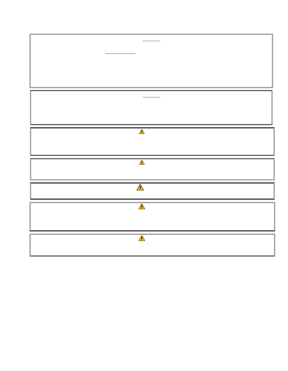
1.1 Accessories
CHAPTER 1: PARTS LIST
ITEM PART # COMPONENT
1 8030278 Brush, Frypot
2 8030388 Fryers Friend
3 8030446 Skimmer
4 1069620 Cover, Frypot 1817
5 8030380 Rack, Basket 1817
6 8030440 Fryer Scrubber Tool
7 8030439 Pad, Scrubber (For use with item #6)
8 8260900 Kit, Chain Restraint
9 8238155 Guard, Splash 1817
10 8030254 Brush, UHC (Oil Saddle Reservoir Cleaning Brush)
* 8030002 Powder, Filter (80- 1-Cup Applications)
* 8030170 Pack, 100-Sheet Filter Paper 27.5 X 19.5
* Not illustrated
1.1.1 1814E FilterQuick™ PCB/Controller Board Matrix
PART # COMPONENT
1087002 Assembly, MIB PCB w/ metal work see section 1.5.1
1085721 Assembly, AIF Board w/ metal frame see section 1.5.2
1085717 Board, ATO PCB w/ software see section 1.3.1
8263301 FQ3000 Controller Generic see section 1.2
1087077 FQ3000 Controller Cracker Barrel see section 1.2
1-1
Page 5
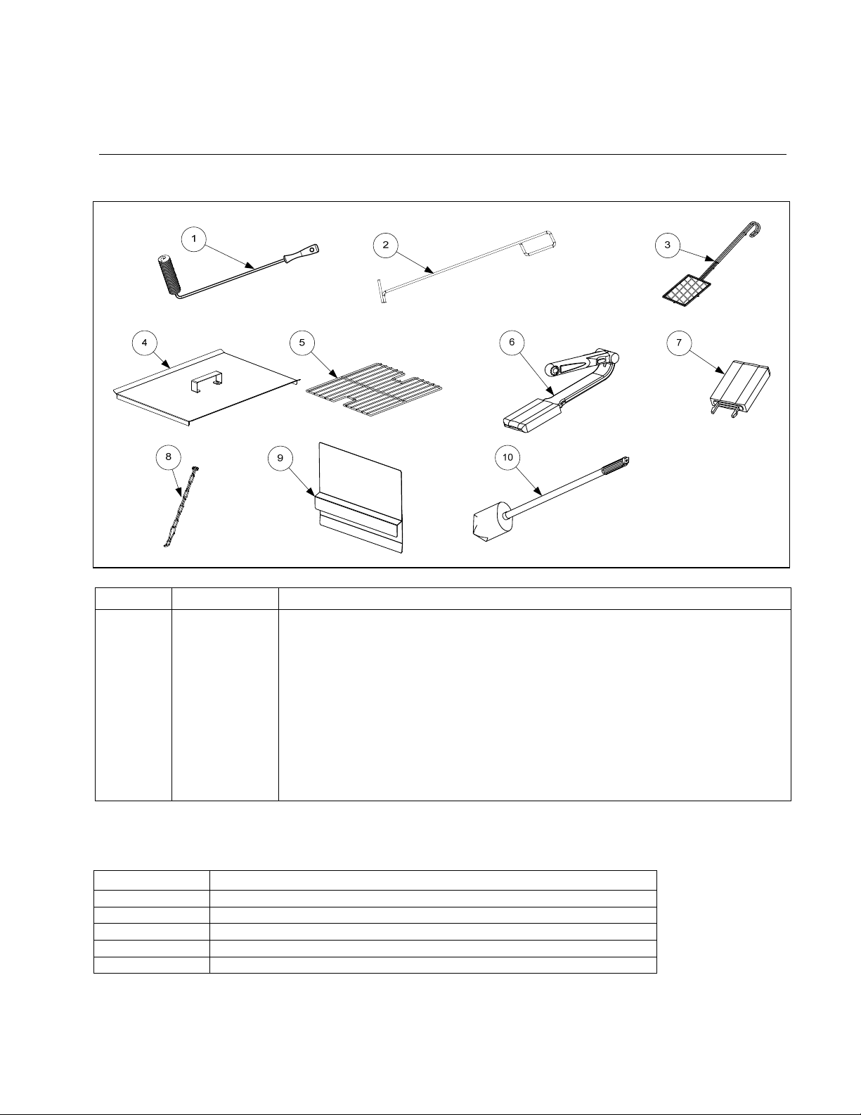
1.2 Doors, Sides, Tilt Housings, Top Caps, Casters and Other Exterior Components
√
T
√
√
ITEM PART # COMPONENT
1 2601516 Side, Cabinet Left FQ1814 SS
* 2601517 Side, Cabinet Right FQ1814 SS
2 2601519 Cover, Cabinet Side Hole
3 8075858 Switch, Push Button LED Blue Ring Light
4 1087031 Door, FQ1814 with Menu Holder
5 2108077 Handle, Door
* 1064067 Pin Assembly, Door
* 8100275 Spring, Door Pin
* 8100658 Retaining Ring
* 8121328 Hinge, Door Lower
* 2401407 Holder, 1814 Manual
* 8101105 Magnet, Door (vertical)
6 2304318 Hanger, Basket Single 1817
7 8100327 Caster 4” without Brake -Rear
8 8232844 Caster 3” with Brake -Front
9 8236716 Tilt Housing
10 1081722 Top Cap
11 2601520 Bezel, Controller FQ1814
12 8239210 Tank, Oil Saddle FQ1814
13 8239211 Lid, Oil Saddle Tank FQ1814
14 8130022 Nipple, ½“ x Close NP
15 8100490 Quick Disconnect ½“ Female
16 8263301 Controller, Replacement FilterQuick™
1087077 Controller, Replacement FilterQuick™ Cracker Barrel
* 2204317 Back, Lower Cabinet
* 2401464 Back, Upper Cabinet
* Not illustrated
√ Recommended parts
1-2
Page 6
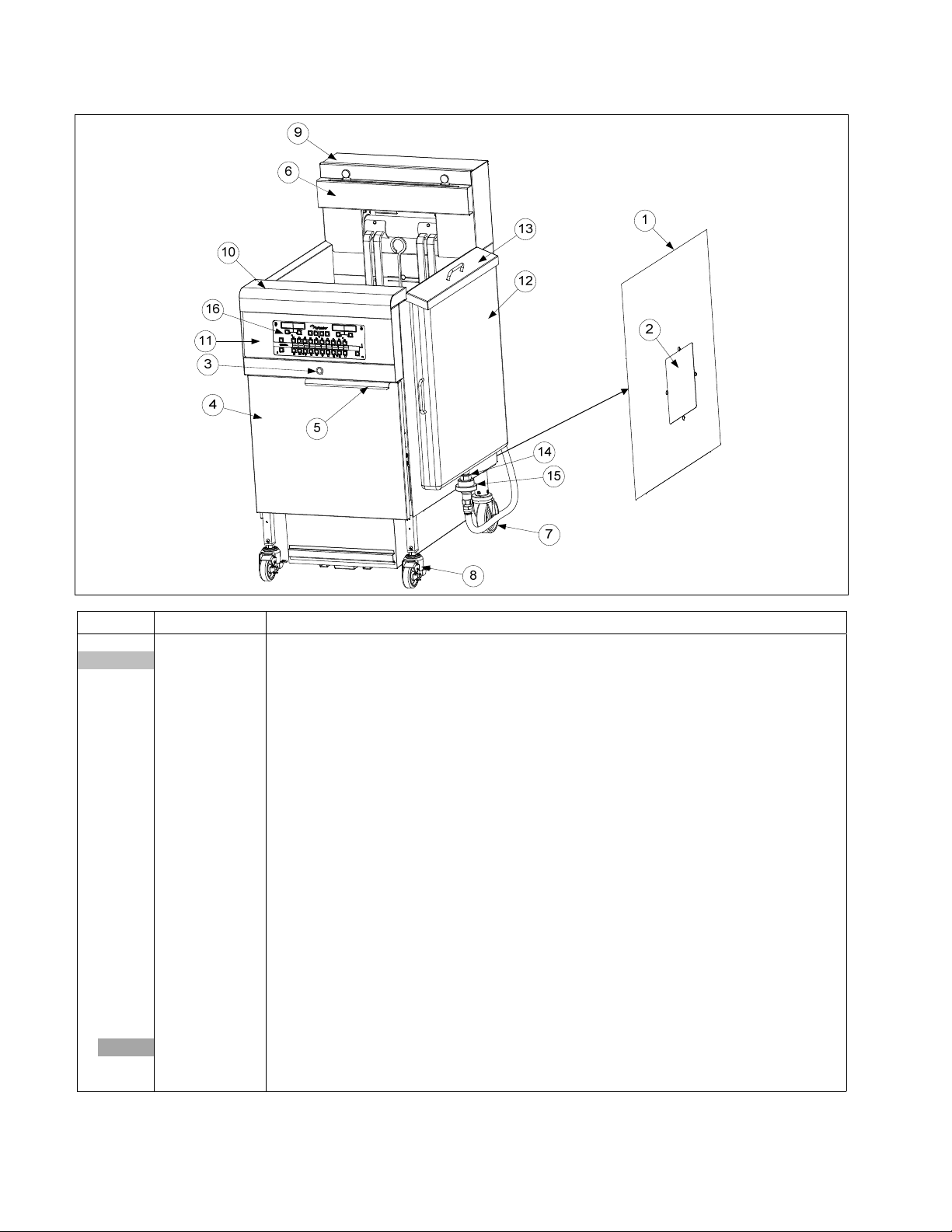
1.3 Electronics and Wiring Components
√
√
√
√
√
√
T
√
T
√
T
√
T
√
√
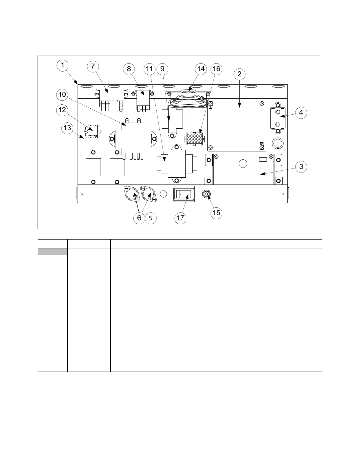
1.3.1 Component Boxes
ITEM PART # COMPONENT
1087001 Box Assembly, Component 208-240V
1 1086997 Box Stud Assembly, Component
2 8262260 Interface Board, Standard Full or Dual Vat (includes sound harness)
3
1085717
4 8070012 Relay, 18AMP 1/3 HP 24V Coil (Top off pump)
5 8071321 Holder, AGC Panel Mount ¼” Fuse
6 8072278 Fuse, 20 AMP
7 8074482 Relay, Filter 2 Pole 30A DPDT 24VDC
8 8075623 Relay, 24VDC SPD
9 8070979
10 8075362
11 8070680
12 8101164 Terminal Block
13 8160217 Paper, Insulating Terminal Block
14 8074403 Speaker, 4-Watt SMT
15 8074678 Switch, Momentary Flush JIB Reset
16 1065750 Harness Assembly, RE FV Controls
17 8074036 Switch, Power
* 8262249 RE Hood/Ansul Interlock Kit (includes terminal block, wires and connectors)
* Not illustrated
√ Recommended parts
PCB Board, Automatic Top Off
ransformer, 208-240V/12V 43VA Controller and ATO Board Power
ransformer, 115-240V/24V 80VA MIB, AIF and ATO Pump
ransformer, 208/240V/24V 20VA Heat/Latch Contactor, ATO board
1-3
Page 7
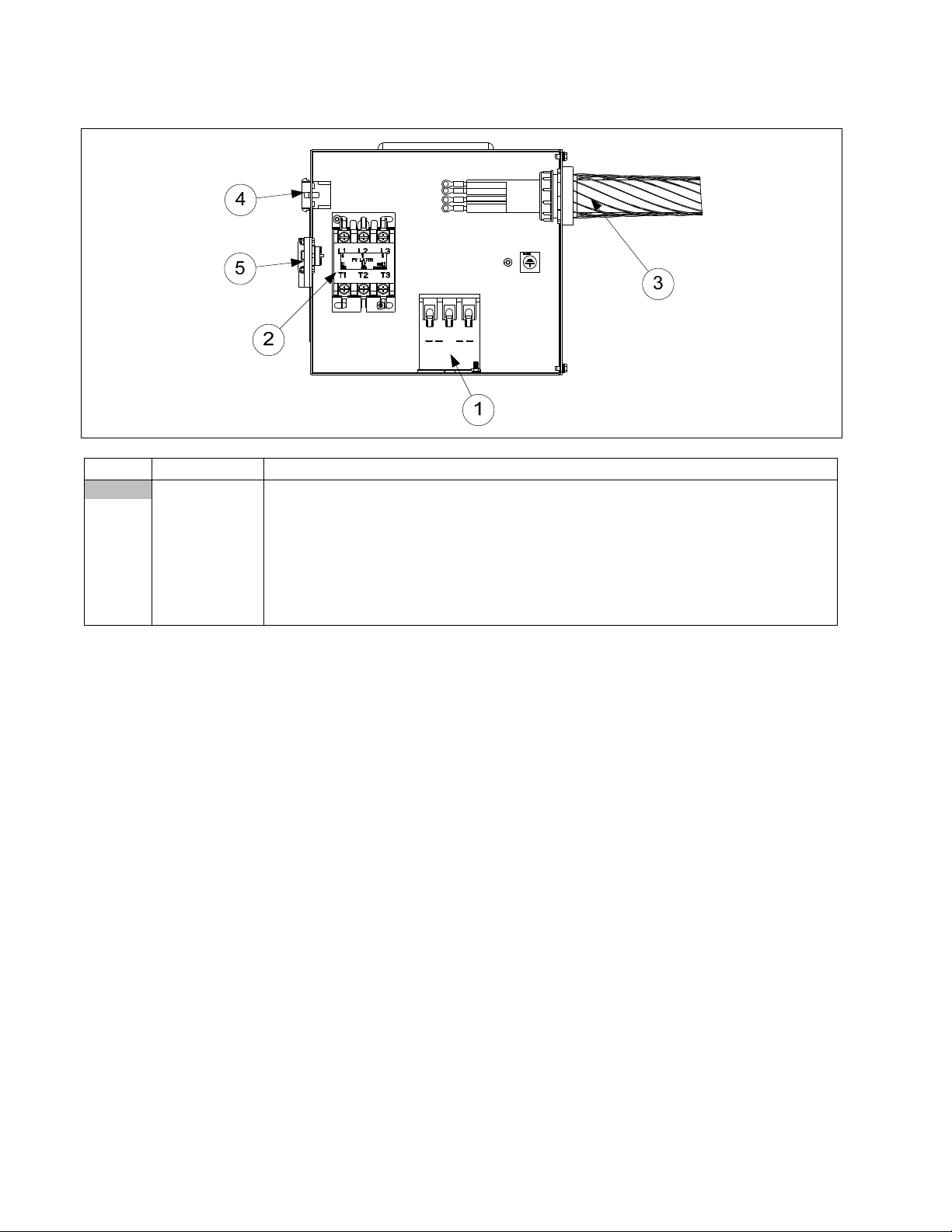
1.3.2 Contactor Box
√
√
f
ITEM PART # COMPONENT
1086999 Box, Contactor Assembly 1814FQ Delta
1 8072284
2 8101202
3 8075625 Cord Set, 4 Gauge, 4 Wire with Strain Relie
4 1066031 Harness Assembly, RE FV Contactor Box Control
5 1080158 Harness Assembly, 208/240V Contactor Box Power
* 1068932 Bracket Assembly, Element Mounting
* 2401440 Cover, Contactor Box
* Not illustrated
√ Recommended parts
Contactor, 24V Coil 50 Amp Mechanical (Heat)
Contactor, 24V 40 Amp Mechanical (Latch)
1-4
Page 8
1.3.3 Heating Element Assemblies and Associated Parts
√
1.3.3.1 Element Assemblies and Hardware
ITEM PART # COMPONENT
1 Element Kits – includes gaskets, grommets, tie wraps, screws and nuts.
8262557 208V 8.5 kW
8262707 230V 8.5 kW
8262558 240V 8.5kW
2 8262652 Probe, Temperature RE1817, 1814 – includes tie wraps and grommet.
3 8160681 Grommet, Probe
4 8160480 Plug, .375-inch Dome
5 8160688 Gasket, Element
6 8091003
* 8090766 Nut, 10-32 Keps Hex Head SS
* 2304028 Wrench, Element Tube Nut Spanner
7 2300784 Bracket, Temperature Probe 8.5 kW (17kW)
8 8090518
9 9102042 Clamp, Element (Short)
10 2300781 Clamp, Element (Long)
11 2304902 Support, Full-Vat Element Rear
12 8236711 Bracket, Element 1814
13 8090567 Tie-Wrap, Metal
14 8101212 Pin, .125 X .50-inch Slotted
15 8103030 Spring, Element Lift Left
8103031 Spring, Element Lift Right
16 2204302 Bracket, Lower Spring
17 8101233 Handle, Element Lift
√ Recommended parts
Screw, 10-32 X ⅜-inch Hex Head SS
Screw, 8-32 X ⅜-inch Slotted Hex Head
1-5
Page 9

1.3.3.2 Element Tube Assemblies
FULL-VAT ELEMENT TUBE ASSEMBLY
1
6
7
2
8
3
4
ITEM PART # COMPONENT
1 1080293 Tube Assembly, Full-Vat 17 kW
2 8102992 Tube, Full Vat Element Mounting
3 8102993 Bushing, Tube End Teflon
4 1080315 Bracket Assembly, LH Element Tube Support
5 1080316 Bracket Assembly, RH Element Tube Support
6 2200122 Plate, Element Tube Support Inner
7 2200123 Plate, Element Tube Support Outer
8 1066569 Bracket Assembly, LH Upper Spring
9 1066570 Bracket Assembly, RH Upper Spring
* 8262598 Kit, Tilt Switch
* 8074742 Switch, Long Lever High Temp
* Not illustrated
1.3.4 Wiring
1.3.4.1 Contactor Box Wiring Assemblies – 12-Pin Full-Vat C-1
9
5
1
2
3
4
5
1
6
7
8
9
10
11
12
GREEN/YELLOW 75C
BLUE 74C
ORANGE 76C
ORANGE 71C
ITEM PART # COMPONENT
1066031SP Contactor Box Harness Assembly Full Vat
1 Standard
1-6
Page 10

1.3.4.2 Contactor Box Wiring Assembly – 6-Pin (Left Element)
ITEM PART # COMPONENT
1 1068744SP 14/17 kW Mechanical Contactor
1.3.4.3 Contactor Box Wiring Assembly – 9-Pin (Right Element)
ITEM PART # COMPONENT
1 1068745SP 14/17 kW Mechanical Contactor
1.3.4.4 Component Box to Filter Pump Harness
1-7
Page 11

1.3.4.5 Main Wiring Harness
1.3.4.6 Interface Board to Controller Wiring Harness – 15-Pin
PN 8074199
SMT Controller to Interface
Board Wiring Harness
1-8
Page 12

1.3.4.7 Component Box, Filter Pump and Basket Lift Wiring Harnesses
ITEM PART # COMPONENT
1 1065750SP
2 1080490 Filter Pump C2 to Component Box Wiring Harness
3 1065962SP
1.3.4.8 Basket Lift Harness
Full Vat Control Harness J4 to J2 (Standard)
Basket Lift Harness Assembly (Standard)
1-9
Page 13

1.4 Filtration System Components
√
√
1.4.1 Filter Pan and Associated Components
ITEM PART # COMPONENT
1 8239205 Lid, Filter Pan Fixed
1087029SP Pan, Filter Assy (includes items 2-10)
2 8239230 Crumb Tray
3 8103414 Hold-Down Ring 13.85 x 20.80
4 2204446 Sana Grid Filter Screen
5 8239209 Pan, Filter with casters
6 8263288 O-Ring (Pkg. of 6; used with Item 5)
7 8130568
8 8238335 Screen, Suction Line Filter
9 8122337 Caster, 2” Rigid
10 8103007 Magnet, Pull Ring
11 1087010 Assembly, Filter Pan Switch
* 1065876SP Sensor, Magnet
12 8239201 Suction Tube
13 2401449 Support, Left Filter Pan
14 2401450 Support, Right Filter Pan
Plug, ⅛” Socket Head Pipe (used with Item 5; two required)
* Not illustrated
√ Recommended parts
1-10
Page 14

1.4.2 Filter Pump and Associated Components
√
Pump plumbing may differ
somewhat from illustration
depending on configuration
and date of manufacture.
Intake from
filter pan or
OQS sensor
Discharge from
filter pump to
return manifold
ITEM PART # COMPONENT
1 Motor and Gasket Kit
8261785 100V 50/60 Hz
8261712 115V 50/60 Hz
8261756 208V 50/60 Hz
8261270 220-240V 50/60 Hz
8261755 250V 50/60 Hz
2 8263192 Pump and Gasket Kit, 8 GPM
8160093 Gasket, Pump/Motor
3 8091062 Cap Screw, 5/16”-18 5.50” NC Hex (Connects pump to motor)
4 8090194 Washer, Flat 5/16”
5 8130763 Bushing, ¾” OD x ½” ID NPT Flush
6 8130022 Nipple, ½” x Close NPT BM
7 8130062 Elbow, ½” 90° BM
8 8101668
9 8101067
10 8101068
* 1065912SP Heater Strip Assembly, 208-250V 25W 18”
* Not illustrated
√ Recommended parts
Adapter, ⅝” to ½” NPT Male
Flexline, ⅝” OD x 8.50-inch Oil Return (to filter suction tube or OQS sensor if applicable)
Flexline, , ⅝” OD x 21.50-inch Oil Return (to oil return manifold)
1-11
Page 15

1.5 Filtration Electronic Components
√
1.5.1 Manual Interface Board (MIB) Assembly
ITEM PART # COMPONENT
1 2401445 Cover, 1814FQ MIB
2 8091021 Screw, 10 x 3/8” Torx Pan
3 1085772 Assembly, MIB w/ Frame
8074481 Overlay
4 2401444 Bracket, 1814FQ MIB Mounting
√ Recommended parts
1087002
Assembly, MIB 1814FQE
1.5.2 Automatic Intermittent Filtration (AIF) Board Assembly
1087002 Manual
Interface Board
Assembly
1085721 AIF Board Assembly
ITEM PART # COMPONENT
√
1 8241991 Cover, AIF Board
2 8160814 Gasket, AIF Board
3 8160815 Gasket, Computer Board
4 1085720 Board, AIF
5 8160820 Seal, AIF Board
6 1080097 Panel Assembly, AIF Box
√ Recommended parts
1085721
Assembly, AIF
1-12
Page 16

1.6 Frypot Assemblies and Associated Parts
√
T
√
√
√
√
√
ITEM PART # COM P O NENT
1 1087034 Frypot, FQ1814
2
8262454 Non-CE Full Vat 425°F (218°C) (17kW FV and 14kW FV) (Color Coded Black 8067543)
8262455 CE Full Vat 415°F (213°C) (14kW and 17kW CE) (Color-Coded Yellow 8068132)
3 8262706 Probe, Kit AIF/ATO RTD
4 8074961 Actuator, Rotary 24VDC (#1) Blue
5 8074962 Actuator, Rotary 24VDC (#2) Black
6 8103798 Valve, 1½” Drain Rotary Actuator (Drain)
7 8239206 Drain, Spout 1814E
8 2401459 Strap, Drain FQ1814E
9 8130022 Nipple, ½” x Close NPT BM
10 8130062 Elbow, ½” Blk 90°
11 8103754 Valve, ½” NPT Rotary Actuator (Return)
12
8101668
13 8070128 Bushing Insulating Heyco
√ Recommended parts
hermostat Assembly, High-Limit Long Standard
Adaptor, Male ⅝” OD x ½”
1-13
Page 17

1.7 Auto Top-Off Pump Assembly
√
Intake
Discharge
ITEM PART # COMPONENT
1 1080639 Pump, Shurflo 24VAC
2 8104464 Flexline, ½” OD x 10-inch (Discharge to oil return manifold)
3 8103591 Flexline, ½” OD x 8-inch (In from bulk fresh oil solenoid)
4 8103666 Fitting, Shurflow Pump
5 8160782 O-Ring, Viton #111
6 8130940
√ Recommended parts
Elbow, ¼” NPT x ⅜” Flare
1-14
Page 18

1.8 Oil Plumbing Components
1.8.1 Bulk Manifold and Accessories
1-15
Page 19

1.8.1 Bulk Manifold and Accessories cont.
√
T
T
ITEM PART # COMPONENT
1 1066830 Solenoid Assembly
2 1080446 Valve, Bulk Waste Assembly (see section 1.8.2 for parts)
3 8101668
4 8103587 Lock and Key, RTI Waste Handle
5 8075786 Harness, Bulk Oil
6 8101057
7 8090601 Clip, Clevis Left Rod End
8 8101067
9 8130555 Reducer, Bell Fitting, ½” to ¼” NPT BM
10 8103531 Valve, Check 20 PSI RTI bypass
11 8100667 Valve, Check ½” NPT 1 PSI
12 8104495 Manifold, FQ1814E Bulk/Return
13 8130003 Tee, ½” x ½” x ½” BM
14 8103738 Adaptor, Check Valve Close Nipple
15 2205656 Brace, RTI Handle
16 2208664 Cover, Handle Lock
17 8130062 Elbow, ½” BM 90°
18 8239213 Handle, Bulk Waste
19 8130304 Bushing, ½” x ¼”
20 8130345 Elbow, ½ Blk 45°
21 8101055
22 8130838 Nipple, ¼” NP
23 8103583 Valve, Check ½” NPT 4 PSI
24 8130022 Nipple, ½” x close NPT BM
25 8103270 Fitting, 3/8” Flare x ¼” NP
26 8101669
√ Recommended parts
1.8.2 Bulk Dispose Waste Valve
Adaptor, Male ⅝” OD x ½”
Flexline, ⅝” OD x 13-inch long
Flexline, ⅝” OD x 8.50-inch long
Flexline, ⅝” OD x 11.50-inch long
Adaptor, Female ⅝” OD x ½”
ITEM PART # COMPONENT
1080446 Valve, Dispose Waste
1 1080445 Bracket, RTI Waste Valve
2 2205615 Handle, RTI Waste Valve
3 8074936 Microswitch, Gold Sealed
4 8100278 Valve, ½” Ball
5 9002935 Retainer, Nut Return Valve
6 9012348 Cover, DV Safety Switch
7 9022348 Cover, DV Safety Switch
1-16
Page 20

1.8.3 Bulk Connection
ITEM PART # COMPONENT
1 8100487 Coupling, Male Quick Disconnect
2 8101668
Adapter, ⅝” to ½” NPT Male
3 8103823 Hose
4 8130463 Plug, Pipe ½” NPT BM
5 8130616 Elbow, Street ½” x ½” NPT 90°
6 8239204 Mount, FQ1814E Oil Connection
1.8.4 Oil Quality Sensor (OQS) and Associated Parts
ITEM PART # COMPONENT
1 8263292 Sensor, FilterQuick OQS Replacement
2 8101055
Flexline, ⅝” OD x 11.5-inch
3 2401385 Retainer, OQS Sensor FQ
4 2401456 Mount, OQS Sensor FQ1814E
5 8104167 Lanyard, In-Line Filter
6 2401086 Wrench, Pre-Filter Cap
1-17
Page 21

1.9 Basket Lift Assembly and Associated Parts
1-18
Page 22

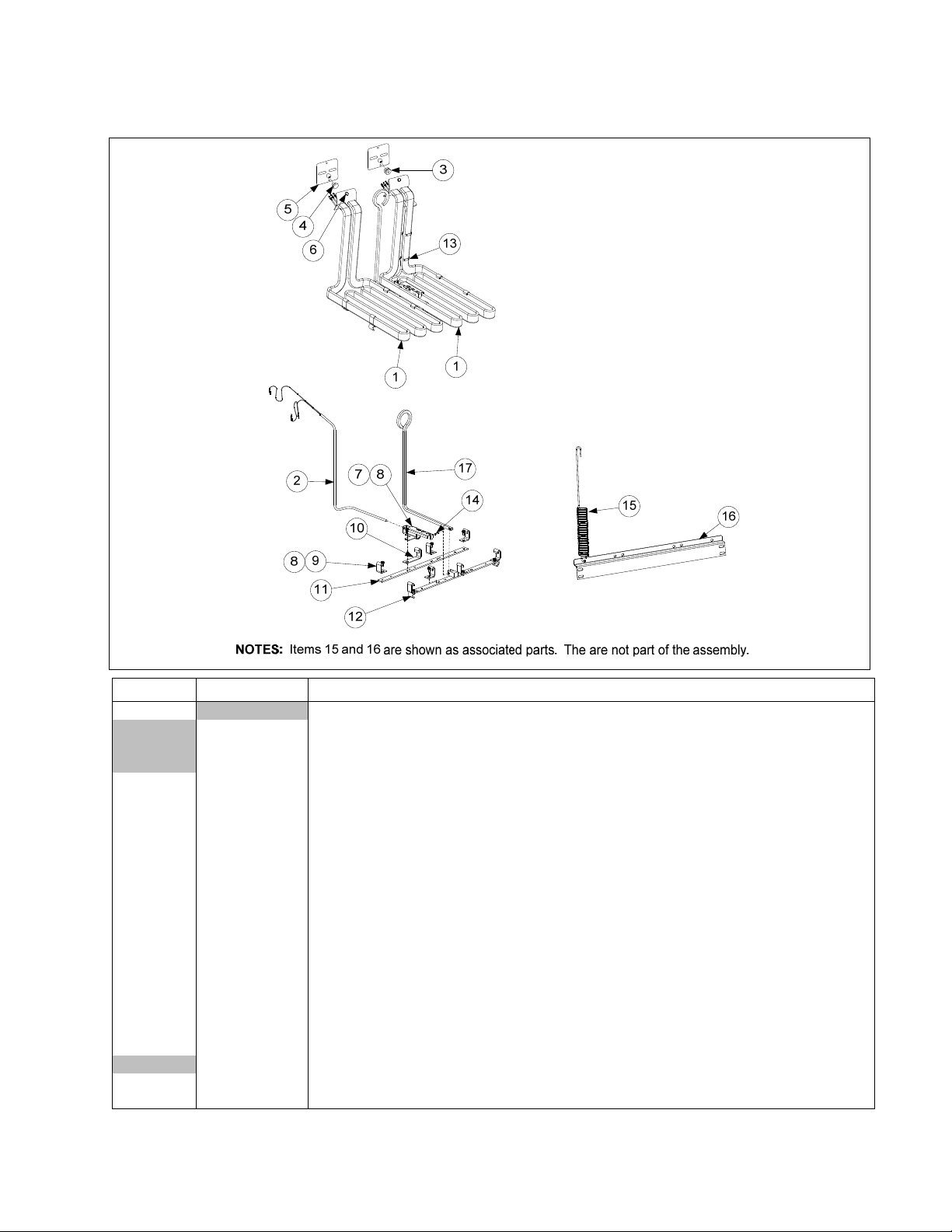
1.9 Basket Lift Assembly and Associated Parts cont.
ITEM PART # COMPONENT
1061808SP Basket Lift Assy, 100-120/480VAC w/Relay (Items 1-20) Assembly not shown
1061805SP Basket Lift Assy, 200-220VAC w/Relay (Items 1-20) Assembly shown
* 1061806SP Basket Lift Assy, 230-250VAC w/Relay (Items 1-20) Assembly not shown
1 8101012 Rod, Basket Lift
2 8130035 Bushing, Bronze
3 8072513 Capacitor, 12.5 μFd 330VAC
4 9018499 Chassis, Left Basket Lift
5 9028499 Chassis, Right Basket Lift
6 8070159 Connector, 12-Pin Female
7 9005529 Gusset, Basket Lift Motor
8 8120442 Insulation, Microswitch
9 8072572 Microswitch
10 8065964SP Motor Assy, 208-240VAC Modular Basket Lift
11 2002942 Mount, Modular Basket Lift
12 8071683 Relay, 12VDC
13 Resistor Assy
8068530SP
1062770SP
* 1062771SP
14 8090082 Ring, Bushing Retainer
15 9104776
16 8090127 Screw, ¼”-20 X ½” Slotted Round Head
17 8237986 Arm, Left Basket Lift
18 8237987 Arm, Right Basket Lift
19 8100179 Button, Plug
20 1082743SP Roller Assy, Basket Lift
21 1082860 Mount, Basket Lift Roller
22 8100194 Roller, Basket Lift
23 8100374 Spacer, Basket Lift Roller
24 8090508 Bolt, ¼”-20 X 1¼ “
25 8237980 Guide, Basket lift Left
26 8238023 Guide, Basket lift Right
27 8090990 Nut, ¼-20 Cap
* 8241477 Tray, Drip Right
* 8241476 Tray, Drip Left
* 1065962 Harness, RE BL Interface (from Basket Lift Assy to control box)
* WIR0166 Wire Assy, 100-250VAC Basket Lift
* Not illustrated
Basket Lift Assemblies (see Note 1 in illustration)
100-120V Modular Basket Lift (see Note 2 in illustration)
208-220VAC Modular Basket Lift (see Note 3 in illustration)
230-250VAC Modular Basket Lift (see Note 3 in illustration)
Cover, Modular Basket Lift Rear S/S (Use 9004776 for Mild Steel)
Wire Assemblies
1-19
Page 23

1.10 Wiring Connectors, Pin Terminals and Power Cords
ITEM PART # COMPONENT
* 8075625 Cordset, 3 Phase, 4 Wire, 113” 4 Gauge, Plug- Hubbell HBL-8462C
* 8075854 Cord, 3 Phase, 4 Wire, 113” 4 Gauge, Plug- None
* 8073836 Cordset, FPP European Power, 5 Wire, 92”, 10 Gauge, Plug- Hubbell C532P6S
* 1060516 Cordset, CE/Export Fryer and Motor with Ring Terminals 220-250V
* 8073835 Cable, Export, 5 Wire, 92”, 10 Gauge, Plug- None
* 8073838 Cable, Export, 5 Wire, 147”, 10 Gauge, Plug- None
* 8074979 Cordset, FPP European Power, 5 Wire, 92”, 10 Gauge, Plug- Mennekes 532P6-14
* 8074143 Cable, Export, 5 Wire, 118”, 10 Gauge, Plug- None
* 8073976 Cable, Export, 5 Wire, 177”, 10 Gauge, Plug- None
* 8073977 Cable, Export China, 5 Wire, 165”, 10 Gauge, Plug- None
* 8074005 Cable, Export Australia, 5 Wire, 104”, 10 Gauge, Plug- None
Connectors and Tools
1 8071068 2-Pin Female
2 8070158 6-Pin Female
3 8070156 9-Pin Female
5 8070159 12-Pin Female
5 8070875 15-Pin Female
6 8071067 2-Pin Male
7 8070157 6-Pin Male
8 8070155 9-Pin Male
9 8070160 12-Pin Male
10 8070804 15-Pin Male
11 8261341 Terminal, Female Split Pin (Pkg of 25)
12 8261342 Terminal, Male Split Pin (Pkg of 25)
13 8072518 Plug, Mate-N-Lock (Dummy Pin)
14 8070928 Extract Tool Pin Pusher
15 8064855 Pin Pusher Screwdriver Assembly
16 2302345 SMT Pin Extractor
* 8074660PK SMT Pin Service Repair Kit
17 1080716 Box, RTI Test
18 8238990 Wrench w/a, 1-1/16" (used with OQS Sensor installation)
19 8238991 Wrench w/a, 1-1/16" Crows Foot (used with OQS Sensor installation)
* Not illustrated
Power Cords
DELTA
WYE
1-20
Page 24

1.11 Fasteners
ITEM PART # COMPONENT
* 8090429 Bolt, ¼-inch – 20 x 2.00-inch Hex Head ZP Tap
* 8090131 Bolt, ¼-inch -20 x ¾-inch Hex
* 8091020 Cap Screw, 5/16-inch-18 5.50” NC Hex (Connects pump to motor.)
* 8090448 Clip, Tinnerman
* 8261366 Nut, 4-40 Keps Hex (Pkg. of 25) (809-0237)
* 8261358 Nut, 6-32 Keps Hex (Pkg. of 25) (809-0049)
* 8090247 Nut, 8-32 Keps Hex
* 8090893 Nut, 8-32 Crown Acorn
* 8261376 Nut, 10-32 Keps Hex (Pkg. of 10) (809-0256)
* 8090766 Nut, 10-32 Keps Hex SS
* 8090581 Nut, ½ NPT Locking
* 8090020 Nut Cap 10-24 NP
* 8261372 Nut Grip ¼-inch ¼-20 Hex NP (Pkg. of 10) (809-0059)
* 8090417 Nut Flange ¼-inch ¼-20 Serr
* 8090535 Nut, "T" ¼-inch-20 x 7/16 SS
* 8090495 Nut, ¼-inch – 20 Press
* 8090540 Nut, Lock ½-inch-13 Hex 2-Way ZP
* 8261359 Screw, 4-40 x ¾-inch Slotted Round Head (Pkg. of 25) (809-0354)
* 8261365
*
* 8090359 Screw, 8 x ¼-inch Hex Washer Head
* 8090360
* 8261371 Screw, 8 x ½-inch Hex Head ZP (Pkg. of 25) (809-0361)
*
*
* 8090104 Screw, 8-32 x ½-inch Slotted Head ZP
* 8261363 Screw, 8-32 x ½-inch NP (Pkg. of 25) (809-0103)
* 8261360 Screw, 10-24 x 5/16-inch Round Slot Head ZP (Pkg. of 25) (809-0024)
*
*
* 8090270 Screw, 10-32 x ½-inch Phillips Head ZP
* 8261375 Screw, 10-32 x ¾-inch Hex Trim Head SS (Pkg. of 5) (809-0401)
* 8091000 Screw, 10-32 x 1¼-inch Hex Sck C/S
* 8261374 Screw, 10 x ½-inch Hex Head (Pkg. of 25) (809-0412)
* 8090266 Screw, 10 x ½-inch Phillips Head ZP
*
*
* 8090123 Screw, 10 x ¾-inch Slot Head
* 8261389 Screw, 1/4-20 x ¾-inch Hex Head ZP (Pkg. of 10) (809-0131)
* 8090582 Washer ½ NPT Locking
* 8090184 Washer, #10 LK ZP
* 8090190 Washer, .625 X .275 X 40 Flat SS
* 8090191 Washer, Lock ¼ Spring ZP
* 8090193 Washer, Flat ¼ Nylon
* 8090194 Washer, Flat 5/16-inch ZP
8090357 Screw, 6 x ⅜-inch Phillips Head NP
8090364 Screw, 8 x ⅝-inch Hex Washer Head ZP
8090518 Screw, 8-32 x ⅜-inch Hex Washer Slotted Head SS
8261330
8091003
8090434 Screw, 10 x ⅜-inch Hex Washer Head NP
8091021 Screw, 10 x ⅜-inch Torx Pan Type B
Screw, 6-32 x ⅜-inch Slot Head (Pkg. of 25) (809-0095)
Screw, 8 x ⅜-inch Hex Washer Slot Head
Screw, 10-32 x ⅜-inch Slot Head SS (Pkg. of 25) (809-0117)
Screw, 10-32 x ⅜-inch Hex Trim Head SS
1-21
Page 25

1.12 Wiring Diagram for Harness Part Numbers
1-22
Page 26

8700LINEAVENUE,SHREVEPORT,LA71106‐6800
FRYMASTER
WWW.FRYMASTER.COM
EMAIL:FRYSERVICE@MTWFS.COM
318‐865‐1711
800‐551‐8633
844‐724‐CARE(2273)
*8197319*
Every new piece of Manitowoc Foodservice equipment comes with KitchenCare™ and you choose the level of service that meets
your operational needs from one restaurant to multiple locations.
– Warranty & lifetime service, certified OEM parts, global parts inventory, performance audited
StarCare
ExtraCare
LifeCare
Talk with KitchenCare™
To learn how Manitowoc Foodservice and its leading brands can equip you, visit our global web site at
www.manitowocfoodservice.com, then discover the regional or local resources available to you.
©2016 Manitowoc Foodservice except where explicitly stated otherwise. All rights reserved. Continuing product improvement may necessitate change of specifications without notice.
Part Number FRY_P_8197319 11/2016
– CareCode, 24/7 Support, online/mobile product information
– Install & equipment orientation, planned maintenance, KitchenConnect™, MenuConnect
- 1-844-724-CARE - www.mtwkitchencare.com
 Loading...