

Page 1
17EC, 17ECS, ESW and EWBS
Installation, Operation, Service & Parts Manual
Electric Cooker Models
Frymaster, a member of the Commercial Food Equipment Service Association, recommends
using CFESA Certified Technicians.
24-Hour Service Hotline 1-800-551-8633
Online manual updated
06/07/04
*8195680*
MAY 2003
Page 2
NOTICE
IF, DURING THE WARRANTY PERIOD, THE CUSTOMER USES A PART FOR THIS ENODIS
EQUIPMENT OTHER THAN AN UNMODIFIED NEW OR RECYCLED PART PURCHASED
DIRECTLY FROM FRYMASTER/DEAN, OR ANY OF ITS AUTHORIZED SERVICE CENTERS,
AND/OR THE PART BEING USED IS MODIFIED FROM ITS ORIGINAL CONFIGURATION, THIS
WARRANTY WILL BE VOID. FURTHER, FRYMASTER/DEAN AND ITS AFFILIATES WILL NOT BE
LIABLE FOR ANY CLAIMS, DAMAGES OR EXPENSES INCURRED BY THE CUSTOMER WHICH
ARISE DIRECTLY OR INDIRECTLY, IN WHOLE OR IN PART, DUE TO THE INSTALLATION OF
ANY MODIFIED PART AND/OR PART RECEIVED FROM AN UNAUTHORIZED SERVICE CENTER.
DANGER
Improper installation, adjustment, alteration, service, or maintenance can cause
property damage, injury, or death. Read the installation, operating, and service
instructions thoroughly before installing or servicing this equipment.
DANGER
For your safety, do not store or use gasoline or other flammable liquids or vapors in the
vicinity of this or any other appliance.
DANGER
This equipment is intended for indoor use only. Do not install or operate this
equipment in outdoor areas.
DANGER
Do not operate this equipment unless it has been properly installed and checked by
qualified personnel.
DANGER
Do not operate this equipment unless all covers and access panels are in place and
properly secured.
DANGER
Do not attempt to repair or replace any component of this equipment unless power to
the unit has been disconnected.
DANGER
If the power supply cord is damaged, it must be replaced by the manufacturer or its
service agent or similarly qualified persons in order to avoid a hazard.
DANGER
Use caution when setting up, operating, or cleaning this equipment to avoid contact
with heated surfaces.
DANGER
Do not use water jets to clean this equipment.
Page 3

ELECTRIC COOKER MODELS 17EC, 17ECS, ESW AND EWBS
TABLE OF CONTENTS
CHAPTER 1: General Information
1.1 Parts Ordering and Service Information 1-1
1.2 Safety Information 1-1
1.3 Equipment Description 1-2
1.4 Installation, Operating, and Service Personnel 1-3
1.5 Definitions 1-3
1.6 Shipping Damage Claim Procedure 1-4
CHAPTER 2: Installation Instructions
2.1 General Installation Requirements 2-1
2.2 Caster/Leg Installation 2-2
2.3 Pre-Connection Preparations 2-2
2.4 Connection to the Electrical Power Supply 2-3
CHAPTER 3: Operating Instructions
3.1 Spaghetti Magic II Controller (As Used on 17EC and 17ECS Units) 3-1
3.2 Computer Magic III Controller (As Used on EWBS Units) 3-3
3.3 Thermostat Control and Switch Panel (As Used on ESW and EWBS Units) 3-8
3.4 Boiling Out the Cookpot 3-9
CHAPTER 4: Preventive Maintenance
Daily Preventive Maintenance 4-1
CHAPTER 5: Operator Troubleshooting
5.1 Introduction 5-1
5.2 Operator Troubleshooting Guide 5-2
5.3 Replacing the Controller (17EC/17ECS and EWBS with CM III Computer) 5-3
5.4 Replacing Fuses in 17EC and 17ECS Models 5-4
CHAPTER 6: 17EC/17ECS Service Procedures & Parts
6.1 Functional Description ................................................................................................... 6-1
6.2 Accessing Equipment for Servicing ............................................................................... 6-2
6.3 Replacing Equipment Components ................................................................................ 6-2
6.3.1 Replacing the Computer................................................................................................. 6-2
6.3.2 Replacing Electronic Components Other than the Computer ........................................ 6-2
6.3.3 Replacing a Heating Element ......................................................................................... 6-3
6.3.4 Replacing the High-Limit Thermostat ........................................................................... 6-5
6.3.5 Replacing a Water-Level Sensor.................................................................................... 6-6
6.3.6 Replacing the Temperature Probe .................................................................................. 6-6
6.3.7 Replacing the Pressure Regulator or Solenoid Valve .................................................... 6-7
6.3.8 Replacing the Water Faucet ........................................................................................... 6-7
6.3.9 Replacing a Basket Lift Motor or Microswitch.............................................................. 6-8
6.3.10 Replacing the Cookpot or Rinse Tank ........................................................................... 6-9
6.4 Technician Troubleshooting......................................................................................... 6-11
i
Page 4

6.4.1 How the Power Supply System Works ........................................................................ 6-11
6.4.2 How the Computer Works............................................................................................ 6-11
6.4.3 How the Autofill/Autoskim System Works ................................................................. 6-12
6.4.4 How the Water Heating System Works ....................................................................... 6-12
6.4.5 How the Basket Lift System Works ............................................................................. 6-13
6.4.6 Technician Troubleshooting Guides ............................................................................ 6-14
Troubleshooting the 24VAC Power Supply System.................................................... 6-14
Troubleshooting the 24VAC Power to Computer........................................................ 6-15
Troubleshooting the Autofill System ........................................................................... 6-16
Troubleshooting the Water Heating System ................................................................ 6-17
Troubleshooting the Basket Lift System ...................................................................... 6-18
6.5 Parts List....................................................................................................................... 6-19
Accessories................................................................................................................... 6-19
Basket Lift Components............................................................................................... 6-20
Cabinetry ...................................................................................................................... 6-22
Cookpot, Rinse Tank, and Drain Components............................................................. 6-24
Electronics .................................................................................................................... 6-26
Water Supply System Components.............................................................................. 6-28
6.6 Wiring Diagram............................................................................................................ 6-29
CHAPTER 7: ESW/EWBS Service Procedures & Parts
7.1 Functional Description ................................................................................................... 7-1
7.2 Accessing Equipment for Servicing ............................................................................... 7-3
7.3 Replacing Equipment Components ................................................................................ 7-3
7.3.1 Replacing the Computer................................................................................................. 7-3
7.3.2 Replacing Electronic Components Other than the Computer ........................................ 7-3
7.3.3 Replacing a Heating Element ......................................................................................... 7-4
7.3.4 Replacing the High-Limit Thermostat ........................................................................... 7-5
7.3.5 Replacing a Water-Level Sensor.................................................................................... 7-6
7.3.6 Replacing the Temperature Probe .................................................................................. 7-6
7.3.7 Replacing the Pressure Regulator or Solenoid Valve .................................................... 7-8
7.3.8 Replacing the Water Faucet ........................................................................................... 7-8
7.3.9 Replacing a Basket Lift Motor or Microswitch.............................................................. 7-9
7.3.10 Replacing the Cookpot ................................................................................................. 7-10
7.4 Technician Troubleshooting......................................................................................... 7-12
7.4.1 How the Power Supply System Works ........................................................................ 7-12
7.4.2 How the Computer Works............................................................................................ 7-12
7.4.3 How the Autofill and Skim Systems Work.................................................................. 7-13
7.4.4 How the Water Heating System Works ....................................................................... 7-13
7.4.5 How the Basket Lift System Works ............................................................................. 7-14
7.4.6 Technician Troubleshooting Guides ............................................................................ 7-15
Troubleshooting the 24VAC Power Supply System.................................................... 7-15
Troubleshooting the Autofill System ........................................................................... 7-16
Troubleshooting the Water Heating System ................................................................ 7-17
Troubleshooting the Basket Lift System ...................................................................... 7-18
7.5 Parts List....................................................................................................................... 7-19
Accessories................................................................................................................... 7-19
Basket Lift Components............................................................................................... 7-20
Cabinetry ...................................................................................................................... 7-22
ii
Page 5

Control Components..................................................................................................... 7-24
Cookpot and Drain Components .................................................................................. 7-25
Electronics .................................................................................................................... 7-26
Water Supply System Components.............................................................................. 7-28
7.6 Wiring Diagrams .......................................................................................................... 7-30
iii
Page 6

THIS PAGE INTENTIONALLY LEFT BLANK.
Page 7

ELECTRIC COOKER MODELS 17EC, 17ECS, ESW AND EWBS
CHAPTER 1: GENERAL INFORMATION
1.1 Parts Ordering and Service Information
In order to assist you as quickly as possible, the Frymaster Factory Authorized Service Center
(FASC) or Service Department representative requires certain information about your equipment.
Most of this information is printed on a data plate affixed to the inside of the door.
Parts orders may be placed directly with your local FASC or distributor. Included with cookers
when shipped from the factory is a list of FASCs. If you do not have access to this list, contact the
Frymaster Technical Service Department at 1-800-551-8633 or 1-318-865-1711.
When ordering parts, the following information is required:
Model Number:
Serial Number:
Voltage:
Item Part Number:
Quantity Needed:
Service information may be obtained by contacting your local FASC/Distributor. Information may
also be obtained by calling the Frymaster Technical Service Department at 1-800-551-8633 or
1-318-865-1711. When requesting service, please have the following information ready:
Model Number:
Serial Number:
Voltage:
In addition to the model number, serial number, and voltage, please be prepared to describe the
nature of the problem and have ready any other information that you think may be helpful in
solving your problem.
RETAIN AND STORE THIS MANUAL IN A SAFE PLACE FOR FUTURE USE.
1.2 Safety Information
Before attempting to operate your unit, read the instructions in this manual thoroughly.
Throughout this manual, you will find safety notations enclosed in boxes similar to the ones
illustrated below and on the following page.
CAUTION
CAUTION boxes contain information about actions or conditions that may cause or result
in malfunction of your equipment.
WARNING
1-1
Page 8

WARNING boxes contain information about actions or conditions that may cause or
result in damage to your equipment, and which may cause your equipment to
malfunction.
DANGER
DANGER boxes contain information about actions or conditions that may cause or result
in injury to personnel, and which may cause damage or malfunctioning of your
equipment
1.3 Equipment Description
The automatic, high-volume Electric Cooker models ESW and EWBS are specifically designed for
rethermalizing pre-cooked packaged foods, boiling seafood, or cooking fresh foods and pasta. All
models are capable of delivering up to 50 pounds (26 kg) of product per hour.
Model Comparison:
17EC/17ECS:
The 17EC and 17ECS series feature two 8.5-kilowatt heating elements in a
16.5 gallon (62.5 liter) stainless steel cookpot. A specially modified SMS II computer
controls the cooking process and the automatic filling (Autofill) and automatic skimming
(Autoskim) features. The Autoskim feature sprays water onto the surface of the water,
forcing starch across to the overflow drain. This eliminates loss of cooking time associated
with removing excess starch buildup. It also keeps the cooking water at the optimum level
by replacing water evaporated during the cooking process. These models are also equipped
with automatic basket lifts. The cookpot is safeguarded against over filling and boilover by
a large overflow drain and a starch diverter. “SD” following the model designation
indicates a stainless steel cookpot and door, and an enameled cabinet. “SC” following the
model designation indicates all stainless steel components. The 17ECS model consists of a
cooker and rinse tank combined in a single cabinet. The 17EC model has no rinse tank.
Both models have a manually operated faucet equipped with a flexible hose.
ESW: The ESW series features a 13-kilowatt cookpot holding 16.5 gallons (62.5 liters) of
water. A rocker-type ON/OFF switch controls electrical power to the unit. A manually
adjusted thermostat regulates water temperature, and a 3-position rocker switch (BOILIDLE-SIMMER) controls power to the heating element. The unit also has two rocker
switches for adding water to the unit. The FAUCET switch opens a normally closed
solenoid valve to add water through a swing-away faucet. The SKIM switch opens a
normally closed solenoid valve to add water through a spray nozzle mounted on the front of
the cookpot. The skim feature sprays water onto the surface of the water, forcing starch to
the overflow drain. This eliminates loss of cooking time associated with removing excess
starch buildup. The cookpot is safeguarded against over filling and boilover by a large
overflow drain. “SD” following the model designation indicates a stainless steel cookpot
and door, and an enameled cabinet. “SC” following the model designation indicates all
stainless steel components.
EWBS: The EWBS series replaced the ESW series. Models feature a 13-kilowatt heating
element in a 16.5-gallon (62.5-liter) cookpot. The control options available include an
operating thermostat and switch panel (identical to that on the ESW, described on the
1-2
Page 9

previous page) or a specially modified CM III computer. The equipment may be configured
as single cooker (E1WBS) or as a battery of two cookers (E2WBS). “SD” following the
model designation indicates a stainless steel cookpot and door, and an enameled cabinet.
“SC” following the model designation indicates all stainless steel components. Optional
features include automatic water filling and a manual skim feature. Standard safety features
on both models include a low-water safety shutoff and a water pressure regulator. All units
may be configured with either a “Sauce Package” consisting of a saucepan insert rack, a
sauce bag rack, and a rack cover, or with a “Pasta Package” consisting of a bulk basket,
portion cups and cup rack, and a strainer board. Both models may be equipped with an
optional swing-away faucet. The cookpot on both models is safeguarded against over filling
and boilover by a large overflow drain and a starch diverter.
1.4 Installation, Operating, and Service Personnel
Operating information for Frymaster equipment is intended for use by qualified and/or authorized
personnel only, as defined in Section 1.5.
All installation and service on Frymaster equipment must be performed by qualified, certified, licensed, and or/authorized installation or service personnel, as defined in Section 1.5.
1.5 Definitions
QUALIFIED AND/OR AUTHORIZED OPERATING PERSONNEL
Qualified/authorized operating personnel are those who have carefully read the information in this
manual and have familiarized themselves with the equipment functions, or who have had previous
experience with the operation of the equipment covered in this manual.
QUALIFIED INSTALLATION PERSONNEL
Qualified installation personnel are individuals, or firms, corporations, or companies that, either in
person or through a representative, are engaged in and are responsible for the installation of
electrical appliances. Qualified personnel must be experienced in such work, be familiar with all
electrical precautions involved, and have complied with all requirements of applicable national and
local codes.
QUALIFIED SERVICE PERSONNEL
Qualified service personnel are those who are familiar with Frymaster equipment and who are
authorized by Frymaster to perform service on Frymaster equipment. All authorized service
personnel are required to maintain a complete set of service and parts manuals and to stock a
prescribed minimum amount of Frymaster parts. Failure to use qualified service personnel will
void the Frymaster Warranty on your equipment. A list of Frymaster Factory Authorized Service
Centers (FASCs) was included with the equipment when it was shipped from the factory.
1.6 Shipping Damage Claim Procedure
Your Frymaster equipment was carefully inspected and packed before leaving the factory. The
transportation company assumes full responsibility for safe delivery upon acceptance of the equipment for transport.
1-3
Page 10

What to do if your equipment arrives damaged:
1. File a claim for damages immediately, regardless of the extent of damages.
2. Inspect for and record all visible loss or damage and ensure that this information is noted on
the freight bill or express receipt and is signed by the person making the delivery.
3. Concealed loss or damage that was unnoticed until the equipment was unpacked should be
recorded and reported to the freight company or carrier immediately upon discovery. A
concealed damage claim must be submitted within 15 days of the date of delivery. Ensure that
the shipping container is retained for inspection.
FRYMASTER DOES NOT ASSUME RESPONSIBILITY
FOR DAMAGE OR LOSS INCURRED IN TRANSIT.
1-4
Page 11

ELECTRIC COOKER MODELS 17EC, 17ECS, ESW AND EWBS
CHAPTER 2: INSTALLATION INSTRUCTIONS
2.1 General Installation Requirements
PROPER INSTALLATION IS ESSENTIAL FOR EFFICIENT, TROUBLE-FREE
OPERATION OF YOUR COOKER. ANY UNAUTHORIZED ALTERATIONS MADE TO
THIS EQUIPMENT WILL VOID THE FRYMASTER WARRANTY.
Upon arrival, inspect the cooker carefully for visible or concealed damage. (See Shipping Damage
Claim Procedure in Chapter 1.)
NATIONAL CODE REQUIREMENTS
This equipment is to be installed in compliance with the Basic Plumbing Code of the Building Officials and Code Administrators International, Inc. (BOCA) and the Food Service Sanitation Manual
of the U.S. Food and Drug Administration.
ELECTRICAL GROUNDING REQUIREMENTS
All electrically operated appliances must be grounded in accordance with all applicable national and
local codes. A wiring diagram is located on the inside of the equipment door. Refer to the rating
plate on the inside of the door for proper voltages.
FCC COMPLIANCE
The user is cautioned that any changes or modifications to Frymaster computers not expressly approved by the party responsible for compliance could void the user’s authority to operate the equipment. Frymaster computers have been tested and found to comply with the limits for a Class A
digital device, pursuant to Part 15 of the FCC rules. While these devices are verified as Class A devices, they have been shown to meet the Class B limits. These limits are designed to provide reasonable protection against harmful interference when the equipment is operated in a commercial environment. This equipment generates, uses, and can radiate radio frequency energy and, if not installed and used in accordance with the instruction manual, may cause harmful interference to radio
communications. Operation of the equipment in a residential area is likely to cause harmful interference in which case the user will be required to correct the interference at his own expense.
If necessary, the user should consult the dealer or an experienced radio and television technician for
additional suggestions.
The user may find the booklet “How to Identify and Resolve Radio-TV Interference Problems”
helpful. It is prepared by the Federal Communications Commission and is available from the U.S.
Government Printing Office, Washington, DC 20402, Stock No. 004-000-00345-4.
2-1
Page 12
2.2 Caster/Leg Installation
Depending upon the specific configuration ordered, your unit might have been shipped without installed casters or legs. If casters or legs are installed, you may skip this section and proceed to Section 2.3, Pre-Connection Preparations.
If your unit requires the installation of casters/legs, install them in accordance with the instructions included in your accessory package.
2.3 Pre-Connection Preparations
After the unit has been positioned in the area where it will be used, ensure the following have been
accomplished before connecting the unit to the electrical power source:
1. This equipment must be stabilized by installing restraining chains on units equipped with
casters or anchor straps on units equipped with legs. Follow the instructions shipped with
the casters/legs to properly install the chains or straps.
2. Level units equipped with legs by screwing the legs out approximately 1 inch, then adjusting
them so that the unit is level.
For units equipped with casters, there are no built-in leveling devices. The floor where the
unit is to be installed must be level.
3. Install the basket lift arms (on units so equipped) on the lift rods (located at the top rear of
the cabinet) so that the basket lift rollers guides the lift arms.
NOTE: Some adjustment of the rollers may be necessary for free movement of the basket lift
arms.
4. If so equipped, connect the water hose(s) to the fitting(s) at the rear of the unit and connect
the unit to the water supply.
CAUTION
Incoming water pressure for all units should be approximately 40 PSI (28.15 kg/cm2).
DANGER
The maximum allowable incoming water pressure for all units is 80 PSI (56.3 kg/cm2).
The maximum allowable incoming water temperature for all units is 180ºF (82ºC).
WARNING
To prevent back flushing, the connection piping should be installed with a vacuum breaker
or means of providing an air gap 1” (2.54 cm) above the cookpot rim.
NOTE: On units equipped with water hoses, the hoses come with a quick-disconnect cou-
pling. The quick disconnect may be attached to the unit or to the water supply line, or it may
be left off entirely, whichever you prefer. If the unit is to be moved frequently (for cleaning
or preventive maintenance), Frymaster recommends installing flexible water lines. If the
cooker is hard-plumbed then moved, the connections may loosen and eventually cause leaks.
2-2
Page 13
Whichever option is chosen, Teflon thread-seal tape, Loctite™ PST56765 or equivalent
thread sealer must be used when installing the fittings.
NOTE: Depending on specific model ordered, either hot or cold water, or both, may be
connected to the unit. If available, connecting hot water will minimize the time required to
bring the unit to a boil when filling with fresh water.
NOTE: In order for the water level sensors to work properly, a certain amount of mineral
content in necessary in the water. For that reason, purified, deionized, or highly filtered
water should not be used.
5. Connect the desired drain plumbing to the drain valve.
2.4 Connecting to the Electrical Supply
DANGER
This unit must be connected to the voltage and phase specified on the rating and serial
number plate located on the inside of the equipment door. To determine the appropriate
wire size, refer to the POWER REQUIREMENTS chart at the bottom of this page.
1. If the unit is not equipped with an installed power cord, open the door and remove the contactor
box cover. Position the unit to gain access to the rear and remove the lower back panel.
2. Insert an appropriately rated power cord into the rear of the contactor box and make connections
in accordance with the applicable wiring diagram on the following page. Install a strain relief on
the power cord and replace the lower back panel and contactor box cover.
3. Attach a plug that complies with national and/or applicable local codes to the free end of the
electrical power cord and plug the unit into an appropriate outlet.
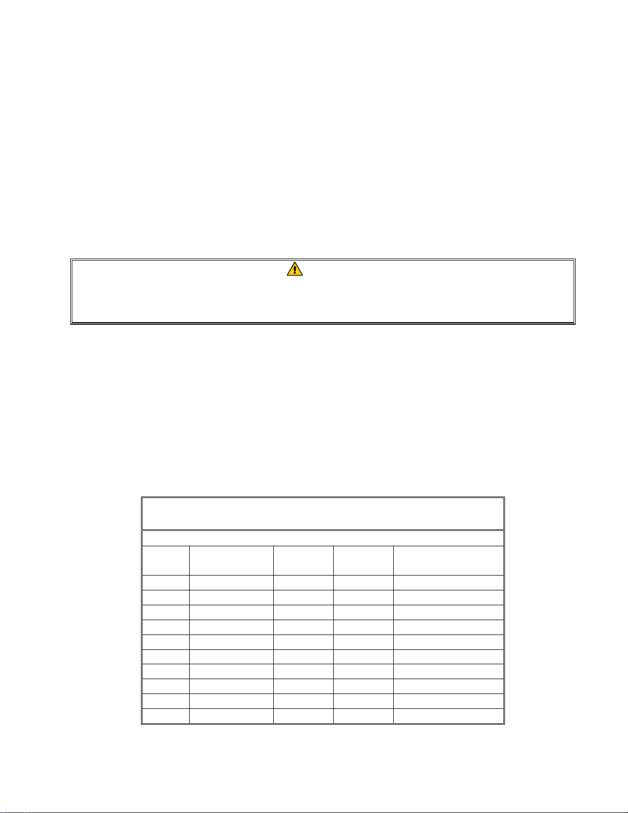
POWER REQUIREMENTS
Use copper wire ONLY, suitable for at least 170ºF (75ºC)
ELECTRIC COOKER MODELS 17EC, 17ECS, ESW, & EWBS
Amps
Volts Phase Watts
200 Single 7860 40 AWG 6 (4.1 mm)
200 Single 12000 60 AWG 4 (5.2 mm)
208 Single 8500 41 AWG 6 (4.1 mm)
208 Single 13000 63 AWG 4 (5.2 mm)
208 3P – Delta 8500 48 AWG 8 (3.3 mm)
200 3P – Delta 12000 35 AWG 6 (4.1 mm)
208 3P – Delta 13000 37 AWG 6 (4.1 mm)
230 3P – Delta 13000 33 AWG 6 (4.1 mm)
200 3P – Wye 12000 21 AWG 8 (3.3 mm)
230 3P – Wye 13000 19 AWG 8 (3.3 mm)
(per leg)
Minimum
Wire Size
2-3
Page 14
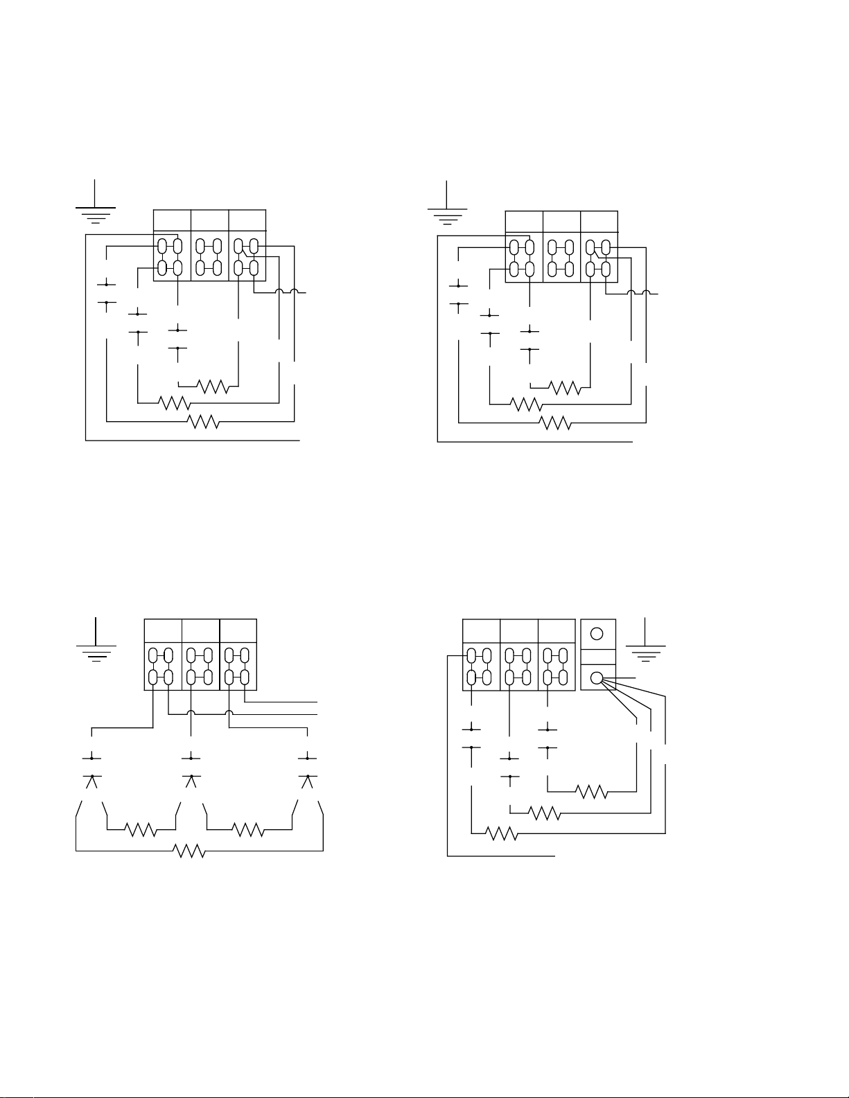
FIELD CONNECTION WIRING DIAGRAMS
1HV
1C1
1
SINGLE PHASE
FIELD CONNECTION
L1
2HV
3HV
1C2
1C3
2
3
L2 L3
4
NEUTRAL TO L3
FROM TRANSFORMER
5
6
FROM TRANSFORMER
SINGLE PHASE (NO NEUTRAL)
FIELD CONNECTION
L1
1HV
1C1
2HV
3HV
1C2
1
1C3
2
3
L2 L3
FROM
TRANSFORMER
4
5
6
FROM TRANSFORMER
1HV
1C1
12
3 PHASE 3 WIRE (DELTA)
FIELD CONNECTION
L2 L3
L1
2HV
1C2
53
FROM TRANSFORMER
FROM TRANSFORMER
3HV
1C3
46
3 PHASE 4 WIRE (WYE)
FIELD CONNECTION
L2 L3
L1
1HV
1C1
2HV
1C2
1
2
N
3HV
1C3
3
FROM TRANSFORMER
FROM TRANSFORMER
4
5
6
2-4
Page 15
ELECTRIC COOKER MODELS 17EC, 17ECS, ESW AND EWBS
CHAPTER 3: OPERATING INSTRUCTIONS
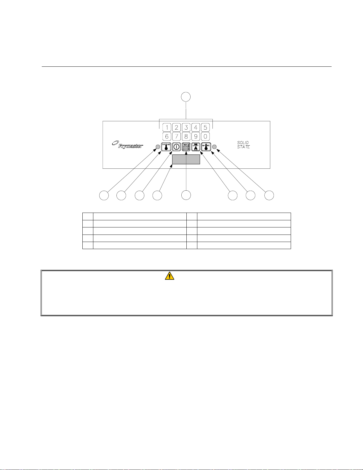
3.1 Spaghetti Magic III Controller (As Used on 17EC and 17ECS Units)
1
5432 7
1 Numeric Keypad 6 Skim Switch (w/Autoskim only)
2 Boil Mode Indicator 7 Timer Start Switch
3 Boil Mode Switch 8 Simmer Mode Switch
4 Power Switch 9 Simmer Mode Indicator
5 LED Display
6
8 9
3.1.1 Introduction
CAUTION
The Spaghetti Magic III (SMS III) computer used in 17EC/17ECS units is specially
configured for them. The programming and operation of the 17EC/17ECS SMS III
computer are different than those of the SMS III computers used in other products.
The computers are not interchangeable.
The Spaghetti Magic III computer allows the operator to specify a specific cook time in minutes and
seconds, then initiate a cooking cycle. The computer is configured for both automatic filling
(AutoFill) and automatic skimming (Autoskim) features.
The BOIL mode is used when actually cooking pasta.
The SIMMER mode feature maintains the water temperature just below boiling (approximately
195ºF/90.6ºC), which conserves energy and water. This feature is designed for rethermalizing
previously cooked packaged products, and for keeping the cooker in standby.
The SKIM feature, when selected, adds water for approximately 3 seconds once a minute. It causes
the water to overflow into the drain, carrying floating starch with it. (A buildup of starch reduces the
efficiency of the cooker and can cause erroneous temperature and water level sensing.)
3-1
Page 16
LOW WATER SENSING automatically de-energizes the heating element if the water in the
cookpot drops too low. When the water level in the cookpot is below the sensor probes, such as
when draining and cleaning the cookpot, the controller display will read LO.
NORMAL WATER LEVEL SENSING, on units configured with the AutoFill feature,
automatically adds water during or after a cooking cycle if the water level is low. With this
automatic filling feature, the water level does not have to be continuously monitored. The cookpot
always has the correct amount of water.
3.1.2 Operating Instructions
CAUTION
If this is the first time the unit is being used after installation, refer to Section 3.4, Boil Out
Procedure.
Before turning the cooker on, ensure that:
• the unit is connected to the water supply.
• the water supply is turned on.
• the unit is plugged into an appropriate outlet.
• the electrical power supply is turned on.
1. Turn the controller on by pressing the Power switch.
2. The unit will automatically enter the simmer mode and the simmer mode indicator will
illuminate. This will bring the cooker to “stand-by” temperature. To enter the boil mode, press
the Boil Mode switch.
3. Enter the desired cooking time using the numeric keypad. The time entered appears in the LED
display.
4. When ready to initiate a cooking cycle, press the Start Timer
switch. The basket lift will automatically lower the basket or portion cups into the cookpot
and the LED display will begin to count down. Simultaneously, the water will be raised to the
boiling point. At the end of the cooking cycle, an alarm will sound briefly to alert you and the
basket lift will automatically raise the basket or portion cups out of the water.
5. The display will automatically return to the previously set cooking time and the unit will return
to the simmer mode. If the same time is desired for the next batch, simply repeat Step 4. If a
different cooking time is desired, follow Steps 3 and 4.
switch then press the Boil Mode
6. To initiate the automatic skimming (Autoskim) feature, press the Skim
3.1.3 Setting the Controller Transition Temperature/Boil Intensity
You may adjust the cooker’s Transition Temperature/Boil Intensity to prevent boilover on
controllers configured with this feature.
3-2
switch.
Page 17

When the water is at or above the minimum temperature for boiling (transition temperature), the
controller pulses power to the elements at a programmable rate. The range can be set between 0 and
9. The default setting is 5. When the water temperature is below boiling point, the power
application is 100 percent.
To set the Transition Temperature/Boil Intensity:
1. Verify that the controller is OFF (the display is blank).
2. Press the Simmer (right thermometer icon) switch to enter the programming mode; CODE appears
in the display.
3. Enter code 1111 (press the 1 button four times). Transition Temperature appears in the display.
(NOTE: If transition temperature does not appear, your controller is not configured with this
feature. Press the Simmer switch to exit the programming mode. The display will go blank.)
4. Enter the minimum temperature for boiling with the keypad. This temperature will vary with
your altitude. As a guide, the table below provides boiling points for altitudes from sea level to
6000 feet (1830 meters).
Altitude Boiling Point
Feet Meters °F °C
0 0 212 100
1000 305 210 99
2000 610 208 98
3000 915 207 97
4000 1220 205 96
5000 1525 203 95
6000 1830 201 94
5. Press the simmer switch; 5BI (the default setting for boil intensity) appears.
6. Use the keypad to enter one of the settings from the table below.
Setting Power ON Power OFF
0 100% 0%
9 90% 10%
8 80% 20%
7 70% 30%
6 60% 40%
5 50% 50%
4 40% 60%
3 30% 70%
2 20% 80%
1 10% 90%
7. Press the simmer switch to lock in the new settings and exit the programming mode. The display
will go blank.
3-3
Page 18

3.1.4 Controller Simmer Mode Adjustment
NOTE: The SMS III Controller simmer temperature is adjustable from 185ºF to 215ºF (85° to
102°C). There are two versions of this controller; one is adjusted by programming, the other is
manually adjusted.
To determine which version of the controller you have, turn the controller off by pressing the
ON/OFF switch. The display will go blank. Press the Simmer (right thermometer icon) switch. If
Code appears in the display, the simmer mode setpoint is changed via programming; if not, skip to
Manual Adjustment below.
1. Press 1, 6, 5, 0 to enter the programming mode. The currently programmed simmer setpoint will
be displayed. If the setpoint is not correct, enter the desired setpoint (for example, press 2, 0, 0
to program the simmer setpoint to 200º.
2. Press the Simmer switch again to lock in the setpoint, then press the ON/OFF switch to turn the
controller on and return to the normal operating mode.
Manual Adjustment
1. With the unit in the simmer mode, place the tip of a good grade thermometer near the
temperature probe and determine the actual water temperature in degrees Fahrenheit. If the
temperature is within 5ºF (2°C) of the desired simmer temperature, nothing more needs to be
done. If it is not within 5ºF (2°C) of the desired temperature, perform Steps 2 through 5.
2. With the unit in the simmer mode, open the control panel by removing the screws in the upper
corners and tilting the panel out.
3. Remove the black rubber plug from the top of the controller housing.
4. Using a small, flat-tipped screwdriver, turn the adjusting screw to change the simmer setpoint.
¼ turn will change the setpoint about 10ºF (5°C). (You will have to experiment with the
direction of rotation to determine which way to turn to raise or lower the temperature.) Wait at
least 5 minutes, then recheck actual water temperature. Repeat this step until the water
temperature is within 5ºF (2°C) of desired temperature.
5. Replace the plug in the controller, close the control panel, and replace the screws removed in
Step 1.
3.1.5 Toggling Between Fahrenheit and Celsius Temperature Display
1. There are two versions of the SMS Controller: one that can be toggled between Fahrenheit and
Celsius temperature display and one that cannot. To determine which version you have, turn the
controller off by pressing the Power switch. The display will go blank. Press the Simmer
switch. If Code appears in this display, the temperature display can be changed. If not, the
display cannot be changed.
2. If Code appears in the display, press 1, 6, 5, 8. The display will toggle from Fahrenheit to
Celsius, or from Celsius to Fahrenheit.
3-4
Page 19
Press the Boil Mode switch to display the cookpot temperature. If an F follows the
temperature, the display is in Fahrenheit; if a C follows the temperature, the display is in Celsius.
3.1.6 Shutting the 17EC/17ECS Down
Turn the unit off by pressing the Power
switch. If shutting down at the end of the day, drain and
clean the cookpot, and put the cookpot cover in place.
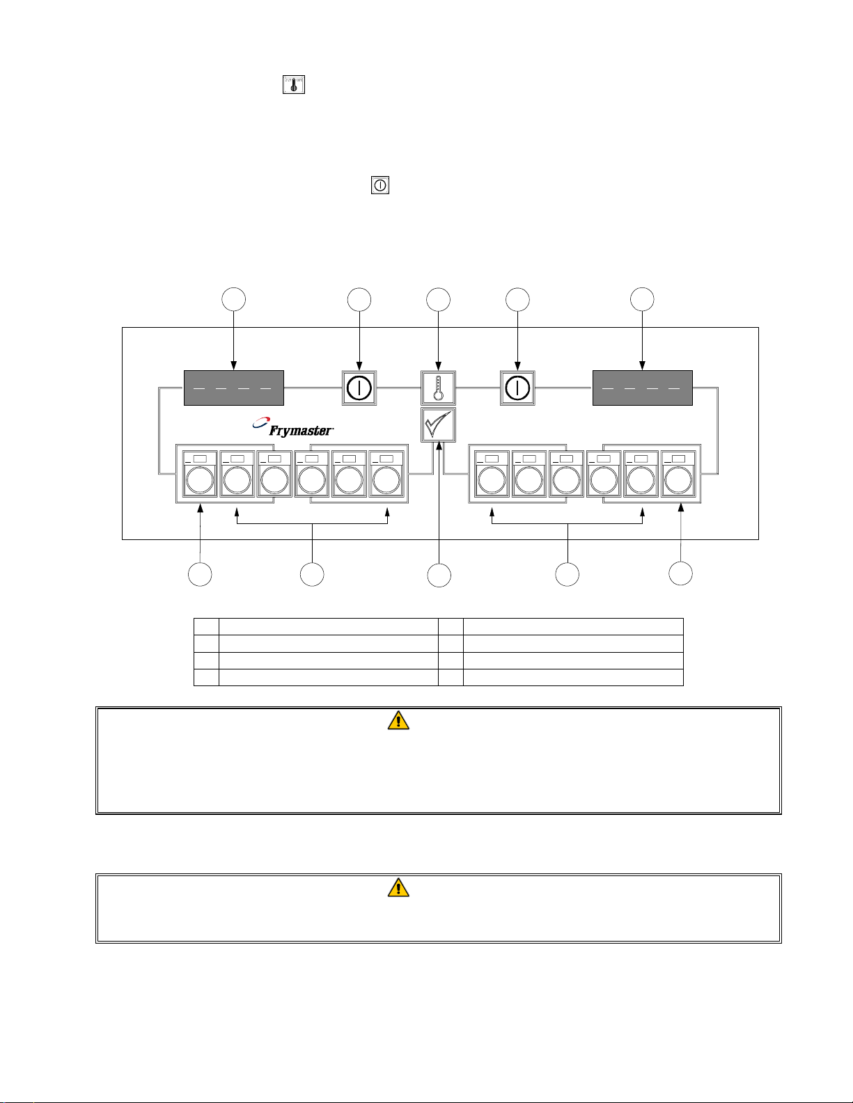
3.2 Computer Magic III Controller (As Used on EWBS Units)
L 1
5
1
2
3 4 5 6 7
6 7
2 3 2
4
COMPUTER MAGIC
8
9 0
1
R
8
1 LED Displays 5 Boil Mode Switch
2 Power Switches 6 Product Buttons 1 through 5
3 Temperature Check/Program Lock 7 Product Buttons 6 through 10
4 Program Mode Switch 8 Simmer Mode Switch
CAUTION
The Computer Magic III (CM III) computer used in Electric Water Bath Systems is specially
configured for them. The programming and operation of the EWBS CM III are different
than those of the CM III computers used in electric fryers.
The two computers are not interchangeable.
3.2.1 Start-Up Procedure
CAUTION
If this is the first time the unit is being used after installation, refer to Section 3.4, Boil Out
Procedure.
3-5
Page 20
SETTING THE UNIT UP FOR FIRST-TIME OPERATION
Before turning the cooker on, ensure that:
• the unit is connected to the water supply.
• the water supply is turned on.
• the unit is plugged into an appropriate outlet.
• the electrical power supply is turned on.
CAUTION
It is recommended that the simmer setpoint and the cook/stir times for all 10 products be
programmed before the unit is first used in a cooking cycle.
When the unit is tested at the factory, the simmer setpoint and product cook times are programmed.
These test settings are not default settings. You must program the unit for your own particular
products. Program the setpoint and all 10 product cook/stir times as follows:
1. Turn the computer on by pressing the Power Switch.
2. Enter the programming mode by pressing the Program Mode Switch . CodE appears in
the left display. If you enter the programming mode by mistake, press the switch again to
exit the programming mode.
NOTE: If you try to enter the programming mode while the computer is cooking, the display
will flash BUSY.
NOTE: The unit comes from the factory configured to display in degrees Fahrenheit. To
toggle back and forth between Fahrenheit and Celsius, press the Program Mode switch,
then enter the code
the Temperature Check/Program Lock switch to lock in the new display option.
3. Enter the number 1 6 5 0 by pressing the corresponding product buttons. Unless this
code is entered, programming will not be accepted. This is to prevent unauthorized changes
to your current instructions.
4. SP-r (Setpoint) will appear in the left LED display. Any previously programmed
temperature setpoint will appear in the right display. To change the setpoint, enter the
desired setpoint temperature using the corresponding product buttons. The setpoint can be
programmed for any value up to 212°F (100°C). Press the Program Mode
in the new setpoint (or the old setpoint, if it was not changed).
1 6 5 8
by pressing the corresponding product buttons. Next, press
switch to lock
5. SELP (Select Product) will appear in the left display. Press the product button to be
programmed (or press to return to the normal operating mode).
6. COOC (Cook Time) will now show in the left display. Any previously programmed
cooking time will appear in the right display. Pressing
time. To change the cooking time, enter the new time using the product buttons. The cook
time can be programmed up to 59:59. Press
to lock in the new time.
3-6
will accept the current cooking
Page 21
NOTE: The computer can be programmed for either “standard” or “slow” clock speed.
The standard clock displays minutes and seconds, the slow clock displays hours and minutes.
To toggle back and forth between clock speeds, press the Program Mode switch, then
enter the code 1 6 5 3 using the product buttons.
To determine if the clock speed is set to standard or slow, initiate a cook cycle by
pressing a product button. If the computer is set to the standard clock, the time in the
LED display will immediately begin to count down. If it does not, the computer is set to
the slow clock.
7. Sh1 (Stir Time 1) appears in the left display. If your product requires stirring during the
cooking process, set the number of seconds to cook before stirring using the product buttons.
If your product does not require stirring, enter “0”. The number entered will appear in the
right display. The stir time can be programmed up to 59:59, but cannot exceed the product
cook time. Press to lock in the programmed time.
Sh2 will appear. Program the time of the second stir time as above. Be sure the time
entered is greater than Sh1 or else is “0”.
Sh3 will appear. Program the length of the third stir time in the same manner as for Stir
Times 1 and 2. Be sure that the time entered is greater than Sh2 or else is “0”.
For example, entering “30” means the product needs to be stirred after it has been cooking
for thirty seconds. At the end of thirty seconds, an alarm will sound and the product switch
will flash until cancelled by the operator pressing the product button.
CAUTION
Remember: Sh2 must be greater than Sh1 (or else be “0”). Sh3 must be greater than
Sh2 (or else be “0”). None of the stir times can be greater than the cook time entered in
Step 6.
8. SELP (Select Product) will again appear in the left display. If more products are to be
programmed, follow Steps 5 through 8 for each additional product.
9. When you complete your programming, lock in the whole program by pressing the
Temperature Check/Program Lock Switch .
3.2.2 Operating the Computer
Turn the computer on by pressing the Power
in either LED Display indicates the unit is heating.
1. One of the following will normally be displayed:
switch. NOTE: A decimal between digits 1 and 2
a. °-Lo, indicating that the water temperature is 11°F (6°C) lower than the setpoint.
b. “- - - -” indicating that the water temperature is in the cooking range. NOTE: For best
results, cooking should not be attempted unless the display indicates “- - - -”.
3-7
Page 22
NOTE: You may also see one of these indicators of abnormal operation:
¾ °-Hi, indicating that the water temperature is 11°F (6°C) higher than the setpoint
¾ HELP, indicating a heating problem.
¾ Prob, indicating that the computer temperature probe circuit is open.
2. Press a product button to start a cook cycle.
a. The programmed cook time will appear and the countdown begins.
b. If stir times are programmed, the operator will be notified to agitate the product a
predetermined number of seconds after the cook cycle has begun. An alarm will sound, the
display will read S t i r, and the LED in the product button will blink. To cancel the alarm,
press the indicated product button.
If no stir times have been programmed, S t i r will not appear during the cook cycle.
CAUTION
Pressing the product button twice while the Sh alarm sounds will cancel the cook cycle as
well as the alarm.
c. At the end of the cook cycle, an alarm will sound, COOC will be displayed, and the
associated product button will flash. To cancel the alarm, press the flashing button.
3. To check the frypot temperature at any time, press the Temperature Check switch once. To
check the setpoint, press the switch twice. If you suspect the temperature probe is defective,
check the temperature of the cookpot with a thermometer or pyrometer to verify that the
computer readout is reasonably close to the measured reading.
4. During idle periods when the cooker is on but not in use, “- - - -” should appear in both displays,
indicating that the cookpot is at setpoint. If not, check the actual temperature and setpoint.
SELECTING FAHRENHEIT– CELSIUS DISPLAY MODE
1. The computer can display temperatures in either Fahrenheit or Celsius. To change from one to
the other, press the Program Mode Switch . CodE will appear in the left display.
2. Enter the code number 1 6 5 8 on the number keypad. The computer will toggle the
temperature display from Celsius to Fahrenheit or from Fahrenheit to Celsius.
3. Press the Temperature Check/Program Lock Switch to display the temperature in the newly
selected mode.
SELECTING STANDARD OR SLOW CLOCK
3-8
Page 23
The computer can be programmed for either “standard” or “slow” clock times. The standard clock
displays minutes and seconds, the slow clock displays hours and minutes.
To toggle back and forth between times press the Program Mode switch, then enter the code
1 6 5 3 using the product buttons.
SELECTING BOIL OR SIMMER MODE
In the SIMMER mode, the water temperature is maintained at the setpoint programmed by the
operator. In the BOIL mode, the water temperature is raised to 212°F (100°C).
Select the SIMMER mode by pressing the R button. If the temperature of the water is above the
setpoint, °-hi will be displayed. If the temperature of the water is below the setpoint, °-lo will be
displayed. If the temperature is within 11°F (6°C) of the setpoint, “- - - -” will be displayed.
The BOIL mode is selected by pressing the L button. The display will show
boil
and the
temperature of the water will be raised to 212°F (100°C).
3.2.3 Shutting the EWBS with CM III Computer Down
Turn the unit off by pressing the Power switch.
If shutting down at the end of the day, drain and clean the cookpot, and put the cookpot cover in
place.
CAUTION
The electronic circuitry in your computer can be affected adversely by power fluctuations
and electrical storms. If it fails to function or program properly for no apparent reason, try
unplugging the computer from the interface board and plugging it back in. This could
prevent a service call.
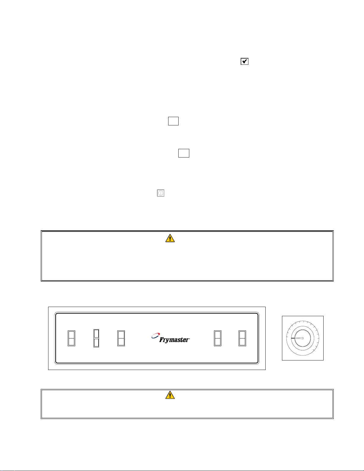
3.3 Thermostat Control and Switch Panel (Used on ESW and EWBS Units)
1
5
8
7
5
1
1
ON
OFF
POWER
POWER
TROUBLE
BOIL
IDLE
SIMMER
HEAT CYCLE
ON
OFF
FAUCET SKIM
ON
OFF
165
5
5
1
9
5
2
0
5
2
1
5
2
2
5
THERMOSTAT CONTROL
SWITCH PANEL
CAUTION
If this is the first time the unit is being used after installation, refer to Section 3.4, Boil Out
Procedure.
3-9
Page 24

On ESW units and EWBS units without CM III computers, a thermostat located inside the door
maintains the simmer mode temperature. Rocker switches on the control panel turn the power on
and off, control the heat cycle, and add water.
When the Power switch is placed in the ON position, the white power indicator will illuminate. If
the unit is equipped with the AutoFill feature and the water level in the cookpot is below the upper
water level sensor, the cookpot will immediately begin to fill with water. If the Heat Cycle switch is
in the ON or SIMMER position, the heating element will energize as soon as the lower water level
sensor is covered with water. Illumination of the red trouble light at anytime indicates that the highlimit safety has tripped. If the red trouble light illuminates, place the Power switch in the OFF
position immediately.
When the Heat Cycle switch is placed in the IDLE position, the heating element is de-energized, but
power to the Faucet and Skim switches is maintained. Placing this switch in the SIMMER position
maintains the water at the temperature indicated on the thermostat control dial. The switch is placed
in the BOIL position for cooking product or reheating packaged sauces. A built in low-water safety
feature prevents the heating element from being energized unless the lower water level sensor is
covered with water, regardless of the position in which the switch is placed.
On units with the AutoFill feature, placing the Power switch to the ON position activates the feature,
causing the water solenoid valve to open, adding water to the cookpot until the water level reaches
the upper water level sensor. When the water reaches the upper sensor, the valve closes. As long as
the switch is in the ON position, whenever the water level drops below the upper water level sensor,
water will be automatically added to the cookpot. If the switch is placed in the OFF position, the
AutoFill feature is disabled. On units without AutoFill, the cookpot must be manually filled by
placing the faucet switch in the ON position. The switch must be placed in the OFF position to stop
the water flow.
The Skim switch allows the operator to add water to the cookpot during the cooking cycle. This
causes any accumulation of starch floating on the surface of the water to be washed down the
overflow drain. Water will be added as long as the switch is in the ON position.
Turn the unit off by placing the Heat Cycle switch in the IDLE position and the Power switch in the
OFF position. If shutting down at the end of the day, drain and clean the cookpot, and put the
cookpot covers in place.
3.4 Boiling Out the Cookpot
The cookpot must be boiled out before first use.
1. Close the drain valve and fill the cookpot with a mixture of cold water and 1 cup of detergent.
2. Place the unit into operation. (See Section 3.1.2 for 8SMS, 8BC or 8C units. See Section 3.2.2
for EWBS units.)
3. Press the simmer switch,
solution to simmer for at least 1 hour.
on 8SMS, 8BC and 8C units or R
on EWBS units, and allow the
3-10
Page 25

4. After the solution simmers for 1 hour, turn the unit off and add cold water until the solution is
cool. Drain the solution and clean the frypot thoroughly. Rinse the cookpot at least twice by
filling with clean water and draining. Dry the cookpot thoroughly with a clean, dry towel.
3-11
Page 26

THIS PAGE INTENTIONALLY LEFT BLANK.
Page 27

ELECTRIC COOKER MODELS 17EC, 17ECS, ESW AND EWBS
CHAPTER 4: PREVENTIVE MAINTENANCE
Daily Preventive Maintenance
It is normal for a coating of starch to form on the elements, sensors, and temperature probes during
operation. If the coating is allowed to build-up, it will adversely affect the operation of the
equipment. The preventive maintenance routines below should be performed at least daily to keep
your equipment functioning at peak efficiency.
Inspect Equipment and Accessories for Damage
Look for loose or frayed wires and cords, leaks, foreign material in cookpot or inside cabinet,
and any other indications that the equipment and accessories are not ready for safe operation.
Clean Cabinet Inside and Out
Clean inside the cabinet with a dry, clean cloth. Wipe all accessible metal surfaces and
components to remove accumulations of oil, dust, or cooking residue.
Clean the outside of the cabinet with a clean cloth dampened with dishwashing detergent,
removing oil, dust, or cooking residue.
DANGER
Never attempt to clean this equipment during the cooking process or when the
cookpot is filled with hot water and/or food products.
Clean Water-Level Sensors, Temperature Sensor, Element, and Cookpot
Turn the equipment off and drain the cookpot.
Clean the water level sensors (located in the front of the cookpot behind the sensor cover).
Normally, a bottlebrush and a solution of detergent and water may be used to clean the sensors
with the cover installed. If the sensors become coated with an unusually heavy layer of starch
or lime, the cover may be removed to better access the sensors for cleaning using a Scotchbrite™ or similar abrasive pad and a solution of detergent and water.
Using a Scotchbrite™ or similar abrasive pad and a solution of detergent and water, clean the
inside of the cookpot. Pay particular attention to the heating element.
Rinse the cookpot thoroughly with clean water at least twice.
4-1
Page 28

THIS PAGE INTENTIONALLY LEFT BLANK.
Page 29

ELECTRIC COOKER MODELS 17EC, 17ECS, ESW AND EWBS
CHAPTER 5: OPERATOR TROUBLESHOOTING
5.1 Introduction
This chapter provides an easy reference guide to the more common problems that may occur during
the operation of this equipment. The troubleshooting guides in this chapter are intended to help you
correct, or at least accurately diagnose, problems with the equipment. Although the chapter covers
the most common problems reported, you may very well encounter a problem not covered. In such
instances, the Frymaster Technical Service Department will make every effort to help you identify
and resolve the problem.
When troubleshooting a problem, always use a process of elimination starting with the simplest
solution and working through to the most complex. Never overlook the obvious. Anyone can forget
to plug a cord into a receptacle or open the valve on the water supply line. Don’t assume that you
are exempt from such occurrences. Most importantly, try to establish a clear idea of why a problem
has occurred. Part of your corrective action involves taking steps to ensure that it doesn’t happen
again. Keep in mind that failure of a small component may often be indicative of potential failure or
incorrect functioning of a more important component or system.
Some of the troubleshooting actions recommended in this chapter involve removing suspect
controllers and substituting controllers that are known to be good, if they are available. Whenever
this is indicated, refer to Section 5.3. Refer to Section 5.4 for instructions on replacing fuses in
17EC and 17ECS models.
If the troubleshooting and corrective actions in this chapter do not solve the problem, the problem is
probably beyond the scope of most operators to solve and you should call your FASC for assistance.
If you have doubts as to the proper action to take, do not hesitate to call the Frymaster Technical
Service Department or your local Frymaster Factory Authorized Service Center for assistance.
Before calling a servicer or the Frymaster HOTLINE (1-800-551-8633):
• Verify that electrical cords are plugged in and that circuit breakers are on.
• Verify that water supply valves are open and that drain valves are fully closed.
DANGER
Hot water can cause severe burns. Never attempt to move a cooker containing hot
water or to transfer hot water from one container to another.
DANGER
Use extreme care when performing electrical circuit tests. Live circuits will be
exposed.
WARNING
Inspection, testing, and repair of electrical components should be performed only by
qualified service personnel. The equipment should be unplugged when servicing,
except when electrical tests are required.
5-1
Page 30

5.2 Operator Troubleshooting Guide
PROBLEM PROBABLE CAUSES CORRECTIVE ACTION
A. No power to unit. A. Turn on circuit breaker.
B. Master Power switch in
Controller does not
activate.
Autofill does not add
water.
Autofill does not shut
off when the cookpot
is full.
Water will not heat
(controller is on, water
is at normal level, but
LO is not showing on
the controller).
Water will not heat
(water above lower
water level sensor and
LO is showing on the
controller).
Water heats but does
not boil.
Water boils in simmer
mode.
Water temperature is
too low in simmer
mode.
Timer does not count
down.
OFF position (17EC and
17ECS models only).
C. Controller not turned on. C. Push power switch.
D. Blown fuse (17EC and
17ECS models only).
A. Water not turned on. A. Turn water on.
B. Defective controller. B. Replace controller (see Section
A. Dirty upper water level
sensor.
B. Insufficient mineral
content in water.
C. Defective controller. C. Replace controller (see Section
A. Dirty low water level
sensor.
B. Insufficient mineral
content in water.
C. Defective controller. C. Replace controller (see Section
Defective controller. Replace controller (see Section 5.3).
Defective controller. Replace controller (see Section 5.3).
Controller out of adjustment. Adjust controller in accordance with
Controller out of adjustment. Adjust controller in accordance with
A. Operator error. A. Push timer start switch
B. Defective controller. B. Replace controller (see Section
B. Place Master Power switch in ON
position.
D. Replace fuse (see Section 5.4)
5.3).
A. Clean sensor.
B. Add ⅛-cup baking soda to cookpot.
5.3).
A. Clean sensor.
B. Add ⅛ cup baking soda to cookpot.
5.3).
Section 3.1.3 (17EC/17ECS) or 3.2.2
(EWBS).
Section 3.1.3 (17EC/17ECS) or 3.2.2
(EWBS).
(17EC/17ECS) or a product button
(EWBS with CM III controller).
5.3).
5-2
Page 31

Troubleshooting Guide (Continued)
PROBLEM PROBABLE CAUSES CORRECTIVE ACTION
Autoskim does not
Defective controller. Replace controller (see Section 5.3).
add water (Autofill
operating correctly)
A. Blown fuse (17EC and
A. Replace fuse (see Section 5.4)
17ECS models only).
B. Roller jammed. B. Adjust roller.
Basket Lift does not
function correctly.
C. Lifter rod jammed. C. Check for free movement.
Lubricate with white grease.
D. Defective controller. D. Replace controller (see Section
5.3).
E. Loose or misadjusted
microswitch.
E. Check switch adjustment. Adjust
as required.
5.3 Replacing the Controller (17EC/17ECS and EWBS with CM III Computer)
1. Disconnect the cooker from the electrical supply.
2. Remove the two screws in the upper corners of the control panel and swing the panel open
from the top, allowing it to rest on its hinge tabs.
3. Disconnect the wiring harness from the back of the controller.
4. Disconnect the ground wire from the controller. Remove the controller by lifting it from the
hinge slots in the frame.
5. Reverse the procedure to install a new controller.
Wiring Harness
Connection
Ground Wire
5-3
Page 32

5.4 Replacing Fuses in 17EC and 17ECS Models
1. Disconnect unit from electrical power and remove the cover from the contactor box.
2. The 5-amp fuses are located on the left side of the box. The fuse for the controller is located
nearest the front of the box. Use a fuse puller to remove the blown fuse and install the
replacement.
This fuse is for the controller.
Master Power Switch
Remove this screw and lift the
cover from the contactor box.
This fuse is for the basket lift.
3. Replace the component box cover, and reconnect the unit to the electrical power supply.
5-4
Page 33

ELECTRIC COOKER MODELS 17EC, 17ECS, ESW AND EWBS
CHAPTER 6: 17EC/17ECS SERVICE PROCEDURES & PARTS
6.1 Functional Description
The 17EC Electric Cooker contains a 16.5-gallon (62.5-liter) stainless steel cookpot. The water in
the cookpot is heated by a pair of 8.5-kilowatt heating elements. Electrical power to the elements is
controlled by a solid-state SMS III Spaghetti Magic computer specifically modified for this
application. NOTE: The SMS III computer used in the 17EC is identical in appearance to the SMS
III computers used in other model lines, but differs internally. Use only P/N 106-0385 SMS III
computers on this equipment. The 17EC is equipped with a basket lift, and also features automatic
filling (AutoFill) and automatic skimming (AutoSkim). This model also has a swing-away jointed
faucet. The 17ECS model has an attached 16.5-gallon (84.1-liter) rinse tank.
Turn the Master Power Switch ON and press the computer Power switch. A logic circuit checks the
water level by looking for a ground at the upper water-level sensor. A normally closed solenoid
valve opens if no ground is seen, indicating water is below the sensor, and water enters the cookpot.
The unit enters the Simmer mode when the heating elements are covered (indicated by grounding of
the low-water sensor). The cookpot continues to fill until water reaches the upper water-level sensor
and the solenoid closes. The cooker stays in Simmer mode until the Boil mode switch is pressed or
the unit is turned off. The water solenoid valve opens anytime the water level is below the upper
water-level sensor.
Logic circuits in the computer monitor the temperature and cycle power on and off to maintain the
simmer setpoint. (See Chapter 3 for instructions on adjusting the setpoint.) The cooker also has a
high-limit safety. If the cookpot fails to refill and the water level drops below the low-water sensor,
the high-limit will open, cutting off power to the elements, when the element temperature reaches
400 ±15ºF.
Pressing the Skim switch activates the AutoSkim feature. A logic circuit in the computer opens the
solenoid valve in the water supply line for three seconds every minute until the option is turned off
by again pressing the Skim switch.
The operator enters a cooking time by pressing the number pads on the computer. The computer
counts down the cook cycle time when the Start switch is pressed. When the computer times out, an
alarm sounds briefly, then the timer reverts to the last time entered.
Logic circuits in the computer also activate the basket lift motors when the Start switch is pressed,
lowering the basket into the cookpot. A pair of motors drive the basket lift arms down until a cam
attached to the left motor loses contact with a roller-activated microswitch and power to the motors
is cut. When the computer times out, the logic circuits reverse the switch positions so that the motor
circuit is again completed and the motors are restarted, raising the basket from the cookpot. The
cam again makes contact with the microswitch at the raised position, cutting power to the motors
and stopping the lift in the up position.
6-1
Page 34

6.2 Accessing Equipment for Servicing
DANGER
Moving this equipment while it is filled with hot water may cause spilling or
splattering of the hot water. Always drain the cookpot before attempting to relocate
this equipment for servicing.
1. Disconnect the unit from the electrical power supply and from the water supply.
2. Remove any attached restraining devices.
3. Relocate the unit for service accessibility.
4. After servicing is complete, reconnect the unit to the water supply, reattach restraining devices,
and reconnect the unit to the electrical power supply.
6.3 Replacing Equipment Components
6.3.1 Replacing the Computer
See Section 5.3.
6.3.2 Replacing Electronic Components Other than the Computer
1. Drain the cookpot and disconnect the cooker from the electrical power supply.
2. Remove the covers from the component box. Refer to the illustration below to locate the
component to be replaced.
Solid State Relays
Delta Power Block
Fuse Blocks
and Fuses
Transformer
Master Power Switch
Contactor Block
Basket Lift Relay
3. On the component to be replaced, make a note of the wiring connection points.
4. Disconnect the wires and remove the failed component. Install the replacement component and
reconnect the wiring in accordance with the notes made in Step 3 or with the wiring diagram on
the door of the unit.
6-2
Page 35

5. Replace the component box covers, being sure to reconnect the ground wire. Reconnect the
cooker to the electrical power supply.
6.3.3 Replacing a Heating Element
1. Drain the cookpot and disconnect the cooker from the electrical power supply. Disconnect the
unit from the water supply at the rear of the cooker. Remove the basket lift arms from the unit.
2. Reposition the cooker to allow clear access to the rear of the unit. Remove the upper and lower
basket lift panels.
3. Unplug the element connector from the rear of the
component box. Depress the locking tabs on each side of
the connector and extend the connector to release the
element leads (see photo at right). Pull each of the leads out
of the connector, being careful not to damage the connector
in the process.
4. If the bundle of element leads is enclosed in a fiberglass
insulating sheath, cut the wire ties securing the sheath in
place, and remove and discard it; it is no longer required. If
replacing the left element (as viewed from the front of the
cooker), cut the metal wire ties that secure the high-limit
thermostat to the element, being careful not to bend the
thermostat in the process.
5. Remove the brass nuts that secure the element in the cookpot and lift the failed element from the
cookpot. Recover the Teflon washers from the failed element for use on the replacement.
Remove these nuts to remove
element from cookpot.
Standoffs
6. Position the replacement element in the cookpot with the standoffs on the bottom of the cookpot.
Thread the element leads through the Teflon washers recovered from the failed element. Secure
the element in place with the nuts removed in Step 5.
7. If the left element (as viewed from the front of the cooker) was replaced, secure the high-limit
thermostat against the inside of the leg of the element with two metal wire ties.
6-3
Page 36

8. Insert the pins on the element leads into the element connector in accordance with the illustration
below. The insulation on the lead will be flush with the face of the plug when properly
positioned. When all leads are positioned correctly, close the connector and verify that the tabs
are locked in place. Each element lead is marked with a number that corresponds to the hole in
the connector into which it should be inserted. The right element (as viewed from the rear of the
unit) uses the 6-pin connector; the left element uses holes 1 through 6 of the 9-pin connector.
Note "D" pin and "pip"
indentifying Hole 1.
Lead 1
Lead 3
Note "D" pin and rib
indentifying Hole 1.
9. Bundle all six element leads together and secure with plastic wire ties close to the element and
connector, and in the middle.
10. Reverse Steps 1 through 3 to complete the procedure.
6.3.4 Replacing the High-Limit Thermostat
1. Drain the cookpot and disconnect the cooker from the electrical power supply. Disconnect the
unit from the water supply at the rear of the cooker. Remove the basket lift arms from the unit
and cut the metal wire ties securing the thermostat tube to the element.
2. Reposition the cooker to allow clear access to the rear of the unit. Remove the upper and lower
basket lift panels.
3. At the rear of the cookpot, loosen the small compression nut, and then unscrew the large fitting
from the cookpot. Pull the thermostat tube out through the rear of the cookpot.
Loosen the small
compression nut first.
Unscrew the large fitting
only after loosening the
small compression nut.
4. Detach the high-limit thermostat leads (5C and 8C) from the thermostat. Remove the two screws
securing the thermostat to the mounting bracket and remove the thermostat assembly from the
cabinet. (NOTE: It is not necessary to remove the bracket.)
6-4
Page 37

5. Loosen the small compression nut in the large fitting on the replacement thermostat so that the
large fitting will move freely on the capillary tube (the thin, flexible tube). Carefully insert the
replacement thermostat into the cookpot, being careful not to bend the thermostat tube. Position
the tube along the inside of the left leg of the element (as viewed from the front of the cooker)
and secure it in place with two metal wire ties. Apply thread sealer to the large fitting and screw
the fitting securely into the cookpot. When the large fitting is tight, pull gently on the capillary
tube to remove any slack, then screw the small compression nut into the large fitting and tighten.
6. Coil the capillary tube as necessary to achieve a neat installation and attach the terminal block to
the mounting bracket using the screws removed in Step 4. Connect thermostat lead 5C (black) to
the normally closed (NC) terminal and 8C (white) to the common (C) terminal.
Common (C) Terminal
(Note open side.)
Normally Closed (NC) Terminal
(Note closed side.)
7. Reverse Steps 1 and 2 to complete the procedure.
6.3.5 Replacing a Water-Level Sensor
Drain the cookpot and disconnect the cooker from the electrical power supply. Disconnect the
sensor lead from the sensor, remove the nuts securing the sensor in place, and remove the sensor.
Install the replacement sensor as illustrated below and reconnect the lead.
Insulator must seat in
hole before nut is
tightened.
Inside of cookpot.
6.3.6 Replacing the Temperature Probe
1. Drain the cookpot and disconnect the cooker from the electrical power supply.
2. Remove the three screws along the upper edge of the control panel and open the panel by
allowing it to swing downward.
3. Disconnect the 15-pin connector from the rear of the computer and, using a pin pusher (such as
Frymaster P/N 806-4855), push out the temperature probe (red and white) leads from positions
13 and 14 on the connector.
6-5
Page 38

4. Remove the temperature probe by unscrewing it from the front of the cookpot.
5. Apply thread sealer to the replacement probe and screw it securely into the cookpot.
6. Insert the red probe lead into position 13 of the 15-pin connector and the white lead into position
14. Pull gently on each lead to ensure it is firmly seated.
Insert red lead into position 13.
Insert white lead into position 14.
7. Reattach the 15-pin connector to the rear of the computer, close the control panel, and replace the
three screws removed in Step 2.
6.3.7 Replacing the Pressure Regulator or Solenoid Valve
1. Drain the cookpot and disconnect the cooker from the electrical power supply. Turn off or
disconnect the water supply to the cooker.
2. Loosen the compression fittings on the water lines running to and from the regulator and remove
the regulator from the unit. (NOTE: If the cooker is equipped with the optional Autofill feature,
the solenoid valve is installed between the regulator and the cookpot. If that is the case,
disconnect the solenoid leads and remove both the regulator and solenoid valve from the unit.)
Optional Solenoid Valve
Compression Fitting
Compression Fitting
Regulator must be rotated
to clear drain plumbing.
6-6
Page 39

3. If replacing the regulator, adjust the replacement regulator output pressure to not more than 40
PSI (28.15 kg/cm2) before installation in the cooker.
4. Recover the fittings from the failed component (regulator or solenoid valve) and install them on
the replacement, using thread sealer on all connections.
5. Reverse Steps 1 and 2 to complete the procedure, being sure to apply thread sealer to all
connections. NOTE: The regulator must be rotated approximately 45 degrees to clear the drain
plumbing (see illustration at Step 2).
6.3.8 Replacing the Water Faucet
1. Drain the cookpot and disconnect the cooker from the electrical power supply.
2. Turn off the water supply to the cooker and disconnect the incoming water lines where they
attach to the stubs at the rear of the cooker.
3. Remove the two screws securing the access panel in place and remove the panel.
4. Disconnect the water supply line at the compression fitting where it attaches to the water inlet
manifold. Remove the screws from the faucet mounting plate and lift the faucet assembly from
the unit.
Remove screws to remove the
faucet mounting plate.
Remove this nut to separate the
faucet from the mounting plate.
Loosen this nut to separate
the faucet from the water
Disconnect this
compression fitting.
inlet manifold.
5. Separate the faucet from the water inlet manifold and mounting plate as shown in the illustration
at Step 4.
6. Reverse Steps 1-5 to complete the procedure.
6.3.9 Replacing a Basket Lift Motor or Microswitch
1. Disconnect the cooker from the electrical power supply.
6-7
Page 40

2. If rigid water connections have been used, disconnect the cooker from the incoming water
supply.
3. Remove the basket lift arms from the lifter rods and then reposition the cooker to gain access to
the rear. Remove the upper and lower basket lift rear panels.
4. Unplug the basket lift wiring harness from the lower 6-pin connector on the component box. (To
do this, you must reach around behind the component box from the front of the cooker.)
Disconnect basket lift wiring
harness from this connector.
5. Disconnect the basket lift link from the lifter cam (bell crank) assemblies one at a time. When
the link is disconnected from a cam, slip the corresponding lifter rod down and out of the
assembly (see illustration below).
Lifter Rods
Link
Disconnect the basket lift link from
the lifter cams and slip the lifter rods
down and out of the assembly.
6. Remove the four bolts securing the motor mount to the frame, then remove the motor and mount
assembly from the unit. NOTE: It is possible to replace a motor or the microswitch without
removing the motor and mount assembly, but it is much more difficult.
7. Dismount the motor or microswitch as shown below and install the replacement.
NOTE:
The right motor dismounts
in the same way as the left.
8. Reverse Steps 1-7 to complete the procedure.
Loosen setscrew in bottom
of cam (bell crank).
6-8
Page 41

6.3.10 Replacing the Cookpot or Rinse Tank
1. Remove the faucet assembly from the
cooker in accordance with Steps 1-4 of
Section 6.3.8.
2. Remove the screws that secure each of the
rear corners of the backsplash assembly (see
illustration at right). NOTE: To access the
screw in the lower right corner (as viewed
from the rear) remove the upper basket lift
panel.
3. Remove the screws along the top edge of
the control panel and open the panel by
swinging it downward. Disconnect the 15pin connector from the rear of the computer,
and then lift the control panel out of the
control panel frame.
4. Remove the screws that secure the
backsplash sides to the cabinet sides then
remove the four screws that secure the
topcap to the cabinet. Remove the nut and
washer securing the basket support rod to
the topcap by reaching up through the
control panel frame. Conversely, the
backsplash and topcap, with the basket
support rod still attached, can be lifted up
and off the cooker as one unit.
Remove these four screws.
Remove these
screws (on both
sides) to remove
backsplash and
topcap.
Remove these screws to
dismount the control panel.
5. Remove the screws attaching the standoff
brackets to the cookpot or rinse tank.
6. If removing the cookpot, unplug the element
wiring harnesses from the rear of the
contactor box. Disconnect the high-limit
thermostat leads and the water-level sensor
leads. Using a pin-pusher (such as
Frymaster P/N 806-4855), disconnect the
temperature probe leads from the 15-pin
connector.
7. Disconnect the union joining the cookpot
and rinse tank drain piping together.
8. With an assistant, lift the cookpot or rinse
tank straight up and out of the cabinet.
Remove these screws to release
the pots from the standoff brackets.
6-9
Page 42

9. Invert the cookpot or rinse tank on a suitable work surface and remove the salvageable
components (e.g., elements, thermostats, drain plumbing, etc.). Install the recovered components
on the replacement cookpot or rinse tank, using thread sealer on all connections.
10. Reverse Steps 1 through 8 to complete the procedure.
6.4 Troubleshooting
NOTE: 24VAC power to the electronic components of this system is controlled by the master
ON/OFF switch located on the front of the contactor box. If this switch is in the OFF position, none
of the system components will function.
DANGER
The master ON/OFF switch does not disconnect this equipment from the electrical power
source! Line voltage is supplied to the transformer and to the basket lift motors as long as the unit
is plugged in.
Problems with this equipment may be grouped into five broad categories:
1. Failure or malfunction of a 24VAC Power-Supply System component.
2. Failure or malfunction of the Computer.
3. Failure or malfunction of an Autofill/AutoSkim System component.
4. Failure or malfunction of a Water Heating System component.
5. Failure or malfunction of a Basket Lift System component.
Sections 6.4.1 through 6.4.5 briefly explain the functioning of each of the systems mentioned above.
Section 6.4.6 contains troubleshooting guides that provide systematic procedures to isolate and
identify the specific source of a problem. A wiring diagram is located at the end of the chapter.
6.4.1 How the Power-Supply System Works
Line voltage is supplied to the system via a power cord that is plugged or hard-wired into the store’s
electrical service. The power cord is attached to a three-lug delta-power terminal block. One set of
wires delivers line voltage from the load side of the block to Terminal 1 of each of the solid-state
relays. A second set of wires delivers line voltage through a pair of 5-Amp fuses to the 24VAC
transformer and to the basket lift relay. Line voltage for one side of the basket lift motor circuit is
tapped from a “piggy-back” terminal on the line side of the transformer. Line voltage for the other
side of the circuit is supplied via the basket lift relay. 24VAC is supplied to the equipment by
placing the master ON/OFF switch in the ON position, which grounds the transformer.
6.4.2 How the Computer Works
The SMS III computer provides the interface between the operator and the system components. The
computer is powered by 24VAC supplied through Pins 1 (hot) and 2 (ground) of the 15-pin wiring
harness. Internal circuitry senses the water level, water temperature, and element temperature.
Depending upon the conditions sensed, the computer energizes or de-energizes the solenoid valve to
control water level and the heating elements to control water temperature. The computer also
controls the lowering and raising of the basket lift, and activates an audible alarm to signal the
operator that a cooking cycle has completed. A rectifier in the computer coverts 24VAC to the
6-10
Page 43

24VDC required by the basket lift relay and the solid-state heating relays. The computer signals for
heat via Pin 4, grounds the solenoid valve via Pin 6, and senses water level via Pins 7 (low) and 9
(full). The temperature probe connects to Pins 13 and 14. The basket lift relay connects to Pins 10
and 12. The sound device connects to Pin 11.
6.4.3 How the Autofill/AutoSkim System Works
The heart of the automatic filling (Autofill) system is a normally closed solenoid valve that opens
when 24VAC is applied.
The ground for the solenoid is supplied (via Pin 6 of the computer wiring harness) so long as the
upper water-level sensor is not in contact with the water in the cookpot. When the water in the
cookpot reaches the upper water-level sensor, the sensor is grounded. This causes the computer to
break the solenoid ground, closing the valve. Starch or lime build-up on the upper water-level
sensor may keep a ground from forming, therefore always make sure the sensor is clean and its lead
(Pin 9 of the computer wiring harness) is firmly connected. Also, in order for the ground to form,
there must be some mineral content in the water (pure water is non-conductive). Consequently, the
units will not operate with distilled water. If distilled, highly filtered, or purified water is used, add
⅛-cup of baking soda to the water each time the cookpot is emptied and refilled.
When the AutoSkim feature is activated by pressing the skim switch on the computer, a logic circuit
in the computer automatically opens the solenoid valve for three seconds every minute until the
switch is again pressed. If the Autofill feature is working properly, failure of the AutoSkim feature
will be due to a malfunctioning computer and not the solenoid valve. (Proper operation of the
Autofill feature can be determined by draining water from the cookpot until the water level is below
the upper water-level sensor. If the solenoid valve opens and then closes when the water in the
cookpot again reaches the upper water-level sensor, the Autofill feature is working properly.)
6.4.4 How the Water Heating System Works
To prevent energizing the heating elements when there is no water in the cookpot, these units are
equipped with a low-water-level sensor. This sensor must be grounded by contact with water in the
cookpot before the control circuitry will apply power to the elements. Starch or lime build-up on the
low-water-level sensor may keep the ground from forming, therefore always make sure the sensor is
clean and its lead (Pin 7 of the computer wiring harness) is firmly connected. In order for the ground
to form, there must be some mineral content in the water (pure water is non-conductive).
Consequently, the units will not operate with distilled water. If distilled, highly filtered, or purified
water is used, add ⅛-cup of baking soda to the water each time the cookpot is emptied and refilled.
In addition to the low-water-level sensor discussed above, the water heating system has six more
parts: the high-limit thermostat, the temperature probe, the contactor, the element, a group of three
solid-state relays, and the computer.
The high-limit thermostat functions as a normally closed switch. If the water in the cookpot falls
below the low-water-level sensor but the sensor remains grounded (for whatever reason), the highlimit switch will open when the element temperature reaches 400ºF ±15 (204ºC ± 9). This cuts
power to the contactor coil and thus to the element.
6-11
Page 44

The temperature probe is used only when the unit is in the simmer mode. When the operator
selects the simmer mode, logic circuits in the computer monitor the temperature of the water and
cycle power to the element on and off as required to maintain the temperature at the setpoint
programmed into the computer.
The contactor is the terminal block to which the element leads are connected and where actual
contact is made between the leads and the line voltage. Built into the contactor is a 24VAC coil that
energizes when the master ON/OFF switch is placed in the ON position. When it energizes, contact
is made between the incoming line voltage and the element leads, and line voltage is supplied to one
side of the element circuit. The solid-state relays control the supply of line voltage to the other side
of the element circuit. The relays are closed when the computer is calling for heat and open when it
is not.
The element is a resistive heating device. That is, when voltage is applied to the element, the
element gets very hot due to its resistance to current flow through it. The heat generated is
transferred directly to the water in which the element is immersed.
The computer is the interface between the operator and the other components of the equipment. In
the water heating system, its function is to control the application of line voltage to the heating
element via the solid-state relays.
When in the Simmer Mode, the signal from the computer is continuous, the solid-state relays are
continuously closed, and line voltage is applied to the elements until the simmer setpoint
(195ºF/90.6ºC) is reached.
When in the Boil Mode, the signal from the computer is continuous for approximately the first 40
seconds, then changes to a series of on-off pulses of equal duration. The solid-state relays close
and open in response to the signal from the computer, and line voltage is applied to the elements
accordingly. (The pulsing of the line voltage to the elements prevents the water in the cookpot
from reaching a vigorous, roiling boil. This, in turn, minimizes the formation of starch foam. An
added benefit of the pulsing is reduced electrical power consumption.)
6.4.5 How the Basket Lift System Works
When the Start switch is pressed to start the cooking cycle, logic circuits in the computer activate the
basket lift motors, lowering the basket into the cookpot. As the motors drive the basket lift arms
down, a cam attached to the left motor eventually loses contact with a roller-activated microswitch
and power to the motors is cut. When the computer times out, logic circuits reverse the switch
positions so that the motor circuit is again completed and the motors are restarted, raising the basket
from the cookpot. At the fully raised position, the cam again makes contact with the microswitch,
cutting power to the motors and stopping the lift in the up position.
6-12
Page 45

6.4.6 Technician Troubleshooting Guides
TROUBLESHOOTING THE 24VAC POWER SUPPLY SYSTEM
Verify that the power cord is
properly connected to the
electrical service and that
the circuit breaker is not
tripped.
Place the master ON/
OFF switch in the ON
position.
Was there an
audible snap from the
contactor indicating the
coil energized?
No
Yes
The primary indicator of a
problem with the 24VAC
Power Supply System is a
failure of the computer to
activate when the master
ON/OFF switch is placed
in the ON position and the
computer ON/OFF switch
is pressed.
24VAC Power Supply
System is OK.
Is 24VAC present
across Pins 1and 2
of the 15-pin connector
on the front of the
contactor box?
No
Is line voltage
present on the line side of
the transformer?
No
Check 5-amp transformer
fuse. Replace if blown. If fuse
is OK, cause is loose or broken
wiring, or the electrical service
circuit is dead.
Causes are broken or loose wiring
or a failed contactor. If wiring and
Yes
connections are verified to be intact,
replace contactor.
Yes
Is 24VAC
present on the load side of
the transformer?
Transformer has
failed. Replace.
No
Yes
master ON/OFF switch in ON position.
Verify continuity of
Replace switch as required.
If switch is OK, causes are broken
or loose wiring. Check connections and
replace wiring as required.
6-13
Page 46

TROUBLESHOOTING THE 24VAC POWER SUPPLY TO THE COMPUTER
Place the master ON/
OFF switch in the OFF
postion, then back in
the ON postion. Press
the ON/OFF switch on
the computer.
Did the
computer
activate?
Yes
No
Was there an
audible snap from the
contactor indicating the
coil energized?
Yes
Is 24VAC
present across Pins
1 and 2 of the wiring
harness?
Yes
24VAC is reaching
computer.
No
No
There is a problem in
the 24VAC Power Supply
System. Refer to the
troubleshooting guide on
Page 6-14.
Cause is a loose
or broken wire in
the wiring harness.
6-14
Page 47

TROUBLESHOOTING THE AUTOFILL SYSTEM
Verify that unit is connected to the
water supply and that water supply
is turned on.
Drain the water in the cookpot to a
level below the upper water-level
sensor.
Place the master ON/OFF switch
in the ON position.
Press the computer ON/OFF
switch.
Did unit
begin to fill?
No
and thoroughly clean
Remove the water-
level sensor guard
the sensors.
Did unit
begin to fill?
No
Is voltage across
Pins 2 and 6 of computer
15-pin connector zero?
Check sensor and wiring.
If they are NOT grounded,
the computer has failed.
No
If they ARE grounded, repair
or replace as required.
Replace.
Yes
Did water
shut off when water
reached the upper water-level
sensor?
Yes
Autofill system is OK.
No
Yes
If 24VAC is
across Pins 2 and 3 of the
contactor box 15-pin connector,
check connections and wiring to
solenoid valve. If wiring and
connections are intact, the valve
2 and 6 of the computer
NOT
present
has failed. Replace.
Yes
Is 24VAC
present across Pins
15-pin connector?
Check resistance
through Pins 2 and 9 of
the computer 15-pin
connector. If it is less than 1
ohm, the computer has failed.
No
If it is 1 ohm or greater, repair
Replace.
wiring between sensor and
computer or replace
sensor as required.
6-15
Page 48

TROUBLESHOOTING THE WATER HEATING SYSTEM
Each of the following checks is to be performed with the unit connected to the
electrical power supply, with the computer ON and calling for heat, and with at least
enough water in the cookpot to cover the lower water-level sensor.
CHECKING THE
HIGH-LIMIT
THERMOSTAT
Is resistance
between Pins 5 and
8 of the 15-pin plug
1 ohm or less?
Yes
High-limit is OK.
CHECKING THE
SOLID-STATE RELAYS
AND ELEMENTS
(24VAC Power Supply
verified to be OK..)
No
High-limit has
failed. Replace.
CHECKING
THE TEMPERATURE
PROBE
(Because water boils in
Simmer Mode or water
is too cool in Simmer
Mode.)
Adjust controller in
accordance with instructions
in Section 3.1.3.
If this does not correct the
problem, continue.
Check probe resistance between Pins
13 and 14. Resistance should be:
Approx 552 ohms @ 60ºF (16ºC)
Approx 655 ohms @ 100ºF (38ºC)
Approx 1000 ohms @ 212ºF (100ºC)
Check resistance between each pin and
ground. Resistance on BOTH should be
2 mega-Ohms or greater.
Are BOTH readings
within specification?
No
Probe is open or is
shorted. Replace.
Place the master ON/
OFF switch in OFF
position then back in
the ON position.
With the computer
calling for heat, is voltage across
the input terminals of the relay zero
with line voltage across the output terminals?
AND
With the computer NOT calling for heat, is
voltage across the input terminals of
the relay 5-10VDC with no
voltage across the
output terminals?
Yes
Solid-state relays are OK.
Ohm out elements (Pins 1 & 6,
2 & 5, 3 & 4). If resistance
is NOT 15 ±3 Ohms, the element
has failed. Replace.
No
Relay has failed.
Replace.
Computer is OK. No
Yes
Probe is OK.
CHECKING THE
COMPUTER
(24VAC Power Supply
verified to be OK.)
Yes
Is 27-33VDC
present at Pin 4 of the 15pin plug when computer is
calling for heat?
Yes
Computer has
failed. Replace.
6-16
Page 49

TROUBLESHOOTING THE BASKET LIFT SYSTEM
TROUBLESHOOTING
THE BASKET LIFT
Is 5-Amp
fuse in the
component box
OK?
Yes
With the basket lift
in the UP position, is 27-33VDC
present at Pin 10 of 15-pin plug (0
volts if in DOWN position)?
Yes
If the basket lift motors are activating, but the basket lift
fails to raise or lower, or if its movement is erratic, the
probable cause is jamming or binding of the basket lift
rods. Apply a light-weight white grease (such as
TM
Lubriplate
) to the rods. If this does not correct the
problem, check for bent or otherwise damaged rods and
links, and for loose bellcranks.
Replace fuse.No
No
Computer has failed.
Replace.
With the basket lift
in the UP position, is 27-33VDC
present at relay terminal A
(0 volts if in DOWN
position)?
Yes
With the basket lift
in the UP position, is line voltage
present at the NC (lower) terminal of
the microswitch (middle terminal if in
DOWN position)?
Yes
With the basket lift in the same
position as for the previous check, is
line voltage present at the Common
terminal of the switch?
Yes
No
Cause is failed/loose
wiring. Inspect and
No
No
repair wiring as
required.
Relay has failed.
Replace.
Switch has failed.
Replace.
Motor has failed.
Replace.
6-17
Page 50

THIS PAGE INTENTIONALLY
LEFT BLANK.
6-18
Page 51

6.5 Parts List
ACCESSORIES
1
2
3
4
7
8
ITEM PART # COMPONENT
1 823-2939 Cooking Basket
2 823-2936 Starch Diverter
3 803-0268 Basket Support Rack
* 210-5068 Pan Insert
4 910-7540 Cookpot/Rinse Tank Top Connecting Strip
5 823-2938 Rinse Basket
6 826-0900 Chain Restraint Kit
7 826-1117 Caster without Brake, 5-Inch (includes mounting hardware)
8 826-1118 Caster with Brake, 5-Inch (includes mounting hardware)
5
6
6-19
Page 52

BASKET LIFT COMPONENTS
36
3
8
37
35
5
33
34
31
32
39
38
29
30
28
27
22
40
21
26
23 24 25
20
19
6
1
2
7
9
10
11
12
13
4
18
14
15
16
17
6-20
Page 53

ITEM PART # COMPONENT
1 823-2007 Arms, Basket Lift
2 910-7420 Top, Basket Lift Enclosure
3 911-7417 Side, Basket Lift Enclosure Right
4 912-7417 Side, Basket Lift Enclosure Left
5 900-7421 Support, Basket Lift Rod Bushing
6 826-1363 Screw, 8-32 x ½-inch Slotted Truss Head (Pkg of 25)
7 902-1927 Bracket, Left Basket Lift Roller
8 901-1927 Bracket, Right Basket Lift Roller
9 809-0247 Nut, 8-32 Hex Keps
10 809-0508 Bolt, ¼ -20 x 1 ¼-inch Hex Head SS
11 810-0194 Roller, Basket Lift
12 809-0047 Nut, ¼-20 SS Hex Cap
13 809-0082 Ring, ¾-inch Truarc
14 810-0045 Bushing, Basket Lift Rod
15 807-0108 Motor, 240VAC Basket Lift
16 900-7416 Mount, Basket Lift Motor
17 809-0113 Screw, 8-32 x 1 ½-inch Slotted Truss Head
18 809-0050 Nut, 8-32 Hex
19 812-0138 Insulation, Motor Mount (Fishpaper)
20 807-0240 Microswitch
21 809-0097 Screw, 6-32 x 1-inch Slotted Truss Head
22 826-1358 Nut, 6-32 Hex (Pkg of 25)
23 810-0052 Cam (Bellcrank), Basket Lift
24 809-0194 Washer, 5/16-inch SAE Flat
25 809-0196 Washer, ⅜-inch SAE Flat
26 809-0063 Nut, Jam 3/8-16 Hex
27 826-1381 Washer, ½-inch ID x ⅞-inch OD Nylatron Flat (Pkg of 10)
28 910-4525 Bar (Link), Basket Lift Synchronizing
29 809-0155 Screw, 5/16-18 x ⅝-inch Leveling
30 826-1370 Screw, ¼-20 x 1 ¼-inch Slotted Round Head (Pkg of 10)
31 809-0076 Nut, ¼-20 x ¾-inch Expansion
32 920-6076 Link, Basket Lift
33 810-0170 Pin, ¼-inch x ⅝-inch Spring Dowel
34 810-0192 Rod, 19 ⅝-inch Basket Lift
35 809-0127 Screw, ¼-20 x ½-inch Slotted Round Head
36 809-0719 Screw, #10 x ½-inch 410SS
37 900-7418 Panel, Upper Basket Lift Rear
38 900-7419 Panel, Lower Basket Lift Rear
39 807-0124 Bushing, Heyco
40 810-0220 Spacer, Tubular, .493-inch OD
6-21
Page 54
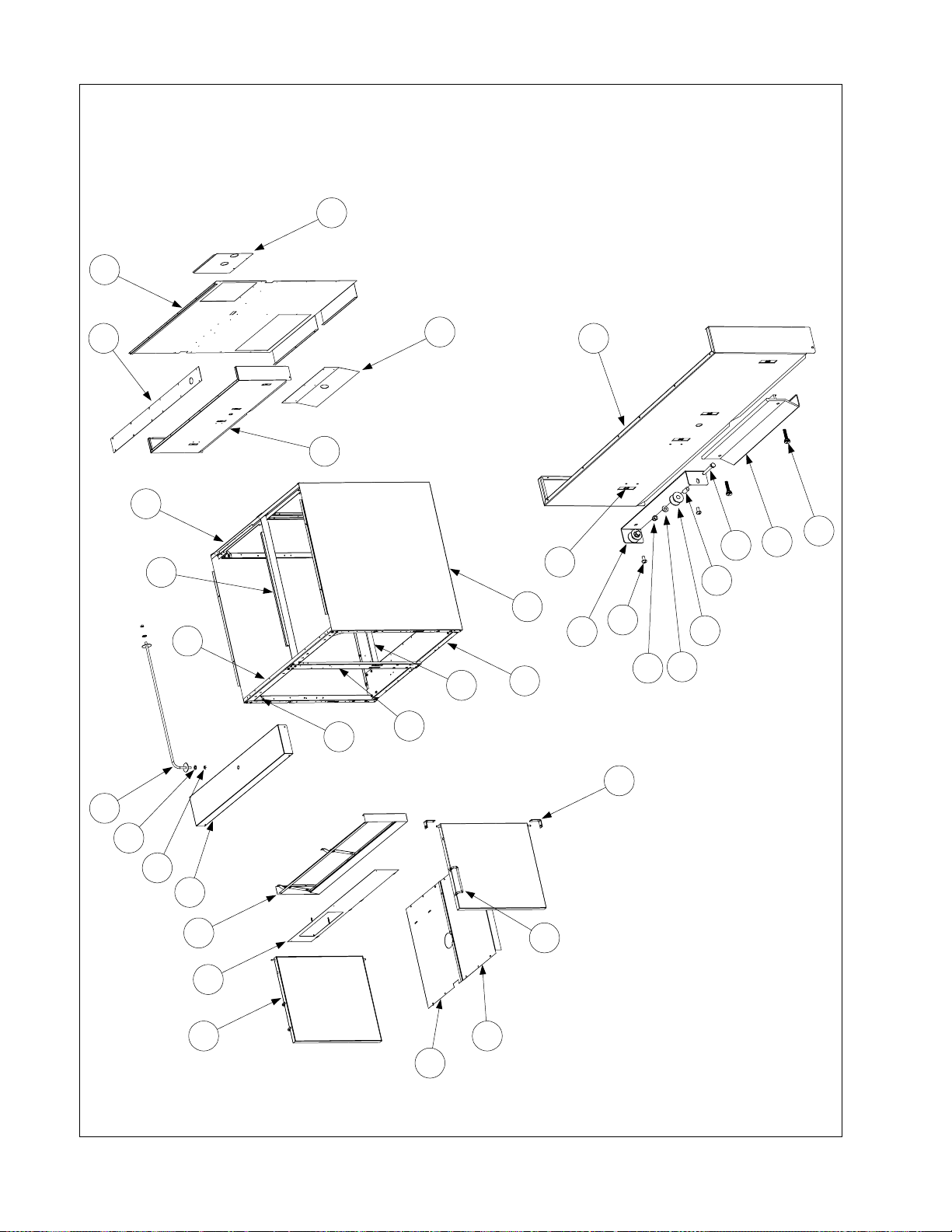
CABINETRY
10
Showing Attached
Detail of Backsplash
32
Components
33
9
13
12
5
7
6
11
8
2
1
12
26
34
27
31
25
30
28
29
4
14
15
16
17
18
19
20
3
22
21
24
23
6-22
Page 55

ITEM PART # COMPONENT
1 210-0815 Channel, Front or Rear Base
* 806-5209 Leg Pad Assembly (on bottom of Item 1, for mounting casters)
2 210-0816 Channel, Side Base
3 900-7198 Post, Door
4 900-1552 Gusset (Corner Brace)
5 900-7389 Brace, Top Rear
6 900-7390 Brace, Top Front
7 900-7391 Divider, Cabinet
8 Side, Left or Right Cabinet
910-7377 Stainless Steel
900-7377 Cold Rolled Steel (Painted)
9 900-7422 Back, Cabinet
* 826-1374 Screw, #10 x ½-inch Hex Washer Head (large cabinet screw) (Pkg of 25)
10 900-1750 Panel, Plumbing Access
* 826-1371 Screw, #8 x ½-inch Hex Head (access panel screw)
11 900-4645 Shield, Heat
12 210-0007 Backsplash
13 210-0215 Plate, Faucet Mounting
* 809-0740 Screw, #10 x ½-inch Phillips Truss Head (faucet plate and topcap screw)
14 810-1838 Rod, Basket Pivot
15 809-0200 Washer, ½-inch Flat
16 809-0063 Nut, ⅜-16 Jam
17 824-0801 Topcap
18 806-5487 Frame, Control Panel
19 823-2946 Panel, Control
20 806-9744 Door Assembly, Left or Right (does not include handle or hinges)
21 810-1402 Handle, Wire Form Door
* 809-0266 Screw, #10 x ½-inch Phillips Truss Head (door panel and handle screw)
22 810-1508 Hinge, Universal Door
23 210-0817 Shield, Left Moisture
24 210-0818 Shield, Right Moisture
25 910-4831 Bracket, Basket Lift Roller
26 809-0508 Bolt, ¼-20 x 1 ¼-inch Hex Head
27 810-0374 Spacer, Basket Lift Roller Tubular
28 810-0194 Roller, Basket Lift
29 809-0190 Washer, ¼-inch SS Flat
30 809-0047 Nut, ¼-20 Hex Head Cap
31 809-0127 Screw, ¼-20 x ½-inch Slotted Round Head
32 803-0028 Hanger, Basket (for wire-form hanger use 810-2229)
33 809-0171 Thumbscrew, Basket Hanger
34 826-1351 Retainer, ¼-20 Nut (Nutsert) (Pkg of 10)
* Not illustrated.
6-23
Page 56

13
12
11
10
8
COOKPOT, RINSE TANK,
AND DRAIN COMPONENTS
9
28
29
32
31
Mounting Hardware
Detail of High-Limit Thermostat
27
2
1
26
25
24
21 22 23
20
30
14
15
16
17 18 19
7
5 6
3
4
6-24
Page 57

ITEM PART # COMPONENT
1 823-2937SP Cookpot Assembly (for 17EMCS (McDonald’s), use 823-3827SP)
2 823-1994SP Rinse Tank Assembly
3 806-7552SP Water Level Sensor Assembly
4 900-5045 Retainer, Cookpot Front Insulation
* 816-0152 Insulation, Cookpot Front (behind Item 4)
5 900-1762 Retainer, Insulation
6 826-1376 Nut, 10-32 Hex Head Keps (Pkg of 10)
7 807-3333 Probe, Temperature
8 210-0681 Guard, Temperature Probe
9 807-2466 Thermostat, High-Limit
10 807-3814 Element, 208V 8.625kW (for 230V, use 807-3815; for 240V, use 807-3816)
11 810-0976 Nozzle
12 N/A Guard, Water Level Sensor (part discontinued; no longer used)
13 809-0047 Nut, ¼-20 Cap (secures Item 12 on units built before February 2001)
14 813-0451 Nipple, 1 ¼-inch NPT x 12-inch Chromed Brass
15 813-0453 Nut, 1 ¼-inch NPT Chromed Stainless Steel Slip
16 813-0148 Nipple, 1 ¼-inch NPT x 6 ¼-inch NPT
17 813-0070 Elbow, 1 ¼-inch NPT 90º
18 813-0400 Nipple, 1 ¼-inch NPT x 2-inch
* 813-0391 Nipple, 1 ¼-inch NPT Close (connects cookpot drain valve and Item 19)
19 813-0394 Tee, 1 ¼-inch NPT
20 813-0146 Nipple, 1 ¼-inch NPT x 4 ¼-inch
21 813-0518 Nipple, 1 ¼-inch NPT x 4-inch
22 813-0395 Union, 1 ¼-inch NPT
23 813-0144 Nipple, 1 ¼-inch NPT x 3 ¾-inch
24 813-0554 Nipple, 1 ¼-inch NPT x 7-inch
25 814-0047 Sleeve, Red Drain Valve Handle
26 910-9527 Handle, Drain Valve
27 810-1825 Valve, 1 ¼-inch NPT Drain
28 823-2022 Strainer
29 910-2042 Clamp, Element
30 910-5214 Support, Element
31 910-2097 Bracket, High-Limit
32 809-0769 Screw, #8 X ⅜-inch S/S Hex Washer Slot Head
* 809-0204 Washer, Teflon (fits between Item 10 and inside face of Cookpot)
* 809-0063 Nut, ⅜-16 Jam (secures Drain Valve Handle to Drain Valve)
* Not illustrated.
6-25
Page 58

20
ELECTRONICS
21
7 8
6
18
24
23
1716
19
22
31
32
15
30
25
1
26
33
34
2
13
12
3
9
14
10 11
35
36
4
5
27
28
21
1
2
3
4
5
6
7
8
9
10
11
12
13
14
15
1C BLK
2C BLK
3C BLK
4C BLK
5C BLK
6C BLK
7C BLU
8C WHT
9C BLU
10C BLK
11C BLK
12C BLK
15C WHT
1
2
3
4
5
6
7
8
9
10
11
12
13
14
15
29
38 39
37
1
2
3
4
5
6
7
8
9
10
11
12
13
14
15
21C ORG
22C GRN/YLW
23C BRN
24C ORG
25C ORG
26C RED
28C BRN
30C RED
32C BRN
1
2
3
4
5
7
8
9
1
2
3
4
5
6
1H BLK
2H BLK
3H BLK
4H BLK
5H BLK
6H BLK6
41C WHT
42C WHT
43C BLK
40
42 43
1
2
41
3
4
5
6
1
2
3
4
5
6
1H BLK
2H BLK
3H BLK
4H BLK
5H BLK
6H BLK
51C WHT
52C WHT
53C BLK
6-26
Page 59

ITEM PART # COMPONENT
* 106-0385 Computer, 17ECS
* 824-0856 Starch Shield (mounts to back of control panel to protect computer)
1 807-1555 Fuse, 5 Amp
2 807-1308 Holder, Fuse
3 809-0328 Screw, 4-40 x ¼-inch Slotted Pan Head
4 809-0237 Nut, 4-40 Hex Head Keps
5 807-0680 Transformer, 208-240VAC/24VAC 50/60Hz 43VA
6 807-3996 Relay, 75 Amp 280V SPST-NO Solid State
* 815-0554 Compound, Heatsink (GC Thorsen 10-8109)
7 807-0037 Tab, Faston 6.35 (.250) Series
8 809-0096 Screw, 6-32 x ⅝-inch Binding Slotted Head
9 807-1396 Relay, 24VDC SPDT
10 809-0102 Screw, 8-32 x ⅜-inch Slotted Truss Head
11 809-0247 Nut, 8-32 Hex Head Keps
12 807-2082 Switch, Non-Illuminated Rocker
13 802-1793A Label, ON/OFF
14 810-1202 Contactor, 3 Pole 600VAC 40 Amp
15 807-2464 Block, Delta Power
16 807-0070 Terminal, Ground Lug
17 802-0742B Label, Ground
18 807-2749 Heatsink
19 900-2752 Plate, Cordset
20 900-5895 Top, Triac Contactor Box
21 809-0359 Screw, #8 x ¼-inch Slotted Hex Washer Head
22 200-0008 Box, Triac Contactor
23 900-5785 Rear, Triac Contactor Box
24 900-8239 Rear, Split Triac Contactor Box
25 809-0117 Screw, 10-32 x ⅜-inch Slotted Truss Head
26 200-0180 Brace, Contactor Box Rear
27 200-0181 Brace, Contactor Box Front
28 826-1374 Screw, #10 x ½-inch Hex Head
29 900-5445 Cover, Contactor Box Front
30 200-0001 Bracket, Connector
31 807-0804 Connector, 15-pin Male
32 807-0875 Connector, 15-pin Female (Panel Mount)
33 807-2135 Connector, 6-pin High-Amp Male
34 807-2136 Connector, 6-pin High-Amp Female
35 807-2137 Connector, 9-pin High-Amp Male
36 807-2138 Connector, 9-pin High-Amp Female
37 806-3660 Sound Device, High-Output
38 106-0144 Harness, Computer to Contactor Box 15-pin Wiring
39 106-0158 Harness, Contactor Box Internal 15-pin Wiring
40 106-0157 Harness, Element to Contactor 9-pin Wiring
41 106-0156 Harness, Element to Contactor 6-pin Wiring
42 106-0159 Harness, Basket Lift Relay 6-pin Wiring
43 106-0160 Harness, Basket Lift to Contactor Box 6-pin Wiring
* Not illustrated.
6-27
Page 60

WATER SUPPLY SYSTEM COMPONENTS
10
14
11
13
1
4
7 8
6
2
3
9
4
5
ITEM PART # COMPONENT
1 810-0907 Elbow, ⅜-inch NPT Compression
2 910-2513 Tubing, Solenoid Valve to Cookpot ⅜-inch Stainless Steel
3 806-5565 Valve Assembly, 24VAC 60Hz Solenoid
4 813-0302 Elbow, ⅜-inch Tube to ¼-inch NPT 90º Brass Male
5 813-0472 Nipple, ¼-inch NPT x 2.5-inch Brass
6 900-1905 Mount, Solenoid Valve
7 813-0022 Nipple, ½-inch NPT x Close
8 809-0454 Nut, ½-inch Conduit
9 810-1208 Valve, Pressure Regulator
10 900-1898 Tube, ⅜-inch Water Line
11 813-0449 Tee, ¼-inch NPT Brass
12 813-0448 Elbow, ¼-inch NPT 90º Brass
13 813-0473 Nipple, ¼-inch NPT x 4-inch Brass
14 813-0412 Faucet, Double Jointed Pantry
* 826-1132 Kit, Faucet Repair (contains two valve assemblies)
* Not illustrated.
12
6-28
Page 61

6.6 Wiring Diagram (17ECS)
ALL READINGS REFERENCED TO GRO UND WITH THE COMPUTER OP ERATING
COMPUTER CONTROL
27-33vdc WHEN OFF
WHEN HEATING
GROUND WHEN
NOT FILLING
24vac WHEN
FILLING
C2
24vac GND
HOT COM
POWER IN
21 3 5641079 14131211 15
BLK
1C
BLK
2C
NO VOLTAGE
HEAT
WATER
FILL
BLK
4C
BLK
6C
OPTIONAL
SOLENIOD
24 VAC
15C WHT
BLK
3C
AUTOFILL
CNC
HI LIMIT
WHT
8C
BLK
5C
BASKET LIFT
WHT
47C
BLK
TYPE 5AMP
TRANSFORMER
48C
59C WHT
58C BLK
57C
WHT
COM
LINE
250V 4500A
L2L3 L1
BLK
46C
BLK
44C
VARISTOR
WHT
42C
45C
BLK
WHT BLK
41C
43C
UP POSITION
BASKET LIFT
NO
WHT
52C
132
456
MOTORS
COM
WHT
NC
51C
GEAR
BLK
53C
SHOWN IN
BLU
DO NOT MEASURE
WATER LEVEL
PROBES
BASKET DOWN
BASKET UP
0 VOLTS
27-33vdc
BASKET LIFT
27-33vdc
RELAY
ON WATER TEMP.
DEPENDING
2-3vdc
8
SOUNDING
WHEN
3-5v
PROBE
TEMP.
NO VOLTAGE
S
7C
BLU
9C
C1
12 4 653 987 10 11 12 151413
YLW
ORG
BLK
10C
BLK
12C
RED
BLK11C
RED
WHT
HIGH WATER SENSOR
SOUND DEVICE
LOW WATER SENSOR
LOAD
RED
68C
ORG
4
23C
21C
ORG
BRN
GRN/
22C
24C
26C
60C
RED
ORG
25C
BRN
28C
RED
30C
BRN
32C
BA
5H4H6H
897
456
RED
NC
NO
RELAY 24vdc
RED
7
5
2
RED
63C
2H
3H
1H
132
1
+3
2
61C
4
1
+3
2
62C
4 +3
21
RED
67C
5H
3H
4H
6H
456
64C BLK
BLK65C
BLK66C
1H
2H
132
L R
8051288C
PROBE
6-29
Page 62

6.7 Wiring Diagrams (17EMCS)
6-30
Page 63

6-31
Page 64

THIS PAGE INTENTIONALLY LEFT BLANK.
Page 65

ELECTRIC COOKER MODELS 17EC, 17ECS, ESW AND EWBS
CHAPTER 7: ESW & EWBS SERVICE PROCEDURES & PARTS
7.1 Functional Description
The ESW series was the predecessor to the EWBS series. Both cookers are very similar in
construction and function. The cookers in the ESW series have rocker-switch controls only. These
cookers were configured as single units or as batteries of two units. The primary difference between
the two configurations is in the piping of the Autofill water supply system and the lack of the basket
lift and computer options on ESW units.
Cookers in the EWBS series may be configured with computer controls or with the rocker-switch
controls as used on the ESW cookers. E1WBS models consist of a single cooker. E2WBS models
consist of two single units battered together.
All models feature a 16.5-gallon (62.5-liter) stainless steel cookpot. The water in the cookpot is
heated by a 13-kilowatt heating element. Optional features include a swing-away jointed faucet and
automatic filling and skimming features (Autofill and Autoskim).
Units with Manual Controls (rocker-switches and a thermostat)
When the POWER switch is placed in the ON position, the white POWER indicator next to the
switch illuminates. If the red TROUBLE indicator illuminates at any time, there is a problem with
the high-limit thermostat. The unit will not heat until the problem with the high-limit thermostat has
been resolved. Anytime the POWER switch is in the ON position, logic circuits in the interface
board check for the presence of water in the cookpot. These circuits look for grounding of the water
level sensors caused by their contact with water in the cookpot.
If the interface board senses that the cookpot is not full, (i.e., the upper water level sensor is not in
contact with water) it signals the normally closed solenoid valve on the water supply line to open.
When the interface board senses that water level in the cookpot is full, (i.e., water contacts the upper
water-level sensor), it signals the solenoid valve to close. Anytime the water level in the cookpot
drops below the upper water-level sensor, the interface board signals the solenoid valve to open to
refill the cookpot to the proper level.
When the HEAT CYCLE switch is placed in either the BOIL or the SIMMER position, if water is in
contact with the lower water level sensor, the interface board signals the contactor coil to close,
energizing the heating element. If the switch is placed in the SIMMER position, the interface board
closes or opens the contactor coil (and thus energizes or de-energizes the element) to maintain the
water in the cookpot at the temperature set with the thermostat knob. If the switch is placed in the
BOIL mode, the element remains energized until the switch is placed in the IDLE or the SIMMER
mode. If the switch is placed in the IDLE mode, power is supplied to all components of the unit
except the heating element. The Autofill feature, the faucet switch, and the skim switch are
functional anytime the power switch is in the ON position, regardless of the position of the heat
cycle switch.
7-1
Page 66

NOTE: The cooker has a high-limit safety. If the water in the cookpot falls below the low-waterlevel sensor but the sensor remains grounded for whatever reason (thereby allowing the element to
continue to heat), the high-limit switch will open when the element temperature reaches 400 ±15ºF.
This cuts off power to the element.
Units with Computer Controls
When the computer POWER switch is pressed, a logic circuit in the computer checks the water level
in the cookpot. A normally closed solenoid valve on the water supply line automatically opens if the
upper water-level sensor is not grounded by contact with water in the cookpot. Water will continue
to be added until the upper water level sensor is grounded by contact with water in the cookpot. If
there is sufficient water in the cookpot to cover the heating element (i.e., the lower water level sensor
is grounded by contact with water in the cookpot), the computer signals the contactor coil to close,
thereby energizing the heating element. If the temperature of the water in the cookpot is below the
cooking setpoint temperature programmed into the computer, -ºlo appears in the computer’s LED
display. If the temperature of the water in the cookpot is within 11ºF (6ºC) of the programmed
setpoint, “- - - -” appears in the computer’s LED display.
If the SIMMER mode is selected by pressing the R button, logic circuits in the computer monitor
the temperature of the water and cycle power to the element on and off to maintain the temperature
at the setpoint programmed into the computer. (See Chapter 3 for instructions on adjusting the
setpoint.) If the BOIL mode is selected by pressing the L button, the heating element remains
continuously energized until the SIMMER mode is again selected.
NOTE: The cooker has a high-limit safety. If the water in the cookpot falls below the low-waterlevel sensor but the sensor remains grounded for whatever reason (thereby allowing the element to
continue to heat), the high-limit switch will open when the element temperature reaches 400 ±15ºF.
This cuts off power to the element.
The Autoskim feature is activated by placing the SKIM switch in the ON position. When the feature
is activated, a logic circuit in the computer automatically opens the solenoid valve in the water
supply line for three seconds every minute until the option is turned off by placing the switch in the
OFF position.
On units equipped with faucets, the faucet is turned on by placing the FAUCET switch in the ON
position. This opens a dedicated normally closed solenoid valve on the faucet water line. The
solenoid valve remains open until the switch is placed in the OFF position.
When a product button is pressed to initiate a cooking cycle, the programmed cook time appears in
the LED display and begins to count down. When the specified cook time has elapsed, an audible
alarm sounds and the associated product button flashes. Simultaneously, logic circuits in the
computer activate the appropriate basket lift motor, lowering the basket into the cookpot. As the
motor drives the basket lift arm down, a cam attached to the motor eventually loses contact with a
roller-activated microswitch and power to the motors is cut. When the computer times out, logic
circuits reverse the switch positions so that the motor circuit is again completed and the motor is
restarted, raising the basket from the cookpot. At the fully raised position, the cam again makes
contact with the microswitch, cutting power to the motor and stopping the lift in the up position.
7-2
Page 67

7.2 Accessing Equipment for Servicing
DANGER
Moving this equipment while it is filled with hot water may cause spilling or
splattering of the hot water. Always drain the cookpot before attempting to relocate
this equipment for servicing.
1. Disconnect the unit from the electrical power supply and from the water supply.
2. Remove any attached restraining devices.
3. Relocate the unit for service accessibility.
4. After servicing is complete, reconnect the unit to the water supply, reattach restraining devices,
and reconnect the unit to the electrical power supply.
7.3 Replacing Equipment Components
7.3.1 Replacing the Computer
See Section 5.3.
7.3.2 Replacing Electronic Components Other than the Computer
1. Drain the cookpot and disconnect the cooker from the electrical power supply.
2. Remove the cover from the component box. Refer to the illustration below to locate the
component to be replaced.
Power Block
24V Transformer (all units)
24V Transformer (units w/Basket Lifts only)
Contactor
3. On the component to be replaced, make a note of the wiring connection points.
4. Disconnect the wires and remove the failed component. Install the replacement component and
reconnect the wiring in accordance with the notes made in Step 3 or with the wiring diagram on
the door of the unit.
5. Replace the component box cover, being sure to reconnect the ground wire. Reconnect the
cooker to the electrical power supply.
7-3
Page 68
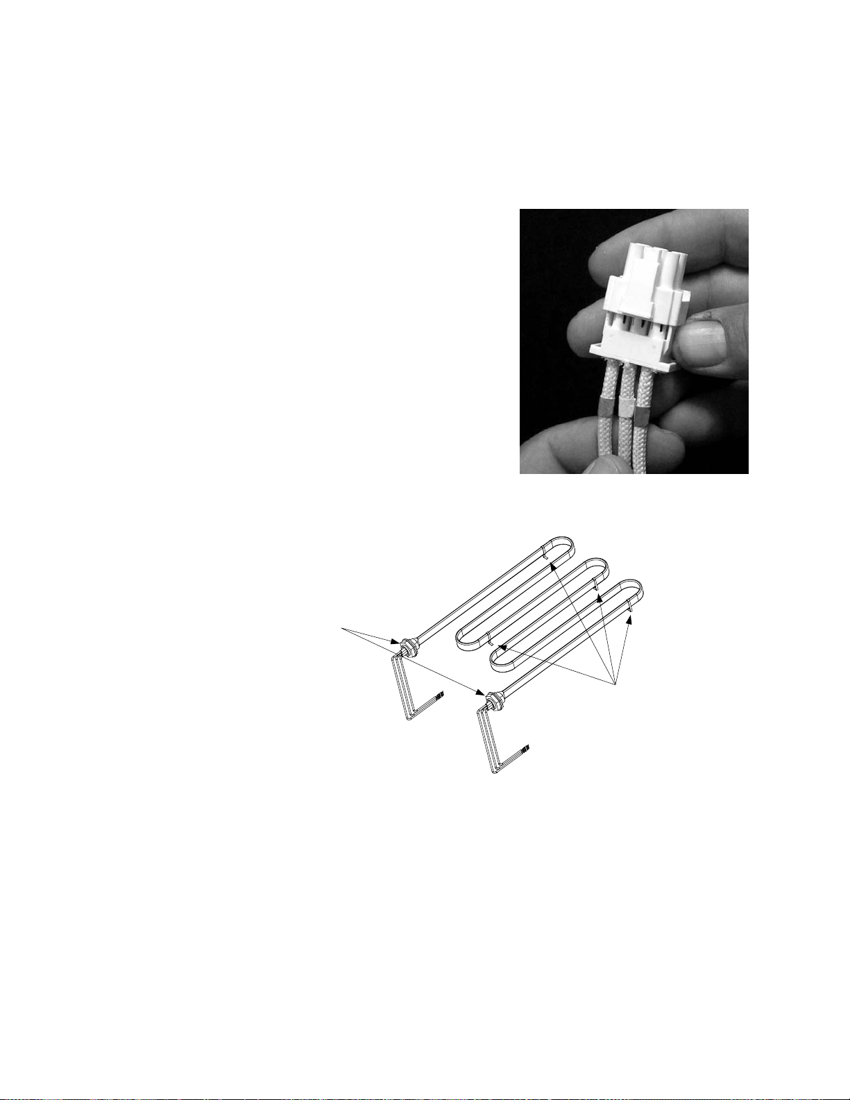
7.3.3 Replacing the Heating Element
1. Drain the cookpot and disconnect the cooker from the electrical power supply. Disconnect the
unit from the water supply at the rear of the cooker. Remove the basket lift arms from the unit.
2. Reposition the cooker to allow clear access to the rear of the unit. Remove the cabinet back (on
units with basket lifts, remove all three back panels).
3. Unplug the 6-pin element connector from the rear of the
contactor box. Depress the locking tabs on each side of the
connector and extend it to release the element leads (see
photo at right). Pull each of the leads out of the connector,
being careful not to damage the connector in the process.
4. If the bundle of element leads is enclosed in a fiberglass
insulating sheath, cut the wire ties securing the sheath in
place, and remove and discard it; it is no longer required.
Inside the cookpot, cut the metal wire ties that secure the
high-limit thermostat to the element, being careful not to
bend the thermostat in the process.
5. Remove the brass nuts that secure the element in the cookpot and lift the failed element from the
cookpot. Recover the Teflon washers from the failed element for use on the replacement.
Remove these nuts to dismount
element from cookpot.
Standoffs
6. Position the replacement element in the cookpot with the standoffs on the bottom of the cookpot.
Thread the element leads through the Teflon washers recovered from the failed element. Secure
the element in place with the nuts removed in Step 5.
7. Secure the high-limit thermostat against the inside of the leg of the element with two metal wire
ties.
8. Insert the pins on the element leads into the element connector in accordance with the illustration
on the following page. Each element lead is marked with a number that corresponds to the hole
in the connector into which it should be inserted. The insulation on the lead will be flush with
the face of the plug when properly positioned. When all leads are positioned correctly, close the
connector and verify that the tabs are locked in place.
7-4
Page 69

Hole 6
Lead 1
Note D-shaped pin and
"pip" identifying Hole 1.
9. Bundle all six element leads together and secure with plastic wire ties close to the element and
connector, and in the middle.
10. Plug the connector into the contactor box. Reverse Steps 1 and 2 to complete the procedure.
7.3.4 Replacing the High-Limit Thermostat
1. Drain the cookpot and disconnect the cooker from the electrical power supply. Disconnect the
unit from the water supply at the rear of the cooker. If the unit is equipped with basket lifts,
remove the basket lift arms. Cut the metal wire ties securing the thermostat tube to the element.
2. Reposition the cooker to allow clear access to the rear of the unit. Remove the cabinet back (on
units with basket lifts, remove all three back panels).
3. At the rear of the cookpot, loosen the small compression nut, then unscrew the large fitting from
the cookpot. Pull the thermostat tube out through the rear of the cookpot.
Loosen the small
compression nut first.
Unscrew the large fitting
only after loosening the
small compression nut.
4. Detach the high-limit thermostat leads (5C and 8C) from the thermostat. Remove the two screws
securing the thermostat to the mounting bracket and remove the thermostat assembly from the
cabinet. (NOTE: It is not necessary to remove the bracket.)
5. Loosen the small compression nut in the large fitting on the replacement thermostat so that the
large fitting will move freely on the capillary tube (the thin, flexible tube). Carefully insert the
replacement thermostat into the cookpot, being careful not to bend the thermostat tube. Position
the tube along the inside of the left leg of the element (as viewed from the front of the cooker)
and secure it in place with two metal wire ties. Apply thread sealer to the large fitting and screw
the fitting securely into the cookpot. When the large fitting is tight, pull gently on the capillary
tube to remove any slack, then screw the small compression nut into the large fitting and tighten.
7-5
Page 70

6. Coil the capillary tube as necessary to achieve a neat installation and attach the terminal block to
the mounting bracket using the screws removed in Step 4. Connect thermostat lead 5C (black) to
the normally closed (NC) terminal and 8C (white) to the common (C) terminal.
Common (C) Terminal
(Note open side.)
Normally Closed (NC) Terminal
(Note closed side.)
7. Reverse Steps 1 and 2 to complete the procedure.
7.3.5 Replacing a Water-Level Sensor
Drain the cookpot and disconnect the cooker from the electrical power supply. Disconnect the
sensor lead from the sensor, remove the nuts securing the sensor in place, and remove the sensor.
Install the replacement sensor as illustrated below and reconnect the lead.
Insulator must seat in
hole before nut is
tightened.
Inside of cookpot.
7.3.6 Replacing the Operating Thermostat or Temperature Probe
Units with Manual (Thermostat) Controls
1. Drain the cookpot and disconnect the cooker from the electrical power supply.
2. Disconnect the rocker-switch wires from the terminals of the thermostat body.
3. Loosen the Allen screw in the thermostat control knob and slip the knob off the thermostat shaft.
Remove the two screws securing the thermostat body to the mounting bracket and remove the
thermostat body from the mounting bracket.
4. At the cookpot, loosen the small nut in the center of the temperature probe fitting, then unscrew
the fitting from the cookpot. Inside the cookpot, remove the probe cover, push the probe out of
its retaining bracket, and withdraw the probe from the cookpot.
5. Verify that the small nut in the center of the replacement temperature probe fitting is loose and
that the fitting spins easily around the capillary tube. Pass the thermostat bulb through the hole
in the cookpot and position it under the lower portion of the retaining bracket.
7-6
Page 71

6. Carefully work any slack in the capillary tube back out of the hole in the cookpot. Apply thread
sealer to the threads of the replacement temperature probe fitting and screw the fitting into the
cookpot. When the fitting is tight, verify that all slack in the capillary has been worked back
out of the cookpot and that the bulb is correctly positioned under the lower portion of the
retaining bracket. Then, and only then, tighten the small nut in the center of the fitting. NOTE:
Tightening the small nut crimps the internal compression fitting onto the capillary and
prevents any further movement of the capillary through the large fitting.
Tighten the small
compression nut last.
Tighten the large fitting
before tightening the
small compression nut.
7. Position the thermostat body in the mounting bracket with the terminals to the left and reinstall
the two screws removed in Step 3. Reinstall the thermostat knob.
8. Reconnect rocker-switch wires 20C and 35C to the lower terminal of the thermostat body;
reconnect wire 15C to the top terminal. Reinstall the probe cover to complete the procedure.
Attach wire15C here.
Attach wires 20C and 35C here.
Units with Computer Controls
1. Drain the cookpot and disconnect the cooker from the electrical power supply.
2. Remove the screws from the upper corners of the control panel and open the panel by allowing it
to swing downward.
3. Disconnect the 12-pin connector from the interface board and, using a pin pusher, push out the
temperature probe leads from holes 6 and 8 on the connector.
4. Remove the temperature probe by unscrewing it from the front of the cookpot.
5. Apply thread sealer to the replacement probe and screw it securely into the cookpot.
6. Insert the probe leads into holes 6 and 8 of the 12-pin connector (there is no polarity; either lead
may be inserted into either hole [see illustration at top of next page]). Pull gently on each lead to
ensure it is firmly seated.
7-7
Page 72

Note D-shaped pin and
rib identifying Hole 1.
Hole 6
Hole 8
7. Reattach the 12-pin connector to the interface board, close the control panel, and replace the two
screws removed in Step 2.
7.3.7 Replacing the Pressure Regulator or Solenoid Valve
1. Drain the cookpot and disconnect the cooker from the electrical power supply. If necessary,
reposition the cooker to allow free access to the component to be replaced. Turn off or
disconnect the water supply to the cooker. If replacing an Autofill system pressure regulator or
solenoid valve on a unit equipped with basket lifts, the basket lift upper rear panel must be
removed.
2. Loosen the compression fittings on the water lines running to and from the regulator or solenoid
valve and remove the component from the unit. (NOTE: If the solenoid valve is mounted
adjacent to the regulator, disconnect the solenoid leads and remove both the regulator and
solenoid valve from the unit.)
TYPICAL WATER SUPPLY SYSTEM CONFIGURATIONS
Double Unit without
Basket Lifts
Single Unit without
Basket Lifts
Single Unit with
Basket Lifts
3. If replacing a regulator, adjust the replacement regulator output pressure to not more than 40 PSI
(28.15 kg/cm
2
) before installation in the cooker.
4. Recover the fittings from the failed component (regulator or solenoid valve) and install them on
the replacement, using thread sealer on all connections.
5. Reverse Steps 1 and 2 to complete the procedure, being sure to apply thread sealer to all
connections.
7-8
Page 73

7.3.8 Replacing the Water Faucet
1. Drain the cookpot and disconnect the cooker from the electrical power supply.
2. Turn off the water supply to the cooker and disconnect the incoming faucet water line where it
attaches to the pipe nipple at the pressure regulator. Reposition the cooker to gain clear access to
the rear of the cooker.
3. Remove the cabinet back (or, if the unit is equipped with basket lifts, remove the upper rear
panel).
4. Disconnect the water supply line at the compression fitting where it attaches to the faucet
assembly. Remove the large nut to dismount the faucet assembly from the cabinet.
Remove this nut to dismount
faucet assembly from cabinet.
Loosen this nut to separate
water line from faucet assembly.
5. Reverse Steps 1-4 to complete the procedure.
7.3.9 Replacing a Basket Lift Motor or Microswitch
1. Disconnect the cooker from the electrical power supply, disconnect the cooker from the
incoming water supply, and remove the basket lift arms from the lifter rods.
2. Remove the screws from the upper corners of the control panel and open the panel by allowing it
to swing downward. Unplug the basket lift wiring harness from the 5-pin connector on the
interface board.
3. Reposition the cooker to gain access to the rear. Remove all three panels from the rear of the
basket lift housing, and disconnect the lifter rods from the lifter cams (bell cranks). Slip the lifter
rods down and out of the assembly.
Lifter Rod
Remove the leveling screw, bushing,
and washer, then slip the lifter rod down
and out of the assembly.
7-9
Page 74

4. Remove the four bolts securing the motor mount to the frame, then remove the motor and mount
assembly from the unit. NOTE: It is possible to replace a motor or the microswitch without
removing the motor and mount assembly, but it is much more difficult.
5. Dismount the motor or microswitch as shown below and install the replacement.
NOTE:
The right motor and microswitch
dismount in the same way as the left.
Loosen setscrew in bottom
of cam (bell crank).
6. Reverse Steps 1-4 to complete the procedure.
7.3.10 Replacing the Cookpot
1. Drain the cookpot and disconnect the unit from the electrical power supply.
2. If so equipped, remove the faucet assembly from the cooker in accordance with Steps 1-4 of
Section 7.3.8.
3. Remove the screws from the upper corners of the control panel and open the panel by swinging it
downward.
On units with manual (thermostat) controls:
a. Disconnect the water level sensor leads at the cookpot terminals. Disconnect all wiring from
the control panel switches and light, and then remove the control panel from the unit.
b. Unplug the 4- and 6-pin connectors from the interface board. Disconnect all wiring from the
terminal block mounted next to the interface board.
c. Remove the interface board bracket from the unit.
d. Remove the temperature probe from the cookpot in accordance with Steps 4 through 6 of
Section 7.3.6 (Units with Manual (Thermostat) Controls).
e. Remove the thermostat mounting bracket with thermostat attached.
On units with computer controls:
a. Disconnect the water level sensor leads at the cookpot terminals. Disconnect all wiring to the
Skim switch (and to the Faucet switch, if present). Unplug the 15-pin connector from the
rear of the computer, and then remove the control panel from the unit.
7-10
Page 75

b. Unplug the 5- and 12-pin connectors from the interface board. Do not disconnect the water
level sensor leads from the interface board.
c. Remove the interface board bracket from the unit.
d. Using a pin pusher, push out the temperature probe leads from holes 6 and 8 on the 12-pin
connector.
4. Disconnect the Autofill water supply piping at the cookpot compression fitting.
5. Remove the screws that secure the topcap to the cabinet and remove the topcap from the unit.
On double units, remove the cookpot connecting strip.
6. Remove the screws attaching the standoff brackets to the cookpot.
Remove these screws
7. Unplug the element wiring harnesses from the rear of the contactor box. Disconnect the high-
limit thermostat leads from the thermostat body. Remove the screws securing the backsplash to
the cabinet and remove the backsplash.
8. With an assistant, lift the cookpot straight up and out of the cabinet. DO NOT ATTEMPT TO
REMOVE THE COOKPOT WITHOUT ASSISTANCE!
9. Invert the cookpot on a suitable work surface and remove the salvageable components (e.g.,
insulation, element, thermostats, drain plumbing, etc.). Install the recovered components on the
replacement cookpot or rinse tank, using thread sealer on all connections.
10. Reverse Steps 1 through 8 to complete the procedure, referring to the wiring diagram on the door
of the unit or at the end of this chapter when reconnecting wiring.
7-11
Page 76

7.4 Troubleshooting
Problems with this equipment may be grouped into five broad categories:
1. Failure or malfunction of a 24VAC Power-Supply System component.
2. Failure or malfunction of a Control System component.
3. Failure or malfunction of an Autofill/Autoskim System component.
4. Failure or malfunction of a Water Heating System component.
5. Failure or malfunction of a Basket Lift System component (on units so equipped).
Sections 7.4.1 through 7.4.5 briefly explain the functioning of each of the systems mentioned above.
Section 7.4.6 contains troubleshooting guides that provide systematic procedures to isolate and
identify the specific source of a problem. Wiring diagrams are located at the end of the chapter.
7.4.1 How the Power-Supply System Works
Line voltage is supplied to the system via a power cord that is plugged or hard-wired into the store’s
electrical service. The power cord is attached to a three-lug power terminal block. One set of three
wires delivers line voltage from the load side of the block to the line side of the contactor. A second
set of two wires delivers line voltage to the 24VAC transformer. Line voltage for the heating
element is delivered from the load side of the contactor through the 6-pin connector on the rear of
the contactor box. 24VAC for the remaining components is distributed to and from the contactor
box via the 15-pin connector on the front of the box.
On units with basket lifts, a separate set of two wires delivers line voltage from the terminal block to
the basket lift 24VAC transformer. From the transformer, the 24VAC is delivered to the interface
board via the 12-pin connector on the interface board. Line voltage for one side of the basket-liftmotor circuits is delivered directly to the motors from the terminal block via the 15-pin connector on
the front of the contactor box. Line voltage for the other side of the basket-lift-motor circuits is
supplied via the basket lift relays mounted on the interface board through the 5-pin connector on the
interface board. All line and 24VAC power except the line voltage for the elements is distributed to
and from the contactor box via the 15-pin connector on the front of the box.
7.4.2 How the Computer Works
The CM III computer provides the interface between the operator and the system components.
24VAC from the transformer is supplied through Pin 7 of the 9-pin connector on the interface board.
The 24VAC is rectified to 12VDC and delivered to the computer via Pins 1 and 3 of the 15-pin
connector. Internal circuitry senses the water temperature. Depending upon the conditions sensed,
the computer energizes or de-energizes the heating element (via the contactor coil) to control water
temperature. The computer also controls the lowering and raising of the basket lifts, and activates an
audible alarm to signal the operator that a cooking cycle has completed. The computer signals for
heat via Pin 4 of the 15-pin connector. The temperature probe connects to Pins 13 and 14 of the 15pin connector. The basket lift relays connect to Pins 7 (right) and 9 (left), and the sound device
connects to Pin 11 of the 15-pin connector.
7-12
Page 77

7.4.3 How the Autofill and Skim Systems Work
The heart of the automatic filling (Autofill) system is a normally closed solenoid valve that opens
when 24VAC is applied as a result of the loss of upper water-level sensor ground. The ground is lost
when the sensor is not in contact with water in the cookpot. Starch or lime build-up on the sensor
may keep a ground from forming. Therefore always make sure the sensor is clean and its lead is
firmly connected to Pin 1 of the 6-pin connector on the interface board (units with manual controls)
or connector J5 on the interface board (units with computer controls). Also, in order for the ground
to form, there must be some mineral content in the water (pure water is non-conductive).
Consequently, the units will not operate with distilled water. If distilled, highly filtered, or purified
water is used, add ⅛-cup of baking soda to the water each time the cookpot is emptied and refilled.
In units with manual controls, the 24VAC is supplied via Pins 1 and 2 of the 4-pin connector on
the interface board so long as the upper water-level sensor is not in contact with the water in the
cookpot. In units with computer controls, 24VAC is continuously supplied to one leg of the
circuit via Pin 6 of the 15-pin connector on the front of the contactor box. The other leg is supplied
via Pin 2 of the 12-pin connector on the interface board so long as the upper water-level sensor is not
in contact with water in the cookpot. In either case, when the water in the cookpot reaches the upper
water-level sensor, the sensor is grounded. This causes logic circuits in the interface board to cut the
24VAC to the solenoid, closing the valve.
If the SKIM switch is placed in the ON position, the logic circuits in the interface board are
bypassed and 24VAC is applied to the solenoid valve for as long as the switch is left in the ON
position.
7.4.4 How the Water Heating System Works
To prevent energizing the heating elements when there is no water in the cookpot, these units are
equipped with a low-water-level sensor. This sensor must be grounded by contact with water in the
cookpot before the control circuitry will apply power to the elements. Starch or lime build-up on the
low-water-level sensor may keep the ground from forming, therefore always make sure the sensor is
clean and its lead is firmly connected to J5 on the interface board. In order for the ground to form,
there must be some mineral content in the water (pure water is non-conductive). Consequently, the
units will not operate with distilled water. If distilled, highly filtered, or purified water is used, add
⅛-cup of baking soda to the water each time the cookpot is emptied and refilled.
In addition to the low-water-level sensor discussed above, the water heating system has six more
parts: the high-limit thermostat, the temperature probe, the contactor, the element, and a HEAT
CYCLE switch and manual thermostat, or a computer.
The high-limit thermostat functions as a normally closed switch. If the water in the cookpot falls
below the low-water-level sensor but the sensor remains grounded (for whatever reason), the high-
limit switch will open when the element temperature reaches 400ºF ±15 (204ºC ± 9). This cuts
power to the contactor coil and thus to the element.
The temperature probe is used only when the unit is in the simmer mode. When the operator
selects the simmer mode, logic circuits in the on the interface board or in the computer monitor the
temperature of the water and cycle power to the element (via the contactor coil) on and off as
7-13
Page 78

required to maintain the temperature at the setpoint programmed into the computer or set on the
thermostat knob.
The contactor is the terminal block to which the element leads are connected and where actual
contact is made between the leads and the line voltage. Built into the contactor is a 24VAC coil that
energizes when signaled by the computer or interface board that the water temperature is below the
setpoint. When it energizes, contact is made between the incoming line voltage and the element
leads, and line voltage is supplied to the element.
The element is a resistive heating device. That is, when voltage is applied to the element, it gets
very hot due to its resistance to current flow through it. The heat generated is transferred directly to
the water in which the element is immersed.
In units with manual controls, the three-position HEAT CYCLE switch controls how power is
supplied to the element. When the switch is in the:
• IDLE position, no power is supplied to the element at any time.
• BOIL position, power is supplied to the element continuously until the switch is placed in
another position.
• SIMMER position, power to the element cycles on if the water temperature is below the
temperature indicated by the thermostat knob. When the temperature reaches that indicated
by the thermostat knob, power to the element cycles off. This process continues until the
switch is placed in another position.
In units equipped with a computer, the computer is the interface between the operator and the other
components of the equipment. It controls the application of line voltage to the heating element via
the contactor. There are two modes of operation:
Simmer Mode, the signal from the computer is continuos and line voltage is applied to the
elements until the simmer setpoint programmed into the computer is reached, at which time the
signal ceases.
Boil Mode, the signal from the computer is continuous ceasing only when the unit is turned off
or placed in the simmer mode.
7.4.5 How the Basket Lift System Works
When a product button is pressed to start the cooking cycle, logic circuits in the computer activate
the appropriate basket lift motor, lowering the basket into the cookpot. As the motor drives the
basket lift rod down, a cam attached to the motor eventually loses contact with a roller-activated
microswitch and power to the motor is cut. When the computer times out, logic circuits reverse the
switch positions so that the motor circuit is again completed and the motor is restarted, raising the
basket from the cookpot. At the fully raised position, the cam again makes contact with the
microswitch, cutting power to the motor and stopping the lift in the up position.
7-14
Page 79

7.4.6 Technician Troubleshooting Guides
TROUBLESHOOTING THE 24VAC POWER SUPPLY SYSTEM
Verify that the power cord is
properly connected to the
electrical service and that
the circuit breaker is not
tripped.
On units with manual
controls, place the
POWER switch in the
ON position.
On units with computer
controls, place the
ON/OFF switch in the
ON position.
Was there an
audible snap from the
contactor indicating the
coil energized?
Yes
24VAC Power Supply
System is OK.
The primary indicator of a
problem with the 24VAC
Power Supply System is a
failure of the power light to
illuminate when the
POWER switch is placed
in the ON position or the
failure of the computer to
activate when the
computer ON/OFF switch
is pressed.
No
Is 24VAC present
across Pins 4, 5, and 6
of the 15-pin connector
on the front of the
contactor box?
No
Is line voltage
present on the line side of
the transformer?
No
Cause is loose or broken wiring,
or the electrical service circuit is
dead.
Causes are broken or loose wiring
or a failed contactor. If wiring and
Yes
connections are verified to be intact,
replace contactor.
Yes
Is 24VAC
present on the load side of
the transformer?
Transformer has
failed. Replace.
No
Yes
In units with manual controls, verify the
continuity of the POWER switch in the ON
position. Replace switch as required.
If the switch is OK, causes are broken
or loose wiring. Check connections and
replace wiring as required.
7-15
Page 80

TROUBLESHOOTING THE AUTOFILL SYSTEM
Verify that unit is connected to the
water supply and that water supply
Drain the water in the cookpot to a
level below the upper water-level
In units with computers, press the
is turned on.
sensor.
Place the POWER switch in the
ON position.
computer ON/OFF switch.
Did unit
begin to fill?
No
Remove the water-
level sensor guard
and thoroughly clean
the sensors.
Yes
Did unit
shut off when water
reached the upper water-level
sensor?
Did unit
begin to fill?
No
No
Is 24VAC present on
Pins 1 and 2 of the IFB
4-pin connector (manual controls)
or
Pin 2 of the IFB 12-pin
connector (computer
controls)?
Yes
Check connections and wiring
to solenoid valve. If wiring and
connections are intact, the valve
has failed. Replace.
Is 0 voltage present
on Pins 1 and 2 of the IFB
4-pin connector (manual controls)
or
Pin 2 of the IFB 12-pin
connector (computer
controls)?
Check sensor and wiring.
If they are NOT grounded,
the IFB has failed. Replace.
No
If they ARE grounded, repair
or replace as required.
Check sensor and wiring.
If they ARE grounded,
the IFB has failed. Replace.
No
If they are NOT grounded,
clean, repair or replace as
required.
Yes
Autofill system is OK.
Yes
Solenoid valve has
failed. Replace.
7-16
Page 81

TROUBLESHOOTING THE WATER HEATING SYSTEM
Each of the following checks is to be performed with the unit connected to the
electrical power supply, with the unit ON and calling for heat, and with at least
enough water in the cookpot to cover the lower water-level sensor.
CHECKING THE
HIGH-LIMIT
THERMOSTAT
Is resistance
between outside
terminals
1 ohm or less?
Yes
High-limit is OK.
CHECKING THE
ELEMENT
(24VAC Power Supply
verified to be OK..)
With sufficient water in the cookpot to cover the
heating element, place the POWER switch in
the ON position and the CYCLE switch in the
SIMMER position, OR press the computer ON/
OFF switch to the ON position.
No
High-limit has
failed. Replace.
CHECKING
THE TEMPERATURE
PROBE
(on units with computers
because water boils in
Simmer Mode or water is
too cool in Simmer Mode.)
Check probe resistance between Pins 6
and 8 on IFB 12-pin connector.
Resistance should be:
Approx 552 ohms @ 60ºF (16ºC)
Approx 655 ohms @ 100ºF (38ºC)
Approx 1000 ohms @ 212ºF (100ºC)
Check resistance between each pin and
ground. Resistance on BOTH should be
2 mega-Ohms or greater.
Are BOTH readings
within specification?
Yes
Probe is OK.
No
Probe is open or is
shorted. Replace.
Was there an
audible snap indicating the
contactor coil
energized?
Yes
Ohm out elements (Pins 1 & 6,
2 & 5, 3 & 4). If resistance
is NOT 15 ±3 Ohms, the element
has failed. Replace.
No
Is 24VAC
present on the
CYCLE switch
OR
on Pin 4 of the 15-pin
connector on
the IFB.
Yes
Probable causes,
in order of probabilty,
are failed switch or
contactor.
No
Probable causes, in
order of probabilty, are
failed computer or IFB.
Thermostat is open or
is shorted. Replace.
CHECKING
THE THERMOSTAT
(on units with manual
controls.)
Set thermostat knob to OFF position.
Check resistance across terminals.
Resistance should be infinite.
Set thermostat to its highest setting.
Check resistance across terminals.
Resistance should be less than 1 ohm.
No
Are BOTH
readings correct?
Yes
Thermostat
is OK.
7-17
Page 82

TROUBLESHOOTING THE BASKET LIFT SYSTEM
TROUBLESHOOTING
THE BASKET LIFT
With the basket lift
in the UP position, is 27-33VDC
present at Pin 7 or 9 of IFB 15-pin
connector (0 volts if in DOWN
position)?
Yes
With the basket lift
in the UP position, is line voltage
present at the NC (lower) terminal of
the microswitch (middle terminal if in
DOWN position)?
If the basket lift motors are activating, but the basket lift fails to raise
or lower, or if its movement is erratic, the probable cause is
jamming or binding of the basket lift rods. Apply a light-weight white
grease (such as Lubriplate
TM
) to the rods. If this does not correct
the problem, check for bent or otherwise damaged rods and links,
and for loose bellcranks.
No
Computer has failed.
Replace.
IFB has failed.
Replace.
No
Yes
With the basket lift in the same
position as for the previous check, is
line voltage present at the Common
terminal of the switch?
Yes
Motor has failed.
Replace.
No
Switch has failed.
Replace.
7-18
Page 83

7.5 Parts List
ACCESSORIES
1
8
9
2
5
10
3
6
11
15
12
13
4
7
14
ITEM PART # COMPONENT
1 823-1910 Basket, Bulk Cooking, Full Size (cannot be used with basket lifts)
2 806-7569 Cover
3 910-2545 Strainer Board
4 824-0587 Cookpot Top Connecting Strip (used on double units only)
5 Cup, Single Portion
803-0018 Beige
803-0260 White
6 823-2754 Basket, Bulk Cooking, Half Size (for use with basket lifts)
7 910-2766 Pan Insert
8 810-1008 Hose, Water Supply, with Quick Disconnect Fittings (Swirl)
9 810-1463 Hose, Water Supply, with Quick Disconnect Fittings
10 803-0155 Basket, Sauce Packet
11 803-0234 Brush, Probe Cleaning
12 803-0233 Rack, Basket Support
13 826-1117 Caster without Brake, 5-Inch (includes mounting hardware)
14 826-1118 Caster with Brake, 5-Inch (includes mounting hardware)
15 826-0900 Chain Restraint Kit
* 803-0259 Rack, 4 Portion Cups (for use with basket lifts)
* 803-0218 Rack, 9 Portion Cups (cannot be used with basket lifts)
* Not illustrated.
7-19
Page 84

BASKET LIFT COMPONENTS
39
41
40
38
5
3
37
13
12
7
9
4
6
10
11
35
8
33
34
20
14
32
18
15
31
17
25
23
21
16
19
36
28
29
30
27
26
24
22
2
1
7-20
Page 85

ITEM PART # COMPONENT
1 823-2753 Arm, Right Basket Lift (as viewed from front of unit)
2 823-2752 Arm, Left Basket Lift (as viewed from front of unit)
3 910-7420 Top, Basket Lift Enclosure
4 911-7417 Side, Basket Lift Enclosure Right
5 912-7417 Side, Basket Lift Enclosure Left
6 900-7421 Support, Basket Lift Rod Bushing
7 826-1363 Screw, 8-32 x ½-inch Slotted Truss Head (Pkg of 25)
8 902-1927 Bracket, Left Basket Lift Roller
9 901-1927 Bracket, Right Basket Lift Roller
10 809-0247 Nut, 8-32 Hex Keps
11 809-0508 Bolt, ¼ -20 x 1 ¼-inch Hex Head SS
12 810-0194 Roller, Basket Lift
13 809-0047 Nut, ¼-20 SS Hex Cap
14 809-0082 Ring, ¾-inch Truarc
15 810-0045 Bushing, Basket Lift Rod
16 807-0108 Motor, 240VAC Basket Lift
17 900-7416 Mount, Basket Lift Motor
18 809-0113 Screw, 8-32 x 1 ½-inch Slotted Truss Head
19 809-0050 Nut, 8-32 Hex
20 826-1358 Nut, 6-32 Hex (Pkg of 25)
21 812-0138 Insulation, Motor Mount (Fishpaper)
22 807-0240 Microswitch
23 809-0097 Screw, 6-32 x 1-inch Slotted Truss Head
24 810-0052 Cam (Bellcrank), Basket Lift
25 809-0194 Washer, 5/16-inch SAE Flat
26 809-0196 Washer, ⅜-inch SAE Flat
27 809-0063 Nut, Jam 3/8-16 Hex
28 810-0220 Spacer, Tubular, .493-inch OD
29 809-0203 Washer, ½-inch ID x ⅞-inch OD Nylatron Flat (Pkg of 10)
30 809-0155 Screw, 5/16-18 x ⅝-inch Leveling
31 826-1370 Screw, ¼-20 x 1 ¼-inch Slotted Round Head (Pkg of 10)
32 809-0076 Nut, ¼-20 x ¾-inch Expansion
33 920-6076 Link, Basket Lift
34 810-0170 Pin, ¼-inch x ⅝-inch Spring Dowel
35 810-0192 Rod, 19 ⅝-inch Basket Lift
36 807-0124 Bushing, Heyco
37 809-0127 Screw, ¼-20 x ½-inch Slotted Round Head
38 809-0719 Screw, #10 x ½-inch 410SS
39 900-8063 Panel, Upper Basket Lift Rear
40 900-7995 Panel, Middle Basket Lift Rear
41 900-7419 Panel, Lower Basket Lift Rear
7-21
Page 86

CABINETRY
38
37
15
33
41
14
16
13
9
40
7
8
39
6
11
10
2
17
18
22
36
35
34
disproportionately large for clarity.
NOTE: Items 33 through 38 are shown
19
20
21
5
12
25
4
3
30
31
32
29
1
27
28
26
24
23
7-22
Page 87

ITEM PART # COMPONENT
1 Side, Left or Right Cabinet
910-7377 Stainless Steel
900-7377 Cold Rolled Steel (Painted)
2 910-2914 Side, Double Unit Inner Cabinet
3 900-5023 Back, Cabinet
4 824-0633 Backsplash (units without basket lifts)
5 810-0044 Plug, ⅞-inch (used on units without basket lifts or faucets)
6 823-2105 Backsplash (used on units with basket lifts)
7 910-8355 Cover, Backsplash Top (used on basket lift units without faucet)
8 910-8060 Cover, Backsplash Top (used on basket lift units with faucet)
9 910-8058 Restrictor, Faucet Rotation (used on basket lift units with faucet)
10 900-1759 Bracket, Pot Hold Down
11 900-4654 Brace, Top
12 900-1552 Gusset (Corner Brace)
13 806-5260 Frame, Control Panel
14 910-7541 Topcap
15 823-2351 Topcap, Plate-Width (used on double units only)
16 900-2762 Support, Plate-Width Topcap
17 809-0266 Screw, #10 x ½-inch Phillips Truss Head (door panel and handle screw)
18 810-1402 Handle, Wire Form Door
19 806-3853 Door Assembly, Left or Right (does not include handle or hinges)
20 806-4487 Door Pin Assembly
21 810-1508 Hinge, Universal Door
* 826-1343 Spring, Door Hinge (Pkg of 10)
22 810-1105 Magnet, Door
23 806-5209 Leg Pad Assembly
24 900-7528 Channel, Left or Right Side Base
25 900-4655 Channel, Front or Rear Base
26 826-1374 Screw, #10 x ½-inch Washer Hex Head (Pkg of 25)
27 900-8273 Moisture Shield
28 816-0091 Grommet, 1¼-inch Drain
29 900-4645 Shield, Heat
30 910-5137 Plate, Battering (4.7-inch x 1.2-inch with 4 holes)
31 910-3122 Plate, Battering (10-inch x 1.2-inch with 6 holes)
32 910-0404 Plate, Battering (2-inch x 2-inch with 4 holes)
33 910-4831 Bracket, Basket Lift Roller
* 809-0127 Screw, ¼-20 x ½-inch Slotted Round Head (for mounting Item 33)
34 809-0508 Bolt, ¼-20 x 1 ¼-inch Hex Head
35 810-0374 Spacer, Basket Lift Roller Tubular
36 810-0194 Roller, Basket Lift
37 809-0190 Washer, ¼-inch SS Flat
38 809-0047 Nut, ¼-20 Hex Head Cap
39 810-2229 Hanger, Basket (replaced extruded aluminum hanger 803-0028, which is no longer available.)
40 809-0171 Thumbscrew, Basket Hanger
41 826-1351 Retainer, ¼-20 Nut (Nutsert) (Pkg of 10)
* Not illustrated.
7-23
Page 88

CONTROL COMPONENTS
1
3
5
6
2
8
9
10
7
11
12
13
14
4
20
15
17
ITEM PART # COMPONENT
1 809-0250 Nut, 6-32 Hex Head Keps
2 806-9100 Computer, CM III (for use on EWBS units only)
3 823-2760 Panel, Computer Control with Two Cutouts
4 823-2770 Panel, Computer Control with One Cutout
5 910-2454 Panel, Manual (Thermostat) Control
6 807-0495 Light, Red and White Split, 24V
7 807-2479 Switch, ON-OFF-ON Rocker (Non-Illuminating)
8 807-2082 Switch, ON-OFF Rocker (Non-Illuminating)
9 807-2273 Switch, ON-OFF Rocker (Non-Illuminating)
10 806-9413 Bracket, Interface Board Mounting
11 809-0238 Nut, 4-40 Hex Head
12 809-0360 Screw, #8 x ⅜-inch Washer Slotted Hex Head
13 810-1164 Block, Screwless Terminal
14 809-0354 Screw, 4-40 x ¾-inch Slotted Pan Head
15 Interface Board
806-6505 For use on units with manual (thermostat) controls.
806-9295 For use on units with computer.
16 809-0250 Nut, 6-32 Hex Head Keps
17 807-2272 Thermostat, Operating
18 900-5026 Bracket, Thermostat Mounting
19 810-0387 Knob, Control
* 802-1432C Label, Thermostat Dial (adhesive-backed)
20 806-4206 Probe, Temperature (for use on units with computers)
* Not illustrated.
16
18
12
19
7-24
Page 89

COOKPOT AND DRAIN COMPONENTS
14
6
15
2
3
4
5
11
10
26
1
16
22
23
24
13
12
17
18
9
25
7
21
19
20
ITEM PART # COMPONENT
1 Cookpot
823-2392SP Units with Manual Controls
823-2757SP Units with Computers
2 816-0152 Insulation, Cookpot Front
3 900-5405 Retainer, Cookpot Front Insulation
4 900-1762 Retainer, Insulation
5 826-1376 Nut, 10-32 Hex Head Keps (Pkg of 10)
6 806-7552SP Water-Level Sensor Assembly
7 Temperature Sensor
807-2272 Operating Thermostat (units with manual controls)
806-4206 Temperature Probe (units with computers)
8 807-2466 High-Limit Thermostat
9 809-0047 Nut, ¼-20 Cap
10 910-2927 Cover, Water-Level Sensor
11 810-0976 Nozzle
12 910-1038 Thermostat Guard (units with manual controls)
13 810-0738 Probe Guard (units with computers)
14 807-2440 Element, 208V 13kW Heating
15 809-0567 Tie Wrap, Metal
16 813-0391 Nipple, 1¼-inch NPT Close
17 813-0451 Nipple, 1¼-inch NPT x 12-inch Chromed Brass
18 813-0453 Nut, 1¼-inch NPT Chromed Stainless Steel Slip
19 813-0146 Nipple, 1¼-inch NPT x 4¼-inch
20 813-0070 Elbow, 1¼-inch NPT 90º
21 813-0394 Tee, 1¼-inch NPT
22 810-1825 Valve 1¼-inch NPT Drain
23 814-0047 Sleeve, Red Drain Valve Handle
24 910-9527 Handle, Drain Valve
25 809-0063 Nut, ⅜-16 Jam
26 809-0204 Washer, Teflon (between element and inside face of cookpot)
8
7-25
Page 90

ELECTRONICS
13
17
9
21
3
16
12
10
20 11
8
4 65
21 22
15
7
14
11
18
23
24
25
10
19
26
17
42C
59C
58C
54C
55C
41C
44C
40C
39C
72C
43C
25C
14C
28C
34C
38C
27C
16C
23C
25C
44C
22C
34C
28
27
29 30 31
42C
21C
41C
44C
40C
39C
72C
20C
30C
6H
5H
4H
3H
2H
1H
32 33 34
11C
12C
10C
9C
7C
7C
18C
5C
2C
19C
3C
4C
2C
1C
35 36 37
7-26
Page 91

ITEM PART # COMPONENT
1 807-0680 Transformer, 208-240VAC/24VAC, 50/60Hz, 43VA
2 809-0112 Screw, 8-32 x 1¼-inch, Slotted Truss Head
3 809-0247 Nut, 8-32 Hex Keps
4 807-0979 Transformer, 208-240VAC/12VAC, 50/60Hz, 20VA (for Basket Lift)
5 809-0104 Screw, 8-32 x ½-inch Slotted Hex Washer Head
6 809-0050 Nut, 8-32 Hex
7 810-1202 Contactor, 3-pole, 600V, 40 Amp
8 807-2465 Power Block
9 807-0070 Terminal, Ground Lug
10 807-2136 Connector, 6-pin High Amp Female (2 x 3)
11 807-0875 Connector, 15-pin Female (3 x 5)
12 900-5000 Back, Contactor Box
13 900-5001 Contactor Box
14 900-5027 Brace, Contactor Box Front
15 900-5028 Brace, Contactor Box Rear
16 900-0289 Bracket, Contactor Box (used with Moisture Shield [Item 27, Page 22])
17 809-0360 Screw, 8-32 x ⅜-inch Slotted Hex Washer Head Drill Point
18 809-0434 Screw, 8-32 x ⅜-inch Hex Washer Head Machine
19 900-5150 Cover, Contactor Box
20 807-0804 Connector, 15-pin Male (3 x 5)
21 807-0160 Connector, 12-pin Male (3 x 4)
22 807-0159 Connector, 12-pin Female (3 x 4)
23 807-2137 Connector, 9-pin Male (3 x 3)
24 807-2138 Connector, 9-pin Female (3 x 3)
25 807-2135 Connector, 6-pin High Amp Male (2 x 3)
26 807-0184 Connector, 6-pin Male (1 x 6)
27 807-3075 Connector, 5-pin Male (1 x 5)
28 807-2078 Connector, 4-pin Male (1 x 4)
29 806-9299 Harness, Contactor Box Internal (15-pin female connector with 10 leads)
30 806-9095 Harness, Contactor Box External (15-pin male connector with 6 leads)
31 806-9309 Harness, EWBS Computer (15-pin male connector with 7 leads)
32 806-8808 Harness, Contactor Box Internal (15-pin female connector with 6 leads)
33 806-9308 Harness, EWBS IFB to Components (12-pin male connector with 3 leads)
34 106-0156 Harness, Element to Contactor (6-pin female connector with 6 leads)
* 806-8807 Harness, Element to Contactor (9-pin female connector with 6 leads)
35 806-9096 Harness, ESW Interface Board (6-pin male connector with 6 leads)
36 806-9305 Harness, EWBS Basket Lift (5-pin male connector with 4 leads)
37 806-9097 Harness, ESW/EWBS w/o Basket Lift (4-pin male connector with 4 leads)
* Not illustrated.
7-27
Page 92

WATER SUPPLY COMPONENTS
4
3
4
11
9
1
11
2
2
8
1
Basket Lifts
Single Unit with
2
2
1
18
1
14
16
17
15
19
19
21
TYPICAL WATER SUPPLY CONFIGURATIONS
4
1
2
3
10
7
Basket Lifts
Single Unit without
1
20
(shown disproportionately large for clarity)
11
2
3
7
4
2
5
1
6
23
11
2
12
22
DETAIL OF PRESSURE REGULATOR AND SOLENOID COMPONENTS
13
Basket Lifts
1
Double Unit without
1
20
7-28
Page 93

ITEM PART # COMPONENT
1 810-1208 Valve, Water Pressure Regulator
2 806-7551 Valve Assembly, Solenoid
3 813-0513 Faucet, Double Jointed (with no cutoff valve)
4 910-2513 Tubing, Solenoid Valve to Cookpot
5 812-1292 Tubing, Regulator Valve to Right Solenoid Valve (used in double units)
6 812-1293 Tubing, Regulator Valve to Left Solenoid Valve (used in double units)
7 910-5149 Tubing, Solenoid Valve to Faucet
8 910-8011 Tubing, Regulator Valve to Solenoid Valve (units with basket lifts only)
9 910-8012 Tubing, Solenoid Valve to Faucet (units with basket lifts only)
10 813-0507 Coupling, ¼-inch NPT Brass
11 810-0907 Compression Fitting, ⅜-inch NPT to Tubing 90º Elbow
12 900-2915 Bracket, Pressure Regulator Valve (used in double units)
13 900-2917 Brace, Water Inlet (used in double units)
14 900-7991 Bracket, Pressure Regulator Valve (units with basket lifts only)
15 900-2916 Bracket, Pressure Regulator Valve (units without basket lifts only)
16 900-1905 Bracket, Solenoid Valve (units without basket lifts only)
17 809-0454 Nut, ½-inch Conduit
18 813-0472 Nipple, ¼-inch NPT x 2.5-inch
19 813-0471 Nipple, ¼-inch NPT x 1.5-inch
20 813-0450 Nipple, ¼-inch NPT x 2.0-inch
21 813-0448 Elbow, 90º ¼-inch NPT
22 810-1025 Compression Fitting, ¼-inch NPT to Tubing Straight
23 813-0495 Tee, ¼-inch NPT Male Branch to ¼-inch NPT Female
7-29
Page 94

7.6 Wiring Diagrams
Units with Manual (Thermostat) Controls
LOW PROBE
HIGH PROBE
11C
2
1
3
RIGHT SIDE
COLD WATER TAP
SOLENOID
12C
1
3
2
5
4
10C
9C
7C
J1
6
7C
2C
1C
1
2
4C
J2
3
4
3C
NC
NC
1
2
J3
SOLENOID
8050878B
18C
17C
37C
36C
35C
OPTIONAL COLD WATER TAP
1
2
3
LEFT SIDE
COLD WATER TAP
27C
USE AWG #6 WIRE WITH
MINIMUM 75DC TEMPERATURE RATING
REMOVE THIS COVER TO
INSPECT FIELD WIRING
19C
2
1
3
POWER SWITCH
34C
28C
43C
38C
GRN/YLW
HI LIMIT
COMMON
25C
1514
42C
139786 121110
CONTACTOR
41C
5
C1 1 432
44C
72C
GRN/YLW
1
2
3
20C
15C
3 POSITION
BOIL SWITCH
THERMOST AT
14C
854 6 7 9
3R 1 2
WHITE
RED
24C
PANEL LIGHT
26C
COIL
40C
39C
LOAD
6C
BLK
208V/240V
93C
LINE
WHT
95C
24V
5H 6H
4H
3 PHASE 4 WIRE
3H 6H
4H 1H 5H
2H
3 PHASE 3 WIRE
13C
2
3
1
SKIM SWITCH
93C BLK
66H
55H
44H
3H1H 2H
95C WHT
93C BLK
66H
55H
44H
NL3L2L1 L1L2L3N
95C WHT
7-30
Page 95

Units with Computers
OPTIONAL
2
1
FAUCET SWITCH
17C
31C
LO LEVEL PROBE
HI LEVEL PROBE
TEMP PROBE
FAUCET SOLENOID
28C
29C
36C
J3
8051019B
15PIN CABLE
TO COMPUTER
PIN 1
J4
J5
764
5
8
9
11
10
12
21C
32C
N.O.
COM
UP POSITION
SHOWN IN
BASKET LIFT
N.C
GEAR MOTOR
22C
25C
RIGHT
PIN 1
J2
231
23C
30C
20C
543
18C
PIN 1
J1
2
1
DEVICE
16C
SOUND
19C
5C
2C
32C
COMMON
20C
21C
44C
HI LIMIT
WATER SOLENOID
BLK
13C
2
1
SKIM SWITCH
31C
32C
30C
OPTIONAL BASKET LIFTOPTIONAL BASKET LIFT
L1
TO C1
PIN 13
COMN.C
32C
BASKET LIFT WIRING
VIEWED FROM FRONT
ORG
BRN
YLW
YLW
RED
UP POSITION
BASKET LIFT
SHOWN IN
GEAR MOTOR
PIN 13L1TO C1
33C
27C
34C
2C 19C
5H
N.O.
LEFT
BASKET LIFT SWITCH BASKET LIFT SWITCH
18C
5C
27C
16C
23C
101C1 2 3 4 5 6 87 9 1411 12 13 15
25C
44C
32C
22C
41C 42 C
LOAD
208/12V
55C 54C
44C
40C
39C
4H
3H
2
2H 6H
1R 64 53 97 8
1H
HEAT
CONTACTOR
1
2
3
4
5
NC
LINE
6
BLK
WHT
59C
58C
BLK
57C 56C
HEAT
WHT
CONTACTOR
66H
55H
44H
B1
2
31
ELEMENT
WIRING
B1
72C
GRN/YLW
LINE
LOAD
208/24V
93C
BLK
95C
WHT
32 1
CONTROLS
CIRCUIT
7-31
Page 96

Frymaster, L.L.C., 8700 Line Avenue, PO Box 51000, Shreveport, Louisiana 71135-1000
Shipping Address: 8700 Line Avenue, Shreveport, Louisiana 71106
TEL 1-318-865-1711 FAX (Parts) 1-318-219-7140 FAX (Tech Support) 1-318-219-7135
PRINTED IN THE UNITED STATES
SERVICE HOTLINE
1-800-551-8633
819-5680
May 2003
 Loading...