

Page 1
*819
6896A
*
17/8SMS/17/8BC/17/8C
Service and Parts
Pasta Magic
Frymaster, a member of the Commercial Food Equipment Service Association, recommends
using CFESA Certified Technicians.
24-Hour Service Hotline 1-800-551-8633
APR 2012
Page 2
NOTICE
IF, DURING THE WARRANTY PERIOD, THE CUSTOMER USES A PART FOR THIS MANITOWOC
EQUIPMENT OTHER THAN AN UNMODIFIED NEW OR RECYCLED PART PURCHASED
DIRECTLY FROM FRYMASTER/DEAN, OR ANY OF ITS AUTHORIZED SERVICE CENTERS,
AND/OR THE PART BEING USED IS MODIFIED FROM ITS ORIGINAL CONFIGURATION, THIS
WARRANTY WILL BE VOID. FURTHER, FRYMASTER/DEAN AND ITS AFFILIAT ES WILL NOT BE
LIABLE FOR ANY CLAIMS, DAMAGES OR EXPENSES INCURRED BY THE CUST OMER WHICH
ARISE DIRECTLY OR INDIRECTLY, IN WHOLE OR IN PART, DUE TO THE INSTALLATION OF
ANY MODIFIED PART AND/OR PART RECEIVED FROM AN UNAUTHORIZED SERVICE CENTER.
DANGER
Improper installation, adjustment, alteration, service, or maintenance can cause
property damage, injury, or death. Read the installation, operating, and service
instructions thoroughly before installing or servicing this equipment.
DANGER
For your safety, do not store or use gasoline or other flammable liquids or vapors in the
vicinity of this or any other appliance.
DANGER
This equipment is intended for indoor use only. Do not install or operate this
equipment in outdoor areas.
DANGER
Do not operate this equipment unless it has been properly installed and checked by
qualified personnel.
DANGER
Do not operate this equipment unless all covers and access panels are in place and
properly secured.
DANGER
Do not attempt to repair or replace any component of this equipment unless power to
the unit has been disconnected.
DANGER
If the power supply cord is damaged, it must be replaced by the manufacturer or its
service agent or similarly qualified persons in order to avoid a hazard.
DANGER
Use caution when setting up, operating, or cleaning this equipment to avoid contact
with heated surfaces.
DANGER
Do not use water jets to clean this equipment.
Page 3

ELECTRIC COOKER MODELS 17SMS, 17BC, 17C
TABLE OF CONTENTS
CHAPTER 1: General Information
1.1 Functional Description 1-1
1.2 Accessing Equipment 1-2
1.3 Replacing Components
1.4 Troubleshooting
1.4.6 Troubleshooting Guide 1-14
CHAPTER 2: Installation Instructions
2.1 Accessories
2.2 Wiring Diagrams
1-2
1-11
2-1
2-11
i
Page 4

ELECTRIC COOKER MODELS 17/8SMS, 17/8BC, 17/8C
CHAPTER 1: SERVICE PROCEDURES
1.1 Functional Description
The 17kW Pasta Magic Electric Cooker contains a 16.5-gallon (62.5-liter) stainless steel cookpot.
The 8kW unit has a 8.75 gallon (33 liter) cookpot. The water in the cookpot is heated by a pair of
heating elements. Electrical power to the elements is controlled by a solid-state SMS III Spaghetti
Magic computer specifically modified for this application. NOTE: The SMS III computer used in
the Pasta Magic is identical in appearance to the SMS III computers used in other model lines, but
differs internally. The SMS is equipped with a basket lift, and also features automatic filling
(AutoFill) and automatic skimming (AutoSkim). This model also has a swing-away jointed faucet.
The SMS and BC models have an attached 16.5-gallon (84.1-liter) rinse tank.
Turn the Master Power Switch ON and press the computer Power switch. A logic circuit checks the
water level by looking for a ground at the upper water-level sensor. A normally closed solenoid
valve opens if no ground is seen, indicating water is below the sensor, and water enters the cookpot.
The unit enters the Simmer mode when the heating elements are covered (indicated by grounding of
the low-water sensor). The cookpot continues to fill until water reaches the upper water-level sensor
and the solenoid closes. The cooker stays in Simmer mode until the Boil mode switch is pressed or
the unit is turned off. The water solenoid valve opens when the water level is below the upper
water-level sensor.
Logic circuits in the computer monitor the temperature and cycle power on and off to maintain the
simmer setpoint. The cooker also has a high-limit safety. If the cookpot fails to refill and the water
level drops below the low-water sensor, the high-limit will open, cutting off power to the elements,
when the element temperature reaches 400 ±15ºF.
Pressing the Skim switch activates the AutoSkim feature. A logic circuit in the computer opens the
solenoid valve in the water supply line for three seconds every minute until the option is turned off
by again pressing the Skim switch.
The operator enters a cooking time by pressing the number pads on the computer. The computer
counts down the cook cycle time when the Start switch is pressed. When the computer times out, an
alarm sounds briefly, then the timer reverts to the last time entered.
Logic circuits in the computer also activate the basket lift motors when the Start switch is pressed,
lowering the basket into the cookpot. A pair of motors drives the basket lift arms down until a cam
attached to the left motor loses contact with a roller-activated microswitch and power to the motors
is cut. When the computer times out, the logic circuits reverse the switch positions so that the motor
circuit is again completed and the motors are restarted, raising the basket from the cookpot. The
cam again makes contact with the microswitch at the raised position, cutting power to the motors
and stopping the lift in the up position.
1-1
Page 5
1.2 Accessing Equipment for Servicing
DANGER
Moving this equipment while it is filled with hot water may cause spilling or
splattering of the hot water. Always drain the cookpot before attempting to relocate
this equipment for servicing.
1. Disconnect the unit from the electrical power supply and from the water supply.
2. Remove any attached restraining devices.
3. Relocate the unit for service accessibility.
4. After servicing is complete, reconnect the unit to the water supply, reattach restraining devices,
and reconnect the unit to the electrical power supply.
1.3 Replacing Equipment Components
1.3.1 Replacing the Computer
1. Disconnect the cooker from the electrical supply.
2. Remove the two screws in the upper corners of the control panel and swing the panel open
from the top, allowing it to rest on its hinge tabs.
3. Disconnect the wiring harness from the back of the controller.
4. Disconnect the ground wire from the controller. Remove the controller by lifting it from the
hinge slots in the frame.
5. Reverse the procedure to install a new controller.
Computer wiring harness.
1-2
Page 6
1.3.2 Replacing Fuses
1. The 15-amp fuses are located in holders mounted on front of the box.
2. Remove the cover and replace the fuse.
1.3.3 Replacing Electronic Components Other than the Computer
1. Drain the cookpot and disconnect the cooker from the electrical power supply.
2. Remove the covers from the component box.
3. On the component to be replaced, make a note of the wiring connection points.
4. Disconnect the wires and remove the failed component. Install the replacement component and
reconnect the wiring in accordance with the notes made in Step 3 or with the wiring diagram on
the door of the unit.
5. Replace the component box covers, being sure to reconnect the ground wire. Reconnect the
cooker to the electrical power supply.
1.3.4 Replacing a Heating Element
1. Drain the cookpot and disconnect the cooker from the electrical power supply. Disconnect the
unit from the water supply at the rear of the cooker. Remove the basket lift arms from the unit.
2. Reposition the cooker to allow clear access to the rear of the unit. Remove the upper and lower
basket lift panels.
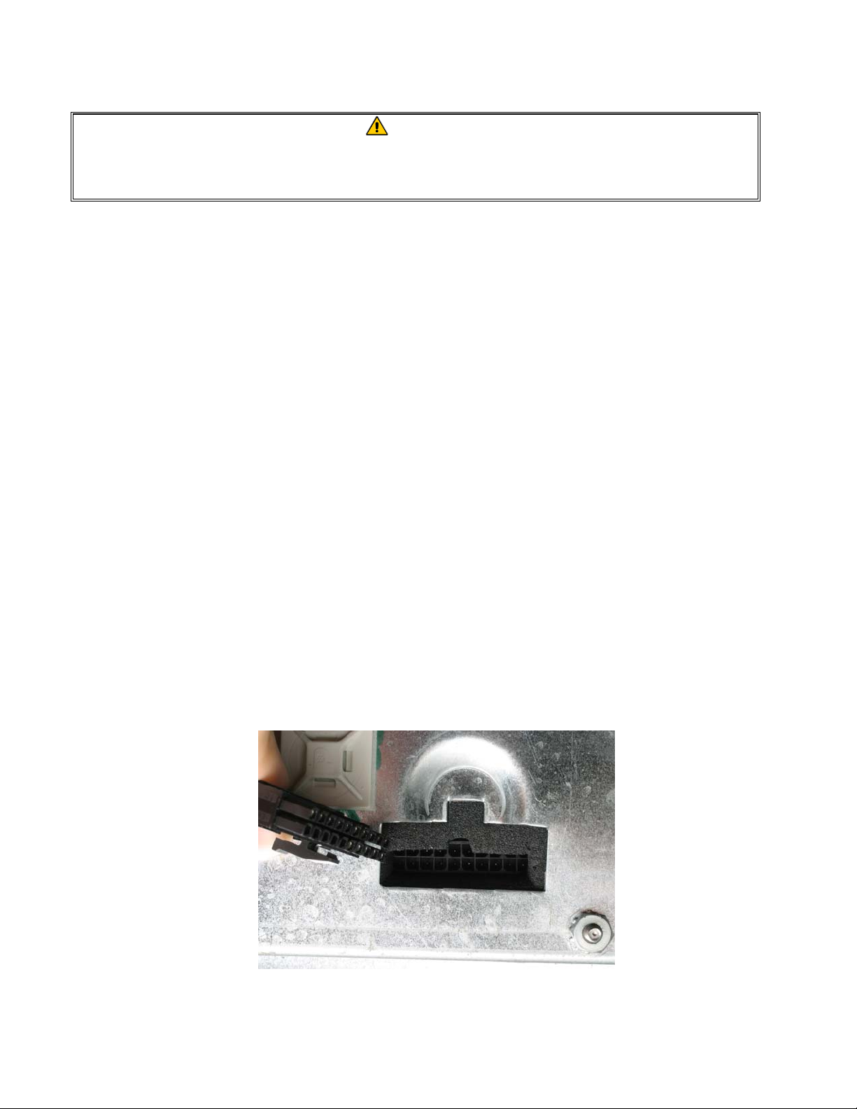
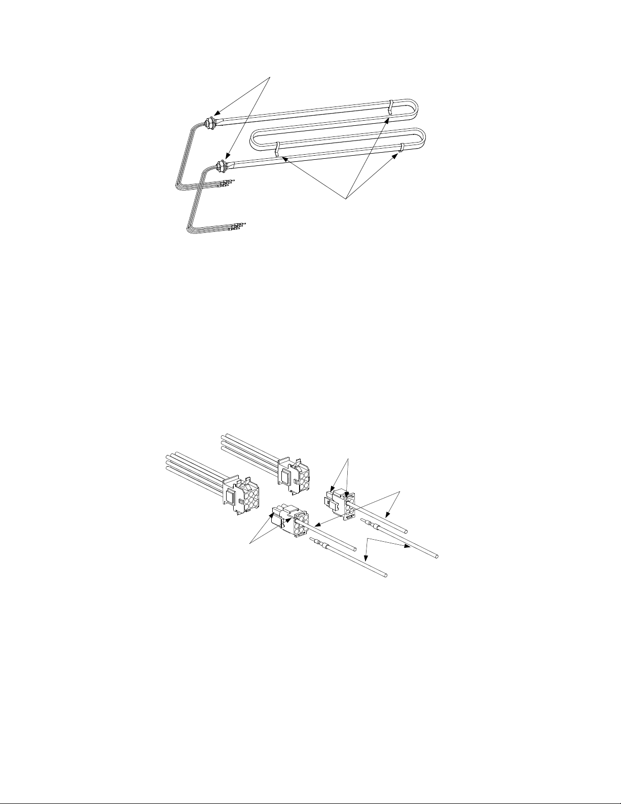
3. Unplug the element connector from the rear of the
component box. Depress the locking tabs on each side of
the connector and extend the connector to release the
element leads (see photo at right). Pull each of the leads out
of the connector, being careful not to damage the connector
in the process.
4. If the bundle of element leads is enclosed in a fiberglass
insulating sheath, cut the wire ties securing the sheath in
place, and remove and discard it; it is no longer required. If
replacing the left element (as viewed from the front of the
cooker), cut the metal wire ties that secure the high-limit
thermostat to the element, being careful not to bend the
thermostat in the process.
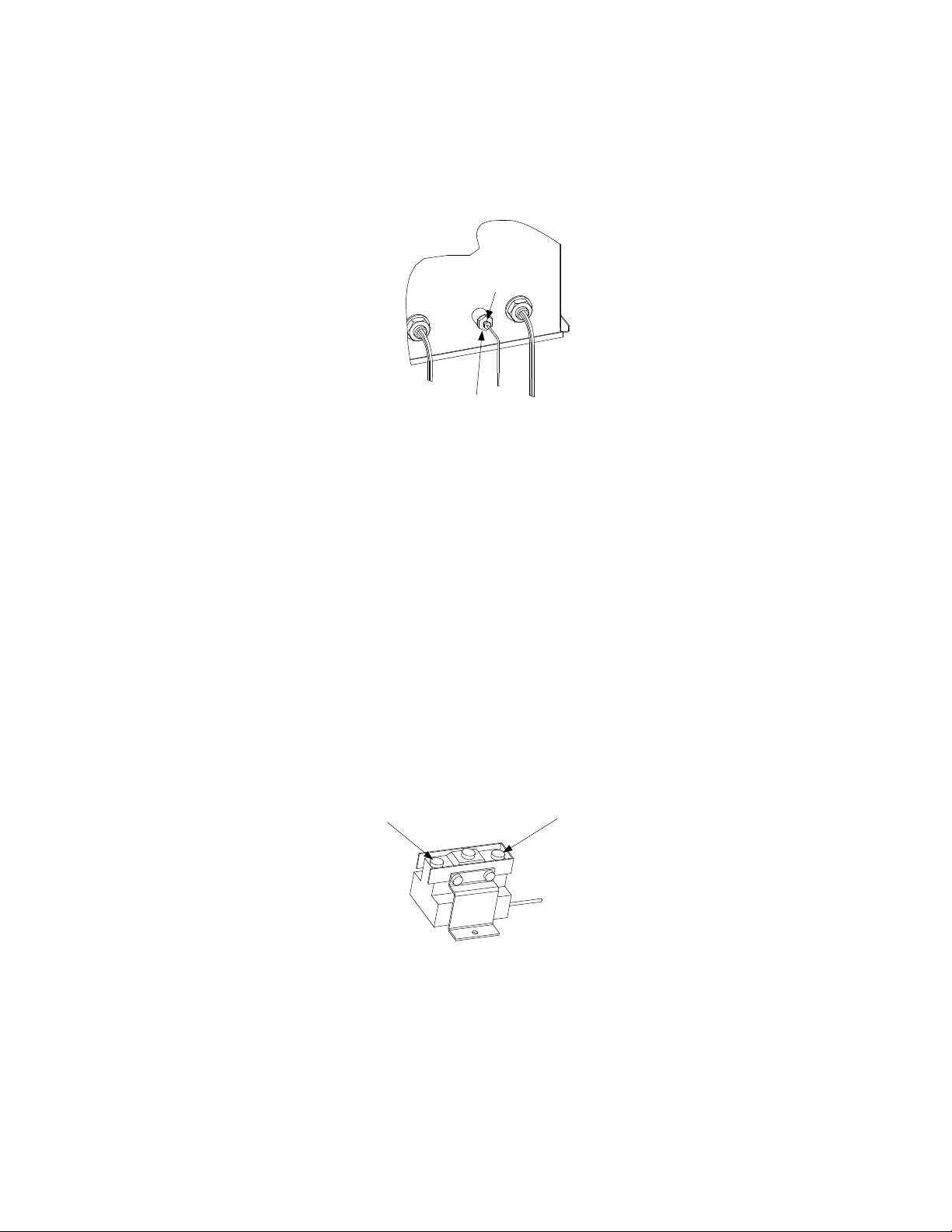
5. Remove the brass nuts that secure the element in the cookpot and lift the failed element from the
cookpot. Recover the Teflon washers from the failed element for use on the replacement.
1-3
Page 7
Remove these nuts to remove
element from cookpot.
Standoffs
6. Position the replacement element in the cookpot with the standoffs on the bottom of the cookpot.
Thread the element leads through the Teflon washers recovered from the failed element. Secure
the element in place with the nuts removed in Step 5.
7. If the left element (as viewed from the front of the cooker) was replaced, secure the high-limit
thermostat against the inside of the leg of the element with two metal wire ties.
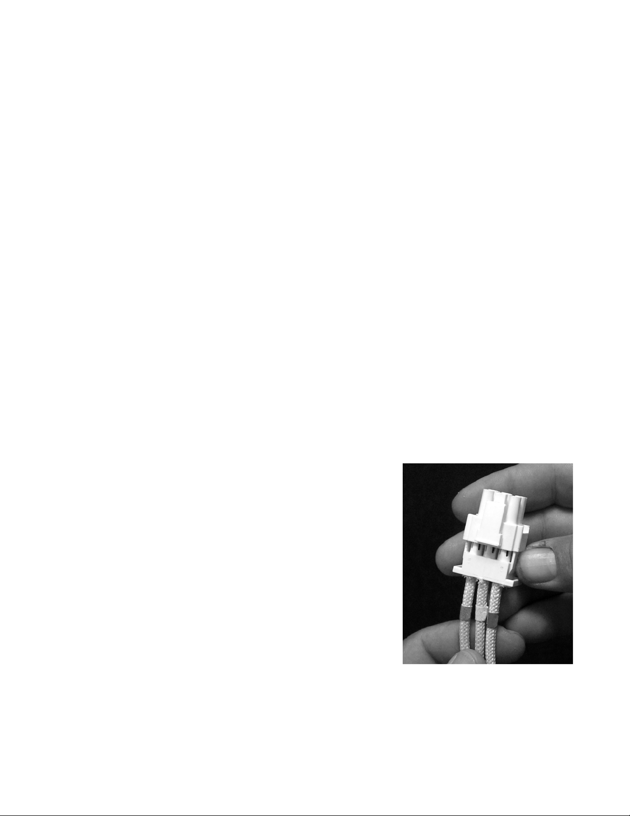
8. Insert the pins on the element leads into the element connector in accordance with the illustration
below. The insulation on the lead will be flush with the face of the plug when properly
positioned. When all leads are positioned correctly, close the connector and verify that the tabs
are locked in place. Each element lead is marked with a number that corresponds to the hole in
the connector into which it should be inserted. The right element (as viewed from the rear of the
unit) uses the 6-pin connector; the left element uses holes 1 through 6 of the 9-pin connector.
Note "D" pin and "pip"
indentifying Hole 1.
Lead 1
Lead 3
Note "D" pin and rib
indentifying Hole 1.
9. Bundle all six element leads together and secure with plastic wire ties close to the element and
connector, and in the middle.
10. Reverse Steps 1 through 3 to complete the procedure.
1.3.5 Replacing the High-Limit Thermostat
1. Drain the cookpot and disconnect the cooker from the electrical power supply. Disconnect the
unit from the water supply at the rear of the cooker. Remove the basket lift arms from the unit
and cut the metal wire ties securing the thermostat tube to the element.
1-4
Page 8
2. Reposition the cooker to allow clear access to the rear of the unit. Remove the upper and lower
basket lift panels.
3. At the rear of the cookpot, loosen the small compression nut, and then unscrew the large fitting
from the cookpot. Pull the thermostat tube out through the rear of the cookpot.
Loosen the small
compression nut first.
Unscrew the large fitting
only after loosening the
small compression nut.
4. Detach the high-limit thermostat leads (5C and 8C) from the thermostat. Remove the two screws
securing the thermostat to the mounting bracket and remove the thermostat assembly from the
cabinet. (NOTE: It is not necessary to remove the bracket.)
5. Loosen the small compression nut in the large fitting on the replacement thermostat so that the
large fitting will move freely on the capillary tube (the thin, flexible tube). Carefully insert the
replacement thermostat into the cookpot, being careful not to bend the thermostat tube. Position
the tube along the inside of the left leg of the element (as viewed from the front of the cooker)
and secure it in place with two metal wire ties. Apply thread sealer to the large fitting and screw
the fitting securely into the cookpot. When the large fitting is tight, pull gently on the capillary
tube to remove any slack, then screw the small compression nut into the large fitting and tighten.
6. Coil the capillary tube as necessary to achieve a neat installation and attach the terminal block to
the mounting bracket using the screws removed in Step 4. Connect thermostat lead 5C (black) to
the normally closed (NC) terminal and 8C (white) to the common (C) terminal.
Common (C) Terminal
(Note open side.)
Normally Closed (NC) Terminal
(Note closed side.)
7. Reverse Steps 1 and 2 to complete the procedure.
1.3.6 Replacing a Water-Level Sensor in 17kW Unit
Drain the cookpot and disconnect the cooker from the electrical power supply. Disconnect the
sensor lead from the sensor, remove the nuts securing the sensor in place, and remove the sensor.
Install the replacement sensor as illustrated below and reconnect the lead.
1-5
Page 9
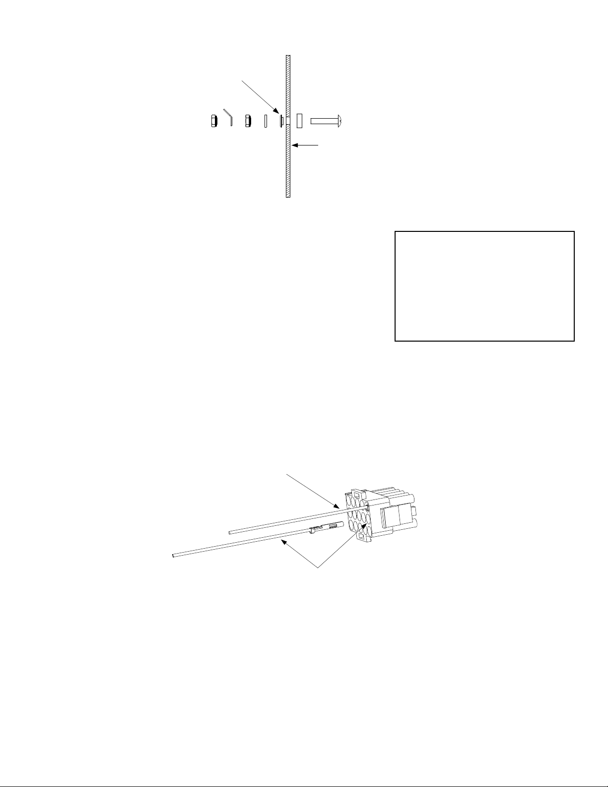
Insulator must seat in
hole before nut is
tightened.
Inside of cookpot.
1.3.7 Replacing the Temperature Probe
1. Drain the cookpot and disconnect the cooker from the electrical
power supply.
2. Remove the three screws along the upper edge of the control
panel and open the panel by allowing it to swing downward.
3. Disconnect the 15-pin connector from the rear of the computer
Testing Probe Resistance
A properly operating probe should
produce these resistances at these
temperatures:
552 Ω @ 60°F (16°C)
665 Ω @ 100°F (38°C)
1000 Ω @ 212°F (100°C)
and, using a pin pusher (such as Frymaster P/N 806-4855), push
out the temperature probe (red and white) leads from positions 13 and 14 on the connector.
4. Remove the temperature probe by unscrewing it from the front of the cookpot.
5. Apply thread sealer to the replacement probe and screw it securely into the cookpot.
6. Insert the red probe lead into position 13 of the 15-pin connector and the white lead into position
14. Pull gently on each lead to ensure it is firmly seated.
Insert red lead into position 13.
Insert white lead into position 14.
7. Reattach the 15-pin connector to the rear of the computer, close the control panel, and replace the
three screws removed in Step 2.
1.3.8 Replacing a Water Level Sensor or the Temperature Probe in 8 kW Unit
1. Drain the cookpot and disconnect the cooker from the electrical power supply.
2. Remove the basket lift arm by lifting it straight up from the lifter rod. Remove the probe cover
by lifting it straight up from the probe block.
1-6
Page 10
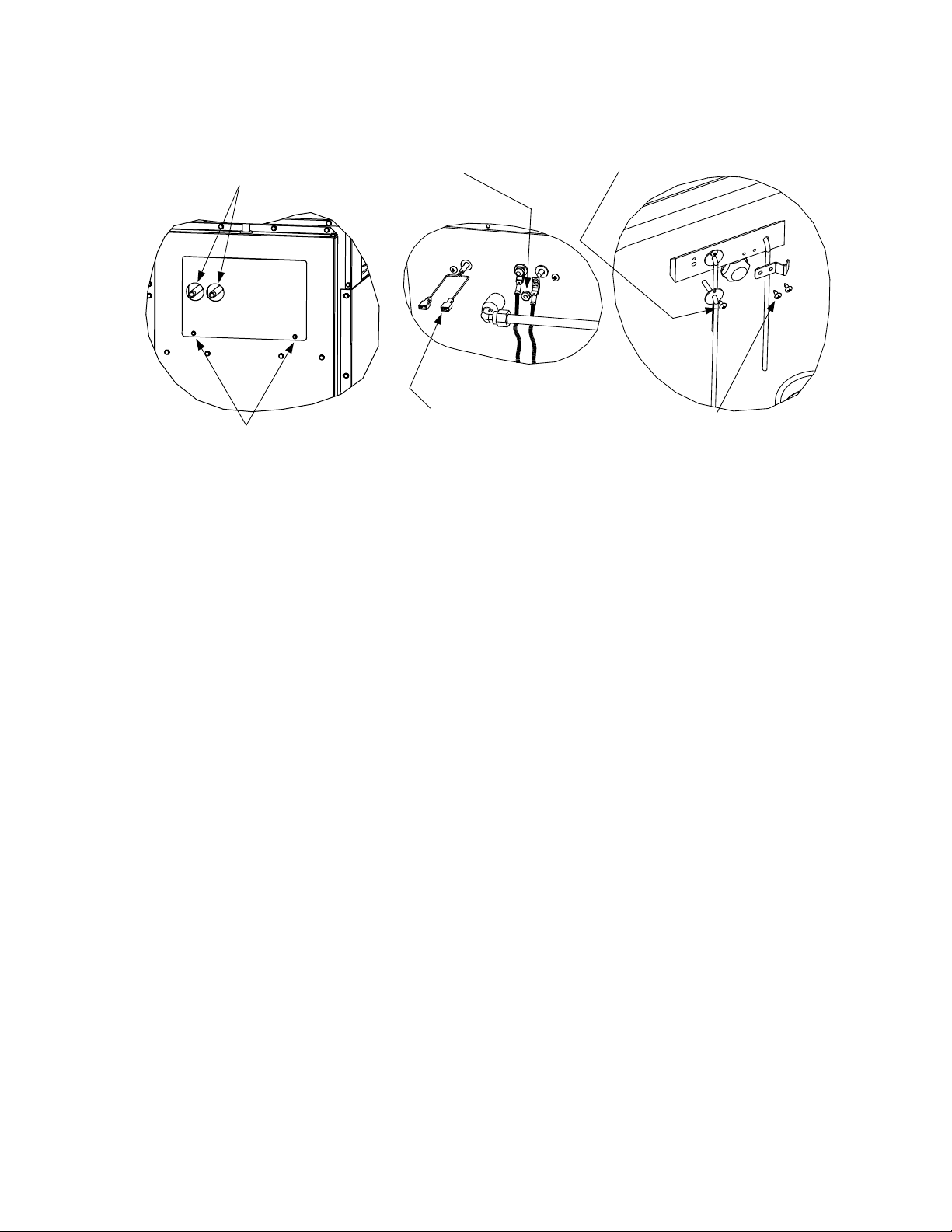
3. At the rear of the unit, remove the two screws securing the access panel and remove the panel.
Disconnect incoming
water lines from nipples.
Remove these two screws
and remove the access panel.
If replacing a water level sensor:
Remove its Keps nut to disconnect
the lead.
If replacing the temperature probe:
Mark the wiring harness leads and
disconnect the probe leads at the
push on connectors.
Remove the retaining screw from the sensor
flange and pull the sensor from the probe
block.
Remove the screws from the probe bracket
and push the probe out the back of the probe
block.
4. If replacing a water level sensor:
a. Disconnect the lead by removing the keps nut holding it in place.
b. Remove the screw in the sensor flange.
c. Carefully pull the failed sensor from the probe block and replace with the new sensor.
d. Reattach the lead and reverse Steps 1-3 to complete the procedure.
5. If replacing the probe:
a. Mark the wiring harness leads and disconnect them from the probe leads at the push-on
connectors.
b. Remove the two screws in the probe bracket.
c. Carefully pull the probe from the probe block and replace with the new probe.
d. Reattach the leads and reverse Steps 1-3 to complete the procedure.
1.3.9 Replacing the Pressure Regulator or Solenoid Valve
1. Drain the cookpot and disconnect the cooker from the electrical power supply. Turn off or
disconnect the water supply to the cooker.
2. Loosen the compression fittings on the water lines running to and from the regulator and remove
the regulator from the unit. (NOTE: If the cooker is equipped with the optional Autofill feature,
the solenoid valve is installed between the regulator and the cookpot. If that is the case,
disconnect the solenoid leads and remove both the regulator and solenoid valve from the unit.)
1-7
Page 11
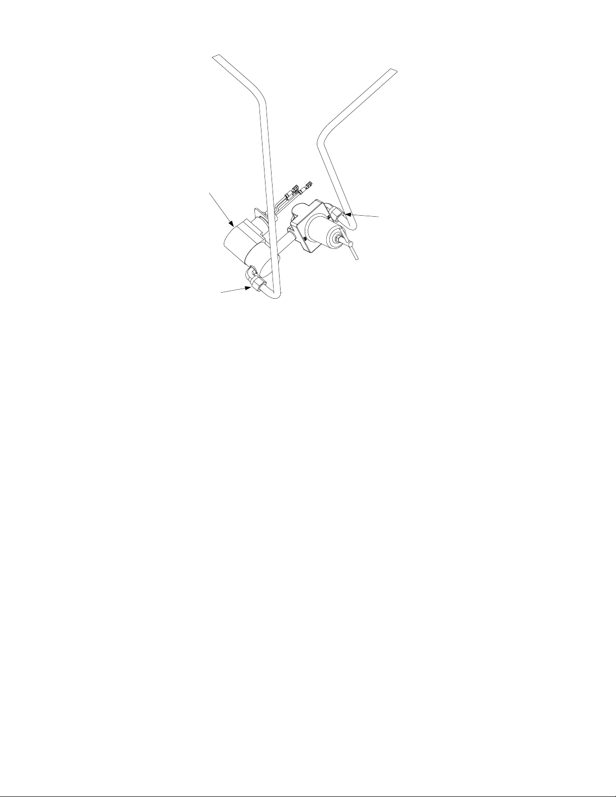
Optional Solenoid Valve
Compression Fitting
Regulator must be rotated
to clear drain plumbing.
Compression Fitting
3. If replacing the regulator, adjust the replacement regulator output pressure to not more than 40
PSI (28.15 kg/cm2) before installation in the cooker.
4. Recover the fittings from the failed component (regulator or solenoid valve) and install them on
the replacement, using thread sealer on all connections.
5. Reverse Steps 1 and 2 to complete the procedure, being sure to apply thread sealer to all
connections. NOTE: The regulator must be rotated approximately 45 degrees to clear the drain
plumbing (see illustration at Step 2).
1.3.10 Replacing the Water Faucet
1. Drain the cookpot and disconnect the cooker from the electrical power supply.
2. Turn off the water supply to the cooker and disconnect the incoming water lines where they
attach to the stubs at the rear of the cooker.
3. Remove the two screws securing the access panel in place and remove the panel.
4. Disconnect the water supply line at the compression fitting where it attaches to the water inlet
manifold. Remove the screws from the faucet mounting plate and lift the faucet assembly from
the unit.
1-8
Page 12
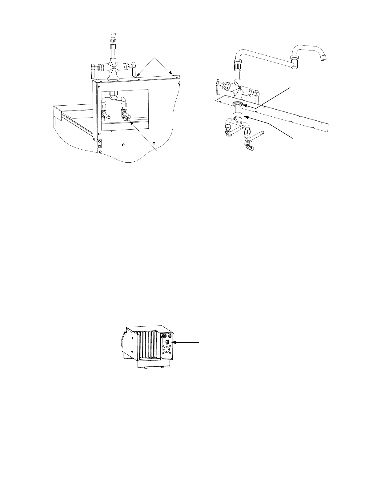
Remove screws to remove the
faucet mounting plate.
Remove this nut to separate the
faucet from the mounting plate.
Loosen this nut to separate
the faucet from the water
Disconnect this
compression fitting.
inlet manifold.
5. Separate the faucet from the water inlet manifold and mounting plate as shown in the illustration
at Step 4.
6. Reverse Steps 1-5 to complete the procedure.
1.3.11 Replacing a Basket Lift Motor or Microswitch
1. Disconnect the cooker from the electrical power supply.
2. If rigid water connections have been used, disconnect the cooker from the incoming water
supply.
3. Remove the basket lift arms from the lifter rods and then reposition the cooker to gain access to
the rear. Remove the upper and lower basket lift rear panels.
4. Unplug the basket lift wiring harness from the lower 6-pin connector on the component box. (To
do this, you must reach around behind the component box from the front of the cooker.)
Disconnect basket lift wiring
harness from this connector.
5. Disconnect the basket lift link from the lifter cam (bell crank) assemblies one at a time. When
the link is disconnected from a cam, slip the corresponding lifter rod down and out of the
assembly (see illustration).
1-9
Page 13

Lifter Rods
Link
Disconnect the basket lift link from
the lifter cams and slip the lifter rods
down and out of the assembly.
6. Remove the four bolts securing the motor mount to the frame, then remove the motor and mount
assembly from the unit. NOTE: It is possible to replace a motor or the microswitch without
removing the motor and mount assembly, but it is much more difficult.
7. Dismount the motor or microswitch as shown below and install the replacement.
NOTE:
The right motor dismounts
in the same way as the left.
Loosen setscrew in bottom
8. Reverse Steps 1-7 to complete the procedure.
1.3.12 Replacing the Cookpot or Rinse Tank
1. Remove the faucet assembly from the
cooker in accordance with Steps 1-4 of
Section 1.3.8.
2. Remove the screws that secure each of the
rear corners of the backsplash assembly (see
illustration at right). NOTE: To access the
screw in the lower right corner (as viewed
from the rear) remove the upper basket lift
panel.
of cam (bell crank).
Remove these four screws.
1-10
Page 14

3. Remove the screws along the top edge of
the control panel and open the panel by
swinging it downward. Disconnect the
connector from the rear of the computer,
and then lift the control panel out of the
control panel frame.
4. Remove the screws that secure the
backsplash sides to the cabinet sides then
remove the four screws that secure the
topcap to the cabinet. Remove the nut and
washer securing the basket support rod to
the topcap by reaching up through the
Remove these
screws (on both
sides) to remove
backsplash and
topcap.
control panel frame. Conversely, the
backsplash and topcap, with the basket
support rod still attached, can be lifted up
Remove these screws to
dismount the control panel.
and off the cooker as one unit.
5. Remove the screws attaching the standoff
brackets to the cookpot or rinse tank.
Remove these screws to release
the pots from the standoff brackets.
6. If removing the cookpot, unplug the element
wiring harnesses from the rear of the
contactor box. Disconnect the high-limit
thermostat leads and the water-level sensor
leads. Using a pin-pusher (such as
Frymaster P/N 806-4855), disconnect the
temperature probe leads from the 15-pin
connector.
7. Disconnect the union joining the cookpot
and rinse tank drain piping together.
8. With an assistant, lift the cookpot or rinse
tank straight up and out of the cabinet.
9. Invert the cookpot or rinse tank on a suitable work surface and remove the salvageable
components (e.g., elements, thermostats, drain plumbing, etc.). Install the recovered components
on the replacement cookpot or rinse tank, using thread sealer on all connections.
10. Reverse Steps 1 through 8 to complete the procedure.
1-11
Page 15

1.4 Troubleshooting
NOTE: The 24VAC power to the electronic components of this system is controlled by the master
ON/OFF switch located on the front of the contactor box. If this switch is in the OFF position, none
of the system components will function.
DANGER
The master ON/OFF switch does not disconnect this equipment from the electrical power
source! Line voltage is supplied to the transformer and to the basket lift motors as long as the unit
is plugged in.
Problems with this equipment may be grouped into five broad categories:
1. Failure or malfunction of a 24VAC power-supply system component.
2. Failure or malfunction of the computer.
3. Failure or malfunction of an Autofill/AutoSkim system component.
4. Failure or malfunction of a water heating system component.
5. Failure or malfunction of a basket lift system component.
Sections 1.4.1 through 1.4.5 briefly explain the functioning of each of the systems mentioned above.
Section 1.4.6 contains troubleshooting guides that provide systematic procedures to isolate and
identify the specific source of a problem. A wiring diagram is located at the end of the chapter.
1.4.1 How the Power-Suppl y System Works
Line voltage is supplied to the system via a power cord that is plugged or hard-wired into the store’s
electrical service. The power cord is attached to a three-lug delta-power terminal block. One set of
wires delivers line voltage from the load side of the block to Terminal 1 of each of the solid-state
relays. A second set of wires delivers line voltage through a pair of fuses to the 24VAC transformer
and to the basket lift relay. Line voltage for one side of the basket lift motor circuit is tapped from a
“piggy-back” terminal on the line side of the transformer. Line voltage for the other side of the
circuit is supplied via the basket lift relay. 24VAC is supplied to the equipment by placing the master
ON/OFF switch in the ON position, which grounds the transformer.
1.4.2 How the Computer Works
The SMS III computer provides the interface between the operator and the system components. The
computer is powered by 24VAC supplied through Pins 1 (hot) and 2 (ground) of the 15-pin wiring
harness. Internal circuitry senses the water level, water temperature, and element temperature.
Depending upon the conditions sensed, the computer energizes or de-energizes the solenoid valve to
control water level and the heating elements to control water temperature. The computer also
controls the lowering and raising of the basket lift, and activates an audible alarm, indicating a
cooking cycle is complete. A rectifier in the computer coverts 24VAC to the 24VDC required by the
basket lift relay and the solid-state heating relays. The computer signals for heat via Pin 4, grounds
the solenoid valve via Pin 6, and senses water level via pins 7 (low) and 9 (full). The temperature
probe connects to Pins 13 and 14. The basket lift relay connects to pins 10 and 12. The sound device
connects to pin 11.
1-12
Page 16

1.4.3 How the Autofill/AutoSkim System Works
The heart of the automatic filling (Autofill) system is a normally closed solenoid valve that opens
when 24VAC is applied.
The ground for the solenoid is supplied (via pin 6 of the computer wiring harness) so long as the
upper water-level sensor is not in contact with the water in the cookpot. When the water in the
cookpot reaches the upper water-level sensor, the sensor is grounded. This causes the computer to
break the solenoid ground, closing the valve. Starch or lime build-up on the upper water-level
sensor may keep a ground from forming, therefore always make sure the sensor is clean and its lead
(pin 9 of the computer wiring harness) is firmly connected. Also, in order for the ground to form,
there must be some mineral content in the water (pure water is non-conductive). Consequently, the
units will not operate with distilled water. If distilled, highly filtered, or purified water is used, add
⅛-cup of baking soda to the water each time the cookpot is emptied and refilled.
When the AutoSkim feature is activated by pressing the skim switch on the computer, a logic circuit
in the computer automatically opens the solenoid valve for three seconds every minute until the
switch is again pressed. If the Autofill feature is working properly, failure of the AutoSkim feature
will be due to a malfunctioning computer and not the solenoid valve. (Proper operation of the
Autofill feature can be determined by draining water from the cookpot until the water level is below
the upper water-level sensor. If the solenoid valve opens and then closes when the water in the
cookpot again reaches the upper water-level sensor, the Autofill feature is working properly.)
1.4.4 How the Water Heating System Works
To prevent energizing the heating elements when there is no water in the cookpot, these units are
equipped with a low-water-level sensor. This sensor must be grounded by contact with water in the
cookpot before the control circuitry will apply power to the elements. Starch or lime build-up on the
low-water-level sensor may keep the ground from forming, therefore always make sure the sensor is
clean and its lead (pin 7 of the computer wiring harness) is firmly connected. In order for the ground
to form, there must be some mineral content in the water (pure water is non-conductive).
Consequently, the units will not operate with distilled water. If distilled, highly filtered, or purified
water is used, add ⅛-cup of baking soda to the water each time the cookpot is emptied and refilled.
In addition to the low-water-level sensor discussed above, the water heating system has six more
parts: the high-limit thermostat, the temperature probe, the contactor, the element, a group of three
solid-state relays, and the computer.
The high-limit thermostat functions as a normally closed switch. If the water in the cookpot falls
below the low-water-level sensor but the sensor remains grounded (for whatever reason), the highlimit switch will open when the element temperature reaches 400ºF ±15 (204ºC ± 9). This cuts
power to the contactor coil and thus to the element.
The temperature probe is used only when the unit is in the simmer mode. When the operator
selects the simmer mode, logic circuits in the computer monitor the temperature of the water and
cycle power to the element to maintain the the programmed temperature.
The contactor is the terminal block to which the element leads are connected and where contact is
made between the leads and the line voltage. Built into the contactor is a 24VAC coil that energizes
1-13
Page 17

when the master ON/OFF switch is placed in the ON position. When it energizes, contact is made
between the incoming line voltage and the element leads, and line voltage is supplied to one side of
the element circuit. The solid-state relays control the supply of line voltage to the other side of the
element circuit. The relays are closed when the computer is calling for heat and open when it is not.
The element is a resistive heating device. That is, when voltage is applied to the element, the
element gets very hot due to its resistance to current flow through it. The heat generated is
transferred directly to the water.
The computer is the interface between the operator and the other components of the equipment. In
the water heating system, its function is to control the application of line voltage to the heating
element via the solid-state relays.
When in the Simmer Mode, the signal from the computer is continuous, the solid-state relays are
continuously closed, and line voltage is applied to the elements until the simmer setpoint
(195ºF/90.6ºC) is reached.
When in the Boil Mode, the signal from the computer is continuous for approximately the first 40
seconds, then changes to a series of on-off pulses of equal duration. The solid-state relays close
and open in response to the signal from the computer, and line voltage is applied to the elements
accordingly. (The pulsing of the line voltage to the elements prevents the water in the cookpot
from reaching a vigorous, roiling boil. This, in turn, minimizes the formation of starch foam. An
added benefit of the pulsing is reduced electrical power consumption.)
1.4.5 How the Basket Lift System Works
When the Start switch is pressed to start the cooking cycle, logic circuits in the computer activate the
basket lift motors, lowering the basket into the cookpot. As the motors drive the basket lift arms
down, a cam attached to the left motor eventually loses contact with a roller-activated microswitch
and power to the motors is cut. When the computer times out, logic circuits reverse the switch
positions so that the motor circuit is again completed and the motors are restarted, raising the basket
from the cookpot. At the fully raised position, the cam again makes contact with the microswitch,
cutting power to the motors and stopping the lift in the up position.
1-14
Page 18

1.4.6 Technician Troubleshooting Guides
Symptom Potential Cause Diagnosis
Master switch not on
Unit not plugged in.
Failed 24-volt transformer.
Failed or loose wiring.
Computer doesn’t activate
Unit not connected to
water supply.
Dirty or failed water
Cook pot fails to fill
Unit fails to heat
sensor.
Failed water solenoid.
Failed controller.
Unit is not
Hi-limit is open.
Probe resistance
Solid state relay
Element failure.
plugged in or
breaker is open.
is out of tolerance.
failure.
Turn switch on.
Plug unit in.
Test input and output
voltage from transformer.
Check fuses in
transformer circuit; check
continuity of power switch
in on position; check for
24VAC on pins 1 and 2 of
the computer wiring
harness.
Connect to water supply.
Clean water sensors; add
baking soda to cookpot
water.
Check for 24VAC in water
solenoid circuit.
Plug unit in; check
breaker.
Check continuity of hi-
limit. Replace if open.
Check probe resistance at
pins 13 and 14 of the 15pin computer plug. See
Testing Probe on page 1-
6.
Check probe resistance
between each pin and
ground. Should be 2 mega
Ohms or greater.
With the computer calling
for heat, check for input
voltage (5-10VDC) on the
solid state relays and line
voltage on the output
terminals. Zero input
voltage suggests a failed
relay.
With the computer not
calling for heat, check for
input voltage (5-10VDC)
and line voltage on the
output terminal. No line
voltage suggests a failed
relay.
Ohm out element on pins
1- 6; 2-5; and 3-4.
Resistance should be 15
Ohms ±3.
1-15
Page 19

Symptom Potential Cause Diagnosis
Basket lift fails to work
Failed fuse
Failed computer.
Failed or loose wiring.
Failed basket lift relay.
Failed motor.
Replace 15-amp fuse
With basket lift up, check
for 27-33VDC at pin 10 of
15-pin plug. Zero volts if
basket lift is down. No
voltage: computer has
failed.
With basket lift up, check
for 27-33VDC (Zero
voltage if basket lift is
down) at basket lift relay
terminal. None or
improper voltage: check
for loose or corroded
wiring.
With basket lift up, is line
voltage present at the NC
(lower) terminal of basket
lift microswitch (middle
terminal with basket lift
down)? This suggests a
bad relay.
With basket lift up, is line
voltage present at the
common position of the
microswitch. This
suggests a failed motor.
1-16
Page 20

2.1 Parts List
ACCESSORIES
1
2
3
4
7
8
ITEM PART # COMPONENT
1 823-1910 Cooking Basket
* 823-7384 Basket, bulk
* 823-6290 Basket, wash
2 823-2936 Starch Diverter
* 803-0200 Rack, 12 portion
* 803-0238 Basket, round 5.5 x 8.5
* 803-0018 Cup, pasta portion (beige)
3 803-0332 Basket Support Rack
* 210-5068 Pan Insert
4 910-7540 Cookpot/Rinse Tank Top Connecting Strip
5 823-2938 Rinse Basket
6 826-0900 Chain Restraint Kit
7 826-1117 Caster without Brake, 5-Inch (includes mounting hardware)
8 826-1118 Caster with Brake, 5-Inch (includes mounting hardware)
5
6
2-1
Page 21

BASKET LIFT COMPONENTS
36
3
35
5
8
33
34
31
32
38
37
29
30
28
27
22
39
21
26
23 24 25
20
19
6
1
2
7
9
10
11
12
13
4
18
14
15
16
17
2-2
Page 22

ITEM PART # COMPONENT
1 823-7061 Arms, Basket Lift, 17SMS
823-7604 Arms, Basket Lift, 8SMS
2 910-7420 Top, Basket Lift Enclosure, 17 SMS
910-1641 Top, Basket Lift Enclosure, 8SMS
3 222-3763 Side, Basket Lift Enclosure Right
4 221-3763 Side, Basket Lift Enclosure Left
5 900-7421 Support, Basket Lift Rod Bushing
6 826-1363 Screw, 8-32 x ½-inch Slotted Truss Head (Pkg of 25)
7 902-1927 Bracket, Left Basket Lift Roller
8 901-1927 Bracket, Right Basket Lift Roller
9 809-0247 Nut, 8-32 Hex Keps
10 809-0508 Bolt, ¼ -20 x 1 ¼-inch Hex Head SS
11 810-0194 Roller, Basket Lift
12 809-0047 Nut, ¼-20 SS Hex Cap
13 809-0082 Ring, ¾-inch Truarc
14 810-0045 Bushing, Basket Lift Rod
15 807-0108 Motor, 240VAC Basket Lift
16 900-7416 Mount, Basket Lift Motor
17 809-0113 Screw, 8-32 x 1 ½-inch Slotted Truss Head
18 809-0050 Nut, 8-32 Hex
19 812-0138 Insulation, Motor Mount (Fishpaper)
20 807-0240 Microswitch
21 809-0097 Screw, 6-32 x 1-inch Slotted Truss Head
22 826-1358 Nut, 6-32 Hex (Pkg of 25)
23 810-0052 Cam (Bellcrank), Basket Lift
24 809-0194 Washer, 5/16-inch SAE Flat
25 809-0196 Washer, ⅜-inch SAE Flat
26 809-0063 Nut, Jam 3/8-16 Hex
27 826-1381 Washer, ½-inch ID x ⅞-inch OD Nylatron Flat (Pkg of 10)
28 910-4525 Bar (Link), Basket Lift Synchronizing
29 809-0155 Screw, 5/16-18 x ⅝-inch Leveling
30 826-1370 Screw, ¼-20 x 1 ¼-inch Slotted Round Head (Pkg of 10)
31 809-0076 Nut, ¼-20 x ¾-inch Expansion
32 920-6076 Link, Basket Lift
33 810-0170 Pin, ¼-inch x ⅝-inch Spring Dowel
34 810-0192 Rod, 19 ⅝-inch Basket Lift
35 809-0127 Screw, ¼-20 x ½-inch Slotted Round Head
36 900-7418 Panel, Upper Basket Lift Rear
37 220-3761 Panel, Lower Basket Lift Rear
38 807-0124 Bushing, Heyco
39 810-0220 Spacer, Tubular, .493-inch OD
2-3
Page 23

17 SMS CABINETRY
10
9
13
12
5
7
6
4
14
15
16
17
11
8
2
3
1
12
20
31
25
30
22
27
28
29
Components
Showing Attached
Detail of Backsplash
33
32
26
18
19
21
24
23
34
ITEM PART # COMPONENT
1 210-0815 Channel, Front or Rear Base
* 806-5209 Leg Pad Assembly (on bottom of Item 1, for mounting casters)
2 210-0816 Channel, Side Base
3 900-7198 Post, Door
4 900-1552 Gusset (Corner Brace)
5 900-7389 Brace, Top Rear
6 900-7390 Brace, Top Front
7 900-7391 Divider, Cabinet
8 Side, Left or Right Cabinet, 17SMS
910-7377 Stainless Steel
2-4
Page 24

ITEM PART # COMPONENT
900-7377 Cold Rolled Steel (Painted)
9 210-8305 Back, Cabinet, 17SMS
10 900-1750 Panel, Plumbing Access
11 900-4645 Shield, Heat
12 210-0007 Backsplash
13 210-0215 Plate, Faucet Mounting
14 810-1838 Rod, Basket Pivot
15 809-0200 Washer, ½-inch Flat
17 824-0801 Topcap, 17EC1CS, Fazoli’s
* 824-0434 Topcap, 17E1, no rinse tank
18 806-5487 Frame, Control Panel
19 823-2946 Panel, Control
21 106-0590 Door Assembly, Left or Right (does not include handle or hinges)
22 810-1508 Hinge, Universal Door
23 210-0817 Shield, Left Moisture
24 210-0818 Shield, Right Moisture
25 910-4831 Bracket, Basket Lift Roller
27 810-0374 Spacer, Basket Lift Roller Tubular
28 810-0194 Roller, Basket Lift
29 809-0190 Washer, ¼-inch SS Flat
30 809-0047 Nut, ¼-20 Hex Head Cap
31 809-0127 Screw, ¼-20 x ½-inch Slotted Round Head
32 810-2229 Hanger, basket wire
33 809-0171PK Thumbscrew, Basket Hanger (20)
34 230-4963 Handle, door
Fastners
ITEM PART # COMPONENT
* 826-1371 Screw, #8 x ½-inch Hex Head (access panel screw)
* 809-0740 Screw, #10 x ½-inch Phillips Truss Head (faucet plate and topcap screw)
16 809-0063 Nut, ⅜-16 Jam
20 826-1351 Retainer, ¼-20 Nut (Nutsert) (Pkg of 10)
* 809-0266 Screw, #10 x ½-inch Phillips Truss Head (door panel and handle screw)
26 809-0508 Bolt, ¼-20 x 1 ¼-inch Hex Head
29 809-0190 Washer, ¼-inch SS Flat
30 809-0047 Nut, ¼-20 Hex Head Cap
31 809-0127 Screw, ¼-20 x ½-inch Slotted Round Head
* Not illustrated.
2-5
Page 25

8SMS Cabinet Components
1
2
3
4
6
7
823-7382 8C/8BC Fluecap
5
823-7393 8SMS Cook/Rinse
8
823-7394 8SMS Rinse/Cook
9
10
824-2088 8C/8BC
824-2089 8SMS
2-6
Page 26

Item Part # Component
1 231-5452 Side, left, stainless
221-5452 Side, left, cold rolled
2 220-5455 Door post
3 220-5826 Divider
4 232-5452 Side, right, stainless
222-5452 Side, right, cold rolled
* 230-5733 Back
* 220-6246 Single cabinet back
5 108-0577 Door, SMS
* 106-4067 Door pin assembly
* 810-0275 Spring, door pin
* 220-5760 Door, liner
* 230-4963 Handle
* 810-1105 Door, magnet
6 823-7382 8C/8BC flue cap
7 823-7394 8SMS Rinse/Cook flue cap
8 824-2088 8C/8BC top cap
9 824-2089 8SMS top cap
1
Controllers
Item Part # Component
1 106-0384 Computer, 17SMS, Fazoli’s
106-0385 Computer, 17SMS
106-2926 Computer, 17SMS, Noodles
108-1131 Computer, 8SMS, with skim
2-7
Page 27

17 SMS COOKPOT, RINSE
TANK, AND DRAIN
COMPONENTS
11
10
9
8
26
27
30
29
Mounting Hardware
Detail of High-Limit Thermostat
25
2
1
24
23
22
19 20 21
18
28
12
13
14
15 16 17
7
5 6
3
4
2-8
Page 28

ITEM PART # COMPONENT
1 106-0461 Cookpot Assembly (for 17EMCS (McDonald’s), use 823-3827SP)
2 106-0543 Rinse Tank Assembly
3 806-7552SP Water level sensor assembly
4 900-5045 Retainer, Cookpot Front Insulation
* 816-0152 Insulation, Cookpot Front (behind Item 4)
5 900-1762 Retainer, Insulation
6 826-1376 Nut, 10-32 Hex Head Keps (Pkg of 10)
7 807-3333 Probe, Temperature
8 210-0681 Guard, Temperature Probe
9 826-1601 Thermostat, High-Limit
10 807-3814 Element, 208V 8.625kW (for 230V, use 807-3815; for 240V, use 807-3816)
11 810-0976 Nozzle
12 813-0451 Nipple, 1 ¼-inch NPT x 12-inch Chromed Brass
13 813-0453 Nut, 1 ¼-inch NPT Chromed Stainless Steel Slip
14 813-0148 Nipple, 1 ¼-inch NPT x 6 ¼-inch NPT
15 813-0070 Elbow, 1 ¼-inch NPT 90º
16 813-0400 Nipple, 1 ¼-inch NPT x 2-inch
* 813-0391 Nipple, 1 ¼-inch NPT Close (connects cookpot drain valve and Item 19)
17 813-0394 Tee, 1 ¼-inch NPT
18 813-0146 Nipple, 1 ¼-inch NPT x 4 ¼-inch
19 813-0518 Nipple, 1 ¼-inch NPT x 4-inch
20 813-0395 Union, 1 ¼-inch NPT
21 813-0144 Nipple, 1 ¼-inch NPT x 3 ¾-inch
22 813-0554 Nipple, 1 ¼-inch NPT x 7-inch
23 814-0047 Sleeve, Red Drain Valve Handle
24 910-9527 Handle, Drain Valve
25 810-1825 Valve, 1 ¼-inch NPT Drain
26 823-2022 Strainer
27 910-2042 Clamp, Element
28 910-5214 Support, Element
29 910-2097 Bracket, High-Limit
30 809-0518 Screw, #8 X ⅜-inch S/S Hex Washer Slot Head
* 809-0204 Washer, Teflon (fits between Item 10 and inside face of Cookpot)
* 809-0063 Nut, ⅜-16 Jam (secures Drain Valve Handle to Drain Valve)
* Not illustrated.
2-9
Page 29

8 SMS COOKPOT, RINSE
TANK, AND DRAIN
COMPONENTS
16
15
14
13
17
12
11
10
9
4
2
3
5
6
1
18
21
19
20
8
7
2-10
Page 30

ITEM PART # COMPONENT
1 823-7044 Cookpot assembly
2 210-0151 Handle, s/s drain valve
3 810-1825 Valve, SS 1 1/4 x 1 1/4 drain
4 814-0047 Sleeve, handle vlv red
5 8130391 Nppl, 1 1/4NPT x close bm
6 813-0394 Tee, 1 1/4NPT bm
7 813-0451 Nppl,1 1/4 x 12.00 chrome/brs
8 813-0070 Elbow, 1 1/4 NPT 90deg bm
9 8130-146 Nppl,1 1/4npt x 4.25 bm
10 813-0453 Nut,slip 1 1/4NPS chrome stl
11 813-0451 Nppl,1 1/4 x 12.00 chrome/brs
12 826-1601 Thermostat, high limit
13 813-0302 Elbow,mle 3/8tbe to 1/4npt brs
14 826-1798 Element,240v 8000 watts 3p
15 810-0713 Nozzle,spray
16 806-9366 Block assy w/auto probe
17 823-7045 Rinse tank assembly
18 210-0151 Handle, s/s drain valve
19 814-0047 Sleeve, handle vlv red
20 813-0391 Nppl, 1 1/4NPT x close bm
21 810-1825 Valve, SS 1 1/4 x 1 1/4 drain
2-11
Page 31

8
7
17 SMS ELECTRONICS
9
17 18
6
15 16
10
14
4
5
11
12
3
2
13
4
1
1
2
3
4
5
6
7
8
9
1
2
3
4
5
6
7
8
9
10
11
12
13
14
15
1H BLK
2H BLK
3H BLK
4H BLK
5H BLK
6H BLK
1C BLK
2C BLK
3C BLK
4C BLK
5C BLK
6C BLK
7C BLU
8C WHT
9C BLU
10C
BLK
11C BLK
12C
BLK
15C WHT
106-0157
7
1
2
3
4
5
6
7
8
9
10
11
12
13
14
15
106-0144
8
106-0156
1
2
3
4
5
106-0160
6
51C WHT
52C WHT
53C BLK
1
2
3
4
5
6
1H BLK
2H BLK
3H BLK
4H BLK
5H BLK
6H BLK
Computer harness
2-12
Page 32

ITEM PART # COMPONENT
* 824-0856 Starch Shield (mounts to back of control panel to protect computer)
1 807-0922 Holder, fuse
2 807-0680 Transformer, 208-240VAC/24VAC 50/60Hz 43VA
3 810-1202 Contactor, 3 Pole 600VAC 40 Amp
4 106-7574 Harness, 15-pin control box
5 807-2082 Switch, Non-Illuminated Rocker
6 807-3996 Relay, 75 Amp 280V SPST-NO Solid State
7 106-0157 Harness, 9-pin harness, Fazoli’s
8 106-0156 Harness, 6-pin
9 106-7573 Harness, 6-pin
10 807-2464 Power block, Delta
11 807-1396 Relay, 24V, SPDT
12 807-2279 Fuse, 15 amp
13 106-7575 Contactor box assembly
14 806-3660 Sound device
15 807-2136 Connector, 6-pin, female
16 807-2138 Connector, 9-pin, female
17 807-0804 Connector, 15-pin, male
18 807-0875 Connector, 15-pin, female
* 900-5445 Cover, front, contactor box
* 900-5895 Cover, top, contactor box
* 900-8239 Contactor box
* Not illustrated.
2-13
Page 33

8SMS Electronics
2
1
5
8
9
10
3
6
11
ITEM PART # COMPONENT
1 807-4036
2 807-2284
3 807-4483
4 807-1292
5 807-0680
6 807-0070
7 807-1393
8 807-0922
9 807-2279
10 807-1396
11
*
*
220-4211
823-6293
900-7853
Switch, dpst rckr
Contactor,50 amp mech 24v coil
Fitting,pastic conduit 3/4x90d
Fitting,conduit plastic
Transformer primary 208/240v
Terminal ground lug
Valve,solenoid 2 way 1/4npt
Holder screw type Buss fuse
Fuse, 15 amp
Relay 24 dc spdt
Bracket,strain relief sms
Box, contactor 8sms
Cover, contactor box
4
7
2-14
Page 34

Water supply system components
14
11
13
10
1
4
7 8
6
2
3
9
4
5
ITEM PART # COMPONENT
1 810-0907 Elbow, ⅜-inch NPT Compression
2 910-2513 Tubing, Solenoid Valve to Cookpot ⅜-inch Stainless Steel
3 806-5565 Valve Assembly, 24VAC 60Hz Solenoid
4 813-0302 Elbow, ⅜-inch Tube to ¼-inch NPT 90º Brass Male
5 813-0472 Nipple, ¼-inch NPT x 2.5-inch Brass
6 900-1905 Mount, Solenoid Valve
7 813-0022 Nipple, ½-inch NPT x Close
8 809-0454 Nut, ½-inch Conduit
9 810-1208 Valve, Pressure Regulator
10 900-1898 Tube, ⅜-inch Water Line
11 813-0449 Tee, ¼-inch NPT Brass
12 813-0448 Elbow, ¼-inch NPT 90º Brass
13 813-0473 Nipple, ¼-inch NPT x 4-inch Brass
14 813-0412 Faucet, Double Jointed Pantry
* 826-1132 Kit, Faucet Repair (contains two valve assemblies)
* Not illustrated.
12
2-15
Page 35

2.2 Wiring Diagram 17E1
2.3 Wiring Diagrams (17SMS 220V/380V)
2-16
Page 36

2-17
Page 37

2.4 Wiring Diagrams (8SMS)
2-18
Page 38

Shipping Address: 8700 Line Avenue, Shreveport, Louisiana 71106
TEL 1-318-865-1711 FAX (Parts) 1-318-219-7140 FAX (Tech Support) 1-318-219-7135
PRINTED IN THE UNITED STATES
SERVICE HOTLINE
1-800-551-8633
819-6896A
APR 2012
 Loading...