How it Works
Log In / Sign Up
Buy Points
How it Works
FAQ
Contact Us
Questions and Suggestions
Users
Frigidaire
Loading...
F
FFMS183CS20
FFMS183WS20
FFMS221CQ20
FFMS221SQ2
FFMS221WQ20
FFMS223CS20
FFMS223WS20
FFMV152CL
4
FFMV152CLB
8
FFMV152CLBA
3
FFMV152CLSA
FFMV152CLW
7
FFMV152CLWA
4
FFMV154CL
2
FFMV154CLS
9
FFMV154CLSA
3
FFMV162B
FFMV162L
5
FFMV162L B
10
FFMV162LBA
3
FFMV162L M
10
FFMV162LMA
3
FFMV162LMB
FFMV162L Q
9
FFMV162LQA
4
FFMV162L S
9
FFMV162LSA
3
FFMV162LW
8
FFMV162LWA
4
FFMV162M
2
FFMV162Q
2
FFMV162S
2
FFMV162W
2
FFMV1645TBA
FFMV1645TD
6
FFMV1645TDA
FFMV1645TH
3
FFMV1645THA
FFMV1645TMA
FFMV1645TQA
FFMV1645TS
4
FFMV1645TSA
FFMV1645TWA
FFMV164L
2
FFMV164L S
8
FFMV164LSA
3
FFMV1745TB
FFMV1745TBA
FFMV1745TS
4
FFMV1745TSA
2
FFMV1745TW
FFMV1745TWA
2
FFMV1845VS
3
FFMV1846VB
2
FFMV1846VBA
FFMV1846VD
FFMV1846VDA
FFMV1846VS
FFMV1846VSA
FFMV1846VW
FFMV1846VWA
FFN09M5H
FFN09M5HW
FFN09M5HWC
FFN15M5H
FFN15M5H W
6
FFN15M5HW - 14.8 cu. Ft. Chest Freezer
FFPA0522R10
FFPA05C2R10
FFPA0822R1
6
FFPA0822R10
FFPA0822R11
FFPA0822R12
FFPA0822T1
2
FFPA0822U1
2
FFPA0822U100
FFPA08C2R10
FFPA1022R1
3
FFPA1022R10
FFPA1022R11
FFPA1022R12
FFPA1022U1
4
FFPA1022U100
FFPA10C2R10
FFPA1222R1
3
FFPA1222R10
FFPA1222R11
FFPA1222R12
FFPA1222R13
FFPA1222T1
2
FFPA1222U1
4
FFPA1222U100
FFPA12C2R10
FFPA1422R1
3
FFPA1422R10
FFPA1422R11
FFPA1422R12
FFPA1422R13
FFPA1422T1
2
FFPA1422U1
4
Loading...
Loading...
Nothing found
FFMV1745TW
Installation Guide
78 pgs
24.81 Mb
0
Table of contents
Loading...
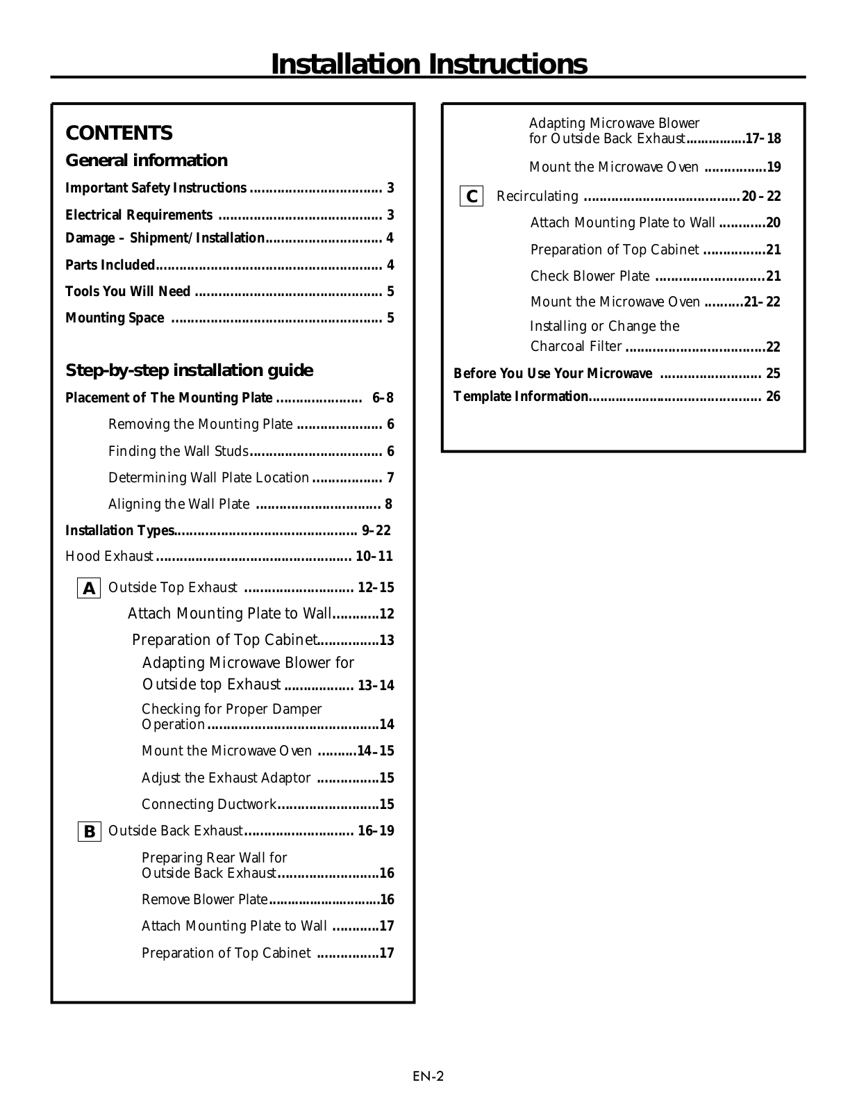
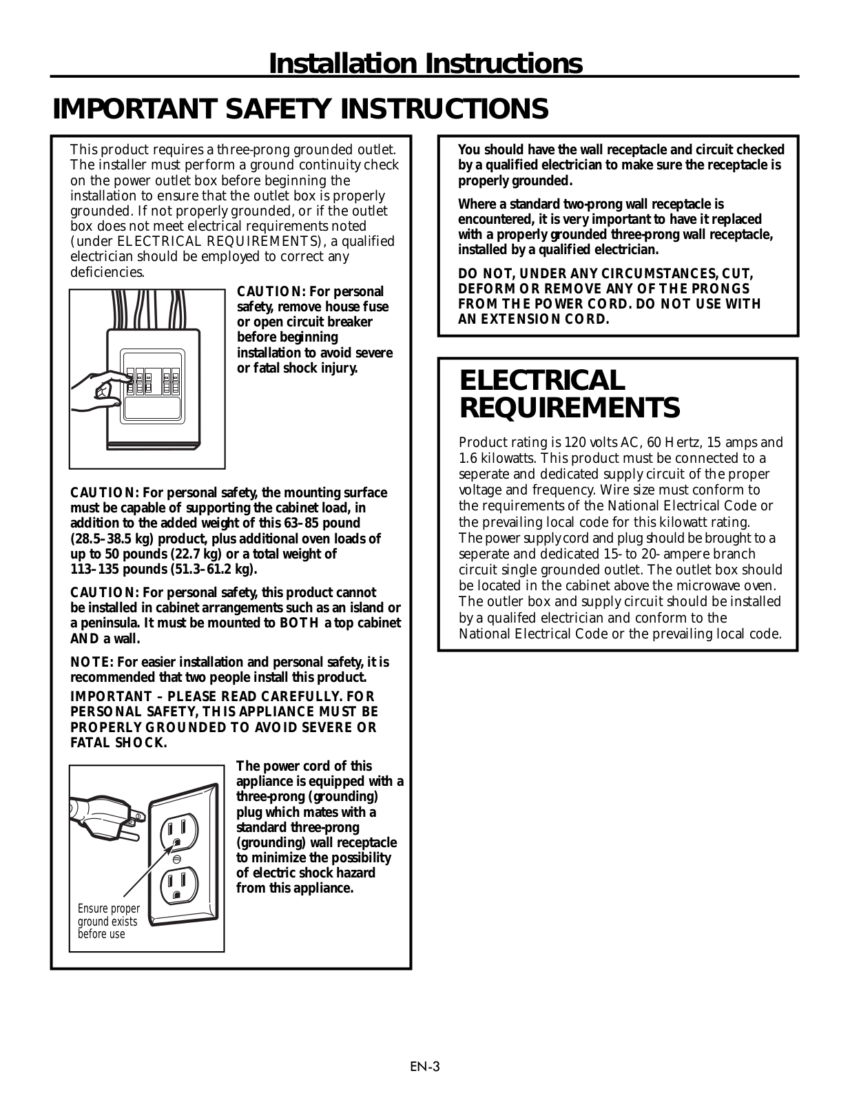
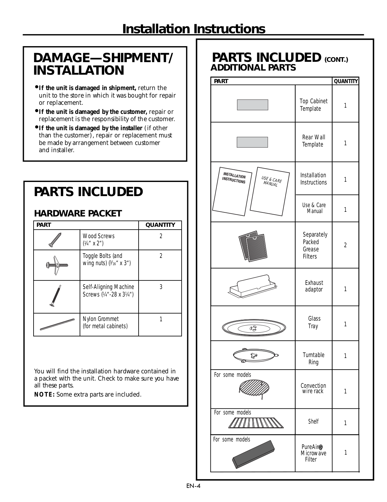
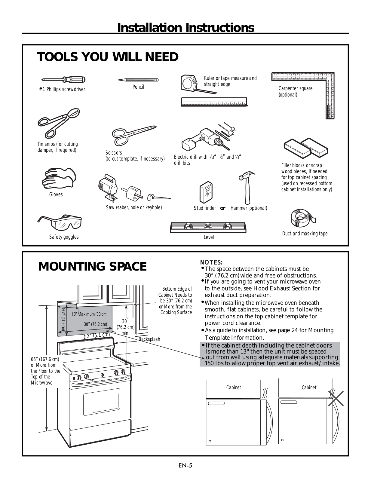
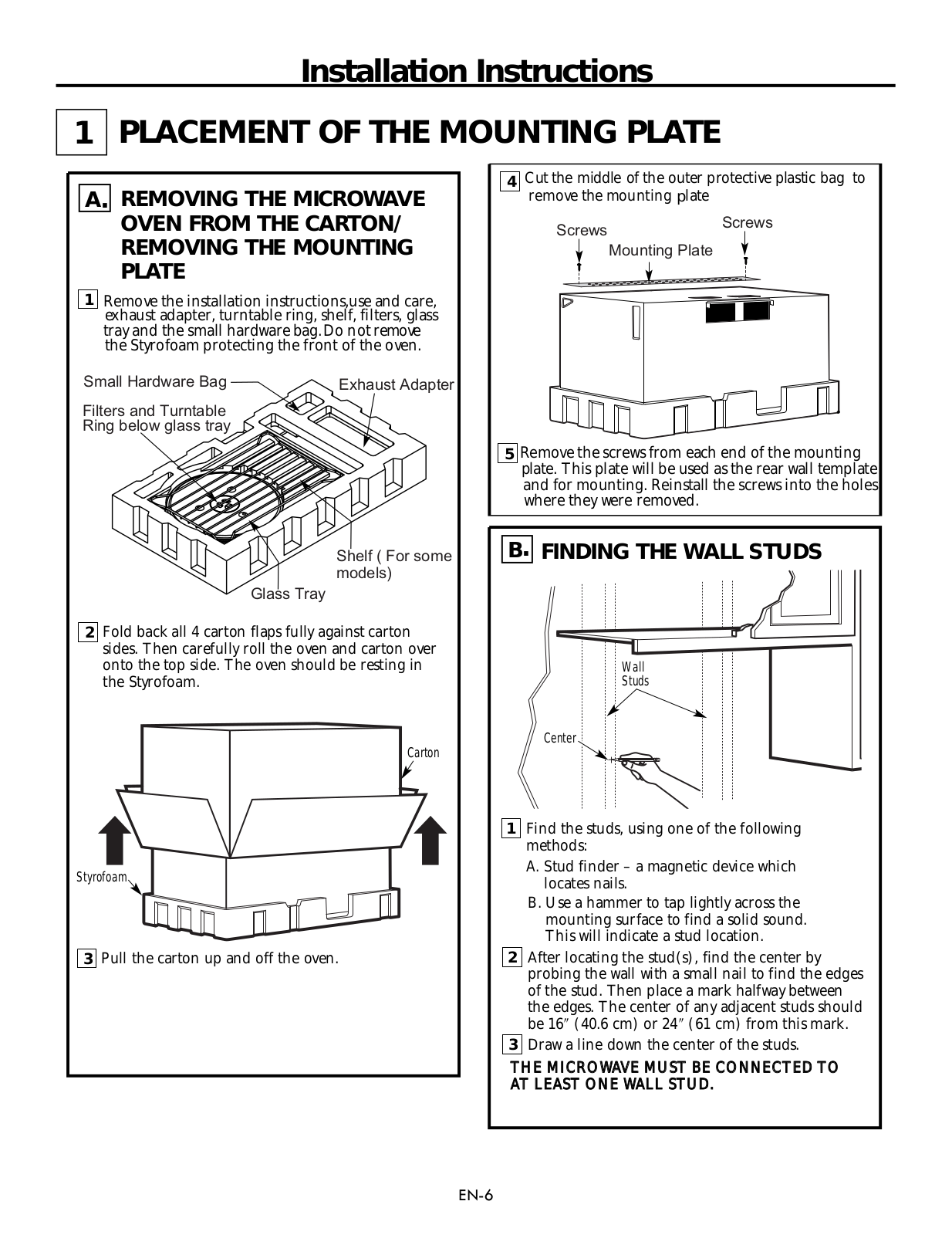
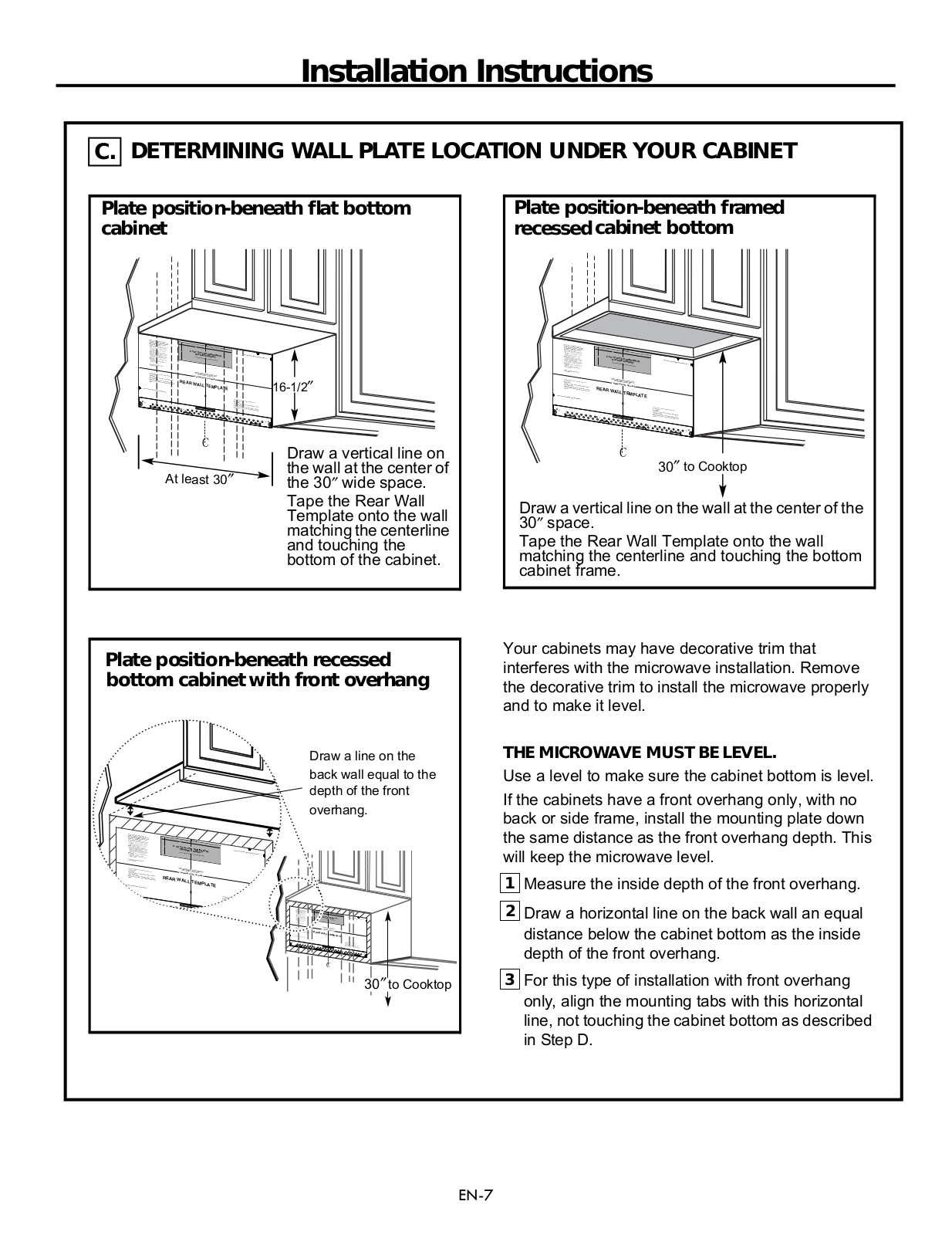
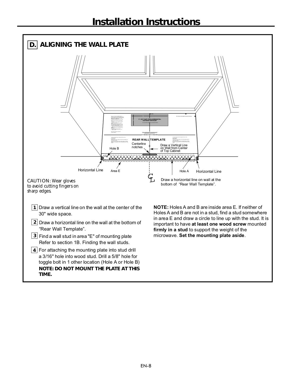
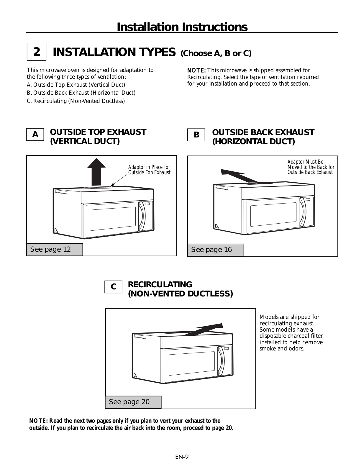
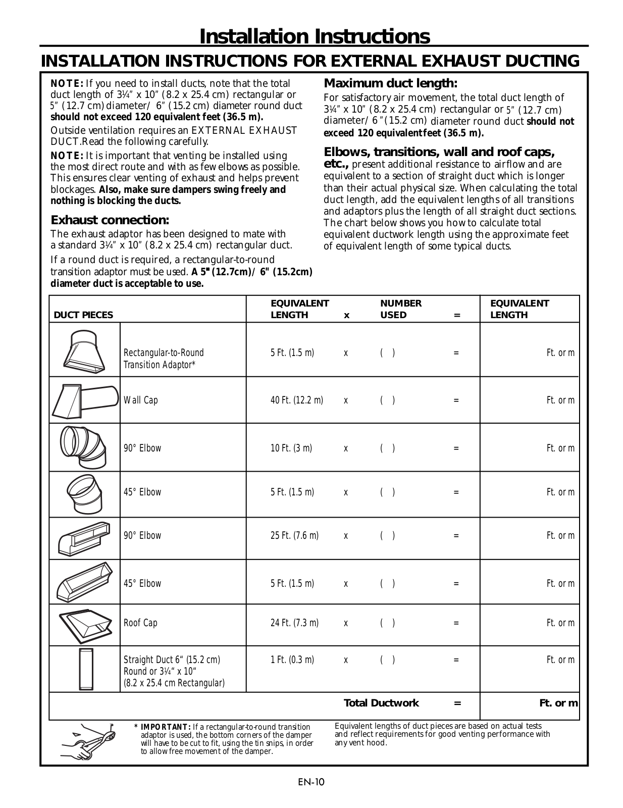
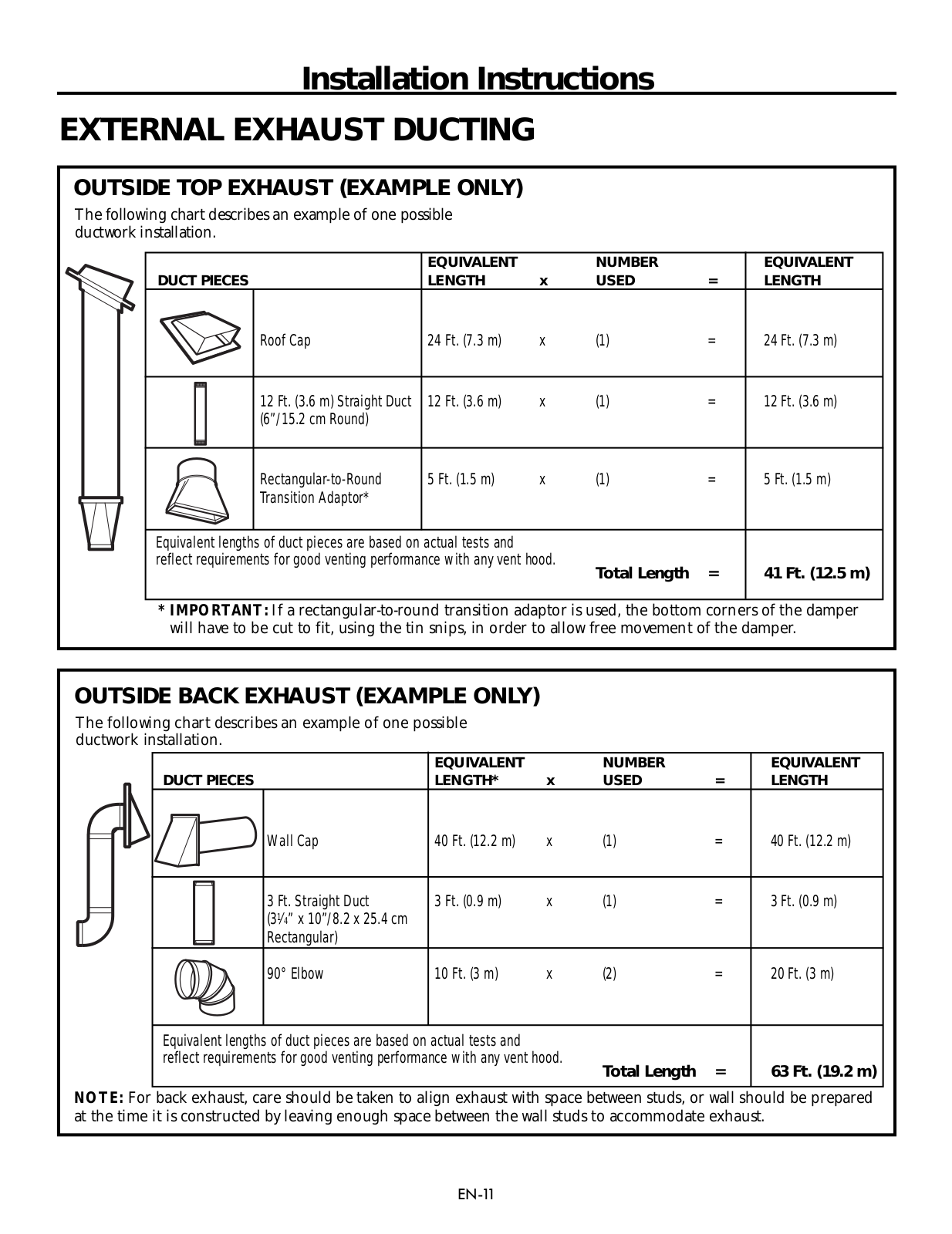
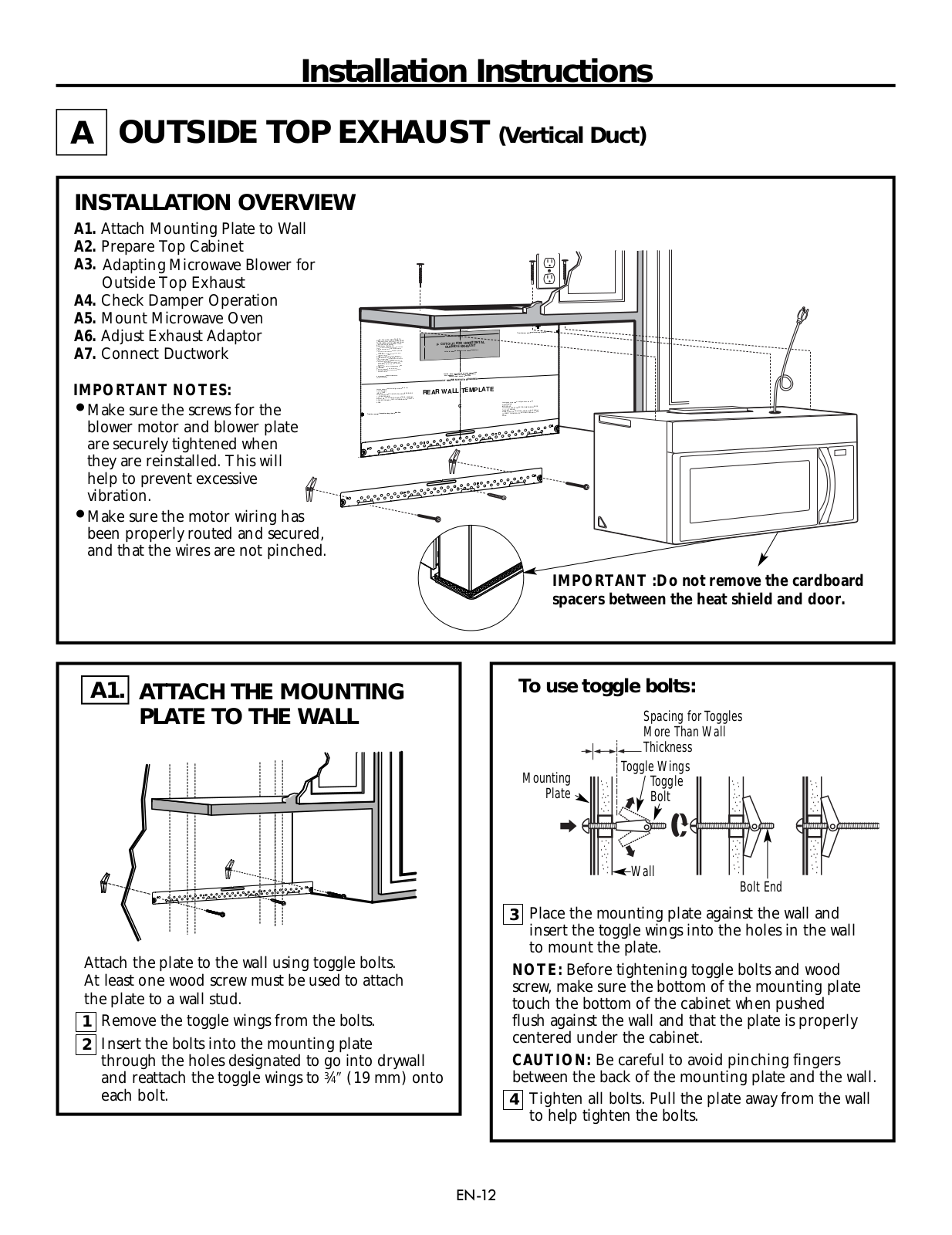
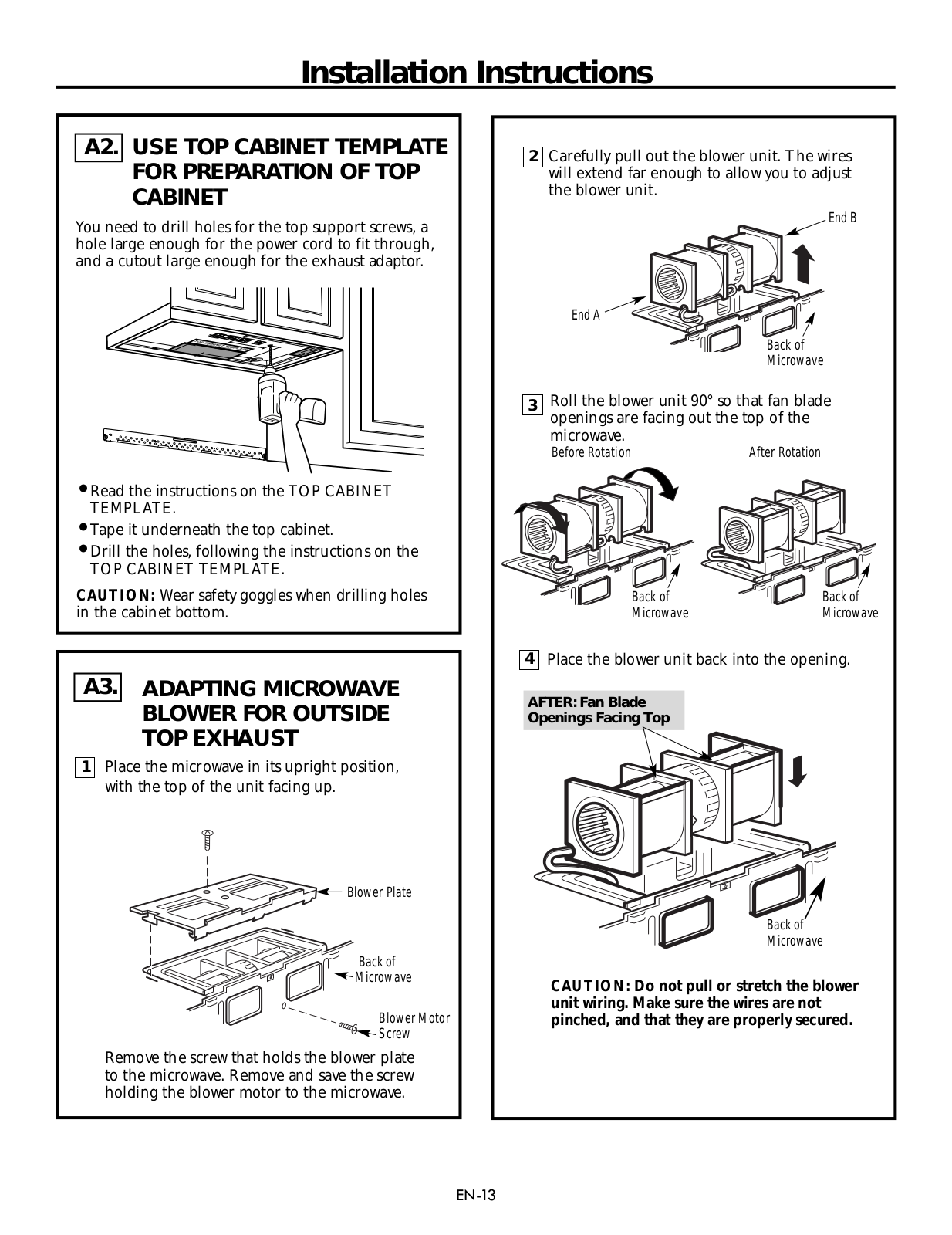
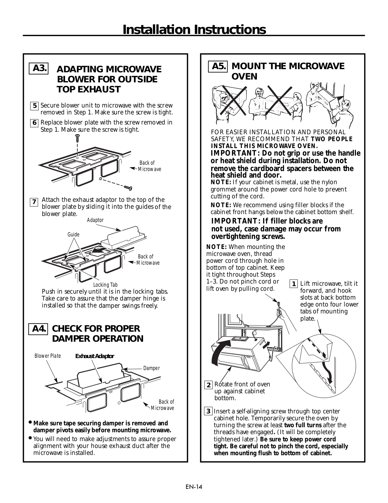
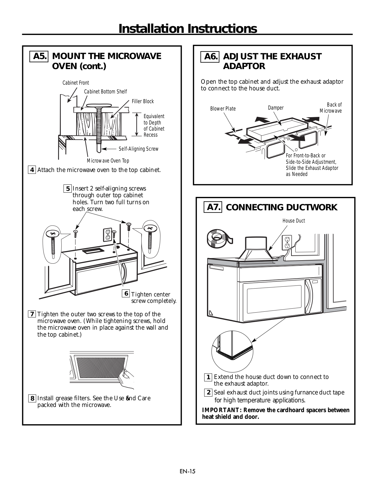
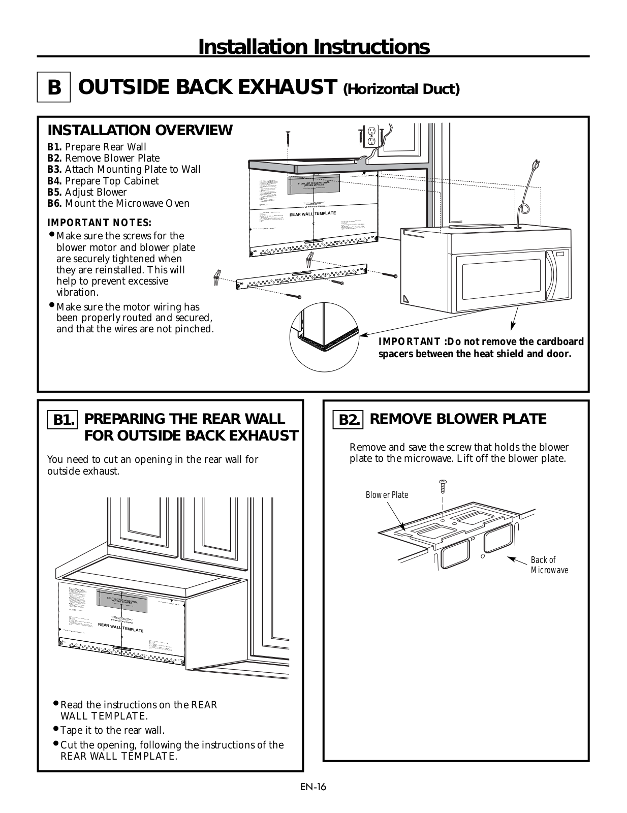
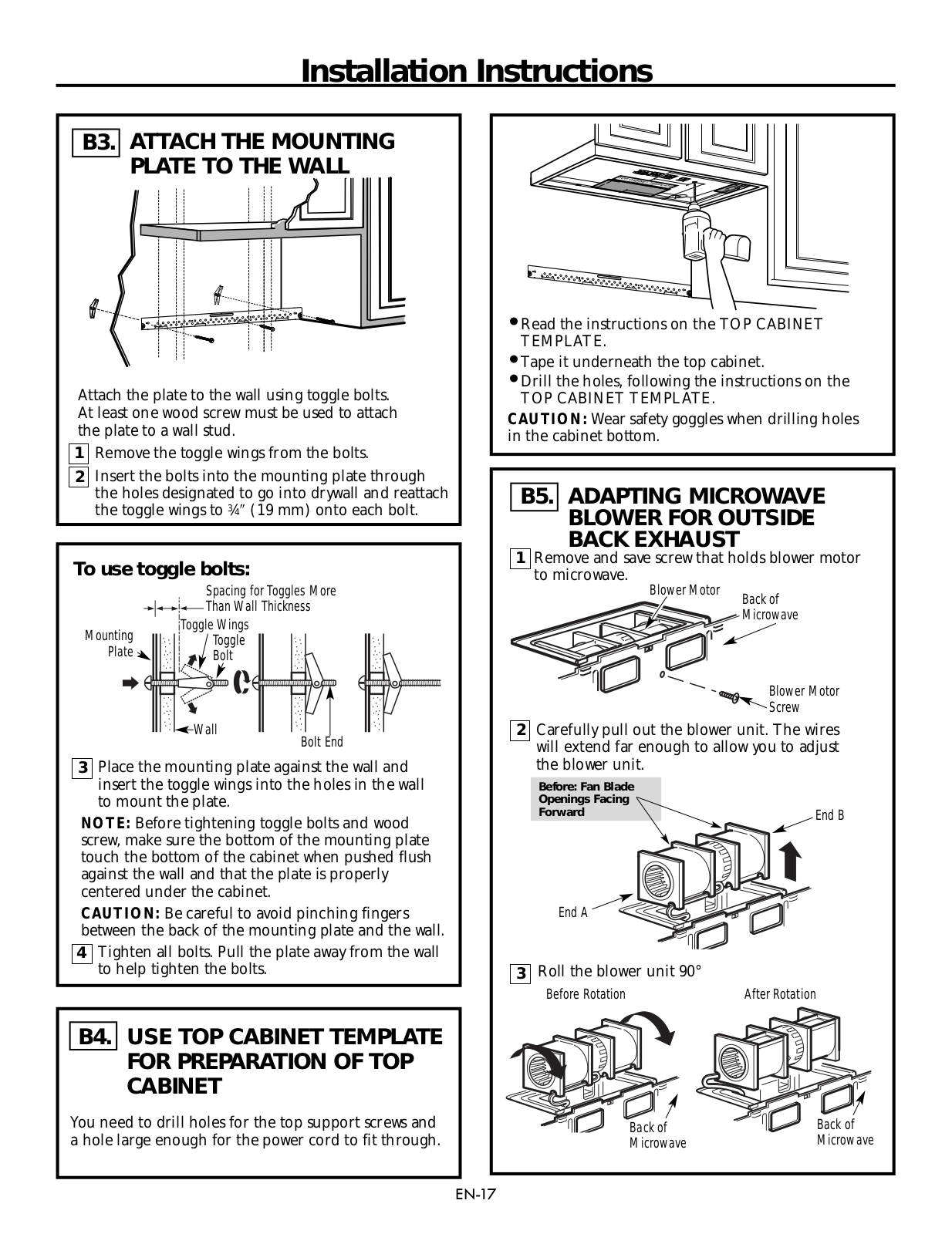
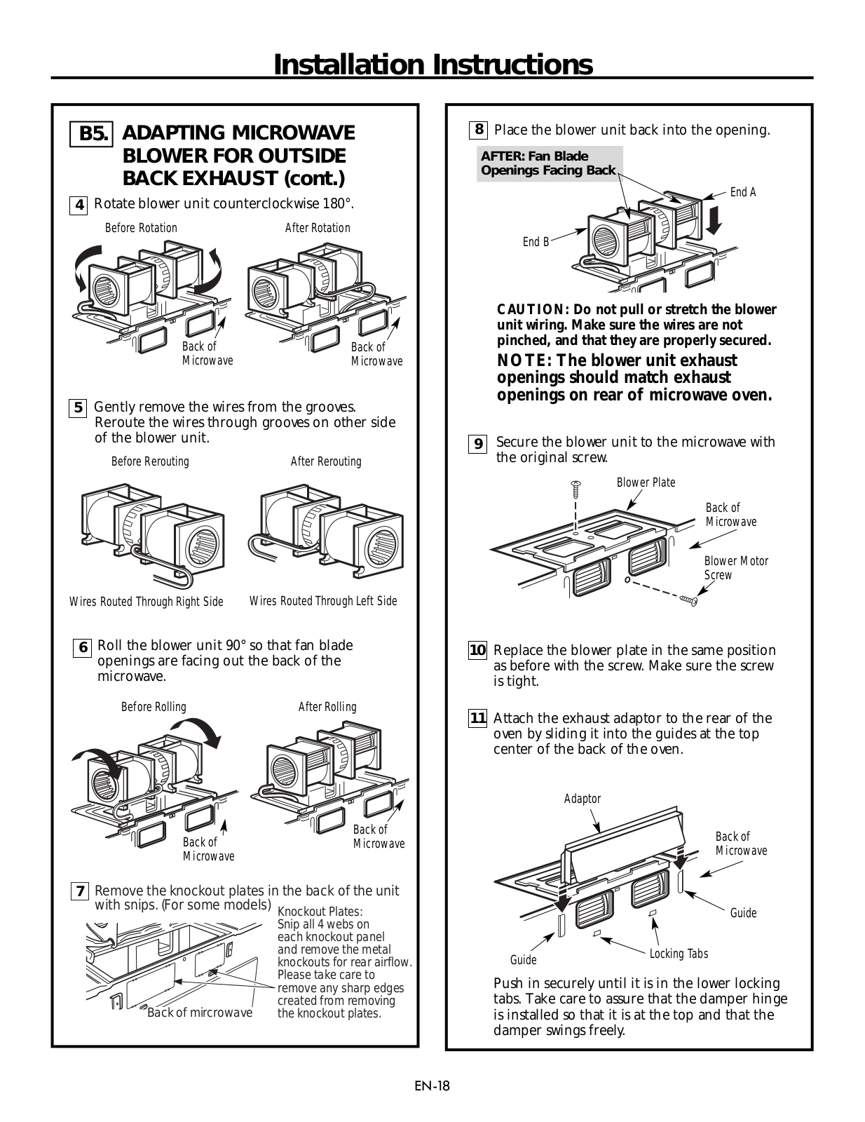
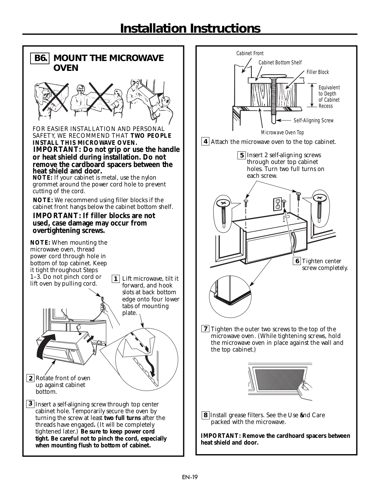
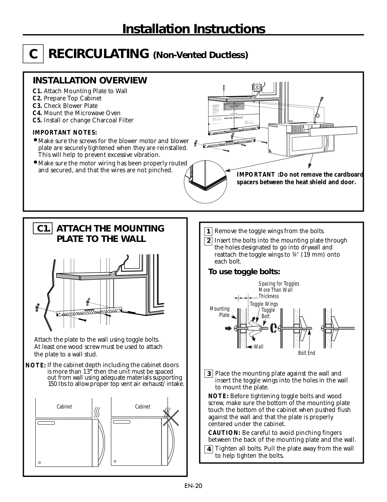
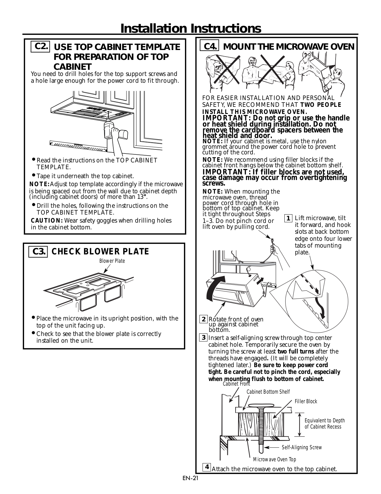
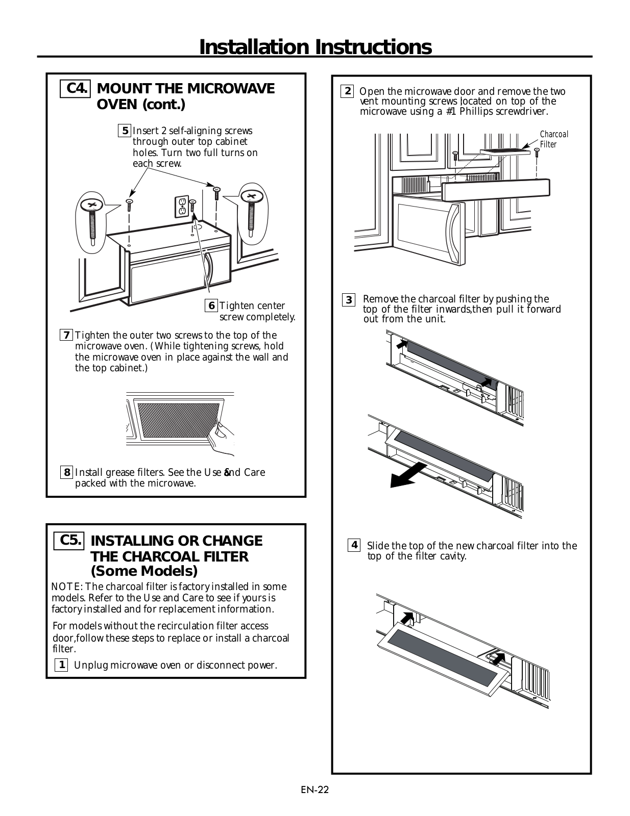
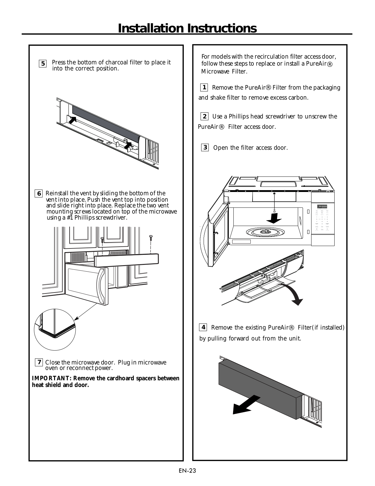
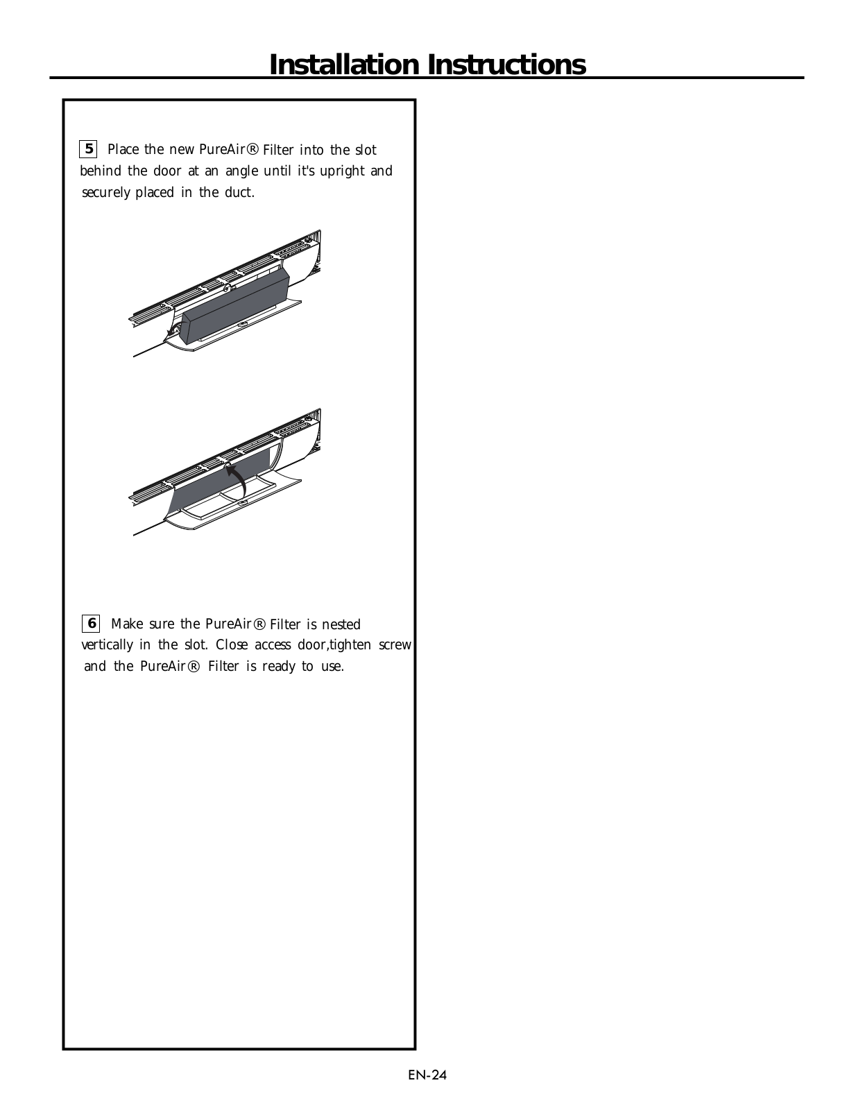
Frigidaire FFMV1745TW, FFMV1745TS, FFMV1745TB, FFMV1645TD Installation Guide
...
Frigidaire Installation Guide
Download
Specifications and Main Features
Frequently Asked Questions
User Manual
Download
Loading...
+
54
hidden pages
Unhide
You need points to download manuals.
1 point = 1 manual.
You can buy points or you can get point for every manual you upload.
Buy points
Upload your manuals