

Page 1

SERVICE DATA SHEET 318127022 (0505) Rev. A
Dual Fuel Slide-in Range with Electronic Oven Control
Gas Slide-in Range with Electronic Oven Control
NOTICE
°
This service data sheet is intended for use by persons having electrical and mechanical training and a level of
knowledge of these subjects generally considered acceptable in the appliance repair trade. The manufacturer
cannot be responsible, nor assume any liability, for injury or damage of any kind arising from the use of
this data sheet.
SAFE SERVICING PRACTICES
.
To avoid the possibility of personal injury and/or property damage, it is important that safe servicing practices be
observed. The following are examples of some, but not all, of these practices.
1. Do not attempt a product repair if you have any doubts as to your ability to complete it in a safe and satisfactory
manner.
2. Before servicing or moving an appliance, remove power cord from electric outlet, trip circuit breaker to OFF, or
remove fuse and turn off gas supply.
3. Never interfere with the proper installation of any safety device.
4. USE ONLY REPLACEMENT PARTS CATALOGED FOR THIS APPLIANCE. SUBSTITUTIONS MAY DEFEAT COMPLIANCE
WITH SAFETY STANDARDS SET FOR HOME APPLIANCES.
5. GROUNDING: The standard color coding for safety ground wires is GREEN OR GREEN WITH YELLOW STRIPES.
Ground leads are not to be used as current carrying conductors. IT IS EXTREMELY IMPORTANT THAT THE SERVICE
TECHNICIAN REESTABLISH ALL SAFETY GROUNDS PRIOR TO COMPLETION OF SERVICE. FAILURE TO DO SO
WILL CREATE A POTENTIAL HAZARD.
6. Prior to returning the product to service, ensure that:
• All electric connections are correct and secure.
• All electrical leads are properly dressed and secured away from sharp edges, high-temperature components,
and moving parts.
• All non-insulated electrical terminals, connectors, heaters, etc. are adequately spaced away from all metal
parts and panels.
• All safety grounds (both internal and external) are correctly and securely reassembled.
• All panels are properly and securely reassembled.
1
Page 2
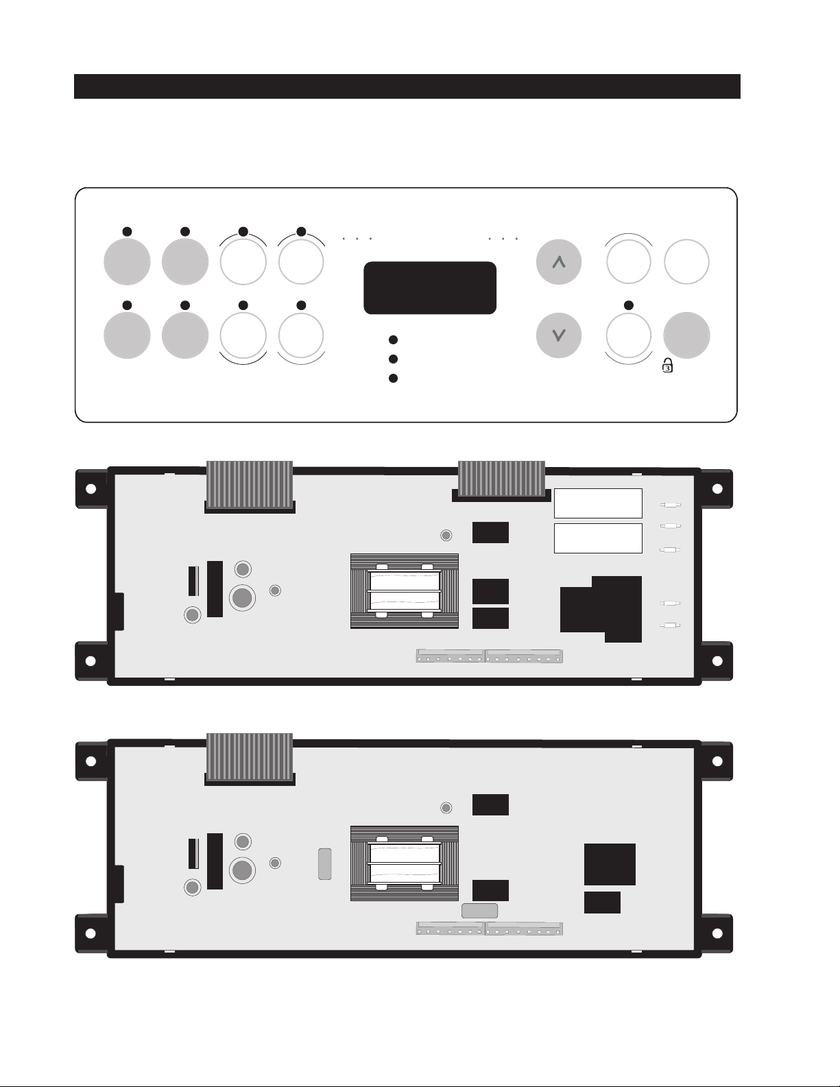
ELECTRONIC OVEN CONTROL
1. This self-cleaning controller offers Bake, Broil, Speed Bake (some models) modes, Timed and Delayed Baking, and
Cleaning functions.
2. This Controller has a touch sensitive membrane.
Speed Bake Oven
Bake
Speed
bake
Speed
clean
Bake
time
Clock
Oven
light
Broil
Keep
warm
Clean
Start
time
Oven
Preheat
Timer
On/Of f
Clear
/Of f
Controls
Door Locked
NOTE: The Controller's are not field repairable. Only temperature settings can be changed. See oven calibration.
P2
P3
P1
P7
BAKE
BROIL
L1
P4
L2 OUT
L2 IN
P12
P15
P13
P5
Dual Fuel Models
P12
P15
Gas Models
2
P5
Page 3
SPEED BAKE MODE (some models)
The speed bake oven uses the addition of a fan to move the air already in the oven. Moving the heated air helps to
destratify the heat and cause uniform heat distribution. Cooking times can be reduced by as much as 30%. The air
is drawn in through a fan shroud located on the rear wall of the oven. It is then discharged around the outer edges
of this shroud. The air circulates around the food and then enters the shroud again. There is still an oven vent which
discharges through the bottom of the control panel.
To set the control in speed bake mode, follow these steps:
1.Press the SPEED BAKE pad.
2. Enter the desired temperature on the keypad (set point).
3. Press the START pad.
The oven will automatically start and the fan will begin to run. To cancel the speed bake function, press the CANCEL
pad.
NOTE: The fan runs continuously while in the speed bake mode. The fan will stop if the door is opened. The bake
element or burner will continue to operate if the door is opened.
PREHEAT
During a preheat mode, the oven uses a bake element or burner to reach the controller set point. The element uses
full power when it's on. When the set point is reached, the preheat mode is converted to a normal bake mode.
NORMAL BAKE
Electric Oven Models: During a normal bake mode, the controller preheats the oven with the bake element. When
the desired temperature is reached, the controller adds top heat by cycling the broil element on for 12 to 18 seconds
per minute. The bake element is on for the remaining time of the minute. Both elements use full power when they
are on but they are never on at the same time. Gas Oven Models: During a normal bake mode, the controller preheats
the oven with the bake burner.
CLEAN
During a cleaning process, the oven uses bake element or burner.
CLEAN AND TIMED CLEAN
When these modes are selected, the door locks right after start button is pushed.
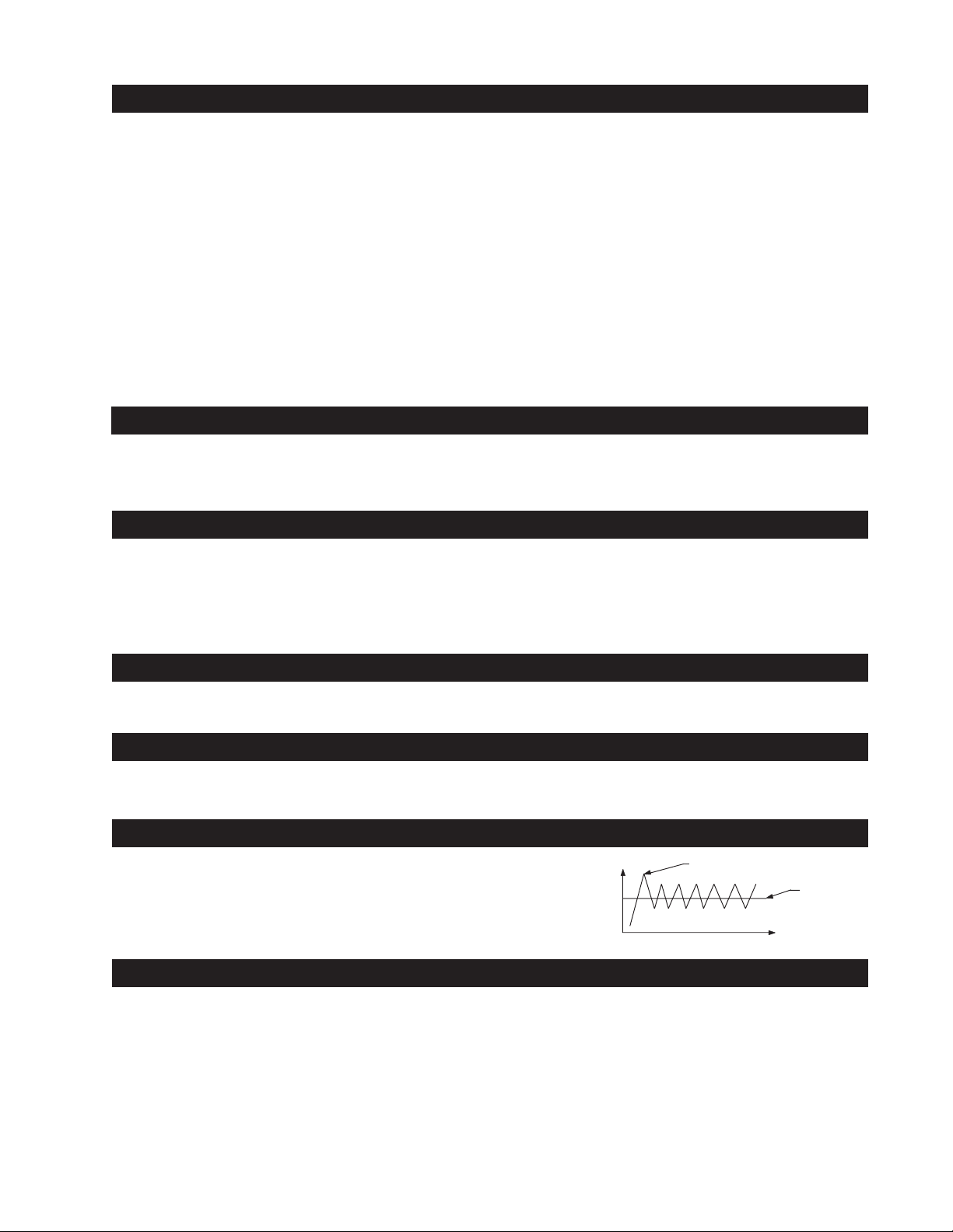
FIRST RISE
It is normal to see a temperature overshoot in the
first rise of all modes when you monitor the temperature.
T°
First rise overshoot
set point
t (sec)
OVEN CALIBRATION
Set the electronic oven control for normal baking at 350°F/176°C. Obtain an average oven temperature after a
minimum of 5 cycles. Press Cancel to end bake mode.
Note: Changing calibration affects all the cooking modes but not the clean mode.
3
Page 4

ELECTRONIC OVEN CONTROL
ELECTRONIC OVEN CONTROL (EOC) FAULT CODE DESCRIPTIONS AND RTD SCALE
Note: Only three fault codes series are displayed by this control “F1”, "F3" and “F9”. Generally speaking “F1” implies a
control failure, “F3” an oven probe problem, and “F9” a latch motor problem. In all occurrences the alarm is accompanied
by a display of “F1“.
Fault Code
Series
F1
F3
F9
Likely Failure Condition/Cause
(F10) Control has sensed a potential
runaway oven condition. Control
may have shorted relay, RTD sensor
probe may have gone bad.
(F11) Shorted keypad.
(F13) Control's internal checksum may
have become corrupted.
(F14) Misconnected flat cables.
(F30) Open RTD sensor probe/ wiring
problem. Note: EOC may initially
display an "F1", thinking a
runaway condition exists.
(F31) Shorted RTD sensor probe / wiring
problem. Note: "F3" is displayed
when oven is in active mode or an
attempt to enter an active mode is
made.
(F90 Door motor mechanism failure.
to
F94)
Suggested Corrective Action
1. Check RTD sensor probe and replace if necessary. If oven is
overheating, disconnect power. If oven continues to overheat
when the power is reapplied, replace EOC. Severe overheating
may require the entire oven to be replaced, should damage
be extensive.
2. Press CLEAR key.
3. Disconnect power, wait 30 seconds and reapply power. If
fault returns upon power-up, replace EOC.
4. Disconnect power; verify flat cable connections (P6 or P12).
1. Press CLEAR key.
2. Check wiring in probe circuit for possible open condition.
Check RTD resistance at room temperature (compare to
probe resistance chart). If resistance does not match the
chart, replace the RTD sensor probe.
3. Let the oven cool down and restart the function
1. Press CLEAR key.
2. If CLEAR key does not eliminate problem, turn off power for
30 seconds, then turn on power.
3. Check wiring of Lock Motor, and Lock Switch and Door
Switch circuits.
4. Unplug P5, apply power (L1) directly to the Lock Motor, if the
motor does not rotate, replace Lock Motor Assembly. Plug
P5.
5. Check Lock Switch A for proper operation (do they open and
close, check with ohmmeter). The Lock Motor may be
powered as in above step to open and close Lock Switch. If
the Lock Switch is defective, replace Motor Lock Assembly.
6. If all above steps fail to correct situation, replace control.
4
Page 5

RTD SCALE
Temp. °F Temp. °C Resistance (ohms)
32 ± 1.9 0.0 ± 1.1 1000 ± 4.0
75 ± 2.5 23.9 ± 1.4 1091 ± 5.3
250 ± 4.4 121.1 ± 2.4 1453 ± 8.9
ELECTRICAL RATING
(Electric Oven Models)
Kw Rating See
240/208 V nameplate
Bake Element 3400W/
Wattage 2553W
BURNER RATING
(Gas Oven Models)
Rating See
nameplate
Bake Burner 15 000BTU
350 ± 5.4 176.7 ± 3.0 1654 ± 10.8
450 ± 6.9 232.2 ± 3.8 1852 ± 13.5
550 ± 8.2 287.8 ± 4.6 2047 ± 15.8
650 ± 9.6 343.3 ± 5.3 2237 ± 18.5
Broil Element 2750W/
Wattage 2065W
OVEN TEMPERATURE
SENSOR
Broil Burner 12 000BTU
900 ± 13.6 482.2 ± 7.6 2697 ± 24.4
CIRCUIT ANALYSIS MATRIX
ELEMENTS
Bake
P2
Bake X X* X
Broil X X
Speed Bake X X X
Clean X X
Locking X NC NO
Locked NO NC
Unlocking X NO NC
Unlocked NC NO
Light X
Door Open X X
Door Closed
Broil
P3
Speed
Bake fan
P5-3
Light
P5-8
Door Motor
P5-6
Lock Motor Switches
P15-1
&
P15-2
P15-1
A
&
P15-7
Cooling fan
DLB
L2 out
Door Switch
P15-3
COM-NO
* Denotes Topheat (Dual Fuel Models Only) Relay will operate in this condition only
2 SPEEDS COOLING FAN
Electric Oven Models: A three way thermostat (140°F/170°F) controls the cooling fan speeds. The high speed
should engage in clean mode only. Low speed is engaged on all cooking modes.
Gas Oven Models: A three way thermostat (140°F/170°F) controls the cooling fan speeds. The high speed should
engage in clean mode only. Low speed may engage in broil mode after 25 minutes approximately.
5
Page 6

EXPLODED VIEW OF SPEED BAKE SYSTEM (some models)
FAN BLADE
Speed Bake Fan
Motor Assembly
Mounting Plate
Oven Cavity
Fan Nut
Speed Bake
Fan Blade
Convection
Fan Cover
Fan Cover Screws
The fan blade is mounted in the rear of the unit and has a "D" shaped mounting hole. Only minimum clearance exists
between the oven back, fan blade, and fan shroud. Be careful not to bend blade when removing or installing.
Access to the fan blade is gained by removing the fan shroud, held in place by three screws, from the inside of the oven.
The fan blade is held in place with a hex nut that has left handed threads. When removing this nut, gently hold the
fan blade, and turn the nut clockwise. If one of the blades becomes deformed, it may be bent back into shape using
a flat surface as a reference.
A flat washer is located on the motor shaft between the snap ring on the shaft and the fan blade.
NOTE: If the fan blade is bent and motor vibrations increase, the noise made by the fan will be greater.
MOUNTING PLATE OVEN
The fan motor on the rear of the unit is mounted to the main back (with three screws). There is a mounting plate held
in place between the main back (with 2 screws) and the rear oven wall (with 2 screws). Should it be necessary to replace
the oven cavity, you must remove the 2 screws located inside the unit at the rear of the oven cavity.
FAN MOTOR
The 120 volt fan motor is located on the outside of the rear of the oven.
6
Page 7

FAN RELAY
The fan motor runs continuously while in the speed bake mode unless the door is opened. If the fan does not operate,
check the following:
• Display illuminated on the electronic control.
• Voltage output between terminals P5-3 and Neutral.
• 120 Volts available at fan motor.
• Fan motor coil resistance 15.0 ohms ± 10%.
• Door/light switch.
DOOR LOCK MECHANISM
The appliance is equipped with an electronic oven control
and has an auto locking door latch feature. When the self
clean cycle is programmed, the door is locked by a motor
operated latch system. The interior of oven doesn't need to
heat up to 500°F/260°C before the door locks. However, until
the temperature inside oven reaches 500°F/260°C, the selfclean program can be canceled and door will unlock
immediately. After oven reaches temperatures over 500°F/
260°C, the door will not unlock until temperature drops
below 500°F/260°C.
If a problem appears and the door stays locked it is possible
for the servicer to unlock the door without removing the
appliance from its place. Follow the steps below:
1. Trip the circuit breaker to OFF position.
2. Remove the 2 screws, which are fixing the oven door
latch, located between the control panel and the oven
door.
3. When the screws are removed it is possible to unlock the
latch with a flat screwdriver, or one of the tools supplied
with the wall oven which are used to take off the oven
from the cabinet. Insert the tool tip through the slot on top
of the oven door. During this step it's important to take
care to not damage the appliance.
4. As soon as the latch is in the unlock position, you can
open the door.
5. Replace the motor latch:
1. To have access to the door latch assembly, remove the 3 screws under the control panel which are fixing it.
2. Remove the access plate located on the upper air channel by removing the screw.
3. Replace the motor latch by a new one and reassemble in reverse order.
Motor Cooling Fan
Upper Air Channel
Access Plate
Door Locking
Mechanism
Assembly
Safety
Thermostat
7
Page 8

OVEN DOOR REMOVAL AND REPLACEMENT
To Remove the Oven Door:
1. Open the door to the fully opened position.
2. Pull up the lock located on each hinge supports and engage it in the hinge lever. You may have to apply a little
downward pressure on the door to pull the locks fully over the hooks.
3. Grab the door by the sides, pull the bottom of the door up and toward you to disengage the hinge supports.
Keep pulling the bottom of the door toward you while rotating the top of the door toward the range to completely disengage the hinge levers.
To Replace the Oven Door:
1. Grab the door by the sides; place the hinge supports in the hinge slots. Open the door to the fully opened
position.
2. Disengage the lock from the hinge levers on both sides.
Note: Make sure the hinge supports are fully engaged before unlocking the hinge levers.
3. Close the oven door.
The door is heavy. After removing door, lay it flat on the floor with the inside of the door facing down.
Hinge
lever
Hinge
support
Lock in normal position Lock engaged for door
removal
HINGE SLOT
Door removed
from the range
8
 Loading...