

Page 1

VRPXEMWRT2
Wireless VRP® Energy Management Wall
Controller with an Occupancy Sensor
INSTRUCTION MANUAL
PART NO. 95200303 Rev 00
VPXEMWRT2-Thermostat Manual_pkg.indd 1 2017-12-15 3:37 PM
Page 2

VPXEMWRT2-Thermostat Manual_pkg.indd 2 2017-12-15 3:37 PM
Page 3

3
Table of Contents
Introduction ............................................................................................................ 5
Before you begin ................................................................................................... 7
Wall Controller Installation ..................................................................................... 9
Pairing the Wall Controller and the Receiver .........................................................9
Mounting the Wall Controller to the wall ................................................................ 9
Installing the Wireless Receiver ..................................................................... 10-11
Wall Controller Wiring Installation .............................................................................12-14
Wall Controller Conguration ...............................................................................15
Setting the Wall Controller Clock ................................................................................... 16
Entering the Room Number ........................................................................................... 17
Conguring the Energy Saving Settings ....................................................................... 18
Testing the Wall Controller .............................................................................................19
Custom Energy Savings Settings .................................................................................. 20
Using the Wall Controller Settings Screens .........................................................21
01 – FAN CONTROL MODE ...............................................................................22
02 – 1ST STAGE DIFFERENTIAL - HEAT ............................................................ 23
03 – 2ND STAGE DIFFERENTIAL - HEAT ............................................................ 24
04 – 1ST STAGE DIFFERENTIAL - COOL .........................................................25
05 – INCIDENTAL OCCUPANCY THRESHOLD ................................................. 26
06 – NIGHT OCCUPANCY THRESHOLD ........................................................... 27
07 – NA ................................................................................................................ 28
08 – NIGHT OCCUPANCY START ..................................................................... 29
09 – NIGHT OCCUPANCY END ......................................................................... 30
10 – NA ................................................................................................................ 31
11 – NA ................................................................................................................ 32
12 – TEMPERATURE SETBACK DELAY - HEAT ............................................... 33
13 – MINIMUM SETBACK TEMPERATURE ...................................................... 34
14 – TEMPERATURE SETBACK DELAY - COOL .............................................. 35
15 – MAXIMUM SETBACK TEMPERATURE...................................................... 36
16 – NA ................................................................................................................ 37
17 – MINIMUM SET POINT.................................................................................38
18 – MAXIMUM SET POINT ...............................................................................39
VPXEMWRT2-Thermostat Manual_pkg.indd 3 2017-12-15 3:37 PM
Page 4

4
Table of Contents
19 – TEMPERATURE CONTROL MODE ........................................................... 40
20 – AUTO CHANGEOVER SET POINT OFFSET (DEAD BAND) ..................... 41
21 – SETBACK SET POINTS / AUTO-RESTORE .............................................. 42
22 – AUTOMATIC HUMIDITY CONTROL† .......................................................... 43
23 – TEMPERATURE CALIBRATION ................................................................. 44
Wall Controller Maintenance ...............................................................................45
Replacing Wall Controller Batteries ..................................................................... 46
Troubleshooting ................................................................................................... 47
Error Codes ......................................................................................................... 47
Wall Controller is not controlling the VRP unit. .................................................... 48
APPENDIX 1 - Energy Saving Presets................................................................ 49
APPENDIX 2 - Glossary ...................................................................................... 50
Technical Specications ...................................................................................... 51
VPXEMWRT2-Thermostat Manual_pkg.indd 4 2017-12-15 3:37 PM
Page 5

5
Introduction
Friedrich VRPXEMWRT2 Energy Management Wall Controllers for the hospitality
industry deliver unprecedented energy savings without compromising guest
comfort. Integrated occupancy sensor uses a combination of motion and thermal
sensing technologies for accurate occupancy detection. Reliable occupancy
detection allows saving energy when rooms are unoccupied.
Energy saving presets eliminate the guesswork and make it easy to adjust the
energy saving settings. (Patent Pending) Fully congurable energy saving
settings allow customizing the Wall Controller energy saving settings to t any
situation.
Large buttons with international symbols make it easy to adjust the temperature
in ±1° °F or °C and control the fan speed.
Built-in wireless mesh-networking enables optional remote management. For
installation of a networking Wall Controller with remote management, refer to the
“Network Installation” manual.
FOR INSTALLATION OF NETWORKING WALL CONTROLLERS WITH REMOTE
MANAGEMENT, REFER TO THE NETWORK INSTALLATION” MANUAL.
LOGIN TO THE REMOTE MANAGEMENT WEBSITE TO CONFIRM THE SERVER IS
CONNECTED TO THE INTERNET BEFORE INSTALLING WALL CONTROLLERS.
DO NOT INSTALL WALL CONTROLLERS IF THE SERVER IS NOT CONNECTED TO
THE INTERNET. STOP THE INSTALLATION AND CONTACT TECHNICAL SUPPORT.
START BY FIRST INSTALLING A WALL CONTROLLER IN THE ROOM CLOSEST TO
THE SERVER.
LOG IN TO REMOTE MANAGEMENT WEBSITE TO CONFIRM THAT THE WALL
CONTROLLER IS ON THE REMOTE MANAGEMENT WEBSITE WITH THE
CORRECT ROOM NUMBER. CONTINUE BY INSTALLING ADDITIONAL WALL
CONTROLLERS IN ADJACENT ROOMS ONLY AFTER CONFIRMING THAT
INSTALLED WALL CONTROLLER(S) HAVE CONNECTED TO THE WIRELESS
NETWORK AND THE REMOTE MANAGEMENT WEBSITE .
IF INSTALLED WALL CONTROLLER(S) ARE NOT CONNECTING TO THE
NETWORK AND DO NOT APPEAR ON THE REMOTE MANAGEMENT WEBSITE
WITH THE CORRECT ROOM NUMBER, STOP THE INSTALLATION AND CONTACT
TECHNICAL SUPPORT THE ROOMS FURTHEST AWAY FROM THE SERVER
SHOULD BE INSTALLED LAST.
VPXEMWRT2-Thermostat Manual_pkg.indd 5 2017-12-15 3:37 PM
Page 6

6
VPXEMWRT2-Thermostat Manual_pkg.indd 6 2017-12-15 3:37 PM
Page 7

7
Before You Begin
• Determine the appropriate installation location for the Wall Controller.
The Wall Controller should face the bed area of the room.
• Wall Controller MUST NOT BE INSTALLED NEAR OR ON METAL
STRUCTURES OR SURFACES INCLUDING METAL AIR DUCTING
THAT MAY BE IN THE WALL. METAL STRUCTURES AND SURFACES
SIGNIFICANTLY REDUCE THE RANGE OF THE WIRELESS SIGNAL
VPXEMWRT2-Thermostat Manual_pkg.indd 7 2017-12-15 3:37 PM
Page 8

8
Wall Controller Installation
Pairing the Wall Controller and the Receiver
Wall Controller and Receiver must be paired in order to operate together. Once
paired, the Wall Controller cannot be used with another wireless Receiver without
repeating the pairing procedure. Friedrich Wall Controllers are pre-linked with the
card in the box.
In case of Network Installation with Remote Management, the Wall Controller and
the Receiver must be paired with a Network Programmer specic to the property
before the installation.
Wall Controller and Receiver must not be powered during the pairing procedure remove batteries from the Wall Controller and unplug the Receiver from the
VRP unit during the pairing procedure.
• Plug one programmer connector into the Wall Controller;
• Plug the other programmer connector into the Receiver;
• Push the black button on the programmer. The red light on the programmer
should turn on and remain steadily lit;
If the red light on the programmer is blinking or is not steadily lit, unplug the
programmer from the Wall Controller and the Receiver and repeat the steps
above.
• Unplug the programmer from the Wall Controller and the Receiver;
VPXEMWRT2-Thermostat Manual_pkg.indd 8 2017-12-15 3:37 PM
Page 9

9
Mounting the Wall Controller to the wall
• Remove the Wall Controller cover;
• Use the supplied wall anchors and mounting screws to secure the Wall
Controller to the wall;
• Insert two (2) AA-cell batteries (not-supplied) into the Wall Controller battery
compartment;
• Follow the “Wall Controller Conguration” instructions;
• Replace the Wall Controller cover and screw in the locking screw;
Wall Controller Installation
VPXEMWRT2-Thermostat Manual_pkg.indd 9 2017-12-15 3:37 PM
Page 10
10
Installing the Wireless Receiver
• Unplug the VRP® unit from power supply.
• Connect the low voltage wires to screw terminals on the VRP® unit low
voltage terminal block - refer to the Wiring Table to determine proper
connections.
• Ensure that the Wireless Receiver antenna is not touching any metal
components of the VRP® unit.
• Ensure that the Wireless Receiver antenna is facing the Wall Controller
on the wall and is oriented so that any metal parts of the VRP® unit do not
obstruct the wireless communication to the Wall Controller and, in case of a
network installation, to other wireless Receivers and the server.
• Plug the VRP® unit to power supply.
Wall Controller Installation
Receiver
VPXEMWRT2-Thermostat Manual_pkg.indd 10 2017-12-15 3:37 PM
Page 11

11
Wall Controller Installation
Installing the Wireless Receiver
Mount the Receiver as high as
possible. It MUST be higher than
the VRP unit (top)
To maximize the wireless signal
strength from the Receiver to the
VRPXEMWRT2 Wall Controller,
the Receiver MUST NOT be
installed on the VRP unit.
Note: Depending upon the closet size, an appropriate length of Field Supplied
CAT 6 cable will be required.
VPXEMWRT2-Thermostat Manual_pkg.indd 11 2017-12-15 3:37 PM
Page 12

12
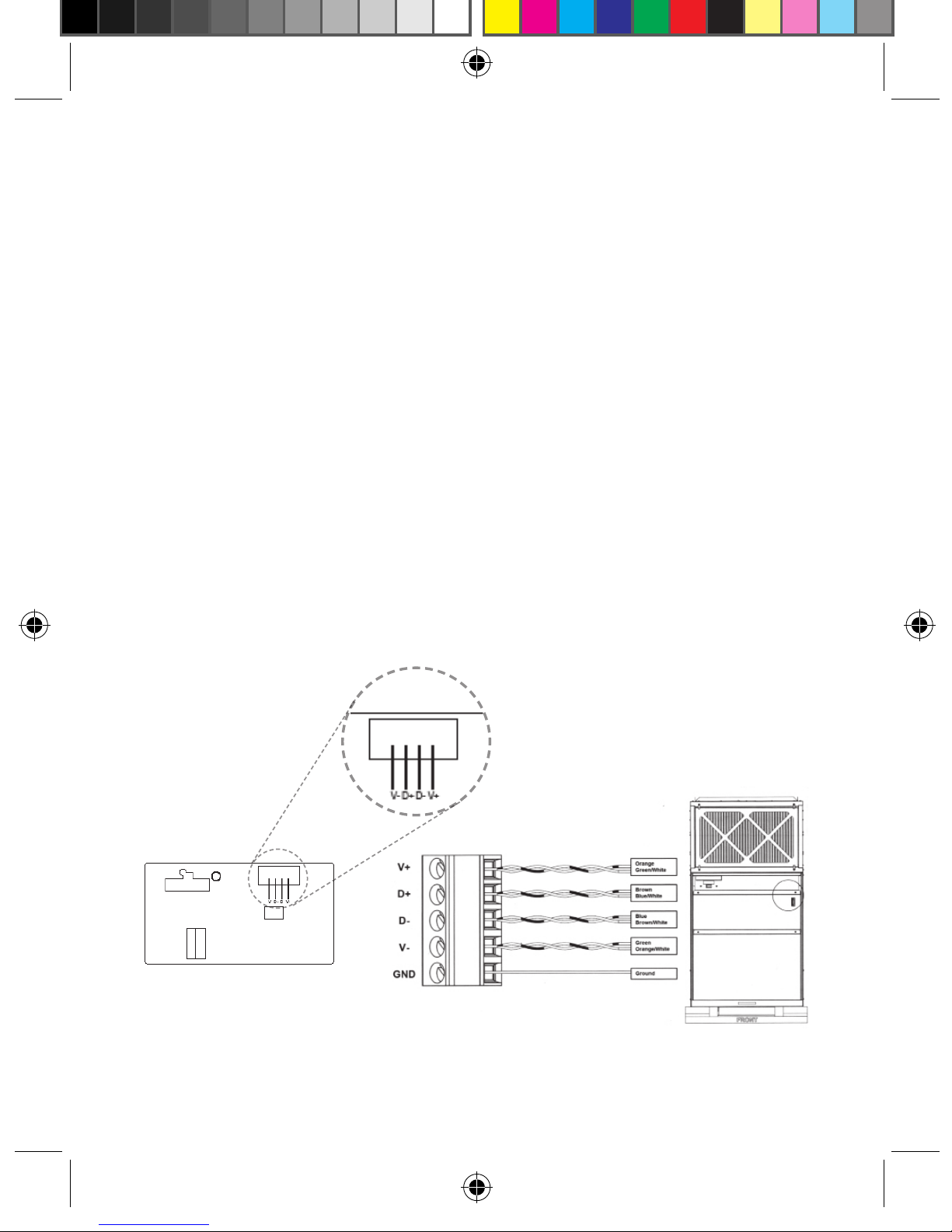
Wall Controller Wiring Installation
There are four sets of connections for the VRPXEMWRT2 Wall Controller. The
supplied cable from the VRPXEMWRT2 Receiver as shown in Figure 1, has four
color coded wires. Each of these wires must be connected to two Cat6 wires as
shown in Figure 2. Each connection is made with a lever type connector. Four
connectors will be needed to complete unit wiring. Each connector is capable of
connecting three wires.
Figure 1
Figure 2
WIRE COLOR LABEL
Orange
Connection 1
V+
Orange
Green/White
Brown
Connection 2
D+
Brown
Blue/White
Blue
Connection 3
DBlue
Brown/White
Green
Connection 4
VGreen
Orange/White
Ground Shield
Wire
GND
VPXEMWRT2-Thermostat Manual_pkg.indd 12 2017-12-15 3:37 PM
Page 13
13
Wall Controller Wiring Installation
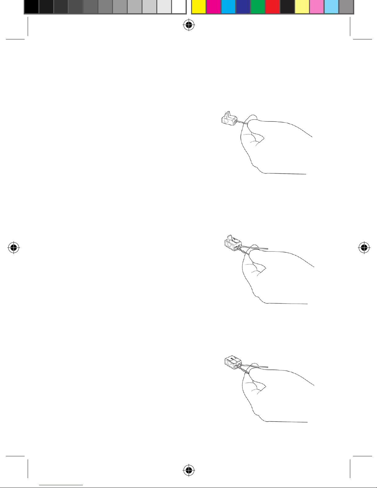
General Connection Procedure:
1. Remove 2” of the outer sheath of the
CAT6 cable including the shield and
strip the wires.
2. Insert the specied wire from the
Receiver into a slot of the
lever connector as shown in Figure 3
and close lever as shown in Figure 4.
3. Insert two specied twisted, paired
wires from the CAT6 cable into the
remaining lever connector slot as
shown in Figure 4. Each twisted,
paired wire should be inserted into
its own separate slot in the lever
connector.
4. Close the orange lever on the lever
connector as shown in Figure 5.
Make sure the levers seat properly.
Figure 3.
Figure 4.
Figure 5.
VPXEMWRT2-Thermostat Manual_pkg.indd 13 2017-12-15 3:37 PM
Page 14

14
Connection 1
Insert the Orange (V+) wire from the Receiver into a lever connector slot and
close the orange lever on the connector.
Insert the twisted Orange and Green/White Cat 6 wires into the remaining lever
connector slot and close the orange lever on the connector.
Connection 2
Insert the Brown (D+) wire from the Receiver into a lever connector slot and
close the orange lever on the connector.
Insert the twisted Brown and Blue/White Cat 6 wires into the remaining lever
connector slot and close the orange lever on the connector.
Connection 3
Insert the Blue (D-) wire from the Receiver into a lever connector slot and close
the orange lever on the connector.
Insert the twisted Blue and Brown/White Cat 6 wire into the remaining lever
connector slot and close the orange lever on the connector.
Connection 4
Insert the Green (V-) wire from the Receiver into a lever connector slot and close
the orange lever on the connector.
Insert the twisted Green and Orange/White Cat 6 wire into the remaining lever
connector slot and close the orange lever on the connector.
WIRE COLOR LABEL
Orange
Connection 1
V+
Orange
Green/White
Brown
Connection 2
D+
Brown
Blue/White
Blue
Connection 3
DBlue
Brown/White
Green
Connection 4
VGreen
Orange/White
Ground Shield
Wire
GND
Wall Controller Wiring Installation
VPXEMWRT2-Thermostat Manual_pkg.indd 14 2017-12-15 3:37 PM
Page 15

NOTE: You can access Wall
Controller Conguration settings
at any time by pressing the
“Conguration” button.
NOTE: If the Wall Controller is connected to a network, the equipment and the
energy saving settings congured on the Wall Controller will be ignored and the
settings congured on the Remote Management
Website will be applied.
CONFIGURATION
BUTTON
15
Wall Controller Conguration
Once the Wall Controller is powered, Wall Controller conguration settings will
appear on the Wall Controller screen.
In order to properly operate the VRP unit:
• Set the Wall Controller clock;
• Enter the room number;
• Select Energy Savings Preset;
The Wall Controller conguration screens have a 3-minute time-out. If no action
is taken within three (3) minutes, the Wall Controller will exit conguration
settings.
NOTE: If the Wall Controller is connected to a network, the equipment settings
congured on the Wall Controller will be ignored and the Wall Controller settings
congured through the network will be applied.
VPXEMWRT2-Thermostat Manual_pkg.indd 15 2017-12-15 3:37 PM
Page 16

16
Wall Controller Conguration
Setting the Wall Controller Clock
Set the Wall Controller clock to current time in 24h (Military Time) format.
• Use the “Up” and “Down” buttons to set the hours;
• Press the “Fan” button to advance to the minutes setting;
• Use the “Up” an “Down” buttons to set the minutes;
• Press the “F/C” button to advance to the next menu;
Setting the clock correctly is crucial for proper operation of the Wall Controller.
HOURS MINUTES
VPXEMWRT2-Thermostat Manual_pkg.indd 16 2017-12-15 3:37 PM
Page 17

17
Wall Controller Conguration
Entering the Room Number
Enter the room number by changing the digits on the screen. Leading zeros “0”
preceding other digits will be ignored, i.e. Room number “123” should be entered
as “00123”.
• Use the “Up” and “Down” buttons to change the digit;
• Press the “Fan” button advance to the next digit;
• Press the “F/C” button to advance to the next menu;
Entering the room number correctly is crucial for proper operation of remotely
managed Wall Controllers.
VPXEMWRT2-Thermostat Manual_pkg.indd 17 2017-12-15 3:37 PM
Page 18

18
Wall Controller Conguration
Conguring the Energy Savings Settings
Use the “Up” and “Down” buttons to select the Energy Saving preset:
E-0* Energy Savings Off - No Temperature Setback;
E-1 Lowest Energy Savings;
E-2 Lower Energy Savings;
E-3 Standard Energy Savings;
E-4 Higher Energy Savings;
E-5 Highest Energy Savings;
Refer to the APPENDIX 1 for Energy Saving Preset details.
E-C Indicates “Custom Energy Savings Settings” in case the active
Wall Controller savings settings differ from any Energy Saving preset;
For details, refer to the “Custom Energy Savings Settings” section;
Press the “Power” button to save the Wall Controller Conguration and start
using the Wall Controller;
* Indicates default setting;
VPXEMWRT2-Thermostat Manual_pkg.indd 18 2017-12-15 3:37 PM
Page 19

19
Testing the Wall Controller
Following the Wall Controller conguration, test if the Wall Controller is controlling
the VRP unit.
• Press the “Power” button to turn the Wall Controller ON;
• Press the “Up” and “Down” buttons to change the temperature set point
above and below the current room temperature to test if the Wall Controller
initiates heating and cooling - the VRP unit should turn heating and air
conditioning on and off.
• Change the fan speed by touching “Fan” button to test if the Wall Controller
is controlling the fan speed.
Wall Controller Conguration
VPXEMWRT2-Thermostat Manual_pkg.indd 19 2017-12-15 3:37 PM
Page 20

20
Custom Energy Savings Settings
If you don’t want to use the one of the energy saving presets detailed in the
Appendix 1, you can enter the custom energy savings settings.
Accessing the Wall Controller Settings
• Press and hold the “Conguration” button until the rst Wall Controller
settings screen appears.
The Wall Controller must be turned on to access the Wall Controller settings.
NOTE: If the Wall Controller is connected to a network, the equipment and the
energy saving settings congured on the Wall Controller will be ignored and the
settings congured on the Remote Management Website will be applied
NOTE: You can access Wall Controller Settings by pressing and holding the
“Conguration” button.
CONFIGURATION
BUTTON
VPXEMWRT2-Thermostat Manual_pkg.indd 20 2017-12-15 3:37 PM
Page 21

21
Using the Wall Controller Settings Screens
• Use the “Up” and “Down” buttons to change the setting;
• Press the “F/C” button to advance to the next setting;
• Press the “Fan” button to return to the previous setting;
• Press the “Power” button to save and exit Wall Controller settings;
Custom Energy Savings Settings
SCREEN NUMBER
SETTING VALUE
VPXEMWRT2-Thermostat Manual_pkg.indd 21 2017-12-15 3:37 PM
Page 22

22
01 - Fan Control Mode
Select Fan Control Mode:
00 MANUAL – Guest can select automatic or continuous fan mode;
01 * AUTOMATIC – Fan runs only when there is a demand for heating or
air conditioning
* Indicates default setting;
Custom Energy Savings Settings
VPXEMWRT2-Thermostat Manual_pkg.indd 22 2017-12-15 3:37 PM
Page 23

23
02 - 1st Stage Differential - Heat
02-30 (0.2°F - 3.0°F; 0.5°F* default setting)
Select the number of degrees the Wall Controller has to sense between the
automatic changeover temperature for heat and the room temperature before a call
for the 1st stage heating is initiated.
Custom Energy Savings Settings
VPXEMWRT2-Thermostat Manual_pkg.indd 23 2017-12-15 3:37 PM
Page 24

24
03 - 2nd Stage Differential - Heat
10-20 (1.0°F - 2.0°F*; 2.0°F* default setting)
Select the difference between 1st stage heating and 2nd stage heating initiation.
Custom Energy Savings Settings
VPXEMWRT2-Thermostat Manual_pkg.indd 24 2017-12-15 3:37 PM
Page 25

04 - 1st Stage Differential - Cool
02-30 (0.2°F - 3.0°F; 0.5°F* default setting)
Select the number of degrees the Wall Controller has to sense between the
automatic changeover temperature for cool and the room temperature before a
call for the 1st stage cooling is initiated.
Custom Energy Savings Settings
25
VPXEMWRT2-Thermostat Manual_pkg.indd 25 2017-12-15 3:37 PM
Page 26

05 - Incidental Occupancy Threshold
00-60 (05* default setting)
Select the minimum period of time (in minutes) for which occupancy needs to be
detected to enter the guest occupancy mode.
When occupancy is detected, Wall Controller will switch to occupied mode for a
duration of “Incidental Occupancy Threshold” selected here.
If occupancy is detected for a period of time shorter than the “Incidental
Occupancy Threshold” selected here, the Wall Controller will automatically revert
to unoccupied mode at the end of the “Incidental Occupancy Threshold” period
and continue to observe energy saving functions that were in effect before the
room became occupied.
This setting allows ignoring incidental room visits. If occupancy is detected for
a period of time longer than the “Incidental Occupancy Threshold” selected
here, the Wall Controller will enter the guest occupancy mode. When the Wall
Controller is in the guest occupancy mode, it will revert to unoccupied mode and
initiate the
setback temperature only when occupancy is not detected for the duration of the
setback delay (Heat or Cool) period.
Custom Energy Savings Settings
26
VPXEMWRT2-Thermostat Manual_pkg.indd 26 2017-12-15 3:37 PM
Page 27

06– Night Occupancy Threshold
00-60 (01* default setting)
Select the minimum period of time (in minutes) for which occupancy needs
to be detected in order to consider the room occupied during the “Night
Occupancy”period.
When occupancy is detected during the “Night Occupancy Period” for longer
than the “Night Occupancy Threshold” selected here, the Wall Controller will
instantaneously switch to occupied mode.
If occupancy is detected for a period of time shorter than the “Night Occupancy
Threshold” selected here, the Wall Controller will automatically revert to
unoccupied mode and continue to observe energy saving functions that were in
effect before the room became occupied.
If occupancy is detected for a period of time longer than the “Night Occupancy
Threshold” selected here, the Wall Controller will disable the occupancy sensor
and consider the room occupied until the end of the “Night Occupancy” period.
This feature ensures that energy saving functions that may affect guest comfort
will not come in effect during the “Night Occupancy” period.
Custom Energy Savings Settings
27
VPXEMWRT2-Thermostat Manual_pkg.indd 27 2017-12-15 3:37 PM
Page 28

07 – NA
Custom Energy Savings Settings
28
VPXEMWRT2-Thermostat Manual_pkg.indd 28 2017-12-15 3:37 PM
Page 29

08 – Night Occupancy Start
00-23 (21* default setting)
Select the start time (in hours - 24-hour clock) for “Night Occupancy”
If occupancy is detected for a period of time longer than the “Night Occupancy
Threshold” during “Night Occupancy” period, the Wall Controller will disable the
occupancy sensor and consider the room occupied until the end of the “Night
Occupancy” period.
This feature ensures that energy saving functions that may affect guest comfort
will not come in effect during the “Night Occupancy” period if room was occupied
for a period of time longer than “Night Occupancy Threshold”.
Custom Energy Savings Settings
29
VPXEMWRT2-Thermostat Manual_pkg.indd 29 2017-12-15 3:37 PM
Page 30

09 – Night Occupancy End
00-23 (09* default setting)
Select the time (in hours - 24-hour clock) for “Night Occupancy” to end.
The time of day the “Night Occupancy” ends and the Wall Controller switches
back to the room sensing settings chosen in the other occupancy modes.
Custom Energy Savings Settings
30
VPXEMWRT2-Thermostat Manual_pkg.indd 30 2017-12-15 3:37 PM
Page 31

31
10 – NA
Custom Energy Savings Settings
VPXEMWRT2-Thermostat Manual_pkg.indd 31 2017-12-15 3:37 PM
Page 32

32
11 – NA
Custom Energy Savings Settings
VPXEMWRT2-Thermostat Manual_pkg.indd 32 2017-12-15 3:37 PM
Page 33

33
12– Temperature Setback Delay - Heat
00-120 (20* default setting)
Select the time delay (in minutes) for which the room that is in the guest
occupancy mode needs to be unoccupied before the temperature setback is
initiated.
This feature prevents initiating temperature setback prematurely while the guest
is still in the room but in an area where occupancy cannot be detected by the
occupancy sensor.
Setting the “Temperature Setback Delay - Heat” to “00”, disables the setback in
the heat mode. Set to “00” to disable EMS.
Custom Energy Savings Settings
VPXEMWRT2-Thermostat Manual_pkg.indd 33 2017-12-15 3:37 PM
Page 34

34
13 – Minimum Setback Temperature
52-72 (64°F* default setting) Select the “Minimum Setback Temperature” in °F.
This feature allows de ning the minimum temperature in a room when room is
unoccupied and the Wall Controller is in the setback mode.
Custom Energy Savings Settings
VPXEMWRT2-Thermostat Manual_pkg.indd 34 2017-12-15 3:37 PM
Page 35

35
14 – Temperature Setback Delay- Cool
00-120 (20* default setting)
Select the time delay (in minutes) for which the room that is in the guest
occupancy mode needs to be unoccupied before the temperature setback is
initiated.
This feature prevents initiating temperature setback prematurely while the guest
is still in the room but in an area where occupancy cannot be detected by the
occupancy sensor.
Setting the “Temperature Setback Delay - Cool” to “00”, disables the setback in
the cool mode. Set to “00” to disable EMS.
Custom Energy Savings Settings
VPXEMWRT2-Thermostat Manual_pkg.indd 35 2017-12-15 3:37 PM
Page 36

36
15 – Maximum Setback Temperature
72-92 (78°F* default setting) Select the “Maximum Setback Temperature” in °F.
This feature allows de ning the maximum temperature in a room when room is
unoccupied and the Wall Controller is in the setback mode.
Custom Energy Savings Settings
VPXEMWRT2-Thermostat Manual_pkg.indd 36 2017-12-15 3:37 PM
Page 37

37
16 – NA
Custom Energy Savings Settings
VPXEMWRT2-Thermostat Manual_pkg.indd 37 2017-12-15 3:37 PM
Page 38

38
17 – Minimum Set Point
64-84 (66°F* default setting)
Select the minimum set point in °F that a guest can select.
Custom Energy Savings Settings
VPXEMWRT2-Thermostat Manual_pkg.indd 38 2017-12-15 3:37 PM
Page 39

39
18 – Maxmium Set Point
60-82 (78°F* default setting)
Select the maximum set point in °F that a guest can select.
Custom Energy Savings Settings
VPXEMWRT2-Thermostat Manual_pkg.indd 39 2017-12-15 3:37 PM
Page 40

40
19 – Temperature Control Mode
Select Temperature Control Mode:
00 MANUAL – Allows users to select HEAT only or COOL only temperature
control mode to maintain the room temperature;
01 * AUTOMATIC – Wall Controller automatically turns on heating or air
conditioning to maintain the room temperature at the selected
temperature set point;
* Indicates default setting;
Custom Energy Savings Settings
VPXEMWRT2-Thermostat Manual_pkg.indd 40 2017-12-15 3:37 PM
Page 41

41
20 – Auto Changeover Set Point Offset (DEAD BAND)
00-04 (01°F* default setting)
Select the difference between the guest-selected set point and the heat and the
cool set point when the Wall Controller is in the automatic temperature control
mode.
This value plus the 1st stage differential dened in steps 02 and 04, denes the
temperature at which the Wall Controller would automatically change heating/
cooling modes.
This feature allows adjusting the deadband between the heat and the cool set
points in automatic changeover mode in order to avoid the system from bouncing
back and forth between heating and cooling under normal operating conditions.
.
Custom Energy Savings Settings
VPXEMWRT2-Thermostat Manual_pkg.indd 41 2017-12-15 3:37 PM
Page 42

42
21 – Setback Set Points / Auto-restore
00 When room is unoccupied and the Wall Controller is in the setback mode
or turned off, it will NOT maintain the temperature between heat and cool
setback set points;
When guest enters the room, the Wall Controller will be turned off - it will
not automatically restore the most recent guest settings;
01 When room is unoccupied and the Wall Controller is in the setback mode or
turned off, it will maintain the temperature between heat and cool setback set
points;
When guest enters the room, the Wall Controller will be turned off - it will
not automatically restore the most recent guest settings;
02 When room is unoccupied and the Wall Controller is in the setback mode
or turned off, it will NOT maintain the temperature between heat and cool
setback set points;
When guest enters the room, the Wall Controller will automatically restore
the most recent guest settings;
03 * When room is unoccupied and the Wall Controller is in the setback mode or
turned off, it will maintain the temperature between heat and cool setback set
points; When guest enters the room, the Wall Controller will automatically
restore the most recent guest settings.
Custom Energy Savings Settings
VPXEMWRT2-Thermostat Manual_pkg.indd 42 2017-12-15 3:37 PM
Page 43

43
22 – Automatic Humidity Control
†
00 Disable automatic humidity control;
01 * Enable automatic humidity control;
When “Automatic Humidity Control” is enabled
, Wall Controller will turn on air
conditioning in an unoccupied room when humidity raises above 60% and room
temperature is above 72°F until either room humidity is below 55% or room
temperature is below 72°F
;
* Indicates default setting;
†
This setting is active only on Wall Controllers with enabled humidity features.
Changing this setting on a non-humidity Wall Controller will have no effect on
Wall Controller operation.
Humidity features can be enabled on compatible Wall Controllers via remote
management.
Certain models only. Additional fees apply.
Custom Energy Savings Settings
VPXEMWRT2-Thermostat Manual_pkg.indd 43 2017-12-15 3:37 PM
Page 44

44
23 – Temperature Calibration
-5.0 – 5.0 (0.0°F* default setting)
Calibrate the temperature display : -5.0°F - 5.0°F.
Custom Energy Savings Settings
VPXEMWRT2-Thermostat Manual_pkg.indd 44 2017-12-15 3:37 PM
Page 45

45
Wall Controller Maintenance
Replacing Wall Controller Batteries
The low battery indicator will be displayed on the Wall Controller screen when it
is necessary to replace batteries in the Wall Controller.
Under normal operating conditions, new brand-name alkaline batteries will last
for a period of approximately one (1) year.
Please replace batteries every twelve (12) months to ensure continuous Wall
Controller operation.
To replace Wall Controller batteries:
• Unscrew the xing screw and remove the Wall Controller cover;
• Replace the two (2) AA-cell batteries (not-supplied);
• Replace the Wall Controller cover and screw in the xing screw;
• Follow the “Wall Controller Conguration” instructions to set the Wall
Controller clock;
• Press the “Power” button to start using the Wall Controller;
NOTE: The Wall Controller maintains all the “Wall Controller Conguration”
settings in a non-volatile memory. There is no need to congure the Wall
Controller again after battery replacement.
VPXEMWRT2-Thermostat Manual_pkg.indd 45 2017-12-15 3:37 PM
Page 46

46
Troubleshooting
Error Codes
ERR 1 Wall Controller Temperature Sensor Hardware Defect
ERR 2 Wall Controller Radio Hardware Defect
ERR 3 Wall Controller Radio Software Defect
ERR 4 No link with the Wireless Receiver
ERR 5 Wall Controller Memory Defect
VPXEMWRT2-Thermostat Manual_pkg.indd 46 2017-12-15 3:37 PM
Page 47

47
Wall Controller is not controlling the VRP® unit.
Verify the status of the red light on the Wireless Receiver;
• The red light is off
The Wireless Receiver is not powered. Verify that the Wireless Receiver is
properly wired to the VRP unit - specically make sure that the V+ and V-
wires are properly connected;
• If the red light is blinking with one (1) ash
The Wireless Receiver is powered but it is not communicating with the
Wall Controller, turn the Wall Controller off and on to re-initiate the linking
procedure.
In case of a Network Installation, re-link the Wall Controller and the
Wireless Controll Card with the Network Programmer.
• The red light is blinking with three (3) ashes.
The Wireless Receiver is communicating with the Wall Controller. Verify
that the Wireless Receiver is properly wired to the VRP unit - specically
make sure that the D+ and the D- wires are properly connected.
Troubleshooting
VPXEMWRT2-Thermostat Manual_pkg.indd 47 2017-12-15 3:37 PM
Page 48

48
VPXEMWRT2-Thermostat Manual_pkg.indd 48 2017-12-15 3:37 PM
Page 49

49
APPENDIX 1 - Energy Saving Presets
SCREEN
NUMBER
Level 0Level 1Level 2Level 3Level 4Level
5
1
Fan Control Mode AUTO AUTO AUTO AUTO AUTO AUTO
2
1st Stage Differential Heat 0.5 0.5 0.5 0.5 0.5 0.5
3
2nd Stage Differential Heat 1 1 1 2 2 2
4
1st Stage Differential Cool 0.5 0.5 0.5 0.5 0.5 0.5
5
Guest Occupancy Threshold
0 5 5 5 5 5
6
Night Occupancy Threshold 1 1 1 1 1 1
7
N/A
8
Night Occupancy Start 18 19 20 21 22 23
9
Night Occupancy End 12 11 10 9 8 7
10
N/A
11
N/A
12
Setback Delay - Heat 0 30 25 20 15 10
13
Minimum Setback Temperature 67 66 65 64 63 62
14
Setback Delay - Cool 0 30 25 20 15 10
15
Maximum Setback Temperature 72 74 76 78 80 82
16
N/A
17
Minimum Set point 64 64 65 66 67 68
18
Maximum Set point 82 82 80 78 76 74
19
Temperature Control Mode AUTO AUTO AUTO AUTO AUTO AUTO
20
Auto Changeover Set Point Offset (Dead Band)
1 1 1 1 1 1
21
Auto Restore OFF ON ON ON ON ON
21
Setback Set Points OFF ON ON ON ON ON
22
Automatic Humidity Control ON ON ON ON ON ON
23
Temperature Calibration 0 0 0 0 0 0
VPXEMWRT2-Thermostat Manual_pkg.indd 49 2017-12-15 3:37 PM
Page 50

50
“Automatic Fan Control Mode” - fan runs only
when there is a demand for heating or cooling;
“Manual Fan Control Mode” - guest can select
automatic or continuous fan operation;
“Minimum Set point” - minimum temperature
that a guest can request;
“Maximum Set point” - maximum temperature
that a guest can request;
“Auto Changeover Set Point Offset” - the
difference between the guest-selected set
point and the heat and cool changeover
temperatures;
“1st Stage Differential - Heat” - the amount
of degrees the Wall Controller has to
sense between the automatic changeover
temperature for heat and the room temperature
before a call for the 1st stage heating is
initiated;
“2nd Stage Differential - Heat” - difference
between 1st stage heating temperature and
room temperature before the 2nd stage heating
is initiated;
“1st Stage Differential - Cool” - the amount
of degrees the Wall Controller has to sense
between the automatic changeover temperature
for cool and the room temperature before a call
for the 1st stage cooling is initiated;
“Maximum Setback Temperature” - the
highest room temperature allowed when Wall
Controller is in the setback mode;
“Minimum Setback Temperature” - the
lowest room temperature allowed when Wall
Controller is in the setback mode;
“Temperature Setback Delay” - the length of
time for which the room that is in the guest
occupancy mode needs to be unoccupied
before the temperature setback is initiated;
“Incidental Occupancy Threshold” - the
minimum period of time (in minutes) for which
occupancy needs to be detected in order to
enter the “Guest Occupancy” mode;
“Night Occupancy Threshold” - the minimum
period of time during the “Night Occupancy”
period for which occupancy needs to
be detected in order to enter the “Night
Occupancy” mode;
“Night Occupancy Period” - The period of
time during the day during which the “Night
Occupancy” mode can be activated if
occupancy longer than the “Night Occupancy
Threshold” is detected;
“Auto Restore On” - Wall Controller will restore
the most recent guest settings when new
occupancy is detected;
“Auto Restore Off” - Wall Controller will NOT
restore the most recent guest and will remain
turned off settings when new occupancy is
detected;
“Setback Set points On” - Wall Controller will
maintain setback temperatures when room is
unoccupied;
“Setback Set points Off” - Wall Controller will
NOT maintain setback temperatures when
room is unoccupied;
“Incidental Occupancy” - occupancy shorter
than the “Incidental Occupancy Threshold”;
“Guest Occupancy” - occupancy longer than
the “Incidental Occupancy Threshold”;
“Temperature Setback” - Wall Controller
maintains setback temperatures and not the
guest set point temperature in order to save
energy;
“Night Occupancy Mode” - Wall Controller
status during which setback mode is disabled
if occupancy longer than “Night Occupancy
Threshold” is detected within the “Nigh
Occupancy” period;
“Automatic Temperature Changeover” - Wall
Controller automatically activates heating
or cooling to maintain the desired room
temperature;
APPENDIX 2 - Glossary
VPXEMWRT2-Thermostat Manual_pkg.indd 50 2017-12-15 3:37 PM
Page 51

51
Technical Specications
Wall Controller Wireless Receiver
Case Dimensions (Imperial)
4.015 x 5.5118” x 0.925”
3.875” x 2.125” x 0.75”
Case Dimensions (Metric)
102mm x 140mm x 23.5mm
98mm x 54mm x 19mm
Screen Dimensions (Imperial)
3.625" x 2.125"
N/A
Screen Dimensions (Metric)
92mm x 54mm
N/A
Operating Voltage
3V DC - 2 "AA" Cell Batteries
12V DC
Occupancy Sensor Beam Width
±47° (94°) N/A
Wireless Frequency 900MHz 900MHz
Temperature Accuracy ±1°F N/A
FCC ID
XEYWX
XEYV8ACCC
IC
8410A-WX
8410A-V8ACCC
COVERED BY ONE OR MORE OF THE FOLLOWING PATENTS. US PATENTS: 8,369,994; 8,141,791; 7,918,406;
7,232,075; 7,185,825; 7,156,318; 7,152,806; 7,145,110; 7,050,026; 7,028,912; 6,902,117; 6,789,739; 6,786,421;
6,619,555; 6,581,846; 6,578,770; 7,838,803; 7,841,542; D556,061; D518,744; RE40,437; CANADIAN PATENTS:
2,633,113; 2,633,200; OTHER PATENTS PENDING.
THIS DEVICE COMPLIES WITH PART 15 OF THE FCC RULES. OPERATION IS SUBJECT
TO THE FOLLOWING TWO CONDITIONS: (1) THIS DEVICE MAY NOT CAUSE HARMFUL
INTERFERENCE, AND (2) THIS DEVICE MUST ACCEPT ANY INTERFERENCE RECEIVED,
INCLUDING INTERFERENCE THAT MAY CAUSE UNDESIRED OPERATION.
PURSUANT TO PART 15.21 OF THE FCC RULES, ANY CHANGES OR MODIFICATIONS
TO THIS EQUIPMENT NOT EXPRESSLY APPROVED BY VERDANT ENVIRONMENTAL
TECHNOLOGIES, INC. MAY VOID VOID THE USER’S AUTHORITY TO OPERATE THE
EQUIPMENT.
VPXEMWRT2-Thermostat Manual_pkg.indd 51 2017-12-15 3:37 PM
Page 52

95200303 Rev 00
PRINTED IN CHINA
Friedrich Air Conditioning Co.
10001 Reunion Place, Suite 500
San Antonio, TX 78216
210-546-0500 / 1-800-541-6645
Technical Support 1-877 318-1823 (OEM)
www.friedrich.com
VPXEMWRT2-Thermostat Manual_pkg.indd 52 2017-12-15 3:37 PM
 Loading...