

Friedrich VPBWP3-8, VPBWP4-14, VPBWP3-14, VPBWP4-8, VPBWP5-8 Installation & Operation Manual
...Page 1

Vert-I-PakBSeries
SinglePackageVerticalAirConditioningSystem
18,000I 24,000I 30,000I 36,000I 42,000I 49,000I 60,000Btu/h
Installation&OperationManual
929-164-00 (10-03)
Page 2

TABLE OF CONTENTS
I.
I1.
III.
1.
.
.
.
IV.
Page
Safety Considerations ...................................................................................................... 3
General Recommendations .............................................................................................. 3
Unpacking and Inspecting the Unit ................................................................................... 3
Supplies Needed for Installation ....................................................................................... 3
Accessories ..................................................................................................................... 4
General Specifications
Model Number Identification Guide ................................................................................... 5
Dimensional Data
V(E,H)B18,24,30,36 Unit Dimensions .............................................................................. 5
V(E,H)B42,49 Unit Dimensions ........................................................................................ 6
V(E,H)B60 Unit Dimensions ............................................................................................ 6
Installation
Indoor and OutdoorAir Requirements
A. OutdoorAir System .......................................................................................... 7-9
B. Ducted CondenserAir ........................................................................................ 10
Outdoor Fan Performance .................................................................................. 10
C. IndoorAir (Conditioned SupplyAir) System ........................................................ 11
Indoor Fan Performance ...................................................................................... 11
Electrical
A. Grounding .......................................................................................................... 12
B. Power Supply .................................................................................................... 12
Thermostat Mounting and Wiring
A. Thermostat Location .......................................................................................... 13
B. Thermostat Mounting & Wiring .......................................................................... 13
C. Wire Thermostat Cable to UnitTerminal ............................................................. 13
Condensate Drain Line ................................................................................................... 14
Installation - Final Checklist .......................................................................................... 14
Test Run ....................................................................................................................... 14
Owners Manual & Operating Information
Identifying your System ................................................................................................. 15
Important Facts ............................................................................................................. 15
Operating the Vert-l-Pak ................................................................................................. 16
Thermostat Operation .................................................................................................... 16
Cooling Cycle ................................................................................................................ 17
Heating Cycle ................................................................................................................ 17
Defrost Cycle ................................................................................................................. 17
Performing Routing Maintenance ................................................................................... 18
Replace the Air Filter ..................................................................................................... 18
Inspect and Cleaning the lndoorAir Coil ........................................................................ 19
Inspect the OutdoorAir Intake and Exhaust ................................................................... 19
Inspect and Clean the Condensate Drain ....................................................................... 19
Page 3

SAFETY CONSI DERATIONS
Improper installation, adjustment, alteration, service, maintenance, or use can cause explosion, fire, electrical shock, orother
conditionswhich maycause personal injuryor propertydamage. Consulta qualified installer, service agency, oryourdistributor
ordealer for information and assistance. Thequalified installer oragency must usefactory-authorized parts oraccessories when
modifying this product. Refer to the individual instructions packaged with the parts or accessories when installing.
Follow all safety codes. Wear safety glasses and work gloves. Read these instructions thoroughly and follow all warnings or
cautions attached to the unit. Always install units inaccordance with local building codes, the National Electric Code (NEC),
and the Installation Standards, Warm Air Heating and Air Conditioning Systems ANSI/NFPA 90B for special installation
requirements.
GENERAL RECOMMENDATIONS (DO'S AND DON'T'S)
• DO read the instructions completely before installation.
• DO take time to perform a quality installation.
• DO install drain heater accessory if outdoor design temperature is 15°F or below.
• DO NOT obstruct or restrict indoor or outdoor air paths.
• When using flex duct: DO install properly. DO NOT crush or make sharp bends in flex duct, use only gradual bends.
• DO tape and seal all duct joints.
• DO check the indoor conditioned air duct system static pressure losses. It should notexceed those listed inTable 2.
Consult your dealer ordistributor for more information.
• When designing indoor supply systems, DO NOT reduce air intakes or discharge sizes.
• DO insulate ALL conditioned air duct system components.
• DO NOT locate room thermostat near conditioned air diffusers.
• DO locate thermostat on an interior wall.
• DO check that condensate drain line drains freely.
• DO NOT let debris fall and collect in indoor or outdoor blowers.
• DO NOT drill into unit (except for 1 in. flanges for ducted return units). This could cause a refrigerant leak.
• DO handle unit with care.
• DOprovide minimum installation and service clearances.
• DO build closet so that unit may be removed if necessary.
• DOfollow all guidelines for indoor and outdoor air system.
• DONOTsubstituteanycomponentswithoutcheckingwithyourdealerordistributor. Ifyoudosubstitute,getapproval
in writing. Substitutions without approval void unit warranty.
• DO NOT guess, consult your dealer or distributor if any portion of the installation procedure is unclear.
UNPACK AND INSPECT UNIT
Remove shipping protection and pallet from unit and inspect for damage. Be sure to check for concealed internal shipping
damage. Do not install a damaged unit.
SUPPLIES NEEDED FOR INSTALLATION
The following items are required to install unit.
• Adhesive, aluminum duct tape.
_t, CAUTION: Incorrect type of duct tape may be afire hazard. A failure to follow this warning could result in a fire and
personal injury or death.
• 6-conductor thermostat cable (20 gage wire minimum).
_i, CAUTION: Do not use thermostat wire with less than the recommended number of conductors.
Supplies
Supplies
Supplies
Supplies
Supplies
to connect indoor air (conditioned air supply) duct to unit.
to connect power to unit.
to connect outdoor-air duct to unit.
to connect condensate drain line.
to connect low-voltage thermostat to unit.
Page 4

MODEL # DESCRIPTION PHOTO
Telescoping wall plenums adjust to exact wall depth. Models with -8 suffixes adjust 4 1/2" - 8" deep; -14 models adjust 8" - 14".
WALL SLEEVE- Used when chassis is positioned against an exterior wall for outdoor air infiltration.
VPBWP3-8
VPBWP3-1 4
VPBWP4-8
VPBWP4-1 4
VPBWP5-8
VPBWP5-1 4
VPBWP6-8
VPBWP6-1 4
Recommended for use with 18,000 and 24,000 Btu/h units.
DIMENSIONS: 18 1/4" high x 28 1/4" wide.
CUTOUT DIMENSIONS: 18 1/2" high x 28 1/2" wide.
Recommended foruse with 18,000, 24,000, 30,000 and 36,000
Btu/h units.
DIMENSIONS: 24 1/4" high x 30" wide.
CUTOUT DIMENSIONS: 24 1/2" high x 30 1/4" wide
Recommended for use with 42,000 and 49,000 Btu/h units.
DIMENSIONS: 24 1/4" high x 38" wide.
CUTOUT DIMENSIONS: 24 1/2" high x 38 1/4" wide.
Recommended for use with 60,000 Btu/h units.
DIMENSIONS: 34 1/4" high x 40" wide.
CUTOUT DIMENSIONS: 34 1/2" high x 40 1/4" wide.
ARCHITECTURAL LOUVER- Extruded aluminum outdoor louver that attaches to the wall sleeve or outside
of the building.
VPAL3
VPSC3
Architectural louver for VPBWP3 plenums.
Custom colored architectural louver for VPBWP3 plenums.
VPAL4 Architectural louver for VPBWP4 plenums.
VPSC4 Custom colored architectural louver for VPBWP4 plenums.
VPAh5 Architectural louver for VPBWP5 plenums.
VPSC5 Custom colored architectural louver for VPBWP5 plenums.
VPAL6
VPSC6
RT3
VPDB1
Architectural louver for VPBWP6 plenums.
Custom colored architectural louver for VPBWP6 plenums.
THERMOSTAT Digital two-stage, manual changeover
thermostat for B Series heat pumps only. For nonheat pump
models, use RT1.
DISTRIBUTION BLOCKAIIows B Series Vert-t-Paks to be
connected to a single-point power source. Block and wiring
is entirely contained within the unit electrical control box.
COLD CLIMATE KITS- The following kits are to be applied in climates where the outdoor design
temperature is 15°F or below.
VPDPH5
VPDPH6
Outdoor coil drain pan/line heater for 18,000 - 36,000 Btuh units.*
Outdoor coil drain pan heater for 42,000- 60,000 Btuh units.
*No additional electrical service is required for these kits.
4
Page 5
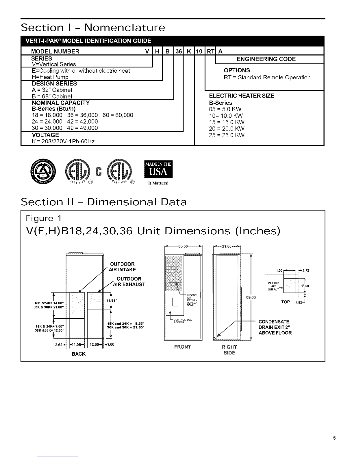
Section I - Nomenclature
MODEL NUMBER
SERIES
V=Vertical Series
E=Cooling with or without electric heat
H=Heat Pum
DESIGN SERIES
A = 32" Cabinet
B = 68" Cabinet
NOMINAL CAPACITY
B-Series (Btu/h)
18= 18,000 36=36,000 60=60,000
24 = 24,000 42 = 42,000
30 = 30,000 49 = 49,000
VOLTA GE
K = 208/230V-1 Ph-60Hz
V A
ENGINEERING CODE
OPTIONS
RT = Standard Remote Operation
ELECTRIC HEATER SIZE
B-Series
05 = 5.0 KW
10= 10.0 KW
15 = 15.0 KW
20 = 20.0 KW
25 = 25.0 KW
@
C
It Matters!
Section II- Dimensional Data
Figure 1
V(E,H)B18,24,30,36 Unit Dimensions (Inches)
t
18K &24K= 14.00"
30K & 36K= 21.00"
18K & 24K= 7,00"
30K &36K = 12.00"
2.62_
BACK
OUTDOOR
/ AIR INTAKE
OUTDOOR
JAIR EXHAUST
11.53"
18K and 24K = 8.25"
30K and 36K = 21,50 _
_1.00
FRONT
_21=00_
R_GHT
SiDE
0
TOP
CONDENSATE
DRAIN EXIT 2"
ABOVE FLOOR
4.82 _
Page 6

Figure 2
V(E,H)B42,
I
16!25
OUTDOOR
AIR
INTAKE
OUTDOOR
AIR
EXHAUST
=1200,
V(E,H)B42
BACK VIEW
49 Unit Dimensions (Inches)
JooI
2.5
i2'lL!
2.0--
--200
OUTDOOR OUTDOOR
AIR AiR
INTAKE EXHAUST
38o0G_
__DOOR ¢4R
RETURN
_ U SE....
pORT *
ACCESS
_CONTROL BOX
ACCESS
V(E,H)B49
BACK VIEW
CONDENSATE
DRAIN EXIT2"
ABOVEFLOOR
m
5=50
_NDOON AIN l
SUPPLY _ 14=50
_2=00
Figure 3
V(E,H)B60
1
30.00
"I'
12.00
J,
2.5 "_
i¸¸ i .......Ex.,o_,,lo
INDOOR
AIR SUPPLY OUTDOOR
mR
_,_usT
_'_ 15.00 "_,, €- 9.25"-_
V(E,H)B42
BACKVIEW
T
22.50
1
I
14.50
<'-2.50
.00
Unit Dimensions (Inches)
I _ INDOOR
AIR RETURN
1 24" X 30" NOM.
/
SERVICE PORT ACCESS
--CONTROL BOX ACCESS
<-'_ 30.50 -_'>
r_l
CONDENSATE DRAIN
EXIT 2" ABOVE FLOOR
Section III- Installation
The Vert-l-Pak was designed for installation in residential and light commercial applications. These instructions detail a
typical method of installation. Figure 4 shows the typical component location and airflow paths through the unit.
Page 7

Figure 4
Unit Configuration
INDOOR AIR SUPPLY
AUXILLARY ELECTRIC HEAT
OPTIONAL
SIDE AIR RETURN --..
RETURN AIR FILTER
INDOOR AIR
RETURN
CONTROL
BOX
REVERSING VALVE
(Heat Pump)
INDOOR BLOWER
OUTDOOR
EXHAUST
OUTDOOR
OUTDOOR
BLOWER
EXPANSION VALVE
OUTDOOR COIL
CONDENSATE DRAIN
1) INDOOR AND OUTDOOR AIR REQUIREMENTS
The indoorand outdoorairsystemsare designed tooperateat specified airflowratesand external staticpressures. The supply
and return air duct system pressure losses (including filter, louver/grille and registers) must not exceed the listed external
static pressures for either the indoor or outdoor air systems.
_i, CAUTION: Failure to adhere to indoor air and outdoor air requirements as listed inthe following sections will void unit
warranty.
A. Outdoor Air System
As acompletely self-contained system, the Vert-l- Pak unit requires an adequate supply of outdoor air to exchange heat from
the outdoor air coil. The outdoor air intake and discharge openings are located on the back side of the unit. The unit may
be installed where the outdoor air path runs through the wall of the building directly behind the unit or where the outdoor air
intake and discharge paths are ducted separately away from the unit. Figure 9 shows two typical ducted OA designs.
=_ CAUTION: To ensure proper operation, the outdoor air intake and discharge air paths must be free and unobstructed.
The two air paths must be situated toensure that the intake and discharge airdo not recirculate (also called short-circuit).
Page 8

Figure 5 VPBWP3 - 8/1 4 Wall Plenum
Outdoor Air
Sleeve
For Models
• VE/VH B18
•VE/VH B24
Outdoor Air Louver
Condensate
Drain Pipe
Finished Floor 18.50
Wail Framing
Brick or Other
Exterior Finish
Figure 6
VPBWP4 - 8/14 Wall Plenum
OUTDOOR
AIR WALL SLEEVE
For Models
,VENHB18
• VENH B24
• VE/VH B30
• VE/VH B36
CONDENSATE
DRAIN PIPE
OUTDOOR
FINISHED
FLOOR
WALL
FRAMING
BRICK OR OTHER EXTERIOR FINISHINC
Page 9

Figure 7 VPBWP5 - 8/14 Wall Plenum
CONDENSATE
DRAIN PIPE
FINISHED
FLOOR
OUTDOOR AIR
WALL SLEEVE
WALL FRAMING
For Models
• VE/VH B42
•VE/VH B49
OUTDOOR
BRICK OR OTHER
EXTERIOR FINISH
Figure 8 VPBWP6 - 8/14 Wall Plenum
OUTDOOR AIR
WALL SLEEVE
For Model
•VE/VH B60
CONDENSATE
DRAIN PIPE
OUTDOOR
AIR LOUVER
FINISHED FLOOR
WALL FRAMING
BRICK OR OTHER
EXTERIOR FINISH
Page 10

B. Ducted Condenser Air
For ducted outside air applications, the combined pressure losses of the intake and discharge air paths must not exceed
the external static capabilities of the system at the design airflow (See Table 3).
Outdoor Fan Performance
Table 1
ESP 0.0" 0.1" 0.2" 0.3"
VEB18 / VHB18 Outdoor 1160 1080 990 920
VEB24 / VHB24 Outdoor 1160 1080 990 920
VEB30 / VHB30 Outdoor 1300 1227 1131 lO26
VEB36 / VHB36 Outdoor 1600 1550 1480 1420
VEB42 / VHB42 Outdoor 2100 2000 1900 1800
VEB49 / VHB49 Outdoor 2400 2300 2200 2100
VEB60 / VHB60 Outdoor 2600 2550 2450 2350
Italics numbers indicate performance outside the required operating windo_
Bold figures indicate the standard rated airflow.
Figure 9 Typical Ducted Outside Air Configuration
INTAKE
OUTDOOR
AIRINTAKE
OUTSIDE
WALL
FLOOR
o..
CEILING
_ OUTSIDE
WALL
- OUTDOOR AIR
EXHAUST
EXHAUST
;................. iiiiii!!ili!!iii!ii!ii!i!iiii!ii
CEILING
BACK
OF
UNIT
OUTDOOR
OUTSIDE
A_R _
WALL
INTAKE I
I
I
OUTDOOR
FLOOR _ AIR EXHAUST
%
INTAKE
10
Page 11

C. Indoor-Air (Conditioned Supply Air) System
The VEB/VHB series unit may beapplied ineither afree return air configuration ora ducted return air configuration. The supply
air path is intended to be ducted. The design and construction ofthe indoor-air system must provide adequate air distribution
to ensure comfort levels throughout the structure.
The combined pressure losses ofthe return and supply air paths must not exceed the external static capabilities ofthe system
at the design airflow (See Table 2 below).
If the unit is installed in a closet behind a door and the return air louver or grille is directly opposite the unit RA opening, 2-
in. clearance isrequired between the front of the unit and the back side of the louver or grille. Ifthe louver or grille is located
elsewhere on the door so it is not directly in front of the RA opening, a minimum of 7-in. clearance is required between the
front of the unit and the back side of the door. The minimum "net free open area" required for the RA louver or grille is listed
in Table 2.
Indoor Fan Performance
Table 2
ESP Rated 0.1" 0.2" 0.3" 0.4" 0.5"
VEB18 / VHB18
VEB24 / VHB24
VEB30 / VHB30
VEB36 / VHB36
VEB42 / VHB42
VEB49 / VHB49
VEB60 / VHB60
Indoor
Indoor
Indoor
Indoor
Indoor
Indoor
Indoor
630
800
1000
1120
1400
1500
1800
85O
89O
1070
1220
1610
1610
2040
75O
8OO
1000
1120
1570
1570
1980
63O
720
94O
1050
1510
1510
1900
55O
650
830
990
1470
1470
1800
450
54O
720
86O
1400
1400
1750
IRAGrille Minimum Net
Free Open Area (Sq. In.)
25O
3OO
375
4OO
525
525
675
Italics numbers indicate performance outside the required operating window.
Bold figures indicate the standard rated airflow.
Indoor Airflow values were measured with wet coil.
Figure 10
Return Air Options
Front Free Return Front Ducted Return
NOTE: Ducted return air configuration requires field fabrication of a duct-mounted filter box.
11
Page 12

2) Electrical
I DANGER: Electrical shock hazard. Turn OFF electric power at the fuse box or service panel before making any I
electrical connections and ensure a proper ground connection is made before connecting line voltage. Failure to do
Iso can result in property damage, personal injury and/or death.
A. Grounding
,_. CAUTION: The unit must be electrically wired and grounded inaccordance with all state and local codes, national electric
code, and NFPA 70. Unit and controls will NOT operate unless properly grounded. Aground lug is provided for ground
connection. Use only approved copper wire and connectors from unit to service panel.
B. Power Supply
NOTE: Line voltage circuit is completelyfactory wired. Make allline voltage connections inside circuit breakerjunction box.
ThecircuitbreakersorfusesusedforbranchcircuitprotectionshouldbeULrecognized. Ifcircuit breakers are used, the circuit
breakerfor the compressorcircuit must havea UL HACRrating. Iffuses are used, thefuseforthecompressorcircuitMUST
be time delay type.
CAUTION: Units are dual voltage rated 208-230/1/60. The 24V control transformer must be connected for either 208V
or 240V power source for proper operation. Line voltage must not exceed 253V or go below 197V. The transformer
connection must be changed for 208V operation.
Depending on auxiliary heater size, unit must be supplied with 2 or 3 separate 208V or 240V circuits from structure's fuse
box or service panel. Each circuit is internally connected to a circuit breaker located in the unit control box located at the
front center of the unit. Refer to Table 4 and Table 5for required circuits and recommended wire size for each circuit.
Table 4
Minimum Circuit Maximum Fuse2or
= Model Compressor Amps Outdoor Fan Amps Indoor Fan Amps Ampacity Minimum Wire Size 1 Breaker Size Amps
u. _ V(E,H)B18 7.9 1.7 1.7 14.0 12 20
m_ V(E,H)B24 9.3 1.7 1.7 16.7 12 25
_- V(E,H)B30 15.0 2.2 1.8 22.8 10 30
t33
._= ,_ V(E,H)B36 17.9 3.0 2.5 27.9 8 40
oo'o V(E,H)B42 20.4 4.7 3.0 34.0 8 50
O V(E,H)B49 22.1 4.6 3.0 41.0 6 60
V(E,H)B60 32.1 4.6 3.1 49.0 6 60
Table 5
Heater Size Chassis Ckt#1 Ckt #1 Wire Ckt #1 Max. Ckt #2 &3 3 Ckt#2&3 3 Ckt #2 &3 3 Ckt#2& 3s
(KIN) Available Ckt #1 Amps Arn pacity Size _ Fuse 2 Amps Am pacity Wire Size _ Max. Fuse 2
Q 5.0 18/24 20 8 26.0 I O 30 N/A KVA N/A N/A
O.
10.0 18/24/30/36/42 416 52.0 6 60 N/A NVA N/A N/A
69 15,0 30/36/42/48 208 26.0 10 30 41.6 52.0 6 60
o_ 20,0 48/60 41 6 52.0 6 60 41.6 52.0 6 60
i
25,0 60 208 26.0 10 30 41.6 52.0 6 60
1 if wire is apptied at ambient greater than 30°C (86°F), consult Table 310-16 of the NEC (ANSI/NFPA 70) The ampacity of nonmetalic-sheathed cable (NM), trade
name ROMEX, shalt be that of 60°C (140°F) conductors, per the NEC (ANSI/NFPA 70)Article 336-30. If other than uncoated (non-plated), 60°C or 75°C (140°F or
167°F) insulation, copper wire (solid wire for 10 AWG and smalter, stranded wire for larger than 10 AWG) is used, consult applicable tables of the NEC (ANSI/NFPA 70).
2 Time-delay fuse.
3
Circuit #3 is only used for 25kw heater
Auxiliary
(Field
Heat Pump
(Field Wiring)
Heat Pump
Auxiliary
Heater#1
Ground
(Field
Auxiliary
Heater#2
(Field Wiring)
Line Voltage And Ground Connections
AUXILIARY HEATER #I
POWER WIRING
(FIELD WIRING)
= AUXILIARY HEATER #I
GROUND LUG •AUXILIARY HEATER #2
(FIELD WIRING) t60A, PARALLEL WIRING)
Unit Wiring with VPDB1 Distribution Block
12
Page 13

3) THERMOSTAT MOUNTING AND WIRING
A. Thermostat Location
Locate the thermostat about 5ft. above the floor in an area with good circulation at average indoor temperature.
Do not mount the thermostat where it may be affected by:
• Drafts or dead-air spots behind doors and in corners.
• Hot or cold air flow from ducts.
• Radiant heat from sun or appliances.
• Concealed pipes or chimneys.
• Unheated (uncooled) areas behind thermostat, such as an outside wall.
B. Thermostat Mounting and Wiring
The thermostat is a precision instrument and was carefully adjusted at the factory. Handle itcarefully.
_1_ CAUTION: Disconnect the power supply before beginning installation of the thermostat to prevent electrical shock
or equipment damage. Do not short across the thermostat terminals. This can burn out the thermostat anticipator.
All wiring for the thermostat circuit must comply with NEC, state and local codes. Use No. 20 AWG color-coded,
insulated (35°C minimum) wire. Ifthe thermostat is located more than 100 ft. from the unit (as measured along the
control voltage wires), use No. 18 AWG color-coded wires to avoid excessive voltage drop.
1. In replacement applications, check the existing thermostat wiring for cracked or frayed insulation. Replace any
wiring in poor condition. All wiring must comply with local codes and ordinances.
2. Run wiring (if necessary) to the location. Connect the wires to the terminals on the back of the thermostat. (See
Figure 11.)
3. Push the excess wire back through the hole and plug any opening with packing material to prevent drafts that may
affect thermostat performance.
4. Loosely secure the thermostat to the wall with screws through the two mounting holes in the middle ofthe thermo-
stat.
5.
6.
Level the thermostat. Tighten the two mounting screws.
Replace the thermostat cover.
C. Wire Thermostat Cable to Unit Terminal Strip
Attach thermostat wires to low-voltage terminal block on left side of control box.
Figure 1 1
Thermostat
Wiring
G R Y B W2
E
Compressor
V Reversing
m Valve
Auxiliary
Heat
E C
I
Common
Emergency
Heat
G R Y B W2 E X
13
Page 14

4) CONDENSATE DRAIN LINE
The condensate drain exits the unit 2" above floor level at the right side front corner of the unit. The condensate drain line
is already internally trapped therefore, no external condensate trap is required.
Install a condensate drain line of the same size as the drain fitting on the unit. PVC plastic pipe (3/4 in. I.D.) makes an ideal
condensate line (if local codes allow).
Run condensate drain line from unit to floor drain or outside perimeter of building per local codes.
The condensate line must have a minimum drop of 1/4" per running foot as it leaves the unit. When a horizontal run of 15
ft. or longer is required, it may be necessary to install a vent tee in the drain line near the unit or use a larger diameter drain
line. This is to eliminate air trapping and allow proper condensate drainage.
Heat pumps generate condensate during both cooling and heating modes. Condensate drain line must be
protected from freezing to prevent condensate from backing up in unit during freezing outdoor conditions. See
page 4 for Cold Climate accessories.
NOTE: If the unit is to be installed in an attic or furred space where damage may result from condensate overflow, it may
be necessary to provide a field-supplied secondary drain pan. Always refer to local and national codes.
INSTALLATION - FINAL CHECKLIST
[] Is power to the unit ON?
[] Are circuit breakers/power
disconnect inside of the unit
ON?
[] Is ductwork sealed for
airtight
an
fit?
[]
Is the condensate drain line
installed and run to an
appropriate disposal site.?
Test Run
Test run in Heating, Cooling, and Emergency Heat mode as follows:
[] Is the thermostat level and
properly installed?
[] Is the heat anticipator indicator
set to the correct setting.?
a.
b.
C.
d.
Set fan control to ON. Iffan runs, return control toAUTO setting. This verifies fan is working properly.
Set system control from OFF to COOL. Lowertemperature selector to 50°For lower. The compressor should energize
and cool air should flow from room registers. Once cooling test is complete, return system control to OFF setting.
Wait 5 minutes.
Set system control to HEAT and raise temperature selector to 80°F or higher. Compressor should energize, andwarm
air should flow from room registers.
Set system control to EM HEAT (Emergency Heat). Compressor should turn offand warm air should continue to flow
from the registers. (This step is for heat pumps only.)
NOTE: During EM HEA Toperation, temperature of airflowing from room registers may be slightly warmerthan during
normal HEA Tmode operation.
Leave this manual with owner or user of equipment.
After 72 hours of operation, the unit will achieve full rated operating performance.
14
Page 15

Section IV - OWNER'S MANUAL AND OPERATING
INFORMATION
IDENTIFYING YOUR SYSTEM
Take the time to familiarize yourself with the type of system you have. This knowledge will be of use in understanding the
basic operation of your unit.
A self-contained unit, like the Vert-l-Pak, has all of its major components in one cabinet located inside your home. The unit
does not have a separate outdoor unit like a traditional "split-system" air conditioner or heat pump. Figure 4 shows the
location of the major components inside the cabinet.
The product model and rating data label is affixed tothe unit front panel and provides the necessary information for specific
identification of the unit. You should familiarize yourself with the model and serial numbers listed on the label.
IMPORTANT FACTS
To better protect your investment and to eliminate unnecessary service calls, familiarize yourself with the following facts:
Your system should never be operated without a clean air filter properly installed. A dirty, clogged air filter will increase
operating costs and shorten the life of the unit. The air filter should be replaced as it becomes dirty.
Supply-air and return-air registers should not be blocked. Restricted airflow reduces the efficiency and life span of your unit.
For your system to function properly, it MUST have a constant supply of outdoor air to the outdoor air coil located inside
the unit. The outdoor-air intake and exhaust openings are located on the back side of the unit. Familiarize yourself with the
outside air openings on the building and check toensure that they are not obstructed.
Thermostat
Your multipurpose indoor thermostat is the control center for your comfort system. You should familiarize yourself with its
proper operation. Attempting to control the system by other means -for instance, switching the electrical supply power ON
and OFF - may cause damage to the unit.
With some thermostats, increasing the HEAT mode temperature set point more than 2°F may cause the auxiliary electric
heaters to operate to satisfy the call for heating. To minimize energy costs, do not increase the HEAT mode temperature
set point by more than 2°F at a time.
Depending on the design of your home and its ventilation ductwork and registers, areas of warm or cool air may develop
throughout the home. Operating the unit with the fan switch "ON" increases air mixing throughout the home and reduces
temperature variations within the home.
Dehumidification
During the cooling season, the Vert-l- Pak also dehumidifies the air inthe home while is it cooling the air. After a few minutes
of operation, water should run freely from the condensate drain line extended to the outside of your home. tf condensate is
not running from the drain line, check to be sure that the drain hose or pipe is properly connected to the drain fitting located
on the bottom of the unit which is accessible from beneath the home. Check the drain line periodically during the cooling
season to ensure the condensate is running freely from outside the home and draining away from the home's foundation.
(Note: in lower humidity climates, the indoor air may be too dry to generate condensate during the cooling mode.)
Heat Pump
If you are afirst-time owner of an all-electric heat pump, the operating characteristics of the system may be different than
you are accustomed to as compared to conventional electric resistance, gas or oil furnaces. Air entering a conventional
furnace at 60°F may be warmed 60° to 100°F. The supply air leaving the registers would then be between 120°and 160°F
depending on the system. A heat pump warms the same 60°F air 20° to 30°F. The supply air leaving the registers would
then be between 80° and 90°F. This air may feel cool because it is slightly less than your body temperature. However, it
is sufficiently warm to keep you comfortable and is adding heat to your home. Aheat pump will run for much longer periods
of time than aconventional furnace. This longer operational time is normal for all heat pumps and is saving you energy in
comparison to many conventional furnaces. On days with outdoor temperatures below40°F, it isnormal for the heat pump
15
Page 16

to run for extended periods oftime and may be assisted by the auxiliary electric resistance heating elements. Once you
understand the operation of your new heat pump, you will appreciate its constant, even heat and lower energy consumption.
Heat Mode Operation
During the heat mode ofoperation, frost or ice may build up on the outdoor-air coil after operating for extended periods during
particularly cool and humid weather. When this occurs, your heat pump senses this condition and goes through a defrost
cycle. During the defrost cycle, the outdoor-air blower is turned off, and the reversing valve reverses the flow of refrigerant
through the outdoor-air coil so it is heated and the frost or ice melts. You may notice the defrost cycle inside your home
by a faint click and hissing sound and aslight change in the sound created by the blower as the defrost cycle begins and
ends. During the defrost cycle, you may also notice that the air is quickly heated as the defrost cycle ends. Outside the
home, a cloud of water vapor created by the melting frost or ice may be visible as it is exhausted. This is normal and keeps
the unit working efficiently. Do not be alarmed!
Condensate
The heat pump may generate condensate during both the cooling and heating modes of operation. For proper operation,
a condensate drain line must be extended from the drain fitting on the right side of the unit to the perimeter of the home
orto a proper drain location. The drain line must be sloped towards the outside of the home or drain location and be protected
from freezing.
NOTE: In order for condensate to drain freely, the unit must be installed level.
OPERATING THE VERT-I-PAK
THERMOSTAT OPERATION
The operation of the system iscontrolled by the indoor thermostat. Most thermostats have 3controls: atemperature control
selector, a FAN control, and a SYSTEM or MODE control. (See Figure 3.)
Typical Heat/Cool Thermostat
The temperature control is a selector or set of buttons that allows you to establish the degree of temperature that you wish
to maintain for your personal comfort. Some thermostats have two temperature control selectors: one for setting the
temperature desired during the cooling cycle, and one for setting the heating operation temperature.
Typical settings are 78°F for cooling and 68°F for heating.
Fan Control
The FAN control offers two options for controlling the indoor-air blower: AUTO and ON. When the FAN control is set to
AUTO, the blower will operate only while the thermostat operates the cooling or heating equipment. When the FAN control
is set to ON, the blower will operate continuously - regardless of whether cooling or heating equipment is operating. This
setting allows for continuous air circulation and filtration.
16
Page 17

System Control
The SYSTEM or MODE control on your thermostat offers the following selections: COOL, OFF, HEAT, and EM HEAT.
Neither the cooling nor heating equipment will operate when the SYSTEM orMODE control isset to OFF. With the SYSTEM
or MODE control set to COOL, your unit will operate in cooling mode. With the SYSTEM or MODE control set to HEAT,
your unit will operate in heating mode.
Auxiliary Heating
Your system also includes anauxiliary electric heating source. The SYSTEM or MODE control options HEAT and EM HEAT
provide convenient selection between the two heating appliances. The heat pump will operate when SYSTEM or MODE
control is set to H EAT. The auxiliary electric heater may also be used on cold days to supplement heat pump heating. With
the SYSTEM or MODE control set to EM HEAT, the heat pump is turned offand the auxiliary electric heat is activated. The
unit is now operating as an electric furnace.
On heat pump systems, the wall thermostat regulates the use of auxiliary electric heat to maximize energy efficiency and
your home comfort.
COOLI NG CYCLE
When operating in the cooling cycle, your unit will operate until the indoor temperature is lowered to the level you have
selected on the indoor thermostat. On extremely hot days, your unit will operate for longer periods of time and have shorter
"off' periods than on moderate days.
The following are typical conditions that add extra heat and/or humidity to your home and force your cooling unit to work
longer to keep your home comfortable:
• Entrance doors are frequently opened and closed.
• Laundryappliancesare being operated.
• Ashoweris running.
• More than the usual number of people are present in the home.
• More than the normal number of electric lights are in use.
• Drapes or blinds are open on the sunny side of the building or home.
HEATING CYCLE
With the SYSTEM control of your indoor thermostat set to HEAT, the heating section of your home comfort system will
operate until room temperature is raised to the level you have selected. Of course, the heating unit will have to operate for
longer periods to maintain acomfortable environment on cooler days and nights than on moderate ones. When the demand
is greater than the capacity of the heat pump alone, the auxiliary electric heaters will supplement the heat pump.
I NOTE: Non-Heat Pump models use a single stage heat thermostat. When a demand for heat is made, I
I
these units will use the electric heat strip heat immediately.
I
DEFROST CYCLE
When your heat pump isproviding heat to your home and the outdoor temperature drops below45°F, moisture may begin
tofreeze on the surface of the outdoor-air coil. If allowed to build up, this ice would impede airflow across the coil and reduce
the amount of heat absorbed from outside air. To maintain energy-efficient operation, your heat pump has an automatic
defrost cycle.
The defrost cycle will occur only if ice is sufficient to interfere with normal heating operation. After ice is melted from the
outdoor-air coil, the unit automatically switches back to normal heating mode.
Do not be alarmed ifsteam orfog appears atthe outdoor-air exhaust during the defrost cycle. Water vapor from the melting
ice may condense into a mist in the cold outdoor air.
17
Page 18

PERFORMING ROUTINE MAINTENANCE
With the proper maintenance and care, your system will operate economically and dependably. Maintenance can be
accomplished easily by referring to the following directions. However, before performing any maintenance, consider these
important safety precautions:
,A WARNING: Electrical Shock Hazard. Before attempting any service work or routine maintenance, turn offall electrical
connections to the unit. Failure to do so may result in property damage, personal injury and/or death.
CAUTION: Although great care has been taken to minimize sharp edges in the construction of your unit, be extremely
careful when handling parts or reaching into the unit.
REPLACE AI R FI LTER
A dirty air filter reduces the efficiency of yourVert-l-Pak and allows lint and dirt to accumulate on the indoor-air coil. Lint and
dirt on the indoor-air coil can damage your unit and void the warranty. The air filter should bereplaced as it becomes dirty.
To replace the filter (front air return units):
1. Slide the filter to the right until it clears the filter rails (See Figure 12).
2. Remove the filter.
3. Install new disposable filter.
CAUTION: Do not operate your system without a filter in place, nor block the front of the unit return air opening.
Figure 1 2 Fi Iter Replacement
Filter Rails
Air Filter --_
To remove the filter,
slide it to the right side
of the unit as shown.
Removingthe Filter From the Front Filter Rack
18
Page 19

INSPECT AND CLEAN INDOOR-AIR COIL
Eventually, minor amounts of lint and dirt may pass through the filter and collect on the indoor-air coil. These minor
accumulations can be carefully vacuumed away with abrush attach ment on a vacuum cleaner. Care must be taken to avoid
bending the aluminum fins on the coil. Bent fins should be straightened using a special fin tool available from most HVAC
service technicians.
INSPECT OUTDOOR-AIR INTAKE AND EXHAUST
The unit's outdoor-air intake and outdoor-air exhaust paths must remain clear. Check the OA exhaust frequently. Keep it
free of all debris, snow, or ice. The OA intake should also be kept free ofobstructions. Blocking the OA exhaust or OA inta ke
opening will reduce the efficiency of your unit, could damage it, and void your warranty.
INSPECT AND CLEAN CONDENSATE DRAIN
The condensate drain must be routed to a suitable drainage area. Check the unit condensate drain periodically. Keep itfree
of anything that may block or impede the flow of condensate water. Ifthere isany accumulation offoreign matter inthe drain
pipe, it should be removed and cleaned. The entire drain line must be protected from freezing.
19
Page 20

Use Factory Certified Parts.
FRIEDRICH AIR CONDITIONING CO.
Post 0trice Box 1540 San Antonio, Texas 78295-1540
4200 N. Pan Am Expressway San Antonio, Texas78218-5212
(210) 357-4400 Fax (210) 357-4480
www.friedrich.com
Printed in the U.S.A. 920-164-00 (10-03)
 Loading...