

Friedrich VPBWP3-8, VPBWP4-14, VPBWP3-14, VPBWP4-8, VPBWP5-8 Installation & Operation Manual
...
Vert-I-PakBSeries
SinglePackageVerticalAirConditioningSystem
18,000I 24,000I 30,000I 36,000I 42,000I 49,000I 60,000Btu/h
Installation&OperationManual
929-164-00 (10-03)

TABLE OF CONTENTS
I.
I1.
III.
1.
.
.
.
IV.
Page
Safety Considerations ...................................................................................................... 3
General Recommendations .............................................................................................. 3
Unpacking and Inspecting the Unit ................................................................................... 3
Supplies Needed for Installation ....................................................................................... 3
Accessories ..................................................................................................................... 4
General Specifications
Model Number Identification Guide ................................................................................... 5
Dimensional Data
V(E,H)B18,24,30,36 Unit Dimensions .............................................................................. 5
V(E,H)B42,49 Unit Dimensions ........................................................................................ 6
V(E,H)B60 Unit Dimensions ............................................................................................ 6
Installation
Indoor and OutdoorAir Requirements
A. OutdoorAir System .......................................................................................... 7-9
B. Ducted CondenserAir ........................................................................................ 10
Outdoor Fan Performance .................................................................................. 10
C. IndoorAir (Conditioned SupplyAir) System ........................................................ 11
Indoor Fan Performance ...................................................................................... 11
Electrical
A. Grounding .......................................................................................................... 12
B. Power Supply .................................................................................................... 12
Thermostat Mounting and Wiring
A. Thermostat Location .......................................................................................... 13
B. Thermostat Mounting & Wiring .......................................................................... 13
C. Wire Thermostat Cable to UnitTerminal ............................................................. 13
Condensate Drain Line ................................................................................................... 14
Installation - Final Checklist .......................................................................................... 14
Test Run ....................................................................................................................... 14
Owners Manual & Operating Information
Identifying your System ................................................................................................. 15
Important Facts ............................................................................................................. 15
Operating the Vert-l-Pak ................................................................................................. 16
Thermostat Operation .................................................................................................... 16
Cooling Cycle ................................................................................................................ 17
Heating Cycle ................................................................................................................ 17
Defrost Cycle ................................................................................................................. 17
Performing Routing Maintenance ................................................................................... 18
Replace the Air Filter ..................................................................................................... 18
Inspect and Cleaning the lndoorAir Coil ........................................................................ 19
Inspect the OutdoorAir Intake and Exhaust ................................................................... 19
Inspect and Clean the Condensate Drain ....................................................................... 19

SAFETY CONSI DERATIONS
Improper installation, adjustment, alteration, service, maintenance, or use can cause explosion, fire, electrical shock, orother
conditionswhich maycause personal injuryor propertydamage. Consulta qualified installer, service agency, oryourdistributor
ordealer for information and assistance. Thequalified installer oragency must usefactory-authorized parts oraccessories when
modifying this product. Refer to the individual instructions packaged with the parts or accessories when installing.
Follow all safety codes. Wear safety glasses and work gloves. Read these instructions thoroughly and follow all warnings or
cautions attached to the unit. Always install units inaccordance with local building codes, the National Electric Code (NEC),
and the Installation Standards, Warm Air Heating and Air Conditioning Systems ANSI/NFPA 90B for special installation
requirements.
GENERAL RECOMMENDATIONS (DO'S AND DON'T'S)
• DO read the instructions completely before installation.
• DO take time to perform a quality installation.
• DO install drain heater accessory if outdoor design temperature is 15°F or below.
• DO NOT obstruct or restrict indoor or outdoor air paths.
• When using flex duct: DO install properly. DO NOT crush or make sharp bends in flex duct, use only gradual bends.
• DO tape and seal all duct joints.
• DO check the indoor conditioned air duct system static pressure losses. It should notexceed those listed inTable 2.
Consult your dealer ordistributor for more information.
• When designing indoor supply systems, DO NOT reduce air intakes or discharge sizes.
• DO insulate ALL conditioned air duct system components.
• DO NOT locate room thermostat near conditioned air diffusers.
• DO locate thermostat on an interior wall.
• DO check that condensate drain line drains freely.
• DO NOT let debris fall and collect in indoor or outdoor blowers.
• DO NOT drill into unit (except for 1 in. flanges for ducted return units). This could cause a refrigerant leak.
• DO handle unit with care.
• DOprovide minimum installation and service clearances.
• DO build closet so that unit may be removed if necessary.
• DOfollow all guidelines for indoor and outdoor air system.
• DONOTsubstituteanycomponentswithoutcheckingwithyourdealerordistributor. Ifyoudosubstitute,getapproval
in writing. Substitutions without approval void unit warranty.
• DO NOT guess, consult your dealer or distributor if any portion of the installation procedure is unclear.
UNPACK AND INSPECT UNIT
Remove shipping protection and pallet from unit and inspect for damage. Be sure to check for concealed internal shipping
damage. Do not install a damaged unit.
SUPPLIES NEEDED FOR INSTALLATION
The following items are required to install unit.
• Adhesive, aluminum duct tape.
_t, CAUTION: Incorrect type of duct tape may be afire hazard. A failure to follow this warning could result in a fire and
personal injury or death.
• 6-conductor thermostat cable (20 gage wire minimum).
_i, CAUTION: Do not use thermostat wire with less than the recommended number of conductors.
Supplies
Supplies
Supplies
Supplies
Supplies
to connect indoor air (conditioned air supply) duct to unit.
to connect power to unit.
to connect outdoor-air duct to unit.
to connect condensate drain line.
to connect low-voltage thermostat to unit.

MODEL # DESCRIPTION PHOTO
Telescoping wall plenums adjust to exact wall depth. Models with -8 suffixes adjust 4 1/2" - 8" deep; -14 models adjust 8" - 14".
WALL SLEEVE- Used when chassis is positioned against an exterior wall for outdoor air infiltration.
VPBWP3-8
VPBWP3-1 4
VPBWP4-8
VPBWP4-1 4
VPBWP5-8
VPBWP5-1 4
VPBWP6-8
VPBWP6-1 4
Recommended for use with 18,000 and 24,000 Btu/h units.
DIMENSIONS: 18 1/4" high x 28 1/4" wide.
CUTOUT DIMENSIONS: 18 1/2" high x 28 1/2" wide.
Recommended foruse with 18,000, 24,000, 30,000 and 36,000
Btu/h units.
DIMENSIONS: 24 1/4" high x 30" wide.
CUTOUT DIMENSIONS: 24 1/2" high x 30 1/4" wide
Recommended for use with 42,000 and 49,000 Btu/h units.
DIMENSIONS: 24 1/4" high x 38" wide.
CUTOUT DIMENSIONS: 24 1/2" high x 38 1/4" wide.
Recommended for use with 60,000 Btu/h units.
DIMENSIONS: 34 1/4" high x 40" wide.
CUTOUT DIMENSIONS: 34 1/2" high x 40 1/4" wide.
ARCHITECTURAL LOUVER- Extruded aluminum outdoor louver that attaches to the wall sleeve or outside
of the building.
VPAL3
VPSC3
Architectural louver for VPBWP3 plenums.
Custom colored architectural louver for VPBWP3 plenums.
VPAL4 Architectural louver for VPBWP4 plenums.
VPSC4 Custom colored architectural louver for VPBWP4 plenums.
VPAh5 Architectural louver for VPBWP5 plenums.
VPSC5 Custom colored architectural louver for VPBWP5 plenums.
VPAL6
VPSC6
RT3
VPDB1
Architectural louver for VPBWP6 plenums.
Custom colored architectural louver for VPBWP6 plenums.
THERMOSTAT Digital two-stage, manual changeover
thermostat for B Series heat pumps only. For nonheat pump
models, use RT1.
DISTRIBUTION BLOCKAIIows B Series Vert-t-Paks to be
connected to a single-point power source. Block and wiring
is entirely contained within the unit electrical control box.
COLD CLIMATE KITS- The following kits are to be applied in climates where the outdoor design
temperature is 15°F or below.
VPDPH5
VPDPH6
Outdoor coil drain pan/line heater for 18,000 - 36,000 Btuh units.*
Outdoor coil drain pan heater for 42,000- 60,000 Btuh units.
*No additional electrical service is required for these kits.
4
Section I - Nomenclature
MODEL NUMBER
SERIES
V=Vertical Series
E=Cooling with or without electric heat
H=Heat Pum
DESIGN SERIES
A = 32" Cabinet
B = 68" Cabinet
NOMINAL CAPACITY
B-Series (Btu/h)
18= 18,000 36=36,000 60=60,000
24 = 24,000 42 = 42,000
30 = 30,000 49 = 49,000
VOLTA GE
K = 208/230V-1 Ph-60Hz
V A
ENGINEERING CODE
OPTIONS
RT = Standard Remote Operation
ELECTRIC HEATER SIZE
B-Series
05 = 5.0 KW
10= 10.0 KW
15 = 15.0 KW
20 = 20.0 KW
25 = 25.0 KW
@
C
It Matters!
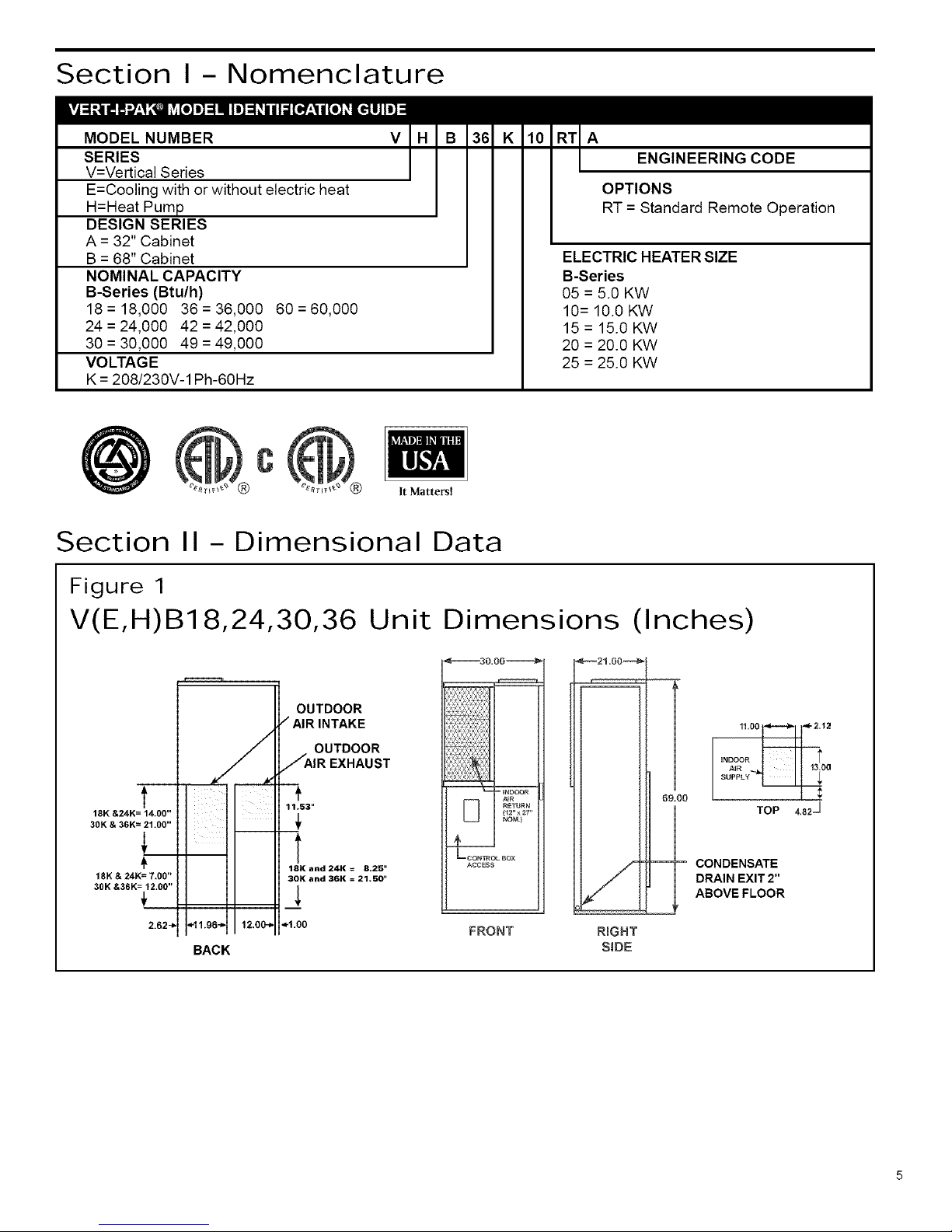
Section II- Dimensional Data
Figure 1
V(E,H)B18,24,30,36 Unit Dimensions (Inches)
t
18K &24K= 14.00"
30K & 36K= 21.00"
18K & 24K= 7,00"
30K &36K = 12.00"
2.62_
BACK
OUTDOOR
/ AIR INTAKE
OUTDOOR
JAIR EXHAUST
11.53"
18K and 24K = 8.25"
30K and 36K = 21,50 _
_1.00
FRONT
_21=00_
R_GHT
SiDE
0
TOP
CONDENSATE
DRAIN EXIT 2"
ABOVE FLOOR
4.82 _

Figure 2
V(E,H)B42,
I
16!25
OUTDOOR
AIR
INTAKE
OUTDOOR
AIR
EXHAUST
=1200,
V(E,H)B42
BACK VIEW
49 Unit Dimensions (Inches)
JooI
2.5
i2'lL!
2.0--
--200
OUTDOOR OUTDOOR
AIR AiR
INTAKE EXHAUST
38o0G_
__DOOR ¢4R
RETURN
_ U SE....
pORT *
ACCESS
_CONTROL BOX
ACCESS
V(E,H)B49
BACK VIEW
CONDENSATE
DRAIN EXIT2"
ABOVEFLOOR
m
5=50
_NDOON AIN l
SUPPLY _ 14=50
_2=00
Figure 3
V(E,H)B60
1
30.00
"I'
12.00
J,
2.5 "_
i¸¸ i .......Ex.,o_,,lo
INDOOR
AIR SUPPLY OUTDOOR
mR
_,_usT
_'_ 15.00 "_,, €- 9.25"-_
V(E,H)B42
BACKVIEW
T
22.50
1
I
14.50
<'-2.50
.00
Unit Dimensions (Inches)
I _ INDOOR
AIR RETURN
1 24" X 30" NOM.
/
SERVICE PORT ACCESS
--CONTROL BOX ACCESS
<-'_ 30.50 -_'>
r_l
CONDENSATE DRAIN
EXIT 2" ABOVE FLOOR
Section III- Installation
The Vert-l-Pak was designed for installation in residential and light commercial applications. These instructions detail a
typical method of installation. Figure 4 shows the typical component location and airflow paths through the unit.
 Loading...