

Page 1

INSTALLATION
INSTRUCTIONS
WALL PLENUM AND LOUVER
WALL PLENUM
For Use With Vert-I-Pak
NOTE: These instructions apply to Vert-I-Pak A Series Units ONLY. Refer to
Chassis Installation/Operation Manual for additional information.
Please read these instructions completely
before attempting installation.
VPAWP1
VPAWP2
VERY IMPORTANT!
YOUR WALL PLENUM WILL WORK ONLY IF INSTALLED CORRECTLY. TAKE NOTICE TO
INSTALL IT IN THE CORRECT ORIENTATION AS SHOWN IN THE ILLUSTRATIONS.
Step 1: Included Parts
There are two parts to a Wall Plenum:
A) 1-Outside Assembly (Part A)
B) 1-Inside Assembly (Part B)
Step 2: Field Supplied Parts:
Caulk, Attachment screws and Flashing
are field supplied. Silicone caulk is
recommended.
VPAWP1 adjusts for walls 5.5 - 8.0" thick.
VPAWP2 adjusts for walls 8 - 14.0" thick.
45° Drip
Ledge
PART A CORRECT ORIENTATION:
●●
●
LOUVER ATTACHMENT
●●
FLANGES TOWARD THE
BUILDING OUTSIDE, 45°
DRIP LEDGE AT THE BOTTOM.
Part A
Outside
Plenum
PART B CORRECT ORIENTATION:
● LARGE OPENING TO BOTTOM
3/4" FLANGE TOWARD THE INSIDE
OF THE BUILDING.
Part B
Inside
Plenum
Both installations are similar.
Flashing
Caulk
Header materials /
wall studs
1" –3" Screws to
attach the plenum
assembly to the wall
studs
Shim
920-069-04 (7/01)
Page 2
Step 3: Measure and frame out the outside wall plenum opening
Measure your outside wall as shown in the
illustration. Cut, frame, and square rough
opening. The Wall plenum has a 3/4" break
all the way around to cover the rough cut
opening or required shim.
IMPORTANT: THE WALL PLENUM IS NOT
DESIGNED TO CARRY STRUCTURAL
LOADS. A PROPER HEADER OPENING
MUST BE BUILT INTO THE ROUGH
OPENING. THE PLENUM REQUIRES
FLASHING, SHIM AND CAULK FOR A
WEATHER-RESISTANT INSTALLATION.
IT IS THE RESPONSIBILITY OF THE
CONTRACTOR TO PROPERLY INSTALL
THE PLENUM AND MEET BUILDING
CODE REQUIREMENTS.
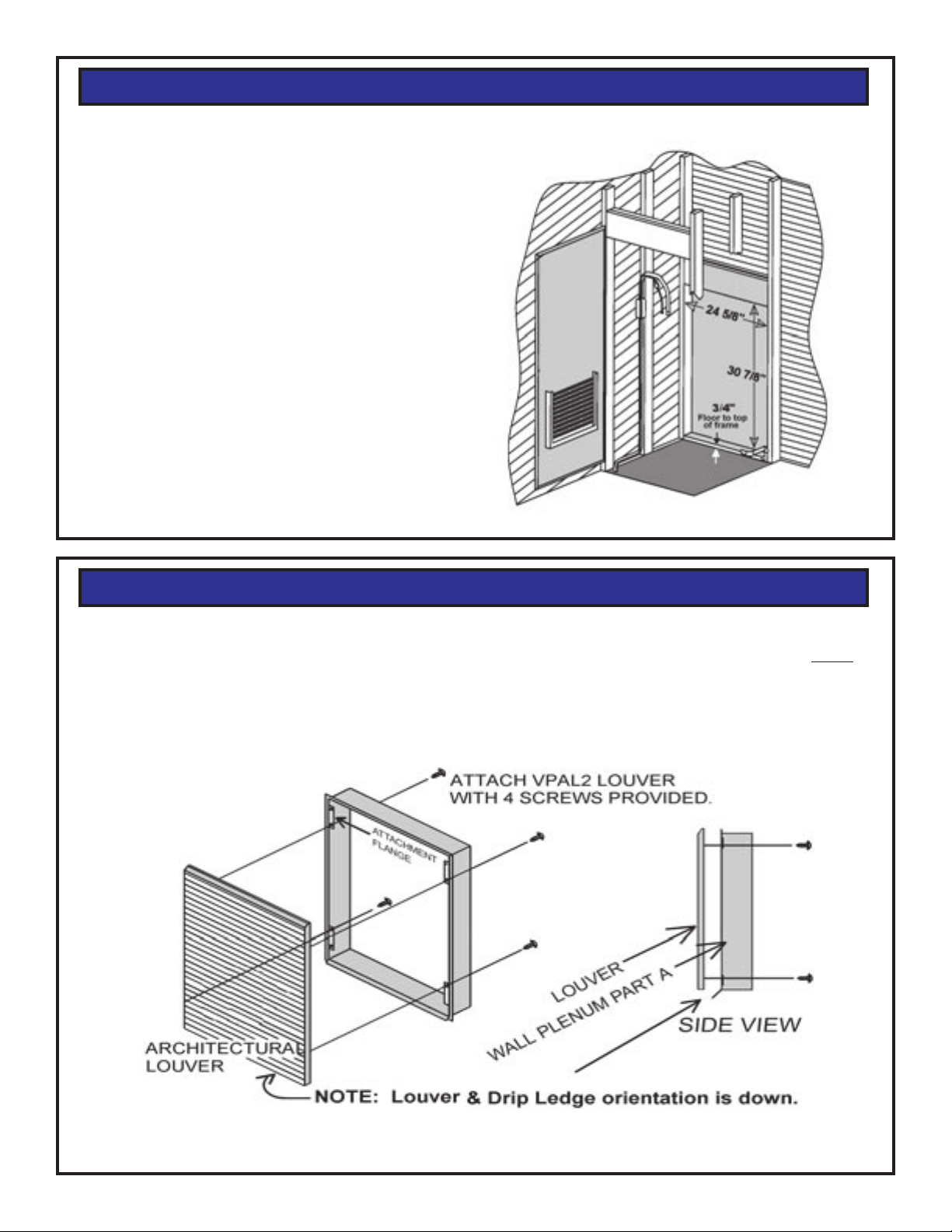
Step 4: Install Architectural Louver on the Outside Plenum
The VPAL2 Architectural Louver is best installed onto the Outside Plenum (Part A) prior
NOTE:
to Wall Plenum installation. Louver installation is easier at this point, and it will help keep
the Wall Plenum square during installation.
Page 2
Page 3

Step 5: Plenum Installation
Note: Proper header and wall penetration must conform to all
national and local building codes.
Proper Flashing
Proper Caulking
Caulk all 8
flange corners
Proper Header
Inside Wall Plenum
(Part B)
Architectural louver VPAL2
mounted on the outside wall
plenum (Part A)
Outside Wall
Proper Flashing
Proper Caulking
After the rough cut opening is prepared, you are ready to assemble the two wall plenum parts.
Before caulking and permanent attachment, dry fit the outside plenum into the rough opening
and check for fit and level. Caulk (silicone recommended ) the parts well and insert them into
the wall as shown.
A) Apply caulk and insert Outside Part A into the hole.
B) Apply caulk and insert Inside Part B into Part A. Be sure that Part A does not back out
of the wall hole.
IMPORTANT: DO NOT RUN SCREWS THROUGH THE TOP OR
BOTTOM OF THE WALL PLENUM.
Page 3
Page 4

Step 6 - Adjust the Divider
Adjustment A:
Ensure that the plenum divider is located
in the proper slot. The divider has a label
indicating the proper placement as follows:
Top Position: 18,000 Btuh models prior
to the E-suffix.
Middle Position: All E-suffix Vert-I-Pak
Models 9,000, 12,000, and 18,000
Btuh.
Lower Position: 9,000 and 12,000
Btuh models prior to the E-suffix.
NOTE: The plenum is shipped with the
divider in the middle position for
all E-suffix models.
A
Adjustment B
Loosten the two screws located on the top
side of the divider. Slide the top part of
the divider toward the outside until the
sealing strip makes contact with the
outdoor louver. Tighten the divider screws
to complete the adjustment.
NOTE: Let the caulk cure completely
before installing the chassis.
This completes the plenum
installation.
B
FRIEDRICH AIR CONDITIONING CO.
Post Office Box 1540 • 4200 N. Pan Am Expressway • San Antonio, Texas 78295-1540 • (210) 357-4400 • FAX (210) 357-4480
Page 4
920-069-04 (7/01)
 Loading...