

Page 1
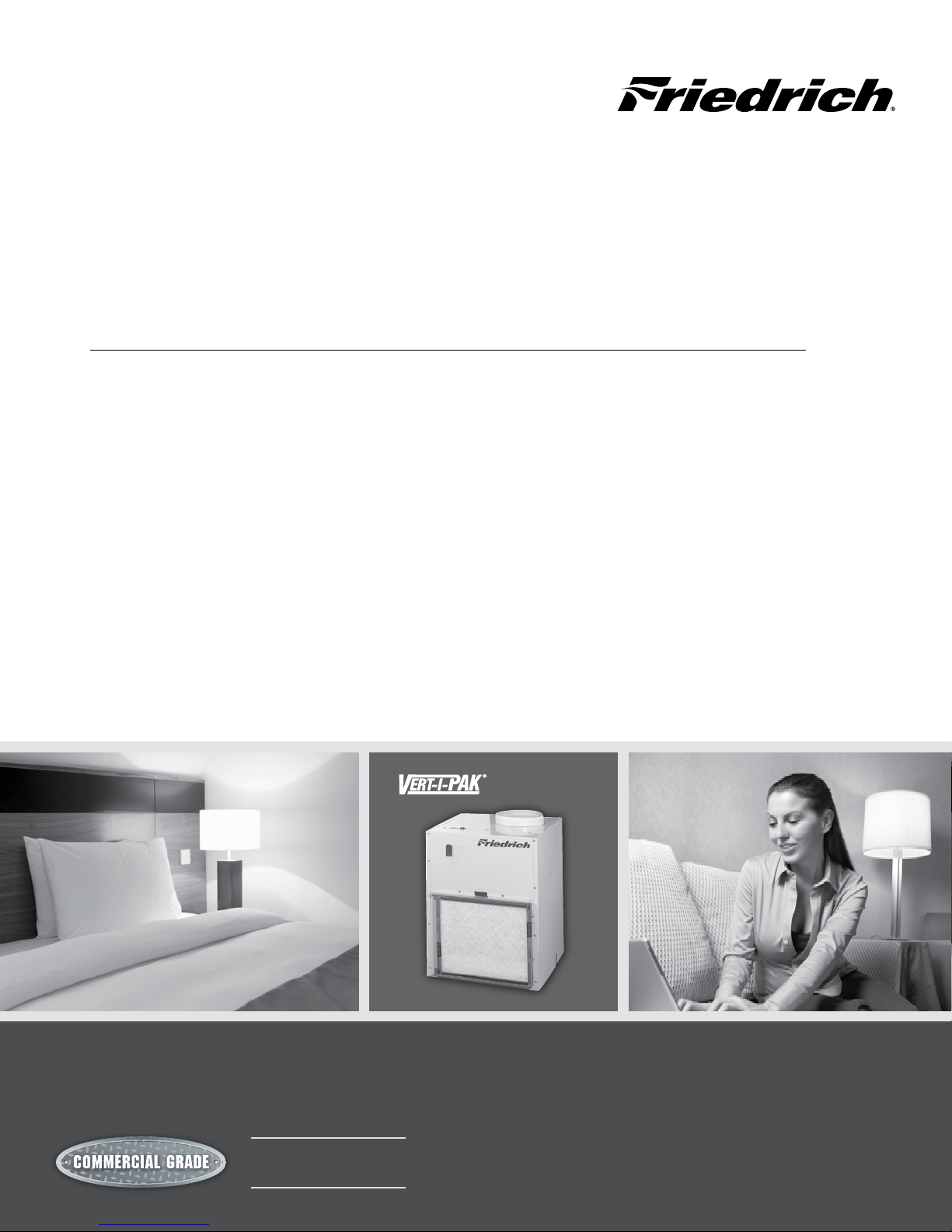
Product Profile
SINGLE PACKAGE VERTICAL AIR CoNdITIoNERS ANd HEAT PUMPS
Completely self-contained unit.
No outside condensing unit, eliminating the need for
external electrical wiring, landscaping and vandalism
barriers.
Unit is wired and charged at the factory.
No refrigerant lines running from oor to oor.
All units are shipped with return air lter installed.
An individual packaged unit can be used to heat or
cool multiple rooms.
Cabinets are fully insulated for improved sound
characteristics and unit performance.
Safety power disconnect.
Remote thermostat-ready 24-volt transformer.
Complete line of accessories.
Smaller closet dimensions.
Compact and lightweight– weighs as little as 125 lbs.
Unique free-oating chassis.
Ten inch crimped and beaded duct-collar ready to
attach ex-duct.
Easy to connect right, left or rear drain connection.
Easy to install front, left or right hand into closet.
Q U A L I T Y
www.friedrich.com
HEAT PUMP
ELECTRIC HEAT
Page 2
Chassis Specications
VEA/VHA09-24
VEA09K VEA12K VEA18K VEA24K VHA09K VHA12K VHA18K VHA24K
C O O L I N G D A T A
Cooling Btu/h 9500/9300 11800/11500 17500/17300 24000 9500/9300 11800/11500 17500/17300 23500
Cooling Power (W) 880 1093 1882 2526 905 1124 1882 2474
EER 10.8 10.8 9.3 9.5 10.5 10.5 9.3 9.5
Sensible Heat Ratio 0.74 0.72 0.70 0.70 0.74 0.72 0.70 0.70
H E A T P U M P D A T A
Heating Btu/h N/A N/A N/A N/A 8500/8300 10600/10400 17000/16800 22500
COP @ 47°F N/A N/A N/A N/A 3.0 3.2 3.0 3.0
Heating Power (W) N/A N/A N/A N/A 830 971 1560 2200
Heating Current (A) N/A N/A N/A N/A 4.4/4.9 5.5/6.1 7.5/8.2 11.4
E L E C T R I C A L D A T A
Voltage (1 Phase, 60 Hz) 230/208 230/208 230/208 230/208 230/208 230/208 230/208 230/208
Volt Range 253-198 253-198 253-198 253-198 253-198 253-198 253-198 253-198
Cooling Current (A) 4.1/4.3 4.9/5.3 8.4/9.0 11.2/12.4 4.2/4.4 5.0/5.5 8.4/9.2 11.2/12.4
Amps L.R. 21 21 42 68 21 21 42 68
Amps F.L. 3.7 4.5 7.5 10.2 3.7 4.5 7.5 10.2
Indoor Motor (HP) 1/4 1/4 1/4 1/4 1/4 1/4 1/4 1/4
Indoor Motor (A) 1.2 1.2 1.2 2 1.2 1.2 1.2 2
Outdoor Motor (HP) N/A N/A N/A 1/4 N/A N/A N/A 1/4
Outdoor Motor (A) N/A N/A N/A 2 N/A N/A N/A 2
A I R F L O W D A T A
Indoor CFM* 300 350 550 750 300 375 550 750
Vent CFM 60 60 60 80 60 60 60 80
Max. ESP .3" .3" .3" .4" .3" .3" .3" .4"
P H Y S I C A L D A T A
Dimensions (W x D x H) 23 x 23 x 32 23 x 23 x 32 23 x 23 x 32 23 x 23 x 47 23 x 23 x 32 23 x 23 x 32 23 x 23 x 32 23 x 23 x 47
Net Weight (Lbs) 114 124 144 167 114 125 144 167
Shipping Weight (Lbs) 125 135 155 180 125 135 155 180
R-22 Charge 25 29 42 68.5 23.5 27 42 63.5
* Normal Value Wet Coil @ .1" ESP.
Electric Heat Data
VEA/VHA09,12
HEATER WATTS 2500/2050 3400/2780 5000/4090 2500/2050 3400/2780 5000/4090
VOLTAGE 230/208 230/208
HEATING BTUh 8500/7000 11600/9500 17000/13900 8500/7000 11600/9500 17000/13900
HEATING CURRENT (AMPS) 10.6/9.3 14.5/12.5 20.9/18.2 10.6/9.3 14.5/12.5 20.9/18.2
MINIMUM CIRCUIT AMPACITY 15 19.9 27.9 15 19.9 27.9
BRANCH CIRCUIT FUSE (AMPS) 15 20 30 15 20 30
BASIC HEATER SIZE 2.5 Kw 3.4 Kw 5.0 Kw 2.5 Kw 3.4 Kw 5.0 Kw
VEA/VHA18,24
HEATER WATTS 2500/2050 3400/2780 5000/4090 2500/2050 3400/2780 5000/4090 7500/6135 10000/8180
VOLTAGE 230/208 230/208
HEATING BTUh 8500/7000 11600/9500 17000/13900 8500/7000 11600/9500 17000/13900 25598/20939 34130/27918
HEATING CURRENT (AMPS) 10.6/9.3 14.5/12.5 20.9/18.2 10.9/9.9 14.8/13.4 21.7/19.7 32.6/29.5 43.5/39.3
MINIMUM CIRCUIT AMPACITY 15 19.9 27.9 17.2/15.9 22.1/20.3 30.7/28.1 44.3/40.4 57.9/52.7
BRANCH CIRCUIT FUSE (AMPS) 15 20 30 25/25 25/25 35/30 45/45 60/60
BASIC HEATER SIZE 2.5 Kw 3.4 Kw 5.0 Kw 2.5 Kw 3.4 Kw 5.0 Kw 7.5 Kw 10.0 Kw
2
VE/VHA09 VE/VHA12
VE/VHA18 VE/VHA24
Page 3
Extended Cooling Performance
VEA - Extended Cooling Performance
OUTDOOR DRY BULB TEMP. (DEGREES F AT 40% R.H.)
75 85 95 105 110
INDOOR WET BULB TEMP. (DEGREES F AT 80 F D.B.)
72 67 62 72 67 62 72
BTUh 11172 10745 9947 10640 10032 9253 10222
VEA09
VEA12
VEA18
VEA24
* Operation above these listed temperatures may result in lowered
performance or unit fatigue.
WATTS 718 730 737 782 790 800 880
AMPS 3.4 3.4 3.5 3.7 3.7 3.7 4.1
SHR 0.51 0.69 0.93 0.52 0.71 0.95 0.52
BTUh 13877 13346 12355 13216 12461 11493 12697
WATTS 892 906 916 972 982 994 1093
AMPS 4.1 4.1 4.1 4.4 4.4 4.4 4.9
0.49 0.67 0.9 0.5 0.7 0.92 0.51
SHR
BTUh 21168 20358 18846 20160 19008 17532 19368
WATTS 1536 1560 1577 1673 1690 1711 1882
AMPS 7.7 7.7 7.8 8.3 8.3 8.4 9.3
SHR 0.48 0.65 0.88 0.49 0.68 0.89 0.49
BTUh
28224 27144 25128 26880 25344 23376 25824
WATTS 2061 2094 2117 2246 2268 2296 2526
AMPS 9.3 9.3 9.4 10 10 10.1 11.1
SHR 0.48 0.65 0.88 0.49 0.68 0.89
9500
11800
1093
18000
1882
24000
2526
11.20
0.49
RATING POINT
ARI 310/380
62 72 67 62 72 67 62
67
8408 9576 8503 7496 8522 7334 6479
880 951 950 953 1038 1038 1042
880
4.10
0.74
4.90
0.72
9.30
0.70
0.70
4.1 4.4 4.4 4.4 4.8 4.8 4.8
0.95 0.53 0.78 0.96 0.56 0.83 0.95
10443 11894 10561 9310 10585 9110 8048
1093 1182 1180 1184 1289 1289 1294
4.9 5.3 5.3 5.3 5.8 5.8 5.8
0.92 0.52 0.76 0.93 0.54 0.81 0.92
15930 18144 16110 14202 16146 13896 12276
1882 2034 2033 2038 2219 2219 2228
9.3 10 10 10 10.9 10.9 11
0.9 0.5 0.74 0.9 0.53 0.79 0.9
21240 24192 21480 18936 21528 18528 16368
2526 2731 2728 2736 2978 2978 2991
11.3 12.1 12.1 12.1 13.1 13.1 13.2
0.9
0.5 0.74 0.9 0.53 0.79 0.9
VHA - Extended Cooling Performance
OUTDOOR DRY BULB TEMP. (DEGREES F AT 40% R.H.)
75 85 95 105 110
INDOOR WET BULB TEMP. (DEGREES F AT 80 F D.B.)
72 67 62 72 67 62 72
BTUh 11172 10745 9947 10640 10032 9253 10222
VHA09
VHA12
VHA18
VHA24
* Operation above these listed temperatures may result in lowered
performance or unit fatigue.
WATTS 738 750 758 805 813 823 905
AMPS 3.5 3.5 3.5 3.7 3.8 3.8 4.2
SHR 0.51 0.69 0.93 0.52 0.71 0.95 0.52
BTUh 13877 13346 12355 13216 12461 11493 12697
WATTS 917 932 942 999 1009 1022 1124
AMPS 4.1 4.2 4.2 4.5 4.5 4.5 5
SHR 0.49 0.67 0.9 0.5 0.7 0.92 0.51
BTUh 21168 20358 18846 20160 19008 17532 19368
WATTS 1536 1560 1577 1673 1690 1711 1882
AMPS 7.6 7.7 7.7 8.2 8.2 8.3 9.2
SHR 0.48 0.65 0.88 0.49 0.68 0.89 0.49
BTUh 27636 26579 24605 26320 24816 22889 25286
WATTS 2019 2051 2073 2199 2222 2249 2474
AMPS 9.3 9.3 9.4 10 10 10.1 11.1
SHR 0.48 0.65 0.88 0.49 0.68 0.89 0.49
67
9500
905
4.20
0.74
11800
1124
5.00
0.72
18000
1882
9.20
0.70
23500
2474
11.2
0.7
RATING POINT
ARI 310/380
62 72 67 62 72 67 62
8408 9576 8503 7496 8522 7334 6479
905 978 977 980 1067 1067 1072
4.2 4.5 4.5 4.5 4.9 4.9 4.9
0.95 0.53 0.78 0.96 0.56 0.83 0.95
10443 11894 10561 9310 10585 9110 8048
1124 1215 1214 1217 1325 1325 1331
5 5.4 5.4 5.4 5.9 5.9 5.9
0.92 0.52 0.76 0.93 0.54 0.81 0.92
15930 18144 16110 14202 16146 13896 12276
1882 2034 2033 2038 2219 2219 2228
9.2 9.9 9.9 9.9 10.8 10.8 10.8
0.9 0.5 0.74 0.9 0.53 0.79 0.9
20798 23688 21033 18542 21080 18142 16027
2474 2674 2672 2679 2917 2917 2929
11.3 12.1 12.1 12.1 13.1 13.1 13.2
0.9 0.5 0.74 0.9 0.53 0.79 0.9
3
Page 4

Purchaser: P.O. # Date:
Project: Location:
Engineer: Architect:
Submitted By: For Approval: For Reference:
ITEM PLAN DESIGNATION QUANTITY COOLING BTU/H VOLTAGE FRIEDRICH MODEL
A-SERIES
ACCESSORIES [Wall Plenum and Outdoor Louver are required.]
VPAWP1-8 Adjustable Wall Plenum (5 ½"- 8") Qty VPRG4 Return Air Grille/Access Panel Qty
VPAWP1-14 Adjustable Wall Plenum (8"-14") Qty RT4 Remote Digital Electric Wall Thermostat Qty
VPAL2 Architectural Louver Qty VPDP1 Drain Pan for all A Series 24,000 Btu/h Qty
VPSC2 Architectural Louver (color matched) Qty
Vert-I-Pak
®
Single Package Air Conditioners
Vert-I-Pak®
Single Package Air Conditioners
Model Identication Guide
MODEL NUMBER V E A 09 K 34 RT J
SERIES
V=Vertical Series
E =Cooling with electric heat
H =Heat Pump
DESIGN SERIES
A = 32"/47" Cabinet
NOMINAL CAPACITY
A Series (Btu/h)
09 = 9,000
12 = 12,000
VOLTAGE
K = 208/230V-1Ph-60Hz
18 = 18,000
24 = 24,000
OPTIONS
RT = Standard Remote Operation
ELECTRIC HEATER SIZE
A Series
25 = 2.5 KW
34 = 3.4 KW
50 = 5.0 KW
75 = 7.5 KW*
10 = 10 KW*
Refer to electrical data chart for heater/unit compatibility.
* 24000 BTU only.
ENGINEERING CODE
4
Page 5

Application and Installation
INSTALLATION GUIDELINES
• Closet should allow for a minimum of three inches on three sides
of the unit for return air, drain connections and changeouts.
• Minimum recommended access door rough-in measure
ments 27" wide by 55 3/4" high (for VPRG4).
• Friedrich recommends the use of a platform between 24" and
36" above the oor, for ease of installation and serviceability.
• Duct outlet designed for external static pressures up to .30"
on 9,000 – 18,000 Btu/h models, and .40" on 24,000 Btu/h
models.
3
• New wall plenum allows chassis to be inserted 2
/8" into
plenum, thereby minimizing closet dimensions.
APPLICATION AND ACCESSORIES (ALL MODELS)
• Chassis is to be installed against an exterior wall. Wall cutout
dimensions will be 24 5/8" w x 30 7/8" h.
• The use of a Friedrich wall plenum is required for installa
tion. Plenum opening is 3/4" above the oor for 9, 12 and
18k models, and 11/2" for 24k BTU/h models. (VPAWP1-8 /
VPAWP1-14).
• Return air is accommodated with a return air lter attached
to the unit or through the use of a return air lter grille.
(VPRG4).
• Exterior louvers are available in anodized aluminum (VPAL2)
or in custom painted colors (VPSC2).
• Unit is controlled by a remote wall-mounted thermostat.
Friedrich model RT4 digital thermostat is recommended.
TYPICAL CLOSET ARRANGEMENT
Cutaway of a typical closet shown with Vert-I-Pak® chassis
installed in the wall sleeve. The unit has the thermostat, eld
wiring, internal drain and ex duct attached. VPRG4 return air
-
lter holder and access panel are shown to the right.
-
APPLICATION AND ACCESSORIES (TWO-TON MODELS ONLY)
• New design utilizes drain pan (VPDP1) that can be installed
prior to chassis for simplied installation and removal.
• Utilizes same wall plenum as other units to give consistent
exterior appearance. VEA/VHA24 plenum must be installed
1 1/2" o of chassis platform.
10"
10"
1
47
/4"
32 1/4"
23
1
/
8
"
23
1
"
8
/
23
1
/8"
23
1
/8"
24,000 Btu/h (Two-ton models)9,000 - 18,000 Btu/h
5
Page 6

Accessories
MODE L DESCRIPTION PHOTO
VPAWP1-8
WALL PLENUM Two-part sleeve that telescopes in
and out from 5 1/2" to 8" in depth. The wall plenum
sits inside the exterior wall penetration.
DIMENSIONS: 30 3/8" high x 24 1/8" wide.
CUTOUT DIMENSIONS: 30 7/8" high x 24 5/8" wide.
VPAWP1-14
VPAL2
VPSC2
RT4
VPRG4
Same as VPAWP1-8, but telescopes 8" to 14" as
required.
ARCHITECTURAL LOUVER Extruded aluminum
louver that attaches to the outdoor section of the wall
plenum.
DIMENSIONS: 31 1/16" high x 25 9/16" wide.
Same as VPAL2 but can be ordered in a special color
to match the exterior wall.
DIGITAL THERMOSTAT Single stage, wall-mounted
digital thermostat for control of Friedrich VERT-I-PAK.
ACCESS PANEL / RETURN AIR GRILLE – Serves as an
access panel to chassis and interior return air grille. A
eld-supplied (25" x 20") lter is mounted inside the
hinged access door.
DIMENSIONS: 58" high x 29" wide.
CUTOUT DIMENSIONS: 55 3/4" high x 27" wide.
VPDP1
6
DRAIN PAN for VEA/VHA24 models. Drain pan may be
installed prior to chassis for easy installation/removal.
Page 7

HVAC Engineering Specications
A-Series Vertical Packaged Air Conditioners & Heat Pumps
Cooling: 9500 – 24000 Btuh
Heating:
8500 – 22500 Btuh (Reverse Cycle)
8500 – 34130 Btuh (Electric Heat)
Friedrich
VEA – Cooling with electric heat
Models: VHA – Heat Pump with electric heat
All units shall be factory assembled, piped, wired and fully charged
with R-22. All units shall be certied in accordance with ARI Standard 390 for Single Packaged Vertical Air Conditioners and Heat
Pumps. Units shall be ETL listed and carry a ETL label. All units shall
be factory run-tested to check operation and be manufactured
by Friedrich or equivalent.
The basic unit shall not exceed 23 1/8" wide x 23 1/8" deep. Overall
height of the unit from the bottom of the isolators to the top of the
duct collar shall not exceed 32 ¼" for models up to 18,000 Btu and 47
¼" for models up to 24,000 Btu. The unit shall be designed so that the
unit will insert into a factory supplied wall plenum 2 3/8" to minimize
room intrusion. Factory supplied wall plenums shall allow for installation through walls from 4 ½" – 14" in thickness. Wall plenums will
be adjustable to minimize installation clearances. Unit shall draw in
ambient air through upper portion of an outside architectural louver
measuring 25 9/16" wide x 31 1/16" high and shall exhaust heated air out
through the lower portion of the louver. The unit shall be secured
to the architectural louver by means of a two part, weather-resistant
wall plenum. The unit shall be capable of left, right or straight-in
installations into mechanical closet without eld modications.
REFRIGERATION SYSTEM – The refrigeration system shall be hermetically sealed and consist of a rotary compressor that is externally
mounted on vibration isolators no smaller than 1 ¾" dia. x 1 ½" high;
condenser and evaporator coils constructed of copper tubes and
aluminum plate ns; and capillaries as expansion devices. Unit shall
have a fan slinger ring to increase eciency and condensate disposal.
A primary condensate removal system consisting of ¾" FTP ttings on
multiple locations shall exist. A secondary overow from the primary
drain pan shall expel water to the outside of the building through the
wall plenum and louver in the event that the primary drain line clogs.
AIR HANDLING SECTION – The condenser fan shall be driven by a
single, totally enclosed, ball bearing, permanently lubricated split
capacitor fan motor for models up to 18,000 Btu. 24,000 Btu models
shall utilize a separate motor for both the indoor and outdoor air
sections. Airow shall be directed vertically up through a standard 10" ex duct starter collar and into exible or rigid ducts to
be distributed into the conditioned area. Starter collar shall have
both crimped edge to ease ex duct installation and a waistline
to prevent duct from loosening.
CONTROLS – The unit shall be factory equipped with terminal
strip for connection to a standard 24-volt single-stage heat/cool
thermostat. A 24-volt transformer shall be included and factory
wired. Low voltage inputs will include: C (common), R (24V power),
Y (cooling), G (fan), W (heat) and B (reversing valve on VHA heat
pumps only).The unit shall be hard-wired and have a quick-disconnect to disable power for control box service.
An emergency heat override switch must be available to allow
operation of the resistance heater in the event of a compressor
failure on heat pump models.
GENERAL CONSTRUCTION – The unit shall be constructed of 18
gauge galvanized zinc-coated steel. The unit shall feature ½" foil
backed insulation for sound and thermal eciency.
The wall plenum (required factory accessory) shall be shipped
separately and constructed of 20 gauge galvanized zinc-coated
steel; pre-treated with zinc-phosphate and sealed with a chromate
rinse, then powder coated for maximum coverage and protection.
The plenum shall be shipped with a protective weatherboard for
use prior to nal installation of the louver and chassis.
The architectural louver (required factory accessory) shall be
shipped separately and fabricated from extruded anodized aluminum with louvers in the horizontal plane.
The unit shall include vibration isolators mounted under the chassis
and a non-rigid plenum-to-chassis connection to isolate vibrations
to the building.
The unit shall have a plastic fan, fan shroud and drain pan and aluminum outdoor coil endplates for corrosion protection and to help
prevent rust on the side of the building below the outdoor louver.
The unit shall be shipped with return air lter brackets and a 14" x 20"
lter axed directly on to the unit chassis. Optional return air grilles
and access panels shall be available as factory accessories for installation in the wall or door of the mechanical closet.
WARRANTY – The warranty is one year on all parts and 5 years
on the sealed system including compressor, indoor and outdoor
coils and refrigerant tubing.
The chassis shall have a built-in damper capable of providing at
least 60 CFM of fresh air into the conditioned area. A ne mesh
screen shall lter the incoming fresh air. The damper can be controlled by a slide lever located on the front of the unit.
7
Page 8

Friedrich Air Conditioning Company
P.O. Box 1540
San Antonio, TX 78295
210.357.4400
www.friedrich.com
VERT-I-PAK® A SERIES
SINGLE PACKAGE VERTICAL AIR CONDITIONERS
LIMITED WARRANTY
SAVE THIS CERTIFICATE.
It gives you specific rights, you may also have other rights which may vary from state to state and province to
province.
In the event that your unit needs servicing, contact your nearest authorized service center. If you do not know the nearest service center,
ask the company that installed your unit or contact us - see address and telephone number above. To obtain service and/or warranty parts
replacement, you must notify an authorized FRIEDRICH Air Conditioning Co. service center, distributor, dealer, or contractor of any defect
within the applicable warranty period.
When requesting service:
please have the model
and serial number from your unit readily available.
Unless specified otherwise herein,
the following applies:
FRIEDRICH VERT-I-PAK A SERIES VERTICAL AIR CONDITIONERS AND HEAT PUMPS
LIMITED WARRANTY - FIRST YEAR (Twelve (12) months from the date of installation).
Any part found to be defective in the material
or workmanship will be repaired or replaced free of charge by our authorized service center during the normal working hours; and
LIMITED WARRANTY - SECOND THROUGH FIFTH YEAR (Sixty (60) months from the date of installation). ON THE SEALED
REFRIGERATION SYSTEM.
Any part of the sealed refrigeration system that is defective in material or workmanship will be repaired or
replaced free of charge (excluding freight charges) by our authorized service center during normal working hours. The sealed refrigeration
system consists of the compressor, metering device, evaporator, condenser, reversing valve, check valve, and the interconnecting tubing.
These warranties apply only while the unit remains at the original site and only to units installed inside the continental United
States, Alaska, Hawaii, Puerto Rico and Canada. The warranty applies only if the unit is installed and operated in accordance with
the printed instructions and in compliance with applicable local installation and building codes and good trade practices. For
international warranty information, contact the Friedrich Air Conditioning Company - International Division.
Any defective part to be replaced must be made available to
FRIEDRICH
in exchange for the replacement part. Reasonable proof must be
presented to establish the date of install, otherwise the beginning date of this certificate will be considered to be our shipment date plus sixty
days. Replacement parts can be new or remanufactured. Replacement parts and labor are only warranted for any unused portion of the
unit’s warranty.
We will not be responsible for and the user will pay for:
1. Service calls to:
A) Instruct on unit operation. B) Replace house fuses or correct house wiring. C) Clean or replace air filters. D) Remove the unit
from its installed location when not accessible for service required. E) Correct improper installations.
2. Parts or labor provided by anyone other than an authorized service center.
3. Damage caused by:
A) Accident, abuse, negligence, misuse, riot, fire, flood, or acts of God. B) Operating the unit where there is a corrosive atmosphere
containing chlorine, fluorine, or any damaging chemicals (other than in a normal residential environment). C) Unauthorized
alteration or repair of the unit, which in turn affects its stability or performance. D) Failing to provide proper maintenance and
service.
E) Using an incorrect power source. F) Faulty installation or application of the unit.
We shall not be liable for any incidental, consequential, or special damages or expenses in connection with any use or failure of
this unit. We have not made and do not make any representation or warranty of fitness for a particular use or purpose and there
is no implied condition of fitness for a particular use or purpose. We make no expressed warranties except as stated in this
certificate. No one is authorized to change this certificate or to create for us any other obligation or liability in connection with
this unit. Any implied warranties shall last for one year after the original purchase date.
Some states and provinces do not allow
limitations on how long an implied warranty or condition lasts, so the above limitations or exclusions may not apply to you. The provisions of
this warranty are in addition to and not a modification of or subtraction from the statutory warranties and other rights and remedies provided
by law.
In case of any questions regarding the provisions of this warranty, the English version will govern.
(10-06)
VPAK-PP-06
Vert-I-Pak-PP-08
 Loading...