


SPLIT TYPE
ROOM AIR CONDITIONER
WALL MOUNTED
Models
Indoor unit Outdoor unit
MW18Y3F MR18Y3F
type
CONTENTS
SPECIFICATIONS . . . . . . . . . . . . . . . . . . . . . 1
OUTLINE AND DIMENSIONS . . . . . . . . . . . 2
REFRIGERANT SYSTEM DIAGRAM . . . . . 3
CIRCUIT DIAGRAM . . . . . . . . . . . . . . . . . . . 4
INDOOR PCB CIRCUIT DIAGRAM 5
OUTDOOR PCB CIRCUIT DIAGRAM 8
ERROR CONTENTS . . . . . . . . . . . . . . . . . .
DISASSEMBLY ILLUSTRATION . . . . . . . . 12
PARTS LIST . . . . . . . . . . . . . . . . . . . . . . . . 15
STANDARD ACCESSORIES . . . . . . . . . . . 17
. . . . . .
. . . .
10
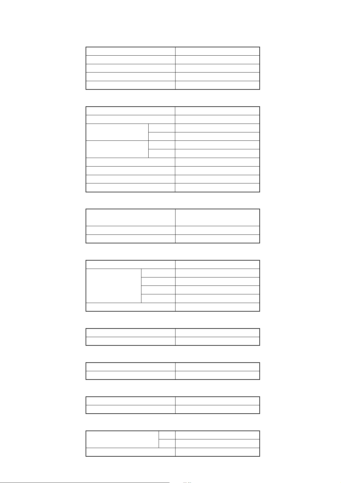
SPECIFICATIONS
TYPE
INDOOR UNIT
OUTDOOR UNIT
COOLING CAPACITY
HEATING CAPACITY
ELECTRICAL DATA
POWER SOURCE
FREQUENCY
RUNNING CURRENT
INPUT WATTS
E.E.R.
COP
MOISTURE REMOVAL
AIR CIRCULATION -High
COMPRESSOR
TYPE
COOLING
HEATING
COOLING
HEATING
COOLING
HEATING
COOL & HEAT INVERTER
MW18Y3F
MR18Y3F
5.28 kW
6.30 kW
208 - 230 V
60 Hz
7.7 A
8.6 A
1.73 kW
1.93 kW
3.05 kW/kW
3.28 kW/kW
2.8 L/hr
Cool 700 m3/hr Heat 700 m3/hr
Hermetic type, 4 pole, 3 phase,
DC inverter motor, Rotary
DISCRIMINATION
REFRIGERANT
FAN MOTOR
POWER SOURCE
INDOOR UNIT
OUTDOOR UNIT
DIMENSIONS
INDOOR UNIT
OUTDOOR UNIT
WEIGHT
INDOOR UNIT
OUTDOOR UNIT
NOISE LEVEL
INDOOR UNIT
OUTDOOR UNIT
R410A
HIGH-SPEED
MED-SPEED
LOW-SPEED
QUIET
H x W x D
H x W x D
GROSS / NET
GROSS / NET
DA / 30A / F-25F
1,150 g
208 - 230 V
Cool 1,480 r.p.m. Heat 1,480 r.p.m.
Cool 1,260 r.p.m. Heat 1,300 r.p.m.
Cool 1,040 r.p.m. Heat 1,110 r.p.m.
Cool 850 r.p.m. Heat 950 r.p.m.
Cool 860 r.p.m. Heat 820 r.p.m.
275 x 790 x 215 mm
578 x 790 x 300 mm
12 / 9 kg
44 / 40 kg
C 44 dB H 42 dB
C 50 dB H 50 dB
REFRIGERANT (R410A)
Pipe Length
FULL CHARGE AMOUNT
ADDITIONAL REFRIGERANT
15 m
20 m
2006.02.20 1
1,150 g
1,250 g
20 g / m
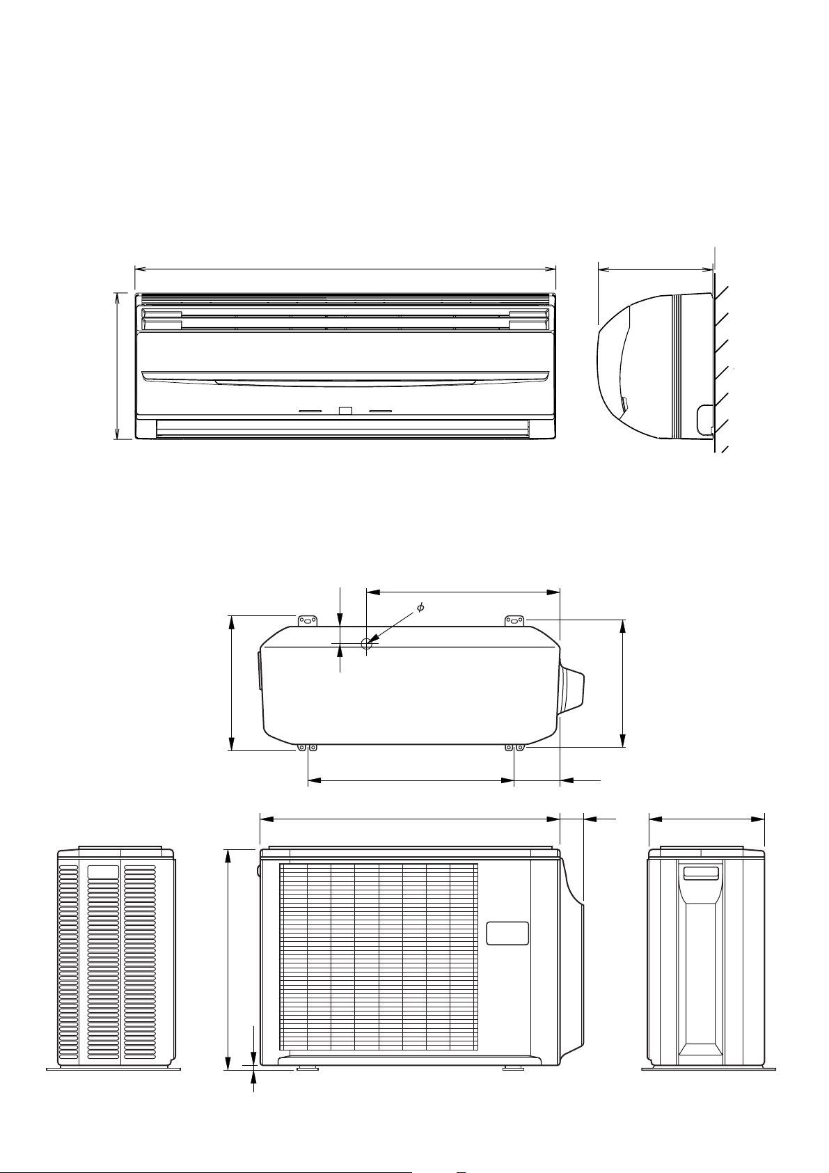
DIMENSIONS
Model : MW18Y3F / MR18Y3F
(unit : mm)
790
275
508
48
20
215
347
540
790
578
10
125
66
320
300
2006.02.20 2
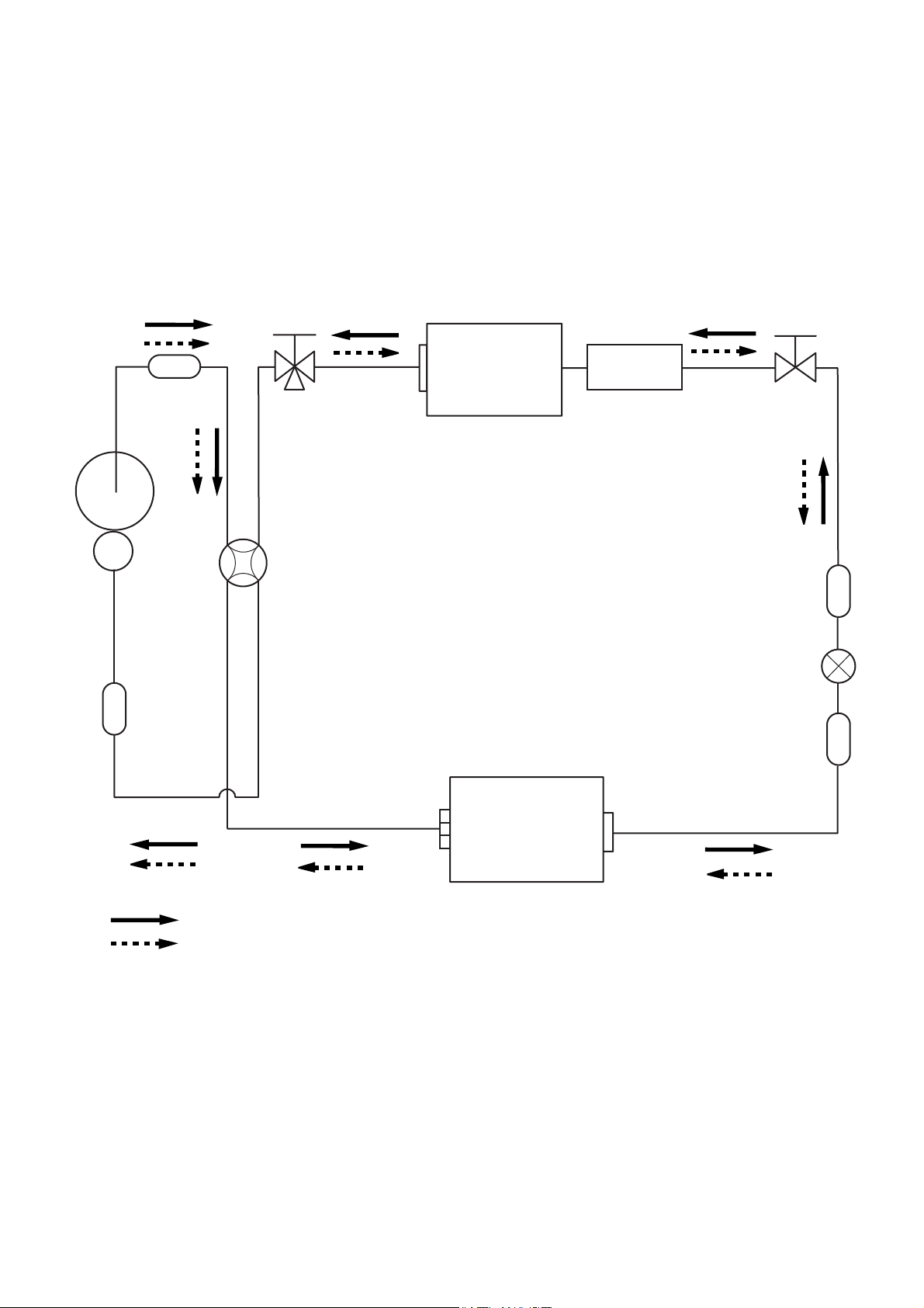
REFRIGERANT SYSTEM DIAGRAM
Model : MW18Y3F / MR18Y3F
Muffler
Compressor
3-Way
valve
4-Way valve
Heat exchanger
( INDOOR )
Sub-heat
exchanger
( INDOOR )
2-Way
valve
Strainer
Expansion valve
Sub-accumulator
Cooling
Heating
Refrigerant pipe diameter
Liquid : 1/4" (6.35 mm)
Gas : 1/2" (12.7 mm)
Heat exchanger
( OUTDOOR )
Strainer
2006.02.20 3
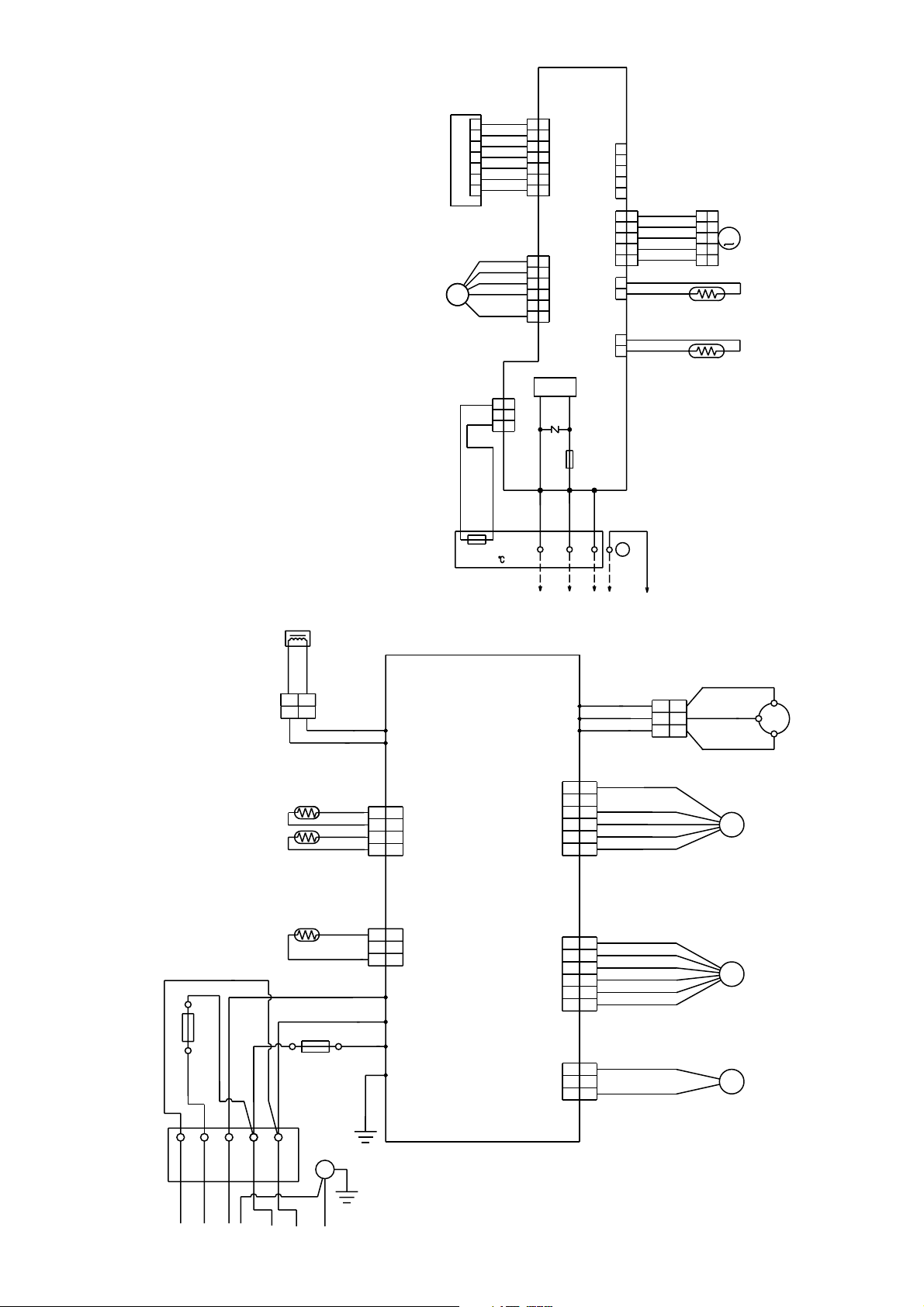
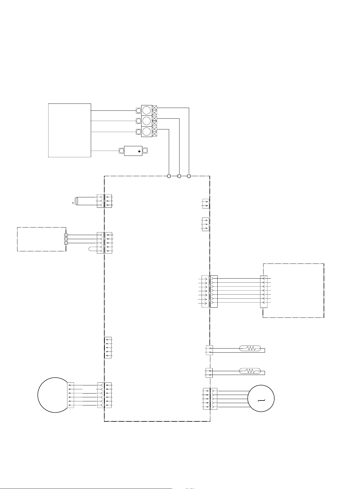
CIRCUIT DIAGRAM
Model :
MW18Y3F / MR18Y3F
INDOOR UNIT
OUTDOOR UNIT
CN201
1
2
3
4
5
6
7 7 7
INDICATOR PCB ASSY
FM
FAN MOTOR
GRAY
GRAY
THERMAL FUSE
TERMINAL
RED
1
WHITE
2
WHITE
3
WHITE
4
WHITE
5
WHITE
6
WHITE
BLUE
1
YELLOW
2
WHITE
3
BLACK
4
5
RED
6
POWER CIRCUIT
3
3
2
2
CN7
1
1
W1
102
1
2
3
4
5
6
1
2
3
4
5
6
WHITE
CN3
CN1
SW
W2
BLACK
CN10
CONTROLLER PCB ASSY
CN5 CN6 CN2
VARISTOR
FUSE
3.15A
W3
RED
321
1
2
3
4
5
1
2
3
4
5
1
2
1
2
G
RED
1
ORANGE
2
YELLOW
3
PINK
4
BLUE
5
BLACK
BLACK
PIPE TEMPERATURE
THERMISTOR
BLACK
BLACK
ROOM TEMPERATURE
THERMISTOR
GREEN /
YELLOW
1
1
2
2
3
M
4
5
STEP MOTOR
3
4
5
REACTOR
YELLOW
YELLOW
2
1
2
1
WHITE
PIPE TEMP. THERMISTOR
BLACK
BLACK
BROWN
BROWN
DISCHARGE PIPE TEMP. THERMISTOR
OUTDOOR TEMP. THERMISTOR
BLACK
BLACK
WHITE
RED
FUSE
WHITE
5A-250V
FUSE 20A-250V
BLACK
BLACK
BLACK
RED
BLACK
GREEN
W10
W11
1
1
2
2
CN71
3
3
4
4
CONTROLLER PCB ASSY
1
1
2
2
CN70
3
3
W4
W2
W1
W3
TO OUTDOOR UNIT
RED
W7
WHITE
W8
BLACK
W9
1
1
2
2
3
CN801
CN40
CN30
3
4
4
5
5
6
6
1
1
2
2
3
3
4
4
5
5
6
6
1
1
2
2
3
3
RED
BLACK
WHITE
YELLOW
BLUE
RED
BROWN
BLUE
ORANGE
YELLOW
WHITE
BLACK
BLACK
RED
WHITE
BLACK
F M
E V
4WV
R(R)
COMPRESSOR
C M
S(S)
C(T)
FAN MOTOR
EXPANSION VALVE
4-WAY VALVE
1
1
2
2
3
3
TERMINAL
TO INDOOR UNIT
1
3
2
(L)
POWER SUPPLY
(N)
G
5
4
2006.02.20 4
INDOOR PCB CIRCUIT DIAGRAM
Model : MW18Y3F
CONTROL UNIT
EZ-0051FHSE
TERMINAL BOARD
OUTDOOR UNIT
N
L
SERIAL
N
L
3
TERMINAL FUSE
REMOTE CONTROL UNIT
103
CN10-1 RED
CN10-2 WHITE
CN10-3 BLACK
EARTH
CN7
B3B-XASK
1
3
CN10
B5B-XASK
1
2
3
4
5
EARTH
TERMINAL
CONTROLLER PCB ASSY
K04CP-0504WSE-C1
CONTROLLER PCB ASSY
K04CP-0500HSE-C1
W3
RED
W2
BLACK
W1
WHITE
CN11
B2B-XH
1
2
CN12
B3B-XH
1
3
CN3
S7B-ZR-3.4
1
2
3
4
5
6
7
EX-OUT
EX-I N
ZHR-07
CN3-1 RED
CN3-2 WHITE
CN3-4 WHITE
CN3-5 WHITE
CN3-7 WHITE
CN3-8 WHITE
CN3-9 WHITE
EXTERNAL COMMUNICATION CONNECTOR
CN201
JB20-07HG
1
2
3
4
INDICATOR PCB ASSY
5
K02CB-0300HSE-D0
6
7
CN8
BS5P-SHF-1AA
FAN MOTOR
F. M.
TEST
CN4-6 RED
CN4-4 BLACK
CN4-3 WHITE
CN4-2 YELLOW
CN4-1 BLUE
CN3-1
CN3-2
CN3-3
CN3-4
CN3-5
1
2
3
4
5
CN1
S5 (6-5) B-XARK
6
5
4
3
2
1
2006.02.20 5
CN6
2P-SCN
CN5
2P-SAN
CN2
53325-0510
1
2
3
4
5
1
2
1
2
CN3-1 BLACK
CN3-2 BLACK
CN2-1 BLACK
CN2-2 BLACK
CN7-1 RED
CN7-2 ORANGE
CN7-3 YELLOW
CN7-4 PINK
CN7-5 BLUE
PIPE TEMPERATURE THERMISTOR
ROOM TEMPERATURE THERMISTOR
M
LOUVER

Model : MW18Y3F
GND
3 N L
W1
W3
W4
GREEN
WHITE
RED
VA1 270V
<TNR>
C3
0.22
<LE>
1
2
L1
8
18
3
R
/2W>
<1
7
14
6
10
IC10
5
5
4
4
3
3
2
2
5V
R27 390
1
1
<1/10W>
TERMINAL BOARD
W2
BLACK
3.15A - 250V
R2 2.2
<RGG-5W>
4
3
1K
R6 100K
<1/10W>
D7
DAN202K
HEAT EXCHANGER
THERMISTOR
F1
ROOM TEMPERATURE
THERMISTOR
D1
4
20V
C16
0.1
<F>
5V
R25 10K
<1/10W>
3
2
Q1
1
DTC124EUA
C34
0.01
<B>
160V
2
1
C5
3
100/
420V
IC7
78M15
123
I
O
G
Q2
DTC124EUA
3
1
R4 100K
<RS - 2W>
+
A
A
2
R26 390
<1/10W>
CN6
CN5
D2
1NH42
5
D
7
S
S
8
I C5
TNY266P
C18
0.1
<F>
1
2
C7 0.01
<ECQE>
EN / UV
BP
15V
+
C33
0.01
<B>
1
2
S
S
C17
330/
25V
5V
5V
R5 2.0M <1/2W>
4
3
2
1
R42 49.9K
<1/10W>
(1%)
R41 10K
<1/10W>
(1%)
20V
D3
D1FL20U
R7 18K
<1/10W>
+
C10
100/
35V
C6
0.1
<F>
MANUAL AUTO
SWITCH
(KSM0632B)
C11 0.01
<F>
5V
R22
10K
<1/10W>
R44 1K
<1/10W>
R43 1K
<1/10W>
ETS19AB1P8AG
6
5
4
1
2
4
3
A
I C11
PS2501L-1
<KD / KE>
R21 1K
<1/10W>
T1
C12
4700P
<E>
C46
0.1
<F>
C45
0.1
<F>
10
7
1
2
D4
C13
R24 10K
<1/10W>
12V
13.5V
D2FL20U
+
C
A
330 / 25V
C27
0.1
<F>
BZ1
PKM13EPY-4000
BZ
R38 10K
<1/10W>
13.5V
R10
C15
47K
0.01
<1/10W>
<B>
REF
I C8
TL431 I LP
R11
1K
<1/10W>
5V
8
VCC
4
D0
6
TEST
5
GND
IC4-6 LN2003
11 6
CONTROLLER PCB ASSEMBLY
K04CP-0500HSE-C1
CN7
B3B-XASK
1 1223
VA2 270V
<TNR>
IC3
CS
SK
D1
NC
R8
34K
<1/10W>
(1%)
R9
8.25K
<1/10W>
(1%)
1
2
3
7
C29 10K
C30 1000P <R>
C31 1000P <R>
12V
D6
D1F60
IC6
NJM7805
I
C19
+
330/
25V
R37
R36
R35
R34
330 <1/10W> x4
5V
3
O
G
C20
0.1
<F>
5V
R32R31
R33 R30
C22
330/
25V
REM
WIR
C23
+ +
10/
25V
IC1
UPD780058
61
P00
62
P01
63
P02
64
P03
65
P04
66
P05
73
XT1
72
XT2
76
P10
77
P11
78
P12
79
P13
80
P14
1
P15
2
P16
3
P17
11
P20
12
P21
13
P22
14
P23
15 43
P24
16
P25
17
P26
18
P27
44
P30
45
P31
46
P32
47
P33
48
P34
49
P35
50
P36
51
P37
19
P40
20
P41
21
P42
22
P43
23
P44
24
P45
25
P46
26
P47
10K <1/10W> x4
VDD0
VDD1
AVRF0
AVRF1
RST
P50
P51
P52
P53
P54
P55
P56
P57
P60
P61
P62
P63
P64
P65
P66
P67
P70
P71
P72
P120
P121
P122
P123
P124
P125
P126
P127
P130
P131
IC
X1
X2
AGND
GND0
GND1
C24
0.1
<F>
5V
74
68
75
7
60
27
28
29
30
31
32
34
35
36
37
38
39
40
41
42
8
9
10
52
53
54
55
56
57
58
59
5
6
71
70
69
4
67
33
CN8
BS5P-SHF
1
2
3
4
5
R16 R17
R15 R20
RXD
TXD
VPP
1
3
X1
2
5.00MHz
<CSTS>
TIMER SHORT CIRCUIT
CLOCK
DO
DI
TEST
R39 10K
<1/10W>
JP1
R18
R19
C26
0.1
<F>
5V
Q6
DTC124EUA
C50
1000P
<R>
IC2
BD4842
2
VDD NC
1
VOUT
3
GND
10K <1/10W> x6
JM7
JM6
JM5
JM4
JM3
JM2
IC4-5 LN2003
3
2
1
R53 1K
<1/10W>
5V
4
C25
0.1
5
NC
<F>
AUTO RESTART
HOME AUTOMATION
ROOM TEMPERATURE
CORRECTION 1
ROOM TEMPERATURE
CORRECTION 2
CUSTOM CODE 1
CUSTOM CODE 2
12V
8
C62
0.1
IC9
<F>
4
WIR
5 12
5V 15V
R50 330
<1/10W>
5V
R54 10K
<1/10W>
IC12
PS2501L-1
<KD / KE>
1
2
4
3
IC13
PS2501L-1
<KD / KE>
R80
12V
9
IC4
8
5V
R65 10K
<1/10W>
R66 390
<1/4W>
(1%)
IC4-4 LN2003
IC4-3 LN2003
IC4-2 LN2003
IC4-1 LN2003
4
3
15V
1
2
R28 10K
<1/10W>
RXD
TXD
VPP
5V
R81 R82 R83
REM
IC9-2
BA10393F
7
1
IC9-1
BA10393F
R51 1K
<1/4W>
(1%)
R52 820
<1/4W>
(1%)
R55 4.7K
<1/10W>
5V
R23
6
5
+
2
3
+
R56 6.8K
<1/4W>
R29 10K
<1/10W>
5V
10K <1/10W> x4
R61 10K
<1/10W>
C60
1000P
<R>
IC4-7 LN2003
12V
R63 15.4K
<1/10W>
(1%)
R64 28K
<1/10W>
(1%)
R68 1K
<1/10W>
13
4
14
3
15
2
1
16
C53
100 / 16V
+
A
A
R84
R85
R86
R87
R89
5V
R62 10K
<1/10W>
330 <1/10W> x6
R60 47
<1/10W>
5 12
12V
12V
5 4 3 2 1
D50
RD27M
<B>
JP2
12V
D61
DAN217U
CN2
53325-0510
15V
JP3JP4
R67 10K
<1/10W>
160V
5V
+
C80
100 / 16V
C81
0.01
<B>
D60
D1F60
5V
JP5
LOUVER
CN1
S5 (6-5) B-XARK
1 2 3 4 5 6
A
CN3
S7B-ZR-3.4
INDICATOR PCB
7 6 5 4 3 2 1
12V
CN10
B5B-XASK
5 4 3 2 1
DC FAN MOTOR
RED
WHITE
BLACK
JP SETTING
REMOTE
CONTROL
UNIT
C35 0.1 <F>
C36 0.1 <F>
C37 0.01 <B>
C38 0.1 <F>
2006.02.20 6

Model : MW18Y3F
INDICATOR PCB ASSY
K03DV-0400WSE-D0
5V
D206 SLR-325
D204 SLR-325
D203 SLR-325
D201 SLR-325
I C201
GP1UM261R
5V
CN201
1
1
1
2
2
2
C201
0.1
1
2
<F>
1
2
3
4
5
6
7
8
9
5V
R201
47
VCC
OUT
GND
2
1
3
<1/4W>
C202
+
47/
10V
72006.02.20

OUTDOOR PCB CIRCUIT DIAGRAM
Model : MR18Y3F
N
TO
INDOOR
UNIT
AC208-230V
60Hz
SERIAL
1
L
2
3
4
5
UL1015 AWG20
W100 WHITE
UL1015 AWG20
W103 BLACK
UL1015 AWG20
W102 BLACK
UL1015 AWG14
W101 BLACK
F202
5A-250V
F201
20A-250V
UL1015 AWG14
BLACK
UL1015 AWG14
WHITE
UL1015 AWG20
RED
UL1015 AWG16
GREEN
W1
( A-1 )
W2
( B-1 )
W4
( D-1 )
W3
( C-1 )
INVERTER ASSEMBLY
EZ-005SHUE
EMI FILTER
RED
WHITE
BLACK
4-WAY VALVE
A
C. M.
COMPRESSOR
REACTOR
B
B
B
B
B
W7
W8
W9
U
V
W
UL3271 AWG16
UL3271 AWG16
WHITE
UL3271 AWG16
BLACK
RED
B
1
CN30
BLACK
2
3
B
UL3271 AWG14
WHITE
W10 W11
UL3271 AWG14
RED
BB
B2P3-VH-B-C
BLACK
BLACK
CONTROLLER PCB ASSY
K05CM-0507HUE-C1
TERMINAL
DISCHARGE TEMPERATURE THERMISTOR
PIPE TEMPERATURE THERMISTOR
OUTDOOR TEMPERATURE THERMISTOR
BLACK
BLACK
BROWN
BROWN
BLACK
BLACK
1
2
CN71
B04B-PASK-1
3
WHITE
4
1
CN70
2
B03B-PASK-1
WHITE
3
CN801
B5P6-VH-B-L
WHITE
CN40
B6B-XARK-1-A
RED
1
2
3
4
5
6
1
2
3
4
5
6
RED
BLACK
WHITE
YELLOW
BROWN
RED
BROWN
BLUE
ORANGE
YELLOW
WHITE
EXPANTION VALVE
M
F. M.
DC FAN MOTOR
2006.02.20 8

Model : MR18Y3F
AC208 - 230V
60Hz
W1
L
BLACK
VA1 470V
<TNR>
VA2 470V
<TNR>
W2
N
WHITE
RA-302M
GREEN
RED
CN71
CN70
W3
W4
DCV-F
1
2=3
1
2
3
4
5
6
1
2
3
4
5
6
1
2
3
4
1
2
3
EARTH
SERIAL
CN30
B2P3-VH-B-C
4-WAY VALVE
CN801
B5P6-VH-B-L
WHITE
FAN MOTOR
CN40
B6B-XARK-1-A
RED
EXPANSION VALVE
PIPE TEMP.
THERMISTOR
DISCHARGE TEMP.
THERMISTOR
OUTDOOR TEMP.
THERMISTOR
18
SA1
C802
0.1
<F>
5V
POW_GND
L800
BL02Rn1
L40
5mmJP
L70
BL02Rn1
R72
6.65K
1%
C75
0.1
<F>
R73
38.3K 1%
15V
12V
R71
4.75K
1%
14
78
CR30
RE1201
C800
100/
25V
TD62064
2
7
9
16
4
5
12
13
+
POW_GND
O1
O2
O3
O4
GND1
GND2
GND3
GND4
R75
10K
R76
10K
R77
10K
1
C1
0.1/
275V
4 3
RCH4716-070PF07
HY I C1
HU2001 or GK30434
10
R801 1.0K
<1/4W>
R802
560
<1/4W>
12V
I C40
3
I 1
6
I 2
11
I 3
14
I 4
1
COM1
8
COM2
10
NC1
15
NC2
C71
0.1
<F>
C72
0.1
<F>
C73
0.1
<F>
2
L1
6
JM32
JM31
15V
1
3
Q801
DTA143EUA
5V
R803
10K
<1/10W>
R40
R41
R42
R43
1.5K <1/10W> x 4
C40
0.1
<F>
TE / 5P
TD / 4P
TA / 6P
C4
0.01/250V
C5
0.01/250V
5V
2
5V
2
3
5
5
1
3
K30
FTR-F3
or
G5NB-1A
3
1
1
D600
DAN217U
R804
1.0K
EPV3 / 44P
EPV4 / 43P
EPV2 / 42P
EPV1 / 45P
SO / I C80-2
V4-AC / I C80-3
V4-DC / I C80-4
PR / I C80-5
ACFAN / I C80-6
C6
3.3/275V
4 3
2 1
4
3
SO / I C80-2
V4-AC / I C80-3
2
12V
4
Q800
DTC143EUA
FANPWM / 2P
2
FAN IN / 17P
C801
0.01
<F>
12V
D80
SLR-332
<RED>
R80
2.2K
12V
JM30
12
I C80
uLN2003
16
1C
15
2C
14
3C
4C
13
12
5C
6C
11
7C
10
9
COM
R1
ZPR0RCH400
-0
12V
231
K1
G4A-1A
or
DW12D1
PFC / 58P
5V
R21
10K
<1/10W>
R22 1.0K <1/10W>
R23
27K
<1/10W>
R147
R148
C123
2200P
<B>
R149
4.7K
1%
1
1B
2
2B
3
3B
V4-DC / 29P
4
4B
5B
5
ACFAN / 28P
6
6B
7
7B
8
E
REACTOR
W10
W5
W6
4
PR / I C80-5
R157
4.7K
R20 1.0K
<1/10W>
0.047
R150
195K <RN-1/2W>
1% x 4
R151
D110
DAN217U
-12V
R144
22K 1%
R145
22K 1%
C124
2200P
<B>
R152
4.7K
1%
LED / 30P
SO / 32P
V4-AC / 27P
PR / 31P
LL25XB60 x 2
W11
2
3
2
3
DAN217U
C137
0.1
<F>
+
C138
2.2/50V
C21
<B>
PFCEN / 14P
15V
2 1
3
2 1
3
D111 DAN217U
9
10
I C104-3
BA2902F
R146
39K
1%
FAN IN / 17P
FANPWM / 2P
PFCSW / 35P
CT / 3P
TEST / 59P
PFC / 58P
T TXD / 60P
T AUX3 / 21P
CP-POS / 47P
V4-AC / 27P
ACFAN / 28P
V4-DC / 29P
LED / 30P
PR / 31P
SO / 32P
I PM-TRIP / 33P
E2CS / 41P
EPV2 / 42P
EPV4 / 43P
EPV3 / 44P
I PM-CR / 9P
DCV / 8P
ACV / 7P
TE / 5P
TA / 6P
TD / 4P
D105
-12V
R143
39K
1%
-
+
D100
+
-
D101
+
-
R155
100K
1%
R156
100K
1%
ZXL / 37P
S I / 48P
C20
0.1
<F>
C130
0.1
<F>
R159
4.7K
C129
1000P
<B>
8
C500
1
4
1
4
15V
2
1
3
R153
120K 1%
6
5
I C3-2
BA4560
R154
120K
Q103
DTC143EUA
2
15V
R160
68K
1%
R161
1.5K
1%
R137 10K 1%
R140
10K
1%
R139
SERVICE
JM501
0.1
<F>
+
R132
2.2K
10K
1%
1 3
5V
2
R400
0.20 <1W> 1% x 8
R401
R402
R403
R404
R405
R406
R407
R127
R128
10K 1% x 2
7
R142
1.2K
1%
R131
10
5V
1%
2
3
1
R162
68K
1%
3
+
2
-
I C105-1
BA2903F
R138 10K 1%
D109
RB751V
6
-
5
+
I C104-2
BA2902F
R504 10K
<1/10W>
I C500
MB90460
P63
17
VCC
P62
16
AVCC
P46
2
35
P12
P50
3
59
P37
58
P36
P40
60
21
MD2
34
AVR
P11
47
P26
27
P02
28
P03
29
P04
30
P05
31
P06
32
P07
33
P10
57
C
41
P20
42
P21
MD0
43
P22
MD1
44
P23
10
P57
9
P56
8
P55
7
P54
P52
5
RSTX
P53
6
4
AGND
P51
22
X0
GND
23
GND
X1
X500
8.00MHz
<CSTS>
R130
220
1%
3
Q102
1
5V
R163
10K 1%
1
6
5
BA2903F
R136 10K 1%
7
D108
RB751V
5V
56
11
25
P00
26
P01
40
P17
36
P13
37
P14
38
P15
39
P16
12
P24
45
P25
46
50
P30
51
P31
52
P32
53
P33
54
P34
55
P35
14
P60
15
P61
18
20
64
P44
63
P43
62
P42
61
P41
P45
1
19
48
P27
13
24
49
R126
100K
I C103-1
BA4560
2
3
R129
100K 1%
I C3-1
BA4560
2
3
DTC143EUA
ZXH / 36P
-
+
I C5-2
R500
10K
C502
0.1
<F>
1%
-
+
-
+
C117
1.0
<B>
7
R135
10K
1%
R141
10K
10/25V
CONTROLLER PCB ASSY
K05CM-0507HUE-C1
GT30J122
1%
C501
C119
<F>
1
1
R502
1.0K
+
15V
0.1
-12V
6
5
R166 3.9K
DAN217U
D107
RB751V
R134
10K
1%
I C104-1
BA2904F
2
-
3
+
I C104-4
BA2902F
13
12
C503
0.1
<F>
C120
0.1
<F>
-
7
+
R122
R123
R158 3.9K
1 1
D115
10K 1%
R133
10K
1%
1
-
+
R503
10K
PFCEN / 14P
R561
C561
0.01
<F>
C139
I C103-2
BA4560
4.7K
1% x 2
3 3
2 2
R118
D119
10K
1%
14
SERVICE
JM500
T AUX / 25P
PFC-R RIP / 46P
T MODE / 18P
TRXD / 61P
/ T RES / 19P
1.0K
5V-2
+
2.2/
50V
D114
DAN217U
R116
15K
1%
C111
4700P
<B>
R164
22K
C125
0.1
<F>
15V
C115
0.1
<F>
C116
0.1
<F>
-12V
E2SK / 40P
ZXH / 36P
ZXL / 37P
E2D I / 39P
EPV1 / 45P
U / 50P
X / 51P
V / 52P
Y / 53P
W / 54P
Z / 55P
MD1 / 64P
MD2 / 63P
TCK / 62P
MD0 / 1P
S I / 48P
R560
100K
5V
C140
0.1
<F>
R121
100K
1%
I C102-2
BA2901F
7
+
6
-
C113
2700P
<B>
5V-2
R117
22K
1%
COMP
5V
Q100
L130
ELC0607RA
R120 4.7K 1%
1
C142
0.1
<F>
R115
22K 1%
5
+
4
I C102-1
BA2901F
C135
1000P <B>
C126
+
2.2/
50V
R168
22K
T AUX / 25P
T TXD / 60P
T RXD / 61P
T MODE / 18P
T AUX3 / 21P
T CK / 62P
/ T RES / 19P
2
VDD
1
OUTNCGND
I C560
S80842
D102
1NH42
R103
<1/2W>
R102
R125 4.7K
11
+
10
-
I C102-4
BA2901F
R171
4.7K
2
R165
22K
C127
50V
R170
68K
3
4
100
1
47K
13
5V-2
2.2/
5V
R112
10K
1%
C131
0.1
<F>
2
3
1
5
7
3
R124
4.7K
+
R581
10K
E2CS / 41P
E2SK / 40P
E2D I / 39P
MD0 / 1P
MD1 / 64P
MD2 / 63P
TEST / 59P
C103
0.1
<HCP>
<1/4W>
<1/4W>
R108 47
R109 22
2
VCC
GAT I N
6
SO
S I
D I
4
GND
NC
I C100
TA8316
I C101
TC 74HC00AF
1
1
14
2
2
13
3
3
12
4
4
11
5
5
10
6
6
7
7
R101
4.7K
C141
1000P
<B>
I C102-3
BA2901F
C110
0.1
<F>
15V
C112
0.1
<F>
5V
C128
0.1
<F>
R169
22K
C132
+
2.2/
50V
R582
10K
R585
1.0K
0.01 <F>
R93
+
15V
C105
0.1
<F>
14
13
12
11
10
9
9
8
8
0.1 <F>
R113 4.7K
+
4
-
C136
0.01
<F>
1
C133
2.2/
50V
+
R583
1.0K
C572
10K x 4
R91R92
C100-C102
660/450V x 3
+ +
L100 BL02Rn1
15V-2
C104
+
10/
25V
5V
C106
5V-2
1%
9
8
R1
15K
1%
3
D112
DAN217U
2
5V
C134
0.1
<F>
C580
R584
22K
I C570
BR93LC46
1
CS
2
SK
D I
3
NC
6
5V
R90
PFCAW / 35P
PFCEN / 14P
PFC-TRIP / 46P
R167
10K
DAN217U
R111
10K
3
1
0.1
<F>
VCC
DO
NC
GND
R570
10K
F100
15A-250V
F4
BET 3.15A-250V
PFC5000
-0702F
R104
220K
<2W>
PFC5000-0702F
DC V
R107
3.83K
1%
POW_GND
5V
D106
2 1
R110
3
6.8K
C108
+
2.2/
50V
DCV / 8P
C109
+
2.2/50V
CT / 3P
ACV / 7P
D113
DAN217U
2
5V
1
2
3
4
5
6
7
8
9
10
5V
8
4
7
C570
5
0.1
<F>
AOUS09LAC
JM101
JM102
JM103
JM100
AOUS12LAC
JM101
JM102
JM103
JM100
FH2
F50
3A
FH1
DCV-F
POW_GND
R105 195K
<RN-1/2W>
1%
R106 195K
<RN-1/2W>
1%
C107
0.1
<F>
COMP
CN580
B10B-PASK-1
WHITE
T AUX
T TXD
T RXD
T MODE
T AUX3
T CK
/ T RES
/ T ICS
UDZS8.2B
L50
BLm21AG610
L51
TEST
TEST
DC V
D200
R203 330K
390 <1/10W> x 6
U / 50P
V / 52P
W / 54P
X / 51P
Y / 53P
Z / 55P
I PM-TRIP / 33P
C219
1000P
<B>
I PM-CR / 9P
CP-POS / 47P
15V
D50
1SS355
D51
x 2
D52
1SS355
R51
47
C50
47/
35V
POW_GND
U1JU44 x 3
+
C204 47 / 35V
C205 0.1 <F>
R218 4.7K
<1/10W>
470K
<1/8W>
510K
<1/8W>
+
D201
R202 330K
R204
R205
R206
R207
R208
R209
R219
1.0K
R220
1.0K
5V
R339
10K
3
1
Q300
DTC114EUA
DC V - F
R52
1%
R53
x 3
R54
R55
C51
1.0
<B>
C203 0.1 <F>
5V
R334
R56
150K
<2W>
R200 39
<1/2W>
+
C202 47 / 35V
2
C320
0.15
<ECQB>
5V
10K
1%
2 1
I C302-1
BA2903F
UF4005
TOP243P
1
MSS
2
S
3
C
4
5V
3
C300
100P
<CH>
2200P
I C50
D202
R201 330K
C201 0.1 <F>
C206-C208
D301
1
DAN217U
R327
22K
R337
100K 1%
-
+
C339
C52
<E>
R57
0R0
D53
8
S
7
5
D
+
C200 47 / 35V
D302 RB751V
C311
1000P
<B>
5V
2
3
0.01
<F>
<1/16W>
R83 27K
<1/10W>
RPZ-1F
1
2
3
4
5
C210 0.1 <F>
C209 0.1 <F>
I PM-G
2200P <B> x 6
R328
1.0K
5V
R336
R335
10K
10K
1%
1%
R338
1%
5V
R81
1.0K
7
I C302-2
BA2903F
T60
10
9
8
7
6
15V
C212 0.1 <F>
C211 0.1 <F>
C221 0.1 <F>
C215-C217
R329 47K 1%
I C300-1
BA4560
2
-
1
3
+
R331
47K 1%
5
+
7
6
-
I C300-2
BA4560
R333
10K
1%
C330
1000P
<B>
C85
+
10/
25V
6
-
5
C84
0.1 <F>
D60
D1FL20U
D61
D1FL20U
D62
D1FL20U
C66
100/
25V
D64
1SS355
L300
ELC0607RA
C222 1.0 <B>
D203 MTZJ T-77 24B
C213
0.022
<F>
I PM-G
R330
4.7K
1%
R332
4.7K
1%
15V
C306
0.1
<F>
C305
0.1
<F>
-12V
D304
15V
DAN217U
C86
470P
<B>
C87
330P <B>
C64
+
330/
25V
+
+
C220 47 / 35V
I PM-G
2 1 2 1
3 3
I C60
BA7805
D63
1SS355
1
G
2
C69
+
100/
25V
-12V
I C200
FSBS20CH60
1
VCC
2
COM
I N
3
4
I N
5
I N
6
VFO
7
CFOD
8
CSC
9
I N
10
VCC
11
VB
12
VS
I N
13
14
VCC
15
VB
16
VS
I N
17
18
VCC
19
VB
20
VS
R210 1.0K
C214
2200P
<B>
W V U
R305
R306
195K <RN-1/2W> 1% x 6
D303
DAN217U
C65
+
470/
25V
3IO
R303
R304
NU
NV
NW
U
V
W
P
R309
5.76K
1%
R310
143
1%
C67
0.1
<F>
21
22
23
24
25
26
27
R301R302
U V W
W7
W8 W9
U V W
<1W>
I PM-G
R307 195K
<RN-1/2W>
R308 195K
<RN-1/2W>
R311
8.66K
1%
R61
1.0K
R211
R212
R213
R214
R215
R216
R217
1%
x 7
15V
12V
5V
POW_GND
C68
+
100/
25V
DC V
C218
0.1
<HCP>
2006.02.20 9

ERROR CONTENTS
Model : MW18Y3F / MR18Y3F
Self-diagnosis function table (Flashing LED Display)
* Detailed Trouble Display (secondary level) can be indicated by pressing Test Operation button.
Trouble Display (primary)
Error Operation Timer Error Operation Timer
Serial signal
error
Indoor unit
thermistor
error
Normal 1 sec
blinking
0.5sec
2 times
0.1sec
blinking
Detailed Trouble Display (by Test Button)
Serial reverse signal error
at operation start up
Signal reverse signal error
during operation
Serial forward signal error
at operation start up
Serial forward signal error
during operation
Indoor temperature
thermistor open
Pipe thermistor
open or short
0.1sec
blinking
0.1sec
blinking
0.1sec
blinking
0.1sec
blinking
0.1sec
blinking
0.1sec
blinking
0.5sec
2 times
0.5sec
2 times
0.5 sec
4 times
0.5sec
5 times
0.5sec
2 times
0.5sec
3 times
Detailed Error Item
When a signal is not read continuously for 10 secs
from power relay ON immediately after operation starts
>>Cooling 0 code transmission, automatic reset
When a signal is not read for 20 secs thereafter
>>Trouble display continues and power relay OFF
>>Permanent stop
When a signal is not read continuously for 10 secs
from power relay ON immediately after operation starts
>>Cooling 0 code transmission, automatic reset
When a signal is not read for 20 secs thereafter
>>Trouble display continues and power relay OFF
>>Permanent stop
Normal Serial Forward Signal can not be
received more than 10 secs
>>Releases when it becomes normal
Normal Serial Forward Signal can not be
received more than 10 secs ( after receiving
effective forward transfer signal)
>>Releases when it becomes normal
Thermistor detection value is open when
AC plug is inserted
IndoorIndoorIndoorIndoorIndoor OutdoorOutdoorOutdoor
>>Releases when value becomes normal
Thermistor detection value is open or short
when AC plug is inserted
Outdoor unit
thermistor
error
Indoor unit
control error
0.5sec
3 times
0.5sec
4 times
0.1sec
blinking
0.1sec
blinking
Discharge thermistor
open or short
Heat exchanger
thermistor open
Outdoor temperature
thermistor open or short
Forced automatic SW
welded
Main relay welded
Power interruption error
0.1sec
blinking
0.1sec
blinking
0.1sec
blinking
0.1sec
blinking
0.1sec
blinking
0.1sec
blinking
0.5sec
2 times
0.5sec
3 times
0.5sec
4 times
0.5sec
2 times
0.5sec
3 times
0.5sec
4 times
>>Releases when value becomes normal
Thermistor detection value is open or short
>>Outdoor unit stops
Releases when it becomes normal
Thermistor detection value is open
>>Outdoor unit stops
Releases when it becomes normal
Thermistor detection value is open or short
>>Outdoor unit stops
Releases when it becomes normal
Forced Auto SW is ON for more than
10 secs continuously
>>Error is indicated while it is ON
Normal Operation other than error indication
Serial Reverse Signal is received 1 min.
after Main relay becomes OFF
>>Error is indicated while serial reverse
signal is input on normal operation
Normal operation except error indication
50/60Hz is not detected after 4 secs of
power ON.
2006.02.20 10
>>Error is indicated and unit is stopped

Trouble Display (primary)
Error Operation Timer Error Operation Timer
Outdoor unit
control error
Indoor fan
motor error
Refrigerant
cycle error
Optional
function
error
0.5sec
5 times
0.5sec
6 times
0.5sec
7 times
0.5sec
8 times
1 sec
blinking
0.1sec
blinking
0.1sec
blinking
0.1sec
blinking
Detailed Trouble Display (by Test Button)
Current trip Current trip error is 2nd time within
CT abnormal Current detection value is 0A for more
Compressor rotation
error
Outdoor unit fan drive
system abnormal
Abnormal lock Detected rotation is 0 r.p.m. at start up or
Abnormal rotation Detected rotation is 1/3 of target r.p.m. at
Discharge temperature
abnormal
Cooling high pressure
abnormal rise
Active filter voltage
abnormal (3rd time)
Active filter foltage
abnormal (1st time)
0.1sec
blinking
0.1sec
blinking
0.1sec
blinking
0.1sec
blinking
0.1sec
blinking
0.1sec
blinking
0.1sec
blinking
0.1sec
blinking
0.1sec
blinking
0.1sec
blinking
0.5sec
2 times
0.5sec
3 times
0.5 sec
5 times
0.5sec
6 times
0.5sec
2 times
0.5sec
3 times
0.5sec
2 times
0.5sec
3 times
0.5sec
2 times
0.5sec
3 times
Detailed Error Item
start up
>>Permanent stop
than 1 sec when compressor is
operated at more than 56rps
>>Automatic release after 3 min. ST
Compressor location detection error (incl.
failed start up) for 3 times
>>Permanent stop
When outdoor fan abnormal fan motor
duty abnormal operated 5 times
>>Permanent stop
at 56 secs after Fan mode is selected
Indoor
>>Permanent stop
start up or at 56 secs after Fan mode is
selected
IndoorOutdoorOutdoor Outdoor Outdoor Outdoor Outdoor Outdoor
>>Permanent stop
Discharge Temperature protection
(Discharge temperature is 110degC)
operated 2 times
>>Permanent stop
High pressure rise protection (Outdoor
heat exchanger temperature is 65degC)
operated
>>Comp. OFF (releases after 3min.ST)
Outdoor
Error is indicated while 3 min.ST
Active Filter voltage error operated 3 times
>>Permanent stop
Active Filter Module error or open
detection protection operated
2006.02.20 11
>>Automatic release after 3 min. ST

DISASSEMBLY ILLUSTRATION
Model : MW18Y3F
5
51
6
5
4
2
1
1
2006.02.20 12
2
7

Model : MW18Y3F
236
26
48
52
20
24
29
27
39
40
37
28
46
43
21
32
30
61-2
61-1
36
32
38
42
33
2006.02.20 13

Model : MR18Y3F
14
37
13
11
19
32
10
29
25
24
37
8
5
22
12
21
15
26
35
1
2
18
34
20
3
6
36
39
16
2006.02.20 14
7
4

PARTS LIST
INDOOR UNIT
Ref.
No.
20 Gear-A 9309994003
21 Casing Assy 9311354079
24 Crossflow Fan Assy 9307836015
26 Clamp (Motor) 9310102008
27 Shaft Holder-C Assy 9306628017
28 Drain Hose Assy 9314147012
29 Drain Cap Assy 9314493010
30 Wire Clamper 9311946014
32 Cover (Switch) 9313943011
33 Evaporator Total Assy 9313099015
Description
1 Air Filter 9309997011
2 Filter (Electric + ION) 9312152018
4
Holder (Filter) 9306602017
5
Clamper (Grille) 9306755010
6 Front Panel 9309999053
7 Intake Grille Assy 9313566043
Part No.
MW18Y3F
Ord.
Q'ty
36 Joint Pipe Assy 9313792015
37 Insulation (Pipe)-E 9304607007
38 Holder (Evaporator)-L Assy 9313174019
39 Holder (Evaporator)-R 9309983014
40 Water Seal 9312912018
42 Air Seal 9310611005
43 Terminal 9701955114
46 Step Motor 9900139025
48 Fan Motor Assy 9602109012
51 Remote Control Unit 9315260017
52 Bracket Panel 9310001004
61-1 Flow Control Panel-U 9309991033
61-2 Flow Control Panel-Z 9309992030
236 Controller PCB Assy 9707193015
(K04CP-0500HSE-C1)
--- Pipe Temperature Thermistor 9702039042
---
--- Indicator PCB Assy 9705039032
---
Room Temperature Thermistor
Evaporator B Assy 9311275022
9700801108
2006.02.20
15
When you order parts, please make a photocopy of this page
and fill the number of the parts in the "Order" column.

OUTDOOR UNIT
Ref.
No.
1 Top Panel Assy 9309230057
2 Top Panel Seal 9309228016
3 Cabinet Sub Assy 9314809040
4 Blow Down Grille 9308884015
5 Cabinet Right Assy 9309236011
6 Fan Ring 9308885012
7 Grip 9308880017
8 Switch Cover Assy 9309237049
10 4-Way Valve 9970056017
11 Expansion Valve Assy 9311641018
12 Strainer 9311440017
13 Condenser Assy 9311382027
14 Thermistor Spring-A 313728262708
15 Thermistor Spring-A 9300089012
16 Propeller Fan 9309909014
18 Motor Bracket 9308872012
Description
Part No.
MR18Y3F
Ord.
Q'ty
19 Separator 9312971015
20 Base Assy 9308869081
21 3-Way Valve Assy 9315159014
22 2-Way Valve Assy 9313064013
24 Cord Clamp 9307271014
25 Terminal 9703874024
26 Inverter PCB Assy 9707039085
29 Fuse 0600382018
32 Expansion Valve Coil 9900057039
34 Fan Motor 9602133017
35 Compressor Assy 9313764012
36 Emblem Rear 9312661015
37 Heat Exchanger Thermistor 9900148027
39 Solenoid Coil 9970033025
--- IPM 9705720015
---
---
Outdoor Temp. Thermistor 9900210045
Thermistor
Thermistor Assy--- 9900148027
9900041014
2006.02.20
16
When you order parts, please make a photocopy of this page
and fill the number of the parts in the "Order" column.
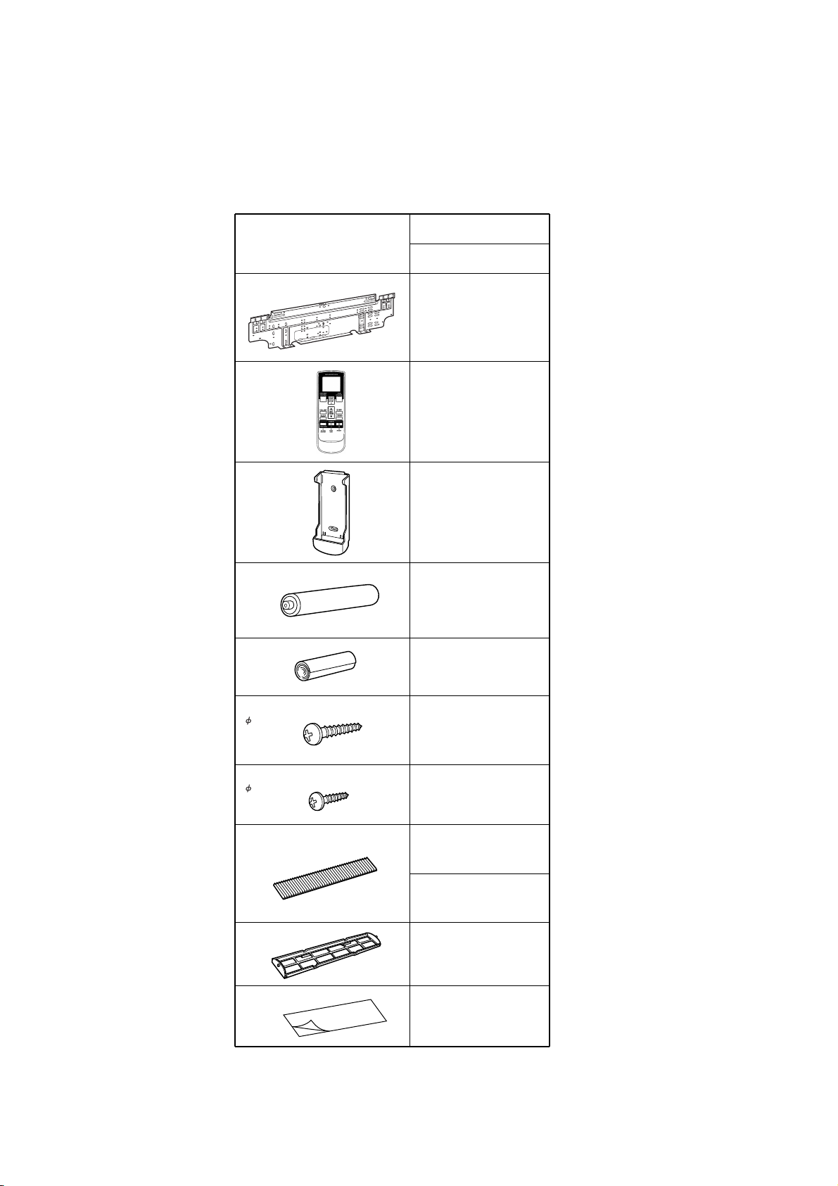
STANDARD
ACCESSORIES
Name and Shape
Wall hook bracket
Remote control
unit
Remote control
unit holder
Part No.
MW18Y3F
9312752010
9314990038
9305642014
Battery (penlight)
Cloth tape
Tapping screw (big)
( 4 x 25)
Tapping screw (small)
( 3 x 12)
Air cleaning filter
Air cleaning filter
frame
0600185534
9310519004
0700076046
0700019036
9312153015
9311925033
9306602017
Seal A
2006.02.20 17
9304536000

0511G2952
 Loading...