


Service and Parts Manual
2 0 11
SPLIT TYPE ROOM AIR CONDITIONER WALL MOUNTED TYPE
MODELS
INDOOR UNIT |
MW09C1H |
MW12C1H |
|
|
|
OUTDOOR UNIT |
MR09C1H |
MR12C1H |
|
|
|
Table of Contents
Model and product code .................................................................................................. |
3 |
|
Summary and features |
......................................................................................................... |
4 |
|
||
1.SafetyPrecautions |
............................................................................................................... |
5-7 |
|
||
2.Specifications ........................................................................................................................... |
8 |
|
2.1Unit Specifications........................................................................................................... |
|
8-11 |
2.2 Operation Date............................................................................................................... |
12 |
|
2.3Expanded capacity data tables for both cooling and heating ...................................... |
13 |
|
2.4Operation Characteristic Curve...................................................................................... |
14 |
|
2.5 Noise criteria curve tables for both models.................................................................... |
15 |
|
3.ConstructionViews.............................................................................................................. |
16 |
|
3.1IndoorUnit ....................................................................................................................... |
16 |
|
3.2OutdoorUnit .................................................................................................................... |
16 |
|
4.RefrigerantSystemDiagram |
....................................................................................... |
17 |
|
||
5.SchematicDiagram |
.............................................................................................................. |
18-21 |
|
||
5.1ElectricalDate |
|
18 |
|
|
|
5.2ElectricalWiring ........................................................................................................... |
|
18-19 |
5.3PrintedCircuitBoard ..................................................................................................... |
|
20-21 |
6.FunctionandControl ....................................................................................................... |
22-35 |
|
7. Installation Manual............................................................................................................ |
36-43 |
|
8.Troubleshooting ................................................................................................................... |
|
44-72 |
9.1Precautions before ....................................................Performing Inspection or Repair |
44 |
|
9.2Confirmation ................................................................................................................. |
44 |
|
9.3Judgement by Flashing LED of Indoor/Outdoor UnIT ........................................................... |
44-51 |
|
9.4 How to Check simply the main part .................................................................................... |
52-62 |
|
9. Removal Procedure |
....................................................................................................... |
73-78 |
|
||
10. Exploded Views and Parts List |
............................................................................. |
79-85 |
|
||
2

Model and product code
Model and product code
Voltage range |
Complete unit model |
Indoor unit model |
Outdoor unit model |
|
|
|
|
|
|
115V ~ 60HzM |
M09CIH |
MW09CIH |
MR09CIH |
|
|
|
|
|
|
115V ~ 60HzM |
M12CH |
MW12CIH |
MR12CIH |
|
|
|
|
|
|
3
Summary and features
Summary and features
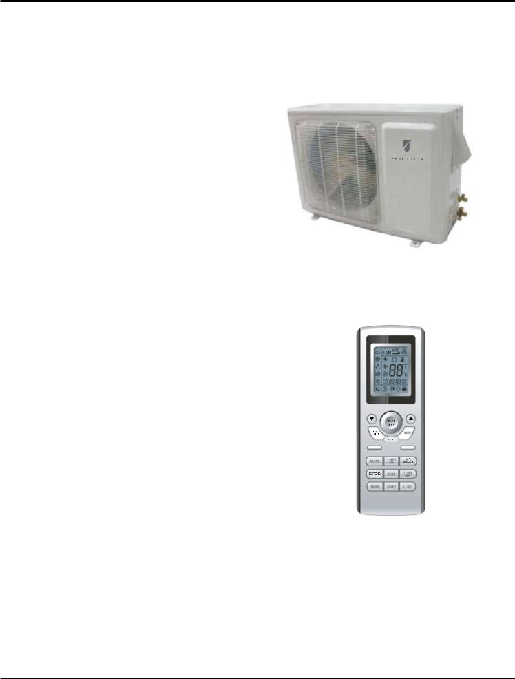
OutdoorUnit
MR09CIH
MR012CIH
Remote control windo w
YB1FAF
4
IMPORTANT SAFETY INFORMATION
The information contained in this manual is intended for use by a qualified service technician who is familiar with the safety procedures required for installation and repair, and who is equipped with the proper tools and test instruments required to service this product.
Installation or repairs made by unqualifi ed persons can result in subjecting the unqualifi ed person making such repairs as well as the persons being served by the equipment to hazards resulting in injury or electrical shock which can be serious or even fatal.
Safety warnings have been placed throughout this manual to alert you to potential hazards that may be encountered. If you install or perform service on equipment, it is your responsibility to read and obey these warnings to guard against any bodily injury or property damage which may result to you or others.
Your safety and the safety of others are very important.
We have provided many important safety messages in this manual and on your appliance. Always read, understand and obey all safety messages.
This is a safety Alert symbol.
This symbol alerts you to potential hazards that can kill or hurt you and others.
All safety messages will follow the safety alert symbol with the word “WARNING” or “CAUTION”.
These words mean:

 WARNING

 CAUTION
You can be killed or seriously injured if you do not follow instructions.
You can receive minor or moderate injury if you do not follow instructions.
All safety messages will tell you what the potential hazard is, tell you how to reduce the chance of injury, and tell you what will happen if the instructions are not followed.
|
A message to alert you of potential property damage will have the word “NOTICE”. |
|
NOTICE |
||
Potential property damage can occur if instructions are not followed. |
||
|
||
|
|
PERSONAL INJURY OR DEATH HAZARDS
ELECTRICAL HAZARDS:
•Unplug and/or disconnect all electrical power to the unit before performing inspections, maintenance, or service.
•Make sure to follow proper lockout/tag out procedures.
•Always work in the company of a qualifi ed assistant if possible.
•Capacitors, even when disconnected from the electrical power source, retain an electrical charge potential capable of causing electric shock or electrocution.
•Handle, discharge, and test capacitors according to safe, established, standards, and approved procedures.
•Extreme care, proper judgment, and safety procedures must be exercised if it becomes necessary to test or troubleshoot equipment with the power on to the unit.
5
•Do not spray or pour water on the return air grille, discharge air grille, evaporator coil, control panel, and sleeve on the room side of the air conditioning unit while cleaning.
•Electrical component malfunction caused by water could result in electric shock or other electrically unsafe conditions when the power is restored and the unit is turned on, even after the exterior is dry.
•Never operate the A/C unit with wet hands.
•Use air conditioner on a single dedicated circuit within the specifi ed amperage rating.
•Use on a properly grounded outlet only.
•Do not remove ground prong of plug.
•Do not cut or modify the power supply cord.
•Do not use extension cords with the unit.
•Follow all safety precautions and use proper and adequate protective safety aids such as: gloves, goggles, clothing, adequately insulated tools, and testing equipment etc.
•Failure to follow proper safety procedures and/or these warnings can result in serious injury or death.
REFRIGERATION SYSTEM REPAIR HAZARDS:
•Use approved standard refrigerant recovering procedures and equipment to relieve pressure before opening system for repair.
•Do not allow liquid refrigerant to contact skin. Direct contact with liquid refrigerant can result in minor to moderate injury.
•Be extremely careful when using an oxy-acetylene torch. Direct contact with the torch’s fl ame or hot surfaces can cause serious burns.
•Make sure to protect personal and surrounding property with fi re proof materials.
•Have a fi re extinguisher at hand while using a torch.
•Provide adequate ventilation to vent off toxic fumes, and work with a qualifi ed assistant whenever possible.
•Always use a pressure regulator when using dry nitrogen to test the sealed refrigeration system for leaks, fl ushing etc.
•Make sure to follow all safety precautions and to use proper protective safety aids such as: gloves, safety glasses, clothing etc.
•Failure to follow proper safety procedures and/or these warnings can result in serious injury or death.
MECHANICAL HAZARDS:
•Extreme care, proper judgment and all safety procedures must be followed when testing, troubleshooting, handling, or working around unit with moving and/or rotating parts.
•Be careful when, handling and working around exposed edges and corners of the sleeve, chassis, and other unit components especially the sharp fi ns of the indoor and outdoor coils.
•Use proper and adequate protective aids such as: gloves, clothing, safety glasses etc.
•Failure to follow proper safety procedures and/or these warnings can result in serious injury or death.
6
PROPERTY DAMAGE HAZARDS
FIRE DAMAGE HAZARDS:
•Read the Installation/Operation Manual for the air conditioning unit prior to operating.
•Use air conditioner on a single dedicated circuit within the specifi ed amperage rating.
•Connect to a properly grounded outlet only.
•Do not remove ground prong of plug.
•Do not cut or modify the power supply cord.
•Do not use extension cords with the unit.
•Be extremely careful when using acetylene torch and protect surrounding property.
•Failure to follow these instructions can result in fi re and minor to serious property damage.
WATER DAMAGE HAZARDS:
•Improper installation, maintenance or servicing of the air conditioner unit can result in water damage to personal items or property.
•Insure that the unit has a suffi cient pitch to the outside to allow water to drain from the unit.
•Do not drill holes in the bottom of the drain pan or the underside of the unit.
•Failure to follow these instructions can result in damage to the unit and/or minor to serious property damage.
7
Specifi cations
Model |
|
|
|
|
|
|
Outdoor Unit MR09C1H |
|
|
|
|
|
|
|
MW09CIH |
||
Function |
|
|
|
|
COOLING |
|||
Rated Voltage |
|
|
|
|
115V~ |
|||
Frequency |
|
High |
Hz |
70 |
|
|||
(Inverter different Compressor |
Standard |
Hz |
41 |
|
||||
speed) |
|
|
|
Low |
Hz |
15 |
|
|
Total Capacity |
|
High |
W / Btu/h |
3100/10600 |
|
|||
(Inverter different Compressor |
Standard |
W / Btu/h |
2650/9000 |
|
||||
speed) |
|
|
|
Low |
W / Btu/h |
1300/4435 |
|
|
Power Input |
|
High |
W |
1050 |
|
|||
(Inverter different Compressor |
Standard |
W |
640 |
|
||||
speed) |
|
|
|
Low |
W |
180 |
|
|
Rated Input |
|
High |
W |
1050 |
|
|||
|
|
|
|
|
|
|||
Standard |
W |
640 |
|
|||||
|
|
|
|
|||||
Rated Current |
|
High |
A |
16.8 |
|
|||
|
|
|
|
|
|
|||
Standard |
A |
7.0 |
|
|||||
|
|
|
|
|||||
|
|
|
|
|
|
|
|
|
|
|
|
|
Turbo |
|
330 |
|
|
|
|
|
|
SH |
|
CFM |
|
|
|
|
|
|
|
|
|||
Air Flow Volume |
|
H |
CFM |
294 |
|
|||
|
|
|
|
M |
CFM |
253 |
|
|
|
|
|
|
L |
CFM |
218 |
|
|
Dehumidifying Volume |
|
|
|
pints/hour |
1.69 |
|
||
STD |
|
|
|
|
|
W/W |
14.0 |
|
|
|
|
|
|
|
|
22 |
|
Indoor |
unit |
|
|
|
|
MW09CIH |
||
Fan Motor |
|
Turbo |
r/min |
1260 |
|
|||
|
SH |
|
||||||
|
|
Speed |
|
H |
r/min |
1050 |
|
|
|
|
|
M |
r/min |
920 |
|
||
|
|
|
|
|
||||
|
|
|
|
L |
r/min |
730 |
|
|
|
|
Output |
|
|
|
W |
20 |
|
|
|
Capacitor |
|
|
|
F |
4.0 |
|
|
|
RLA |
|
|
|
A |
0.38 |
|
Fan |
|
Type |
|
|
|
|
Cross flow fan |
|
|
|
Diameter-Length |
|
|
|
in. |
3.62 X 25.4 |
|
Evaporator |
|
|
|
|
Aluminum fin-copper tube |
|||
|
Pipe Diameter |
|
in. |
216 |
|
Row-Fin Gap |
|
in. |
0.019 - 0.055 |
|
width (L) |
|
in. |
25.4 X 1 X 10.5 |
|
|
|
|
|
Swing |
Model |
|
|
MP24AA |
Motor |
Output |
|
W |
2.4 |
Fuse (A) |
|
|
A |
PCB 3.15A |
Sound Pressure Level |
H |
dB (A) |
34 |
|
|
|
M |
dB (A) |
30 |
|
|
L |
dB (A) |
26 |
Sound Power Level |
H |
dB (A) |
44 |
|
|
|
M |
dB (A) |
40 |
|
|
L |
dB (A) |
36 |
|
|
|
in. |
33 1/433.X3X107/8.8X117 1/8 |
|
|
|
in. |
36X10X14 |
Net Weight /Gross Weight |
|
lbs |
16X2422.3X130.9 |
|
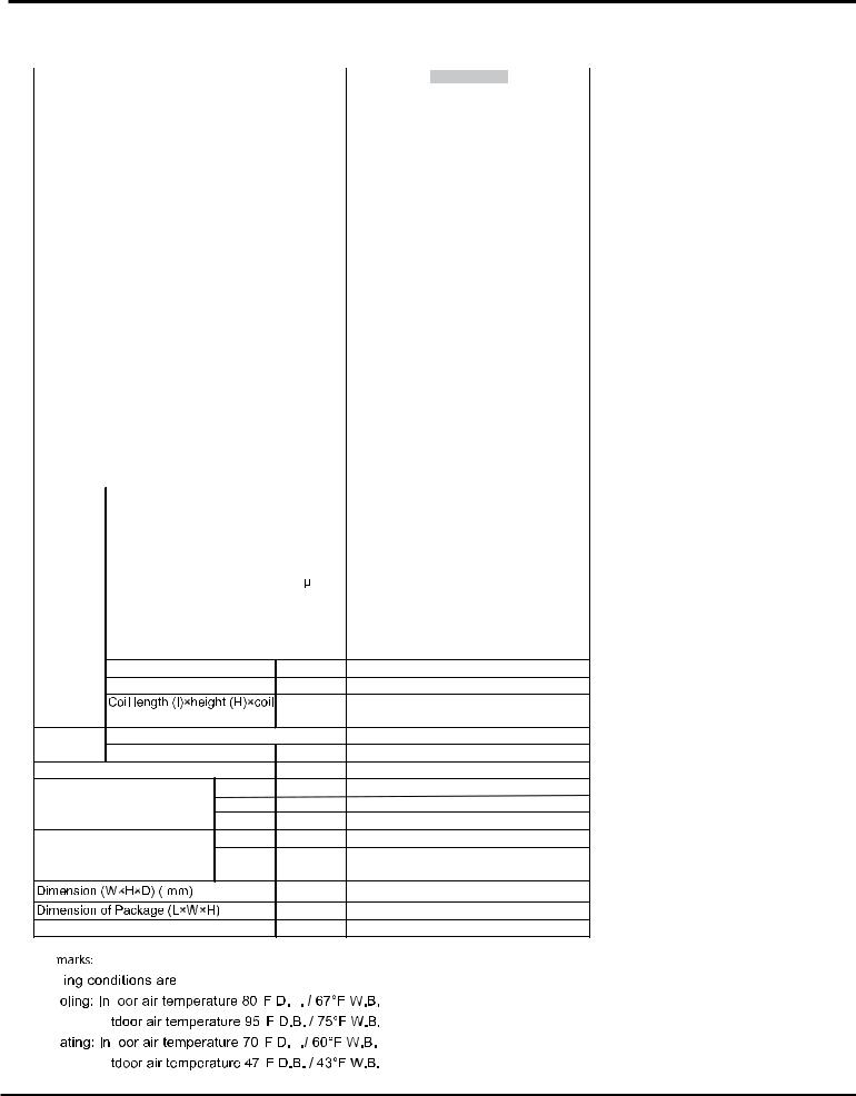
 Remark:s

 Rating conditions
 are:
are:
 Cooling:
 Indoor air temperature
 80¡F
80¡F D.B. / 67¡F W.B.
 Outdoor air temperature
 95.0¡F D.B. / 75¡F W.B.
 Heating:
 Indoor air temperature
 70¡F
70¡F D.B./ 60¡F W.B.
 Outdoor air temperature
 47¡F D.B. / 43¡F W.B.
8
Specifications
12K of 115V Models
Model |
|
|
|
|
|
|
|
|
|
|
|
Outdoor |
Unit MR12CH |
- SYSTEM |
||
|
|
|
|
|
|
|
|
|
|
|
|
MW12CIH |
|
|||
Function |
|
|
|
|
|
COOLING |
||||||||||
Rated Voltage |
|
|
|
|
|
208115-230V~ |
||||||||||
Frequency |
|
High |
|
Hz |
70 |
|
||||||||||
(Inverter different Compressor |
Standard |
|
Hz |
41 |
|
|||||||||||
speed) |
|
|
|
|
|
|
|
|
Low |
|
Hz |
15 |
|
|||
Total Capacity |
|
High |
|
W / Btu/h |
4100/14000 |
|||||||||||
(Inverter different Compressor |
Standard |
|
W / Btu/h |
3520/12000 |
||||||||||||
speed) |
|
|
|
|
|
|
|
|
Low |
|
W / Btu/h |
1320/4500 |
|
|||
Power Input |
|
High |
|
W |
1050 |
|
||||||||||
(Inverter different Compressor |
Standard |
|
W |
640 |
|
|||||||||||
speed) |
|
|
|
|
|
|
|
|
Low |
|
W |
180 |
|
|||
Rated Input |
|
High |
|
W |
1050 |
|
||||||||||
|
Standard |
|
W |
640 |
|
|||||||||||
|
|
|
|
|
|
|
|
|
|
|
|
|
||||
Rated Current |
|
High |
|
A |
6.5 |
|
||||||||||
|
Standard |
|
A |
3.2 |
|
|||||||||||
|
|
|
|
|
|
|
|
|
|
|
|
|
||||
|
|
|
|
|
|
|
|
|
|
|
Turbo |
|
CFM |
300 |
|
|
|
|
|
|
|
|
|
|
|
|
|
SH |
|
|
|||
Air Flow Volume |
|
H |
|
CFM |
277 |
|
||||||||||
|
|
|
|
|
|
|
|
|
|
|
M |
|
CFM |
253 |
|
|
|
|
|
|
|
|
|
|
|
|
|
|
|
|
|
|
|
|
|
|
|
|
|
|
|
|
|
|
L |
|
CFM |
218 |
|
|
|
|
|
|
|
|
|
|
|
|
|
|
|
|
|||
Dehumidifying Volume |
|
|
|
pints/hour |
2.54 |
|
||||||||||
EER / C.O.P |
|
|
|
W/W |
12. .00 |
|
||||||||||
SEER/HSPF |
|
|
|
|
22 |
|
||||||||||
|
|
|
|
|
|
|
|
|
|
|
|
|
|
|
|
|
Indoor |
unit |
|
|
|
|
|
|
|
||||||||
Fan Motor |
|
|
|
|
TurboSH |
|
r/min |
1260 |
|
|||||||
|
|
|
|
|
|
|
Speed |
|
H |
|
r/min |
1050 |
|
|||
|
|
|
|
|
|
|
|
M |
|
r/min |
920 |
|
||||
|
|
|
|
|
|
|
|
|
|
|
|
|
||||
|
|
|
|
|
|
|
|
|
|
|
L |
|
r/min |
730 |
|
|
|
|
|
|
|
|
|
Output |
|
|
|
W |
20 |
|
|||
|
|
|
|
|
|
|
Capacitor |
|
|
|
F |
1.0 |
|
|||
|
|
|
|
|
|
|
RLA |
|
|
|
A |
0.2 |
|
|||
Fan |
|
|
|
|
Type |
|
|
|
|
|
Cross flow fan |
|||||
|
|
|
|
|
|
|
Diameter-Length |
|
|
in. |
|
3.62X25.4 |
||||
Evaporator |
|
|
|
|
|
Aluminum fin-copper tube |
||||||||||
|
|
|
|
|
|
|
Pipe Diameter |
|
|
in. |
.276 |
|
||||
|
|
|
|
|
|
|
Row-Fin Gap |
|
|
in. |
.077-.055 |
|
||||
|
|
|
|
|
|
|
|
|
|
|
|
|
in. |
|
25.4X1X10.5 |
|
|
|
|
|
|
|
|
|
|
|
|
|
|
|
|||
|
|
|
|
|
|
|
width (L) |
|
|
|
||||||
|
|
|
|
|
|
|
|
|
|
|
|
|
|
|||
Swing |
|
|
|
|
Model |
|
|
|
|
|
MP24AA |
|||||
Motor |
|
|
|
|
Output |
|
|
|
W |
2.4 |
|
|||||
Fuse (A) |
|
|
|
A |
|
PCB 3.15A |
||||||||||
Sound Pressure Level |
|
H |
|
dB (A) |
34 |
|
||||||||||
|
|
|
|
|
|
|
|
|
|
|
M |
|
dB (A) |
30 |
|
|
|
|
|
|
|
|
|
|
|
|
|
L |
|
dB (A) |
26 |
|
|
Sound Power Level |
|
H |
|
dB (A) |
44 |
|
||||||||||
|
|
|
|
|
|
|
|
|
|
|
M |
|
dB (A) |
40 |
|
|
|
|
|
|
|
|
|
|
|
|
|
L |
|
dB (A) |
36 |
|
|
|
|
|
|
|
|
|
|
|
|
|
|
|
in. |
33 1/433X.3X107/8.3X77.11/8 |
||
|
|
|
|
|
|
|
|
|
|
|
|
|
in. |
|
36X10X14 |
|
Net Weight /Gross Weight |
|
|
lbs |
.2622.3/30.9 |
|
|||||||||||
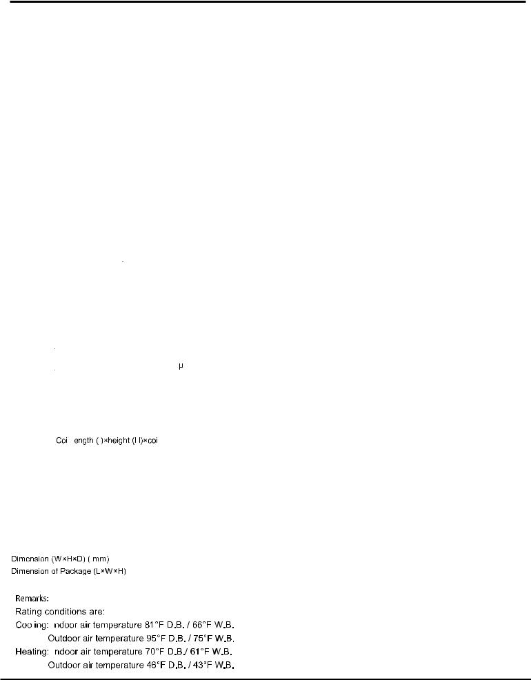
Remarks |
|
|
|
|
|
|
|
|||||||||
Rating conditions |
|
|
|
|
|
|
|
|||||||||
|
|
|
|
Indoor |
temperature |
|
|
.B. |
||||||||
|
|
Cooling: |
|
|
|
|
|
|||||||||
|
|
|
|
|
||||||||||||
|
|
|
|
|
|
|
Outdoor |
temperature |
|
|
.B. |
|||||
Heating: |
|
Indoor |
temperature |
|
|
.B. |
||||||||||
|
|
|
||||||||||||||
|
|
|
|
|
|
|
Outdoor |
temperature |
|
|
.B. |
|||||
9

Specifications
Outdoor Unit |
|
|
|
MR09C1H |
|
|
Manufacturer/trademark |
|
|
SANYO |
|
|
|
|
|
|
|
|
Model |
|
|
C-6RZ110H1A |
|
|
|
|
|
|
|
|
Type |
|
|
Twin rotory |
|
Compressor |
|
|
|
|
|
L.R.A. (A) |
A |
33 |
|
||
|
|
|
|
|
|
|
RLA(A) |
A |
4.59 |
|
|
|
|
|
|
|
|
|
Power Input(W) |
W |
800 |
|
|
|
|
|
|
|
|
|
Overload Protector |
|
|
Int11l-3979 |
|
|
|
|
|
|
|
Throttling Method |
|
Electronic Expansion Valve |
|||
|
|
throttling |
|||
|
|
|
|
||
|
|
|
|
|
|
Starting Method |
|
|
Transducer starting |
||
|
|
|
|
|
|
Working Temp Range |
F |
41 - 115 |
|
||
|
|
|
|
|
|
Heat |
Coil |
|
Aluminum fin-copper tube |
||
Exchanger |
|
|
|
|
|
Pipe Diameter |
mm |
.275 |
|
||
Coil |
|
||||
|
|
|
|
|
|
Rows-Fin Gap |
in. |
2 - .005 |
|
||
|
|
||||
|
|
|
|
|
|
Coil length (l) x height (H) x coil width (L) |
|
|
23.94 X 20 X 1.73 |
||
|
|
|
|
|
|
|
Speed |
rpm |
900/650 |
|
|
|
|
|
|
|
|
Fan Motor |
Output of Fan Motor |
W |
40 |
|
|
|
|
|
|
|
|
RLA |
A |
0.17 |
|
||
|
|
||||
|
|
|
|
|
|
|
Capacitor |
•F |
/ |
|
|
|
|
|
|
|
|
Air Flow Volume of Outdoor Unit |
CFM |
1118 |
|
||
|
|
|
|
|
|
Fan |
Type-Piece |
|
|
Axial fan - 1 |
|
|
|
|
|
|
|
Diameter |
in. |
15.7 |
|
||
|
|
||||
|
|
|
|
|
|
Defrosting Method |
|
/ |
|
||
|
|
|
|
|
|
Climate Type |
|
|
|
T1 |
|
|
|
|
|
|
|
Isolation |
|
|
|
I |
|
|
|
|
|
|
|
Moisture Protection |
|
|
IP24 |
||
|
|
|
|
|
|
Permissible Excessive Operating |
PSI |
552 |
|
||
Pressure for the Discharge Side |
|
||||
|
|
|
|
||
Permissible Excessive Operating |
PSI |
175 |
|
||
Pressure for the Suction Side |
|
||||
|
|
|
|
||
|
|
|
|
|
|
Sound Pressure Level |
dB (A) |
53 |
|
||
Sound Power Level |
dB (A) |
63 |
|
||
Dimension (W×H×D) |
in. |
|
|
||
|
33333/8.4XX2312.1/26 XX21.231/2 |
|
|||
|
|
|
|
|
|
Dimension of Package (L×W×H) |
in. |
|
34.6 X 14.2 X 22.3 |
||
|
|
|
|
|
|
Net Weight /Gross Weight |
lbs |
79.4/90.4 |
|
||
|
|
|
|
|
|
Refrigerant |
Name of refrigerant |
|
|
R410A |
|
|
|
|
|
|
|
Weight |
lbs |
2.65 |
|
||
|
|
||||
|
Factory Prescharge |
ft |
25 |
|
|
|
|
|
|
|
|
Connection |
Gas additional charge |
02/H |
.33 |
|
|
Pipe |
|
|
|
|
|
Liquid Pipe Diameter |
mm |
|
Φ6(1/4”) |
||
|
|
|
|
|
|
|
Gas Pipe Diameter |
mm |
|
Φ9(3/8”) |
|
|
|
|
|
|
|
Max. Interunit Height Difference |
ft |
33 |
|
||
|
|
|
|
|
|
Max. Interunit Piping Length |
ft |
66 |
|
||
|
|
|
|
|
|
The above data is subject to change without notice. Please refer to the nameplate of the unit.
10
Specifications
Outdoor Unit |
|
|
|
MR12C1H |
|
|
Manufacturer/trademark |
|
|
SANYO |
|
|
|
|
|
|
|
|
Model |
|
|
C-6RZ110H1A |
|
|
|
|
|
|
|
|
Type |
|
|
Twin rotory |
|
Compressor |
|
|
|
|
|
L.R.A. (A) |
A |
33 |
|
||
|
|
|
|
|
|
|
RLA(A) |
A |
4.59 |
|
|
|
|
|
|
|
|
|
Power Input(W) |
W |
800 |
|
|
|
|
|
|
|
|
|
Overload Protector |
|
|
Int11l-3979 |
|
|
|
|
|
|
|
Throttling Method |
|
Electronic Expansion Valve |
|||
|
|
throttling |
|||
|
|
|
|
||
|
|
|
|
|
|
Starting Method |
|
|
Transducer starting |
||
|
|
|
|
|
|
Working Temp Range |
F |
41 - 115 |
|
||
|
|
|
|
|
|
Heat |
Coil |
|
|
Aluminum fin-copper tube |
|
Exchanger |
|
|
|
|
|
Pipe Diameter |
mm |
.275 |
|
||
Coil |
|
||||
|
|
|
|
|
|
Rows-Fin Gap |
in. |
2 - .005 |
|
||
|
|
||||
|
|
|
|
|
|
Coil length (l) x height (H) x coil width (L) |
mm |
|
747X508X44 |
||
|
|
|
|
|
|
|
Speed |
rpm |
900/680 |
|
|
|
|
|
|
|
|
Fan Motor |
Output of Fan Motor |
W |
40 |
|
|
|
|
|
|
|
|
RLA |
A |
0.17 |
|
||
|
|
||||
|
|
|
|
|
|
|
Capacitor |
•F |
/ |
|
|
|
|
|
|
|
|
Air Flow Volume of Outdoor Unit |
CFM |
1118 |
|
||
|
|
|
|
|
|
Fan |
Type-Piece |
|
|
Axial fan |
|
|
|
|
|
|
|
Diameter |
in. |
15.7 |
|
||
|
|
||||
|
|
|
|
|
|
Defrosting Method |
|
/ |
|
||
|
|
|
|
|
|
Climate Type |
|
|
|
T1 |
|
|
|
|
|
|
|
Isolation |
|
|
|
I |
|
|
|
|
|
|
|
Moisture Protection |
|
|
IP24 |
||
|
|
|
|
|
|
Permissible Excessive Operating |
PSI |
552 |
|
||
Pressure for the Discharge Side |
|
||||
|
|
|
|
||
Permissible Excessive Operating |
PSI |
175 |
|
||
Pressure for the Suction Side |
|
||||
|
|
|
|
||
|
|
|
|
|
|
Sound Pressure Level |
dB (A) |
55 |
|
||
Sound Power Level |
dB (A) |
65 |
|
||
Dimension (W×H×D) |
in. |
|
|||
|
33 3/833X.423X 121/2.6XX1221.1/23 |
|
|||
|
|
|
|
|
|
Dimension of Package (L×W×H) |
in. |
|
34.6 X 14.2 X 22.3 |
||
|
|
|
|
|
|
Net Weight /Gross Weight |
lbs |
79.4/90.4 |
|
||
|
|
|
|
|
|
Refrigerant |
Name of refrigerant |
|
|
R410A |
|
|
|
|
|
|
|
Weight |
lbs |
2.65 |
|
||
|
|
||||
|
Factory Prescharge |
ft |
25 |
|
|
|
|
|
|
|
|
Connection |
Gas additional charge |
H |
|
1/4 oz per ft |
|
Pipe |
|
|
|
|
|
Liquid Pipe Diameter |
mm |
|
Φ6(1/4”) |
||
|
|
|
|
|
|
|
Gas Pipe Diameter |
mm |
|
Φ9(3/8”) |
|
|
|
|
|
|
|
Max. Interunit Height Difference |
ft |
33 |
|
||
|
|
|
|
|
|
Max. Interunit Piping Length |
ft |
66 |
|
||
|
|
|
|
|
|
The above data is subject to change without notice. Please refer to the nameplate of the unit.
11
Specifications
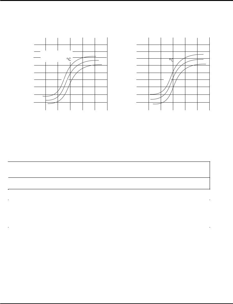
Appending date
Table showing operation frequency limits for cooling and heating
|
|
|
Outdoor Relative Humidity 40% |
|||||
|
140 |
|
|
|
|
|
|
|
(%) |
130 |
|
|
|
|
|
||
|
Indoor Wet Bulb |
|
59°F |
|
||||
Ratio |
120 |
|
Temperature( |
) |
|
68°F |
|
|
|
|
|
|
|||||
|
|
|
|
|
|
|
|
|
Change |
110 |
|
|
|
|
|
77°F |
|
|
|
|
|
|
|
|
||
100 |
|
|
|
|
|
|
|
|
|
|
|
|
|
|
|
|
|
Capacity |
80 |
|
|
|
|
|
|
|
60 |
|
|
|
|
|
|
|
|
|
|
|
|
|
|
|
|
|
|
40 |
|
|
|
|
|
|
|
|
20 |
|
|
|
|
|
|
|
|
|
|
|
|
|
|
|
|
|
|
15 |
35 |
55 |
75 |
95 |
|
|
|
|
|
Compressor Frequency(Hz) |
|||||
|
|
|
Outdoor Relative Humidity 72% |
||||||||
|
140 |
|
|
|
|
|
|
|
|
|
|
(%) |
130 |
|
|
|
|
|
|
|
|
59°F |
|
|
Indoor Wet Bulb |
|
|
||||||||
|
|
|
|
||||||||
Ratio |
120 |
|
Temperature( |
) |
|
|
60.8°F |
||||
|
|
|
|
||||||||
Change |
110 |
|
|
|
|
|
|
|
|
62.6°F |
|
|
|
|
|
|
|
|
|
||||
100 |
|
|
|
|
|
|
|
|
|
|
|
|
|
|
|
|
|
|
|
|
|
||
|
|
|
|
|
|
|
|
|
|
|
|
Capacity |
80 |
|
|
|
|
|
|
|
|
|
|
60 |
|
|
|
|
|
|
|
|
|
|
|
|
|
|
|
|
|
|
|
|
|
|
|
|
40 |
|
|
|
|
|
|
|
|
|
|
|
20 |
|
|
|
|
|
|
|
|
|
|
|
|
|
|
|
|
|
|
|
|
|
|
|
|
15 |
35 |
|
55 |
75 |
95 |
|
|||
|
|
|
Compressor Frequency(Hz) |
||||||||
Performance date for both cooling and heating
COOLING:
|
Temperature Condition |
|
Standard |
Heat exchanger pipe |
|
Outdoor fan |
Compressor |
||||||||
|
(°F) |
|
|
|
|
|
Model |
pressure |
temp. |
|
Indoor fan |
mode |
revolution |
||
|
|
Indoor |
Outdoor |
name |
P (MPa) |
EVP (°F)C |
OD(°F) |
mode |
|
(rps) |
|||||
|
|
|
|
|
|
|
|
09K |
0.8 to 1.1 |
53 to 57 |
105 to 104 |
Turbo |
High |
Rated |
|
|
|
80.80/6706/.92 |
|
|
95/– |
12K |
0.8 to 1.0 |
50 to 54 |
109 to 113 |
Turbo |
High |
Rated |
|||
|
|
|
|
||||||||||||
|
|
|
|
|
|
|
|
|
|
|
|
|
|
|
|
|
|
HEATING: |
|
|
|
|
|
|
|
|
|
||||
|
|
|
|
|
|
|
|
|
|
|
|
|
|
||
|
Temperature Condition |
|
Standard |
Heat exchanger pipe |
|
|
Compressor |
||||||||
|
(°F) |
|
|
|
|
|
|
|
temp. |
|
|
|
|||
|
|
|
|
|
|
Model |
pressure |
|
Indoor fan |
Outdoor fan |
revolution |
||||
|
|
Indoor |
Outdoor |
name |
P (MPa) |
EVP (°F) |
COD(°C) |
mode |
mode |
(rps) |
|||||
|
|
|
|
|
|
|
|
09K |
2.8 to 3.2 |
99 to 100 |
2 to 4 |
Turbo |
High |
Rated |
|
|
|
|
|
|
|
|
|
||||||||
|
66.67/6098/ |
.08 |
|
46.47/4399/ 2.99 |
|
||||||||||
|
|
|
|
|
|
|
|
|
|
||||||
12K |
2.8 to 3.2 |
108 to 111 |
0 to 3 |
Turbo |
High |
Rated |
|||||||||
|
|
|
|
|
|
|
|
||||||||
|
|
|
|
|
|
|
|
||||||||
NOTES :
(1)Measure surface temperature of heat exchanger pipe around center of heat exchanger path U bent. (Thermistor themometer)
(2)Connecting piping condition : 7.6 m
12
Specifications
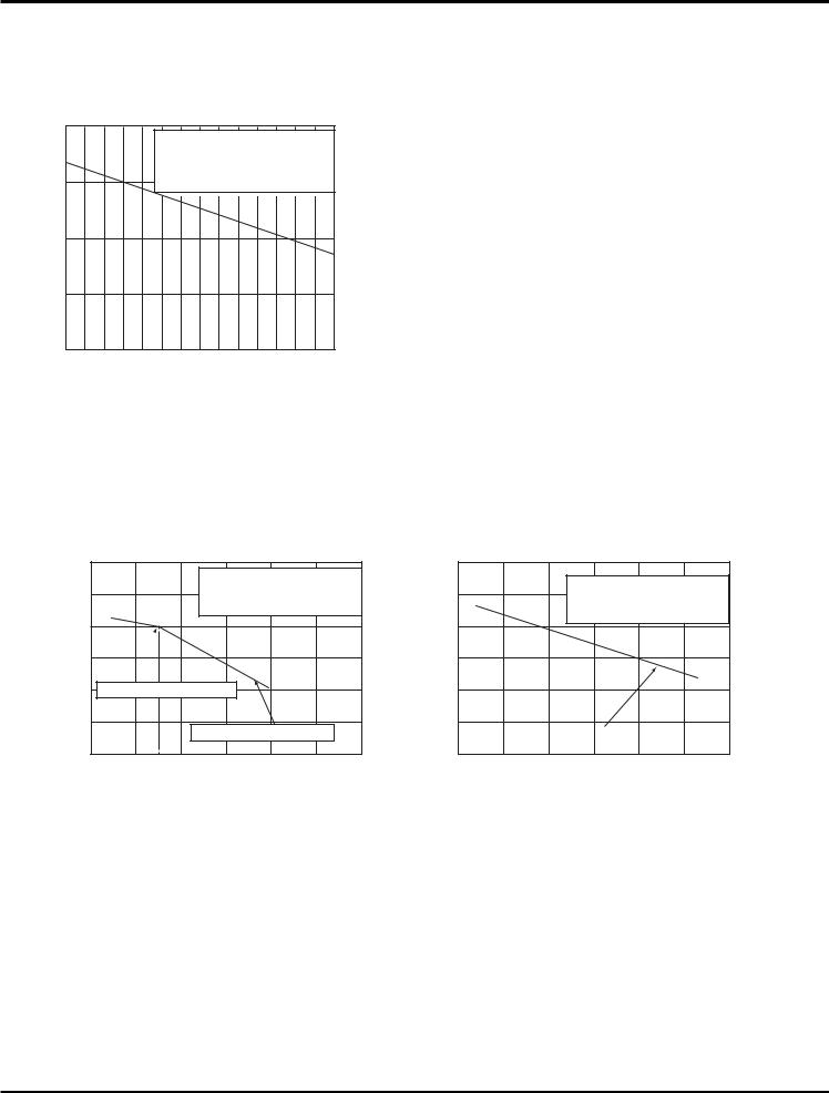
Expanded capacity data tables for both cooling and heating
Cooling
Capacity Ratio (%)
110 |
|
|
• Conditions |
|
Indoor: DB80°F/WB67°F.06˚F/WB66.92˚F |
100 |
Indoor air flow : TURBO |
Pipe length : 7.6m |
|
90 |
|
80 |
|
70
90 |
91 |
93 |
95 |
97 |
99 |
100 |
102 |
104 |
106 |
108 |
111 |
113 |
115 |
Outdoor temp. (˚F)
Capacity Variation Ratio According to Pipe Length
110
•Conditions
Indoor: DB80°F/WB67°F
105 |
Outdoor: DB95°F/WB75°F |
Indoor air flow: TURBO
100 |
|
|
|
|
|
95 |
|
|
|
|
|
90 |
Standard pipe length 7.6m |
|
|
|
|
85 |
|
|
|
|
|
|
|
Maximum pipe length 20m |
|
||
80 |
|
|
|
|
|
05 |
10 |
15 |
20 |
25 |
30 |
Total pipe length (m)
110 |
|
|
|
|
|
|
|
|
|
|
|
• Conditions |
|
|
|
105 |
|
|
|
Indoor: DB80°F/WB67°F |
|
|
|
|
|
|
|
Outdoor: DB95°F/WB75°F |
|
||
|
|
|
|
Indoor air flow: TURBO |
|
||
100 |
|
|
|
|
|
|
|
95 |
|
|
|
|
|
|
|
90 |
|
|
|
|
|
|
|
85 |
|
Maximum Elevation 7.6m |
|
|
|
||
|
|
|
|
|
|||
80 |
01 |
.5 |
3.04 |
.5 |
6.07 |
.5 |
9.0 |
Total Elevation (m)
13
Specifications
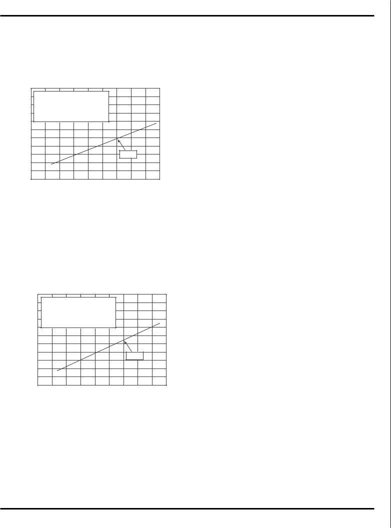
Operation Characteristic Curve
Cooling |
9 btu unit |
|
|
25.0 |
• Conditions |
|
|
|
|
|
|
|
|
|
22.5 |
Indoor: DB80°F/WB67°F |
|
|
|
|
|
|
||
|
Outdoor: DB95°F/WB75°F |
|
|
|
|
|
||||
|
|
|
|
|
|
|
||||
|
20.0 |
Indoor air flow : TURBO |
|
|
|
|
|
|||
|
Pipe lengt: 7.6m |
|
|
|
|
|
|
|||
(A) |
|
|
|
|
|
|
|
|||
17.5 |
|
|
|
|
|
|
|
|
|
|
|
|
|
|
|
|
|
|
|
|
|
Current |
15.0 |
|
|
|
|
|
|
|
|
|
12.5 |
|
|
|
|
|
|
|
|
|
|
10.0 |
|
|
|
|
|
|
|
|
|
|
|
7.5 |
|
|
|
|
|
115V |
|
|
|
|
5.0 |
|
|
|
|
|
|
|
|
|
|
2.5 |
|
|
|
|
|
|
|
|
|
|
0 |
|
|
|
|
|
|
|
|
|
|
01 |
02 |
03 |
04 |
05 |
06 |
07 |
09 |
80 |
0 |
Compressor speed (rps)
|
|
|
1 2 Ko12f11btu5 VUunitn i ts |
|
|
|
|
|||
Cooling |
|
|
|
|
|
|
|
|
|
|
|
25.0 |
• Conditions |
|
|
|
|
|
|
|
|
|
22.5 |
Indoor: DB80: °F/WB67°F |
|
|
|
|
|
|
||
|
Outdoor: DB95°F/WB75°F |
|
|
|
|
|
|
|||
|
|
|
|
|
|
|
|
|||
|
20.0 |
Indoor air flow : TURBO |
|
|
|
|
|
|||
|
Pipe length: 7.6m |
|
|
|
|
|
|
|||
(A) |
|
|
|
|
|
|
|
|||
17.5 |
|
|
|
|
|
|
|
|
|
|
15.0 |
|
|
|
|
|
|
|
|
|
|
Current |
|
|
|
|
|
|
|
|
|
|
12.5 |
|
|
|
|
|
|
|
|
|
|
10.0 |
|
|
|
|
|
115V |
|
|
||
|
|
|
|
|
|
|
|
|||
|
7.5 |
|
|
|
|
|
|
|
||
|
|
|
|
|
|
|
|
|
|
|
|
5.0 |
|
|
|
|
|
|
|
|
|
|
2.5 |
|
|
|
|
|
|
|
|
|
|
0 |
|
|
|
|
|
|
|
|
|
|
01 |
02 |
03 |
04 |
05 |
06 |
07 |
09 |
80 |
0 |
Compressor speed (rps)
14

Specifications
2.5 Noise criteria curve tables for both models
Noise/dB(A)
40
35
30
25
|
|
|
|
0 9 KU n i ts |
|
|
|
|
|
|
|
|
|
|
|
|
09 btu units |
|
|
|
|
|
|
|
|
|
|
|
|
|
|
70 |
|
|
|
|
|
|
|
Indoor side noise when blowing |
|
|
|
Outdoor side noise |
|
|
|
||||
|
|
|
|
|
|
|
||||||
|
|
|
|
|
|
|
|
|||||
|
|
|
|
|
|
60 |
|
|
|
|
|
|
|
|
|
|
|
|
|
|
|
|
|
|
|
|
|
|
|
|
|
|
|
|
|
|
|
|
|
|
|
|
|
Noise/dB(A) |
50 |
|
|
|
|
|
|
|
|
|
|
|
|
|
|
|
|
|
||
|
|
|
|
|
40 |
|
|
|
|
|
|
|
|
|
|
|
|
|
|
|
|
|
|
|
|
|
|
|
|
|
|
30 |
|
|
|
|
|
|
|
|
|
|
|
|
|
|
|
|
|
|
|
|
|
|
|
|
|
|
|
|
|
|
|
|
Low |
MiddleH |
igh |
Turbo |
|
|
|
|
|
|
|
||
|
|
|
|
|
|
20 |
|
|
|
|
|
|
|
|
|
|
|
|
|
|
|
|
|
|
|
|
Indoor fan motor rotating speed |
|
|
0 |
20 |
40 |
60 |
80 |
100 |
|||
Compressor frequency/Hz
Noise/dB(A)
40
35
30
25
20
|
|
|
|
1 2 KU n i ts |
|
|
|
|
|
|
|
|
|
|
|
|
|
12 btu unit |
|
|
|
|
|
|
|
|
|
|
|
|
|
|
70 |
|
|
|
|
|
|
||
|
Indoor side noise when blowing |
|
|
|
|
Outdoor side noise |
|
|
|
||||
|
|
|
|
|
|
|
|
||||||
|
|
|
|
|
|
60 |
|
|
|
|
|
|
|
|
|
|
|
|
|
|
|
|
|
|
|
|
|
|
|
|
|
|
|
|
|
|
|
|
|
|
|
|
|
|
|
|
Noise/dB(A) |
50 |
|
|
|
|
|
|
|
|
|
|
|
|
|
|
|
|
|
|
|
||
|
|
|
|
|
40 |
|
|
|
|
|
|
|
|
|
|
|
|
|
|
|
|
|
|
|
|
|
|
|
|
|
|
|
|
30 |
|
|
|
|
|
|
|
|
|
|
|
|
|
|
|
|
|
|
|
|
|
|
|
|
|
|
|
|
|
|
|
|
|
|
|
Low |
MiddleH |
igh |
Turbo |
|
|
|
|
|
|
|
|
||
|
|
|
|
|
|
20 |
|
|
|
|
|
|
|
|
|
|
|
|
|
|
|
|
|
|
|
|
|
|
Indoor fan motor rotating speed |
|
|
0 |
20 |
40 |
60 |
80 |
100 |
||||
Compressor frequency/Hz
15
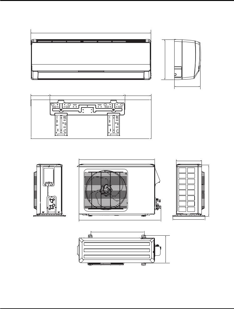
Constrction views
3.Construction Views
3.1Indoor Unit
W
H
D
5131/45 |
21542 |
6163/49 |
Unit:m m
3.2 Outdoor Unit
W2 |
D4 |
|
H2
W3
D2
W4
D3
System |
|
Indoor Unit (mm) |
|
|
|
|
Outdoor Unit (mm) |
|
|
|
|||||||
|
|
|
|
|
|
|
|
|
|
|
|
|
|
||||
Model |
|
|
Cabinet |
|
|
Cabinet |
|
|
|
|
Additional Dimensions |
|
|||||
Number |
|
|
|
|
|
|
|
|
|
|
|
|
|
|
|||
|
|
|
|
W |
|
H |
|
D |
W2 |
H2 |
D4 |
|
D2 |
|
W3 |
D3 |
W4 |
|
|
|
|
|
|
|
|
|
|
|
|
|
|
|
|
|
|
|
|
|
|
|
|
|
|
|
|
|
|
|
|
|
|
|
|
|
09K |
|
|
|
|
|
|
|
|
|
|
|
|
|
|
||
|
0 |
9K |
|
33 1/4 |
|
10 7/8 |
|
7 1/8 |
30 3/4 |
23 1/2 |
10 7/8 |
|
12 1/2 |
|
33 3/8 |
11 |
21 1/2 |
|
|
|
|
|
|
|
|||||||||||
|
12K |
|
|
|
|
||||||||||||
|
1 |
2K |
|
|
|
|
|
|
|
|
|
|
|
|
|
|
|
16
Refrigerant System Diagram
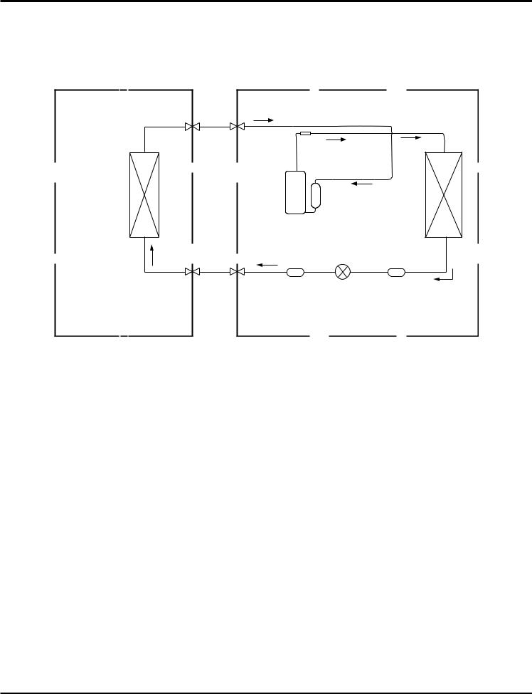
4. Refrigerant System Diagram
Cooling Models
INDOOR UNIT |
OUTDOOR UNIT |
GAS SIDE
3-WAY VALVE
HEAT EXCHANGE (EVAPORATOR)
Muffler |
|
Discharge |
|
Suction |
Accumlator |
COMPRESSOR |
|
HEAT EXCHANGE (CONDENSER)
LIQUID SIDE |
|
|
2-WAY VALVE |
Strainer |
Electric Expansion Strainer |
|
|
Valve |
 COOLING
17
Schematic Diagram
5.Schematic Diagram
5.1Electrical Date
 Indoor Unit
Symbol |
Color symbol |
Symbol |
Color symbol |
|
|
|
|
WH |
WHITE |
BN |
BROWN |
|
|
|
|
YE |
YELLOW |
BU |
BLUE |
|
|
|
|
RD |
RED |
BK |
BLACK |
|
|
|
|
YEGN |
YELLOW GREEN |
|
PROTECTIVE EARTH |
|
|
|
|
 Outdoor Unit
Symbol |
Parts name |
Symbol |
Color symbol |
|
|
|
|
L1 |
REACROR |
WH |
WHITE |
|
|
|
|
PCB1~PCB2 |
PRINTED CIRCUIT BOARD |
YE |
YELLOW |
|
|
|
|
S10/S11S40/S70/S80/S90 |
CONNECTOR |
RD |
RED |
|
|
|
|
SAT |
OVERLOAD |
BN |
SAT OVERLOAD BN BROWN |
|
|
|
|
COMP |
COMPRESSOR |
BU |
BLUE |
|
|
|
|
|
PROTECTIVE EARTH |
BK |
BLACK |
|
|
|
|
|
|
YEGN |
YELLOW GREEN |
|
|
|
|
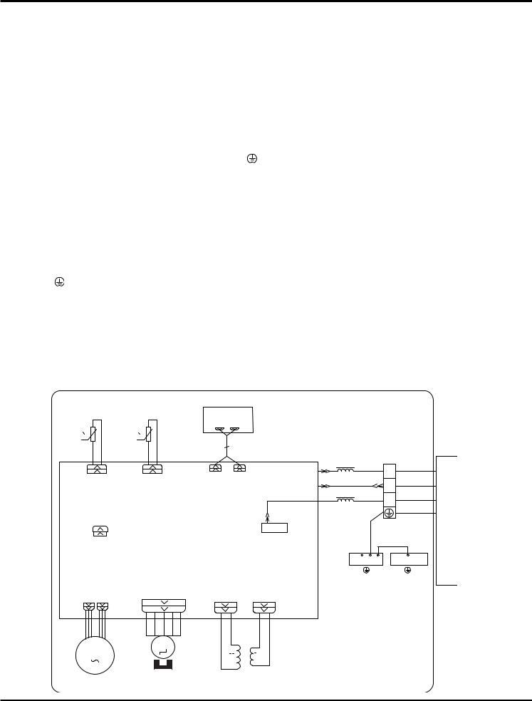
5.2 Electrical wiring
These circuit diagrams are subject to change without notice, please refer to the one supplied with the unit.
 Indoor Unit
ROOM |
TUBE |
DISPLAY |
TEM.SENSOR |
TEM.SENSOR |
AP1 |
|
|
|
|
|
CN1 CN2 |
00
RT1 |
RT2 |
|
13 |
|
|
|
|
|
|
|
|
|
XT1 |
|
|
|
|
N |
W4 BU |
|
|
|
DISP-1 |
DISP-2 |
L1 |
N(1) |
|
|
|
|
|
|||
ROOM |
TUBE |
COM-OUT |
W5 BK |
|
||
|
|
2 |
||||
|
|
|
|
|
||
|
|
|
|
|
|
|
|
|
|
|
|
W3 BN |
3 |
|
|
|
|
|
L1 |
|
|
|
|
|
|
|
|
CAP |
|
|
|
|
W2 YEGN |
|
|
AP2 |
|
AC-L |
L-OUT |
||
|
|
|
K4 |
|
W1 YEGN |
|
JUMP |
|
|
|
|
||
|
|
|
|
|
|
|
|
|
|
|
|
EVAPORATOR |
ELECTRIC BOX |
|
|
|
|
|
G |
G |
PGF PG |
SWING-UD |
TR_OUT TR_IN |
|
|
|
|
|
|
|
|
|||
TC
M2
M1
II I
OUTDOOR UNIT
FAN MOTOR |
SWING MOTOR(U.D) |
TRANSFORMER |
18
Schematic Diagram
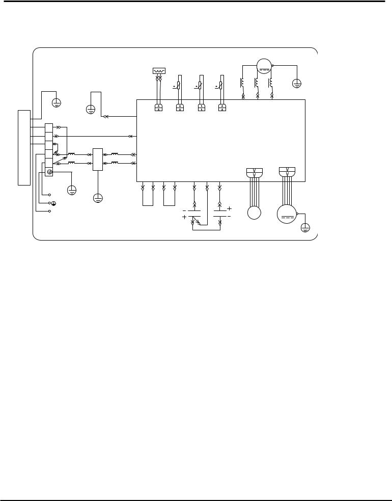
 OUTDOOR UNIT
Cooling Models of 115V
|
|
|
|
|
|
|
|
|
|
|
|
COMP |
|
|
|
|
CT1,2 |
TUBE |
OUTROOM EXHUAST |
|
|
R COMP E |
|||
|
|
|
|
TEM.SENSOR TEM.SENSORTEM.SENSOR |
|
S |
C |
|||||
|
|
|
|
|
|
|
|
|
|
|
||
|
|
|
|
|
|
|
|
|
|
|
|
|
|
|
|
|
|
RT3 |
RT4 |
RT5 |
|
L2 |
|
L2 |
L2 |
|
|
W3YEGN |
|
W10 RD |
0 |
0 |
0 |
|
|
|||
|
|
|
W5 BU |
W6 YE |
W7 BK |
|||||||
|
|
|
|
|
|
|
|
|||||
|
|
|
|
|
|
|
|
|
|
U |
V |
W |
I |
|
G |
|
OVERHEAT |
OUTTUBE |
OUTROOM EXHAUST |
|
|
|
|
||
XT2 |
G |
E |
|
|
|
|
||||||
|
|
|
|
|
|
|
|
|
|
|||
NW15 BU
DN(1)
O |
2 |
|
|
|
|
W4 BK |
|
COMU |
|
|
|
|
|
|
|
|
|
|
|
|
|
|
|
|
|||
O |
3 |
W14 BN |
|
FILTER |
|
|
|
|
|
|
AP1 |
|
|
R |
L1 |
|
L4 |
|
|
|
|
|
|
|
|||
L |
W1 BN |
1 |
3 |
W17 RD |
AC-L1 |
|
|
|
|
|
|||
|
L1 |
|
L4 |
|
|
|
|
|
|||||
U |
N |
W2BU |
2 |
4 |
W16 WH |
AC-N1 |
|
|
|
|
CN1 |
||
N |
|
|
|
|
E |
|
|
|
|
|
|
|
|
I |
|
W13 YEGN |
|
|
|
|
|
AC-N3AC-N4AC-L3 AC-L2 |
AC-N5 |
AC-L2 AC-L4 |
|
||
T |
|
|
|
|
|
|
|
||||||
|
|
|
|
|
|
|
|
|
|
|
|
|
|
|
POWER |
|
|
W18 YEGN |
|
|
|
|
|
|
|
||
|
|
N |
G |
|
|
|
|
|
|
W20 BU W23 OG W21 BN |
|
||
|
|
|
|
|
|
|
|
|
|
|
|
|
|
|
|
|
|
|
G |
|
|
W19 BU |
W24 RD |
C3 |
|
C4 |
|
|
|
L |
|
|
|
|
|
1 |
2 |
|
|||
|
|
|
|
|
|
|
|
EKV |
|||||
|
|
|
|
|
|
|
|
|
|
|
2 |
1 |
|
|
|
|
|
|
|
|
|
|
|
|
|
||
W22 WH
W8 YEGN
G
OFAN
M
FAN MOTOR
G
19

Schematic Diagram
5.3 PRINTED CIRCUIT BOARD
TOP VIEW |
|
|
|
|
1 |
|
|
4 |
|
2 |
3 |
|
|
|
|
5 |
6 |
||
|
|
|
||
|
|
|
|
7 |
|
|
|
12 |
|
|
|
|
|
8 |
|
11 |
|
|
|
|
|
|
|
9 |
|
|
|
|
10 |
 BOTTOM VIEW
1 |
Interface of neutral wire |
|
|
2 |
Transformer input |
|
|
3 |
Interface of PG motor |
|
|
4 |
Auto button |
|
|
5 |
Feedback from PG motor |
|
|
6 |
Up&Down swing |
|
|
7 |
Jumper cap |
|
|
8 |
Indoor temperature sensor |
|
|
9 |
Pipe temperature sensor |
|
|
10 |
DISP-1, DISP-2 display interface |
|
|
11 |
Protective tube |
|
|
12 |
Communication interface |
|
|
20
Schematic Diagram
 TOP VIEW
Terminal of jump wire, live wire and
neutral wire, AC-N4 joint
AC-N3, |
|
External connect high- |
|
|
|
|
|
|
|
|
|
|
|
|
|
|
|
|
|
|
|
|
|
|
|
|
|
|
|
|
|
|
|
|
|||||||||||||||||||||||||||||||||||||||||
AC-L2 joint |
|
|
|
|
|
|
|
|
|
|
|
|
|
|
|
|
|
|
|
|
|
|
|
|
|
|
|
|
|
|
|
|
|
||||||||||||||||||||||||||||||||||||||||||
|
capacity positive terminal |
External connect high- |
|
|
|
|
|
|
|
|
|
|
|
|
|
|
|
||||||||||||||||||||||||||||||||||||||||||||||||||||||||||
AC-L3 |
|
|
|
|
|
|
|
|
|
|
|
|
|
|
|
|
|
|
|
|
|
|
|
|
|
|
|
|
|
|
|
|
|
|
|
|
|
|
|
|
|
|
|
|
|
||||||||||||||||||||||||||||||
|
|
|
|
|
|
|
|
|
|
|
|
|
|
|
|
|
|
|
|
|
|
|
|
|
|
|
|
|
|
capacity negative |
|
|
|
|
|
|
|
|
|
|
|
|
|
|
|
||||||||||||||||||||||||||||||
|
|
|
|
|
|
|
|
|
|
|
|
|
|
|
|
|
|
|
|
|
|
|
|
|
|
|
|
|
Protective |
|
|
|
|
|
|
|
|
|
|
|
|
|
|
|
|||||||||||||||||||||||||||||||
|
|
|
|
|
|
|
|
|
|
|
|
|
|
|
|
|
|
|
|
|
|
|
|
|
|
|
|
|
|
tube |
terminal |
|
|
|
|
|
|
|
|
|
|
|
|
|
|
|
|||||||||||||||||||||||||||||
|
|
|
|
|
|
|
|
|
|
|
|
|
|
|
|
|
|
|
|
|
|
|
|
|
|
|
|
|
|
|
|
|
|
|
|
|
|
|
|
|
|
|
|
|
|
|
|
|
|
|
|
|
|
|
|
|
|
|
|
|
|
|
|
|
|
|
|
|
|
|
|
|
|
|
|
|
|
|
|
|
|
|
|
|
|
|
|
|
|
|
|
|
|
|
|
|
|
|
|
|
|
|
|
|
|
|
|
|
|
|
|
|
|
|
|
|
|
|
|
|
|
|
|
|
|
|
|
|
|
|
|
|
|
|
|
|
|
|
|
|
|
|
|
|
|
|
|
|
|
|
|
|
|
|
|
|
|
|
|
|
|
|
|
|
|
|
|
|
|
|
|
|
|
|
|
|
|
|
|
|
|
|
|
|
|
|
|
|
|
|
|
|
|
|
|
|
|
|
|
|
|
|
|
|
|
|
|
|
|
|
|
|
|
|
|
|
|
|
|
|
|
|
|
|
|
|
|
|
|
|
|
|
|
|
|
|
|
|
|
|
|
|
|
|
|
|
|
|
|
|
|
|
|
|
|
|
|
|
|
|
|
|
|
|
|
|
|
|
|
|
|
|
|
|
|
|
|
|
|
|
|
|
|
|
|
|
|
|
|
|
|
|
|
|
|
|
|
|
|
|
|
|
|
|
|
|
|
|
|
|
|
|
|
|
|
|
|
|
|
|
|
|
|
|
|
|
|
|
|
|
|
|
|
|
|
|
|
|
|
|
|
|
|
|
|
|
|
|
|
|
|
|
|
|
|
|
|
|
|
|
|
|
|
|
|
|
|
|
|
|
|
|
|
|
|
|
|
|
|
|
|
|
|
|
|
|
|
|
|
|
|
|
|
|
|
|
|
|
|
|
|
|
|
|
|
|
|
|
|
|
|
|
|
|
|
|
|
|
|
|
|
|
|
|
|
|
|
|
|
|
|
|
|
|
|
|
|
|
|
|
|
|
|
|
|
|
|
|
|
|
|
|
|
|
|
|
|
|
|
|
|
|
|
|
|
|
|
|
|
|
|
|
|
|
|
|
|
|
|
|
|
|
|
|
|
|
|
|
|
|
|
|
|
|
|
|
|
|
|
|
|
|
|
|
|
|
|
|
|
|
|
|
|
|
|
|
|
|
|
|
|
|
|
|
|
|
|
|
|
|
|
|
|
|
|
|
|
|
|
|
|
|
|
|
|
|
|
|
|
|
|
|
|
|
|
|
|
|
|
|
|
|
|
|
|
|
|
|
|
|
|
|
|
|
|
|
|
|
|
|
|
|
|
|
|
|
|
|
|
|
|
|
|
|
|
|
|
|
|
|
|
|
|
|
|
|
|
|
|
|
|
|
|
|
|
|
|
|
|
|
|
|
|
|
|
|
|
|
|
|
|
|
|
|
|
|
|
|
|
|
|
|
|
|
|
|
|
|
|
|
|
|
|
|
|
|
|
|
|
|
|
|
|
|
|
|
|
|
|
|
|
|
|
|
|
|
|
|
|
|
|
|
|
|
|
|
|
|
|
|
|
|
|
|
|
|
|
|
|
|
|
|
|
|
|
|
|
|
|
|
|
|
|
|
|
|
|
|
|
|
|
|
|
|
|
|
|
|
|
|
|
|
|
|
|
|
|
|
|
|
|
|
|
|
|
|
|
|
|
|
|
|
|
|
|
|
|
|
|
|
|
|
|
|
|
|
|
|
|
|
|
|
|
|
|
|
|
|
|
|
|
|
|
|
|
|
|
|
|
|
|
|
|
|
|
|
|
|
|
|
|
|
|
|
|
|
|
|
|
|
|
|
|
|
|
|
|
|
|
|
|
|
|
|
|
|
|
|
|
|
|
|
|
|
|
|
|
|
|
|
|
|
|
|
|
|
|
|
|
|
|
|
|
|
|
|
|
|
|
|
|
|
|
|
|
|
|
|
|
|
|
|
|
|
|
|
|
|
|
|
|
|
|
|
|
|
|
|
|
|
|
|
|
|
|
|
|
|
|
|
|
|
|
|
|
|
|
|
|
|
|
|
|
|
|
|
|
|
|
|
|
|
|
|
|
|
|
|
|
|
|
|
|
|
|
|
|
|
|
|
|
|
|
|
|
|
|
|
|
|
|
|
|
|
|
|
|
|
|
|
|
|
|
|
|
|
|
|
|
|
|
|
|
|
|
|
|
|
|
|
|
|
|
|
|
|
|
|
|
|
|
|
|
|
|
|
|
|
|
|
|
|
|
|
|
|
|
|
|
|
|
|
|
|
|
|
|
|
|
|
|
|
|
|
|
|
|
|
|
|
|
|
|
|
|
|
|
|
|
|
|
|
|
|
|
|
|
|
|
|
|
|
|
|
|
|
|
|
|
|
|
|
|
|
|
|
|
|
|
|
|
|
|
|
|
|
|
|
|
|
|
|
|
|
|
|
|
|
|
|
|
|
|
|
|
|
|
|
|
|
|
|
|
|
|
|
|
|
|
|
|
|
|
|
|
|
|
|
|
|
|
|
|
|
|
|
|
|
|
|
|
|
|
|
|
|
|
|
|
|
|
|
|
|
|
|
|
|
|
|
|
|
|
|
|
|
|
|
|
|
|
|
|
|
|
|
|
|
|
|
|
|
|
|
|
|
|
|
|
|
|
|
|
|
|
|
|
|
|
|
|
|
|
|
|
|
|
|
|
|
|
|
|
|
|
|
|
|
|
|
|
|
|
|
|
|
|
|
|
|
|
|
|
|
|
|
|
|
|
|
|
|
|
|
|
|
|
|
|
|
|
|
|
|
|
|
|
|
|
|
|
|
|
|
|
|
|
|
|
|
|
|
|
|
|
|
|
|
|
|
|
|
|
|
|
|
|
|
|
|
|
|
|
|
|
|
|
|
|
|
|
|
|
|
|
|
|
|
|
|
|
|
|
|
|
|
|
|
|
|
|
|
|
|
|
|
|
|
|
|
|
|
|
|
|
|
|
|
|
|
|
|
|
|
|
|
|
|
|
|
|
|
|
|
|
|
|
|
|
|
|
|
|
|
|
|
|
|
|
|
|
|
|
|
|
|
|
|
|
|
|
|
|
|
|
|
|
|
|
|
|
|
|
|
|
|
|
|
|
|
|
|
|
|
|
|
|
|
|
|
|
|
|
|
|
|
|
|
|
|
|
|
|
|
|
|
|
|
|
|
|
|
|
|
|
|
|
|
|
|
|
|
|
|
|
|
|
|
|
|
|
|
|
|
|
|
|
|
|
|
|
|
|
|
|
|
|
|
|
|
|
|
|
|
|
|
|
|
|
|
|
|
|
|
|
|
|
|
|
|
|
|
|
|
|
|
|
|
|
|
|
|
|
|
|
|
|
|
|
|
|
|
|
|
|
|
|
|
|
|
|
|
|
|
|
|
|
|
|
|
|
|
|
|
|
|
|
|
|
|
|
|
|
|
|
|
|
|
|
|
|
|
|
|
|
|
|
|
|
|
|
|
|
|
|
|
|
|
|
|
|
|
|
|
|
|
|
|
|
|
|
|
|
|
|
|
|
|
|
|
|
|
|
|
|
|
|
|
|
|
|
|
|
|
|
Neutral wire terminal of 4-way valve
Terminal of jumper
Live wire terminal of 4-way wire, neutral wire valve
|
|
|
|
|
|
|
|
|
|
|
|
|
|
|
|
|
|
|
|
|
|
|
|
|
|
|
|
|
|
|
|
|
|
|
|
|
|
|
|
|
|
|
|
|
|
|
|
|
|
|
|
|
|
|
|
|
|
|
|
|
|
|
|
|
|
|
|
|
|
|
|
|
|
|
|
Main relay |
|
|
|
|
Terminal of |
|||||||||||||||||||||||||||||
|
|
Terminal of DC fan |
|
|
|
|
|
|
|
|
|
|
|
|
|
|
|
|
|
|
|
|
|
|
|
|
|
|
|
|
|
|
|
|
|
|
|
|
|
|
|
|
|
|
|
|
|
|
|
|
|
|
|
|
|
|
|
|
|
|
|
|
|
|
|
|
|
|
|
|
|
|
|
|
ground wire |
|||||||||||||||||||||||||||||||||||
|
|
|
|
|
|
|
|
|
|
|
|
|
|
|
|
|
|
|
|
|
|
|
|
|
|
|
|
|
|
|
|
|
|
|
|
|
|
|
|
|
|
|
|
|
|
|
|
|
|
|
|
|
|
|
|
|
|
|
|
|
|
|
|
|
|
|
|
|
|
|
|
|
|
|
|
|
|
|||||||||||||||||||||||||||||||||
|
|
|
|
|
|
|
|
|
|
|
|
|
|
|
|
|
|
|
|
|
|
|
|
|
|
|
|
|
|
|
|
|
|
|
|
|
|
|
|
|
|
|
|
|
|
|
|
|
|
|
|
|
|
|
|
|
|
|
|
|
|
|
|
|
|
|
|
|
|
|
|
|
|
|
|
|
|
|
|
|
|
|
|
|
|
|
|
|
|
|
|
|
|
|
|
|
|
|
|
|
|
|
|
|
|
|
|
|
|
|
|
|
|
|
|
|
|
|
|
|
|
|
|
|
|
|
|
|
|
|
|
|
|
|
|
|
|
|
|
|
|
|
|
|
|
|
|
|
|
|
|
|
|
|
|
|
|
|
|
|
|
|
|
|
|
|
|
|
|
|
|
|
|
|
|
|
|
|
|
|
|
|
|
|
|
|
|
|
|
|
|
|
|
|
|
|
|
|
|
|
|
|
|
|
|
|
|
|
|
|
|
|
|
|
|
|
|
|
|
|
|
|
|
|
|
|
|
|
|
|
|
|
|
|
|
|
|
|
|
|
|
|
|
|
|
|
|
|
|
|
|
|
|
|
|
|
|
|
|
|
|
|
|
|
|
|
|
|
|
|
|
|
|
|
|
|
|
|
|
|
|
|
|
|
|
|
|
|
|
|
|
|
|
|
|
|
|
|
|
|
|
|
|
|
|
|
|
|
|
|
|
|
|
|
|
|
|
|
|
|
|
|
|
|
|
|
|
|
|
|
|
|
|
|
|
|
|
|
|
|
|
|
|
|
|
|
|
|
|
|
|
|
|
|
|
|
|
|
|
|
|
|
|
|
|
|
|
|
|
|
|
|
|
|
|
|
|
|
|
|
|
|
|
|
|
|
|
|
|
|
|
|
|
|
|
|
|
|
|
|
|
|
|
|
|
|
|
|
|
|
|
|
|
|
|
|
|
|
|
|
|
|
|
|
|
|
|
|
|
|
|
|
|
|
|
|
|
|
|
|
|
|
|
|
|
|
|
|
|
|
|
|
|
|
|
|
|
|
|
|
|
|
|
|
|
|
|
|
|
|
|
|
|
|
|
|
|
|
|
|
|
|
|
|
|
|
|
|
|
|
|
|
|
|
|
|
|
|
|
|
|
|
|
|
|
|
|
|
|
|
|
|
|
|
|
|
|
|
|
|
|
|
|
|
|
|
|
|
|
|
|
|
|
|
|
|
|
|
|
|
|
|
|
|
|
|
|
|
|
|
|
|
|
|
|
|
|
|
|
|
|
|
|
|
|
|
|
|
|
|
|
|
|
|
|
|
|
|
|
|
|
|
|
|
|
|
|
|
|
|
|
|
|
|
|
|
|
|
|
|
|
|
|
|
|
|
|
|
|
|
|
|
|
|
|
|
|
|
|
|
|
|
|
|
|
|
|
|
|
|
|
|
|
|
|
|
|
|
|
|
|
|
|
|
|
|
|
|
|
|
|
|
|
|
|
|
|
|
|
|
|
|
|
|
|
|
|
|
|
|
|
|
|
|
|
|
|
|
|
|
|
|
|
|
|
|
|
|
|
|
|
|
|
|
|
|
|
|
|
|
|
|
|
|
|
|
|
|
|
|
|
|
|
|
|
|
|
|
|
|
|
|
|
|
|
|
|
|
|
|
|
|
|
|
|
|
|
|
|
|
|
|
|
|
|
|
|
|
|
|
|
|
|
|
|
|
|
|
|
|
|
|
|
|
|
|
|
|
|
|
|
|
|
|
|
|
|
|
|
|
|
|
|
|
|
|
|
|
|
|
|
|
|
|
|
|
|
|
|
|
|
|
|
|
|
|
|
|
|
|
|
|
|
|
|
|
|
|
|
|
|
|
|
|
|
|
|
|
|
|
|
|
|
|
|
|
|
|
|
|
|
|
|
|
|
|
|
|
|
|
|
|
|
|
|
|
|
|
|
|
|
|
|
|
|
|
|
|
|
|
|
|
|
|
|
|
|
|
|
|
|
|
|
|
|
|
|
|
|
|
|
|
|
|
|
|
|
|
|
|
|
|
|
|
|
|
|
|
|
|
|
|
|
|
|
|
|
|
|
|
|
|
|
|
|
|
|
|
|
|
|
|
|
|
|
|
|
|
|
|
|
|
|
|
|
|
|
|
|
|
|
|
|
|
|
|
|
|
|
|
|
|
|
|
|
|
|
|
|
|
|
|
|
|
|
|
|
|
|
|
|
|
|
|
|
|
|
|
|
|
|
|
|
|
|
|
|
|
|
|
|
|
|
|
|
|
|
|
|
|
|
|
|
|
|
|
|
|
|
|
|
|
|
|
|
|
|
|
|
|
|
|
|
|
|
|
|
|
|
|
|
|
|
|
|
|
|
|
|
|
|
|
|
|
|
|
|
|
|
|
|
|
|
|
|
|
|
|
|
|
|
|
|
|
|
|
|
|
|
|
|
|
|
|
|
|
|
|
|
|
|
|
|
|
|
|
|
|
|
|
|
|
|
|
|
|
|
|
|
|
|
|
|
|
|
|
|
|
|
|
|
|
|
|
|
|
|
|
|
|
|
|
|
|
|
|
|
|
|
|
|
|
|
|
|
|
|
|
|
|
|
|
|
|
|
|
|
|
|
|
|
|
|
|
|
|
|
|
|
|
|
|
|
|
|
|
|
|
|
|
|
|
|
|
|
|
|
|
|
|
|
|
|
|
|
|
|
|
|
|
|
|
|
|
|
|
|
|
|
|
|
|
|
|
|
|
|
|
|
|
Slug of on-off |
High frequency |
Stabilized voltage |
Terminal of |
Discharge |
Terminal of |
Protective |
Terminal of |
Terminal of |
|
block 7805 |
compressor |
terminal of |
outdoor pipe |
tube |
power lead-in |
communication wire |
|||
transformer |
|||||||||
power |
IPM module |
overload |
compressor |
temperature |
wire and |
|
|||
|
|
|
|||||||
|
|
protector |
|
|
Terminal of power |
neutral wire |
|
||
|
|
|
|
Outdoor |
|
|
|
||
|
|
|
|
|
|
|
|
||
|
|
|
|
ambient |
|
lead-in wire and |
|
|
|
|
|
|
|
temperature |
live wire |
|
|
||
|
|
|
|
sensor |
|
|
|
|
|
 BOTTOM VIEW
21
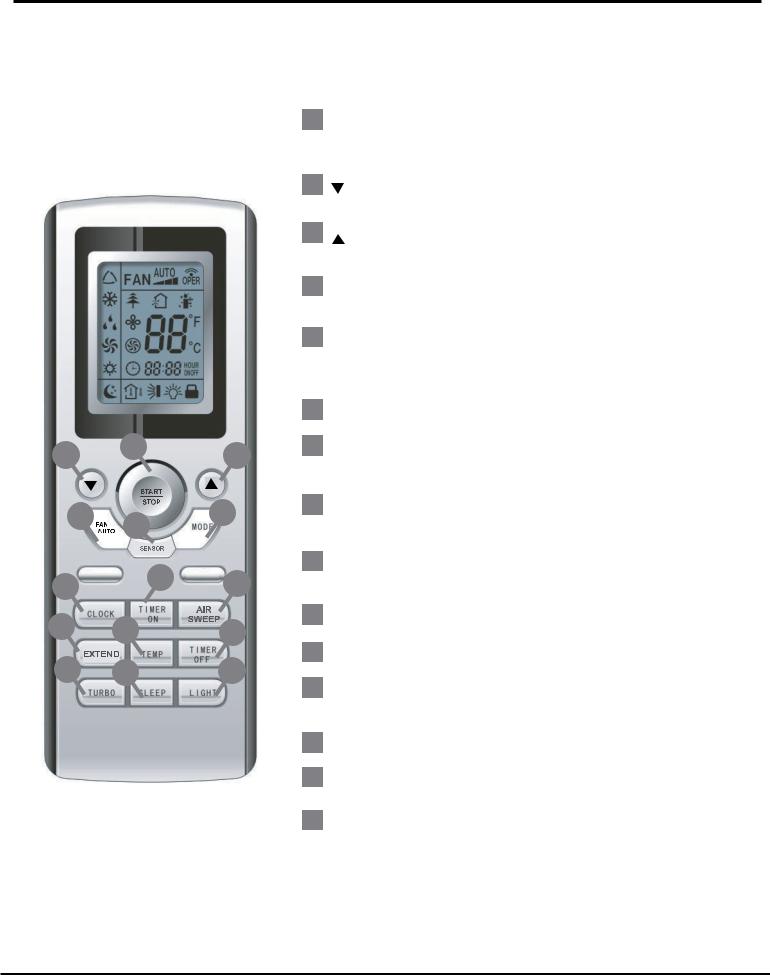
Function and Control
6. Function and Control
6.1 Remote Control Operations
1 START / STOP
P ress to start or stop operation.
ON/OFF
Press it to start or stop operation
2 : P ress to decrease temperature setting.
3
MODE
: P ress to increase temperature
Press it to select operation mode setting.
(AUTO/COOL/DRY/FAN/HEAT)
2 |
1 |
|
3 |
|
|
||
4 |
6 |
|
5 |
|
|
|
|
7 |
|
8 |
9 |
|
|
||
10 |
11 |
|
12 |
13 |
14 |
|
15 |
|
4 |
FA N AUTO |
|
||
|
|
|
|
+:Press it to increase temperature |
|
|
|
P ress to set fan speed. |
|
||
|
|
|
|
setting |
|
|
5 |
|
MODE |
|
|
|
|
|
|
-: Press it to decrease temperature |
|
|
|
P ress to select operation mode |
|||
|
|
|
|
setting |
|
|
|
|
|
(AUTO/COOL/DRY/FAN/HEAT). |
|
|
|
|
|||
|
|
|
|
FAN |
|
|
6 |
SENSOR |
|
||
|
|
|
|
Press it to set fan speed |
|
2 |
7 |
|
CLOCK |
|
|
|
|
|
|||
|
|
|
Press it set clock. |
|
|
3 |
|
|
|
Press it to set swing angle |
|
|
|
|
|
|
|
|
8 |
|
TIMER ON |
|
|
6 |
|
|
|
TIMER ON |
|
|
Press it to set auto-on timer. |
|
|||
|
|
|
|
Press it to set auto-on timer |
|
7 |
9 |
AIR |
SWEEP |
|
|
|
|
|
TIMER OFF |
|
|
|
|
|
|
|
|
|
|
Press it set swing angle. |
|
||
8 |
|
|
|
Press it to set auto-off timer |
|
10 |
|
EXTEND |
|
||
|
|
|
|
CLOCK |
|
14 |
11 |
TEMPPress it to set clock |
|
||
|
|
|
|
X-FAN (page 31)? |
|
|
12 |
TIMER OFF |
) ? |
||
|
|
Press |
it to set auto-o• timer31 |
||
|
|
|
|
TEMP (page |
|
13TURBOTURBO(page 32)?
14SLEEPSLEEP(page 32) ?
Note:Note:Onlynamedifferef nt betweenenXX-FAN-Fanand BLOW,
LIGHT
and Blow,butbutthethefunctionfunctionis theissamethe same. . 15 LIGHT
17
Press it to turn on/o• the light.
Press it to turn on/off the light.
*Remote control works with cool and Heat Pump Models
22
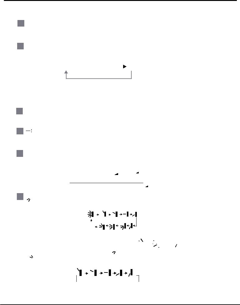
Function and Control
1ON/OFF :
Press this button to start the unit operation .Press this button again to stop the unit operation.
2 MODE :
Each time you press this button,a mode is selected in a sequence that goes from AUTO, COOL,DRY, FAN,and HEAT *, as the following:
AUTO  COOL
COOL  DRY
DRY  FAN HEAT *
*Note:Only for modelswith heating function.
After energization, AUTO mode is defaulted. In AUTO mode, the set temperature will not be displayed on the LCD, and the unit will automatically select the suitable operation mode in accordance with the room temperature to make indoor room comfortable.
3 + :
Press this button to increase set temperature.Holding down button above 2 seconds rapidly increases set temperature. In AUTO mode, set temperature is not adjustable.
4
Press this button to decrease set temperature. .Holding down button above 2 seconds rapidly decreases set temperature. In AUTO mode, set temperature is not adjustable.
5FAN:
Every press of FAN button changes the fan speed in the following order:

 Auto
Auto


 Low speed
 Medium speed
  High speed
6 
 :
:
Everypressof thebutton changes the swing anglein the follow order:
OFF
This remote controller is universal . If any command ,
, 
 or
or 
 is sent out, the unit will carry out the command as


 indicates the guide louver swings as:
23

Function and Control
7 TIMER ON:
Press TIMER ON button, "ON" blinks and  disappears. Within 5 seconds, every press of + or - button increases or decreases the ON time setting by 1 minutes. Holding down either buton above 2.5 seconds rapidly changes the time setting by 1 minute and then by 10 minutes. Within 5 seconds after setting, press TIMER ON to confirm. To cancel the TIMER ON operation, press TIMER ON button.
8TIMER OFF :
Press TIMER OFF button to set TIMER OFF. The setting method is the same as TIMER
ON.
9CLOCK :
Press CLOCK button, the icon blinks. During 5 seconds blinking, pressing + or - button adjusts preset time. Holding down either button above 2 seconds increases or decreases the time by
1 minute every 0.5 second. If you are still pressing the button after 10 minutes increased or
decreased, the time will be changed by 10 minutes every 0.5 second. During blinking, press
the CLOCK button again, the icon  will be constantly displayed and it indicates that setting has been finished.
10 X-FAN:
Pressing X-FAN button in COOL or DRY mode,the icon is displayed and the indoor
fan will continue operation for 10 minutes in order to dry the indoor unit even though you have turned off the unit.
After energization, X-FAN OFF is defaulted. X-FAN is not available in AUTO,FAN or HEAT mode.
11 TEMP: |
|
|
Press TEMP button, |
(set temperature), |
(indoor ambient temperature) and |
 (outdoor ambient temperatur) is displayed circularly. Not displaying icon is defaulted.
During operation of TEMP button, the set temperature is always displayed. Note: Outdoor ambient temperature is only displayed for some models.
24

Function and Control
12 TURBO:
Press this button in COOL or HEAT mode turns on/off Turbo function. After TURBO function is set, its icon is displayed. When switching operation mode or changing fan speed, this function will be canceled automatically.
at super high fan speed. (This function is not applicable for some models).
13SLEEP:
Press SLEEP button into SLEEP operation. Press SLEEP button again to cancel SLEEP. This function only can be used in COOL, HEAT (applicable to heat pump unit) or DRY mode, to maintain the most comfortable temperature for you.
14 LIGHT:
Press LIGHT button turns on/off the display's light. If the light is tunrned on ,  is
is
|
|
|
displayed. If the light is tunrned off |
disappears. |
|
|
|||
|
|
|
|
|
|
|
|
|
|
3 |
|
and |
4 |
About lock |
|
|
|
|
|
|
|
|
Press"+ " and "-" buttons simultaneously to lock or unlock the keypad. If the remote |
|
|||||
|
|
|
controller is locked, |
is displayed. In this case, pressing any button, |
blinks |
|
|||
|
|
|
three times. |
|
|
|
|
||
|
|
4 |
|
|
|
||||
|
2 |
and |
About switch between fahrenheit and cenrigrade |
|
|
||||
|
|
|
At unit OFF, press "MODE" and"- " buttons simultaneously to switch between |
and |
. |
||||
25
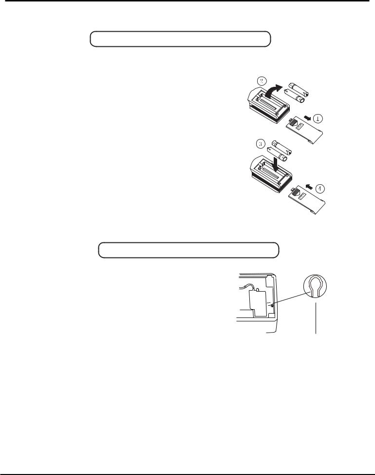
Function and Control
Replacement of Batteries
1.Remove the battery cover plate from the rear of the remote controller. (As shown in the figure)
2.Take out the old batteries.
3.Insert two new AAA1.5V dry batteries, and pay attention to the polarity. 4. Replace the battery cover plate. 
NOTES:
!When changing the batteries, do not use old or different batteries, otherwise, it may cause malfunction of the wireless remote control.
!If the wireless remote controller will not be used for a long time, please
remove batteries to prevent damage from leaking batteries.
!The operation should be performed in its receiving range.
!It should be kept 1m away from the TV set or stereo sound sets.
!If the wireless remote controller does not operate normally, please take the batteries out and replace them after 30 s. If still not operating properly, replace the batteries.
Sketch map for replacing batteries
Emergency Operation
When the wireless remote controller is lost or damaged, please use the manual switch on the main unit. Operation will be in AUTO mode and the temperature setting or fan speed can not be changed.
The manual switch can be operated as follow:
Manual switch
To operate: Pressing the AUTO/STOP button,
Fig.3
the unit enters into AUTO mode.
The microcomputer will monitor the room temperature to select the (COOL, HEAT, FAN) mode automatically,to abtain the comfortable effect.
To turn off: Press the AUTO/STOP button to switch the unit off.
26
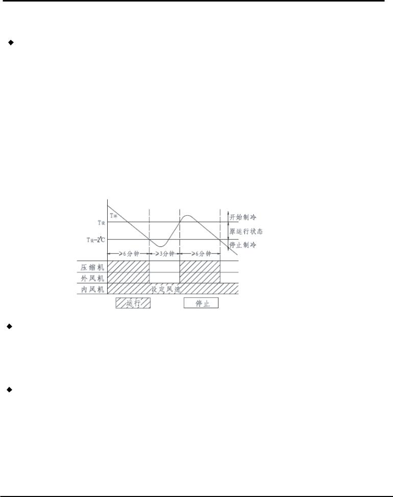
FUNCTION AND CONTROL
6.2Description of Each Control Operation
1.Temperature Parameters
Indoor preset temperature (Tpreset )
 Indoor ambient temperature (Tamb.) 2. Basic Functions
Once energized, in no case should the compressor be restarted within less than 3 minutes. In the situation that memory function is available, for the first energization, if the compressor is at stop before de-energization, the compressor will be started without a 3-minute lag; if the compressor is in operation before de-energization, the compressor will be started with a 3-minute lag; and once started, the compressor will not be stopped within 6 minutes regardless of changes in room temperature;
(1) Cooling Mode
 Working conditions and process of cooling
When Tamb.≥ Tpreset, the unit will enter cooling operation, in which case the indoor fan, the outdoor fan and the compressor will work and the indoor fan will run at preset speed.
When Tamb.≤ Tpreset-28 F, the compressor will stop, the outdoor fan will stop with a time lag of 30s, and the indoor fan will run at preset speed.
When Tpreset-28 F<Tamb.< Tpreset+34
 F, the unit will remain at its previous state.
 Under this mode, the four-way valve will be de-energized and temperature can be set within a range from 61
 F to 86
 F If the compressor is shut down for some reasonS , the indoor fan and the swing device will operate at original state.
|
|
|
|
|
|
Tamb |
|
|
|
|
|
|
Start cooling |
|
|
||
|
|
Tpreset |
|
|
|
|
|
|
|
|
|
|
|
|
|
|
|
|
|
|
|
|
|
|
|
|
|
|
|
|
|
|
|
||
|
|
|
|
|
|
|
|
|
|||||||||
|
|
|
|
|
|
|
|
|
|
|
|
|
|
|
|
|
|
|
|
|
|
|
|
|
|
|
|
|
|
|
|
|
Original working state |
|
|
|
|
|
|
|
|
|
|
|
|
|
|
|
|
|
|
|
|
|
|
|
|
|
|
|
|
|
|
|
|
|
|
||||
|
Tpreset -28 F |
|
|
|
|
|
|
|
|
|
|
|
|
|
|||
|
|
|
|
|
|
Stop cooling |
|
|
|||||||||
|
|
|
|
|
|
|
|
|
|
|
|
|
|
|
|
|
|
|
|
|
|
|
|
|
|
|
|
|
|
|
|
|
|
|
|
|
|
|
|
|
|
|
|
|
|
|
|
|
|||||
|
|
|
|
|
|
|
6 minutes |
|
3 minutes |
|
|||||||
|
|
|
|
|
|
|
|
|
6 minutes |
|
|||||||
|
|
|
|
|
|
|
|
|
|
|
|
|
|
|
|
|
|
|
|
|
|
|
|
|
|
|
|
|
|
|
|
|
|
|
|
Compressor |
|
|
|
|
|
|
|
|
|
|
|
|
|
|
|||
|
|
|
|
|
|
|
|
|
|
|
|
|
|
|
|
|
|
|
Outdoor fan |
|
|
|
|
|
|
|
|
|
|
|
|
|
|
|
|
|
|
|
|
|
|
|
|
|
|
|
|
|
|
|
|
|
|
Indoor fan |
|
|
Preset fan Speed |
|
||
|
|
|
|
|
|
|
|
|
|
|
|
|
|
|
|
Run |
|
|
|
Stop |
 Protection
Antifreeze protection
Under cooling and dry mode, 6 minutes after the compressor is started: If T evap.≤ 36 F, the compressor will operate at reduced frequency.
If T evap.≤ -30 F is detected for durative 3 minutes, the compressor will stop, and after 30 seconds, the outdoor fan will stop; and under cooling mode, the indoor fan and the swing motor will remain at the original state.
If T evap. ≥ 42 F and the compressor has remained at OFF for at least 3 minutes, the compressor will resume its original operation state.
Total current up and frequency down protection
If Itotal≤ A, frequency rise will be allowed; if Itotal ≥B, frequency rise will not be allowed; ifItotal ≥ C, the compressor will run at reduced frequency; and if Itotal ≥D, the compressor will stop and the outdoor fan will stop with a time lag of 30s.
(2) DRY Mode
 Working conditions and process of dRY
If Tamb.  Tpreset, the unit will enter cooling and dRY mode, in which case the compressor and the outdoor fan will operate and the indoor fan will run at low speed.
If Tpreset-28 F
F  Tamb.≤ Tpreset, the compressor remains at its original operation state.
If Tamb.< Tpreset -28 F , the compressor will stop, the outdoor fan will stop with a time lag of 30s, and the indoor fan will operate at low speed.
27
 Loading...