

Español
Français
English
KEEP THIS OPERATION MANUAL
FOR FUTURE REFERENCE
P/N9309278028-02
OPERATING MANUAL
MODE D’EMPLOI
MANUAL DE FUNCIONAMIENTO
COOLING MODEL
ROOM AIR CONDITIONER
WALL MOUNTED TYPE
Indoor Unit
MW09C1E
MW12C1E
Outdoor Unit
MR09C1E
MR12C1E
Friedrich Air Conditioning Co.
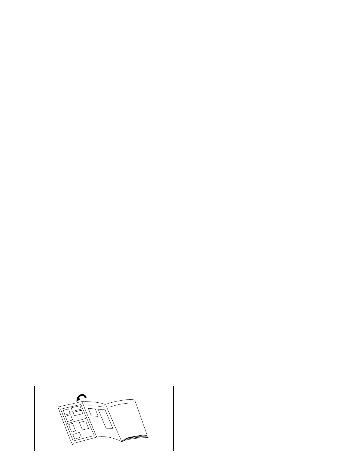
÷ Refer to the fold-out page on the cover.
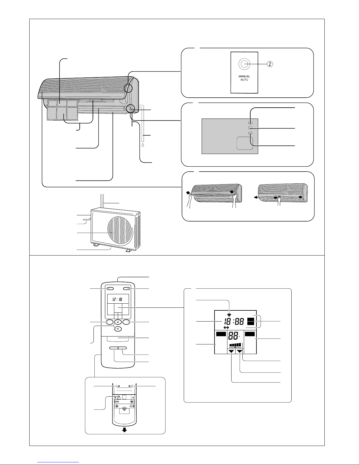
Fig. 6
Fig. 8
Fig. 7
OPERATION
SWING
TIMER
7
6
5
1
4
8
Fig. 5
Fig. 1
Fig. 2
Fig. 3
Fig. 4
^
$
#
@
%
0
-
9
!
=
~
3
SLEEP TIMER
MASTER
CONTROL
SET
TEMP.
SET
TIME
FAN
CONTROL
START/STOP
SWING
LOUVER
CLOCK
CLOCK TIMER RESET
AM
PM
PM
OFF
ON
HM
COOL
DRY
FAN
AUTO
HIGH
MED
LOW
QUIET
AUTO
F
SLEEP
ON
OFF
LOW HIGH
ACL
OPEN
&
*
(
)
_
+
£
¡
¢
∞
§
•
º
ª–
Ÿ
⁄
¤
≠
¶
AIR FLOW
DIRECTION
™

En-1
CONTENTS
SAFETY PRECAUTIONS .................................... En-1
FEATURES AND FUNCTIONS ........................... En-4
NAME OF PARTS ............................................... En-5
PREPARATION.................................................... En-6
OPERATION ........................................................ En-7
TIMER OPERATION............................................ En-9
SLEEP TIMER OPERATION.............................. En-10
ADJUSTING THE DIRECTION OF
AIR CIRCULATION ........................................... En-11
SWING OPERATION ........................................ En-12
MANUAL AUTO OPERATION ......................... En-12
CLEANING AND CARE..................................... En-13
TROUBLESHOOTING ....................................... En-16
OPERATING TIPS ............................................. En-17
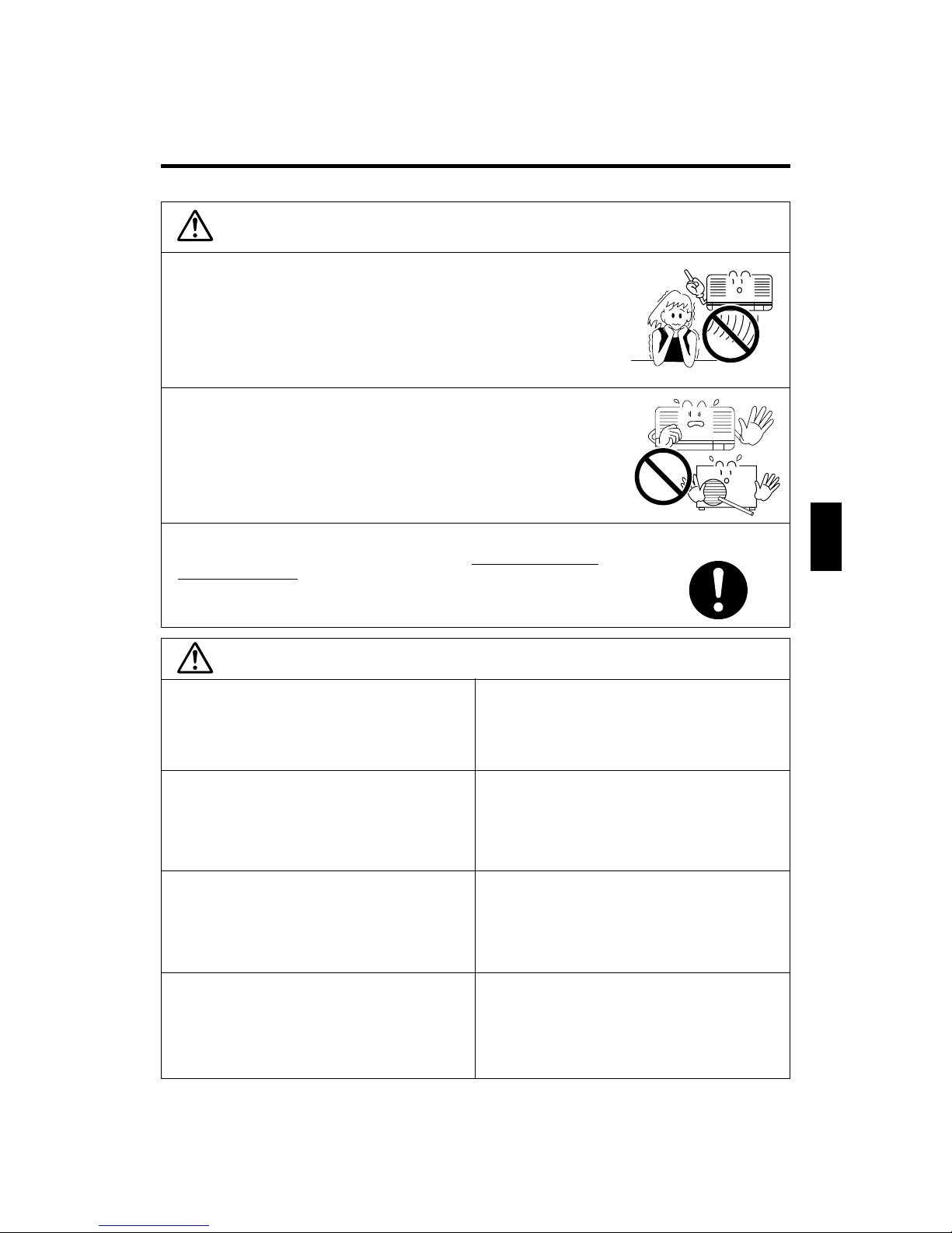
SAFETY PRECAUTIONS
WARNING
This mark indicates procedures which, if improperly performed, might possibly result in personal harm to the user, or damage to property.
CAUTION
¶ Before using the appliance, read these “SAFETY PRECAUTIONS” thoroughly and operate in the correct way.
¶ The instructions in this section all relate to safety; be sure to maintain save operating conditions.
¶ “CAUTION” and “WARNING” have the following meanings in these instructions:
WARNING
Do not attempt to install this air conditioner by yourself.
¶ Consult authorized service personnel for all installations.
Consult authorized service personnel for any repairs.
¶ Do not attempt to remove parts, or service the unit yourself, since you may be
exposed to dangerous electrical shock. This appliance contains no user-serviceable
parts.
When moving, consult authorized service personnel for
disconnection and installation of the unit.
This mark indicates procedures which, if improperly performed, might lead to the death or
serious injury of the user.
Safety Symbols
% The triangular symbol indicates WARNING, CAUTION and DANGER items.
This symbol indicates prohibited operations. The prohibited action is indicated both within the symbol,
and in nearby explanations.
¶ This symbol indicates instructions regarding operations which are to be performed by the user.
En-2
Do not stay in direct cooling airflow for long periods.
¶ Excessive direct exposure to chilled air could be bad for your health.
¶ Be especially careful when going to bed, and in rooms where infants, aged, or sick
people are staying.
Do not insert fingers or objects into the outlet port or intake grilles.
¶ A fan operates at high speed inside the unit, and personal injury could result.
¶ Be particularly careful regarding small children.
WARNING
PRECAUTIONS
In the event of a malfunction (burning smell, etc.), immediately
stop operation, disconnect the power, and consult authorized
service personnel.
¶ Continuing to operate the unit under such conditions could lead to hazard of fire or
electrical shock.
Do not climb on, or place objects on, the
air conditioner.
¶ Personal injury could result from a falling object, or if
the unit tips over.
Do not set flower vases or water containers on top of air conditioners.
¶ Water leaking inside the unit could damage electrical
insulation, leading to danger of electrical shock.
Do not direct air flow at fireplaces or heating apparatuses.
¶ Direct air blowing on fires could result in improper
combustion or fire.
Do not place animals or plants in the direct
path of the air flow.
Do not hang on or cover the air conditioner.
Be careful to provide adequate ventilation
particularly when using the unit in combination with other heating apparatus.
¶ Insufficient ventilation could lead to oxygen starva-
tion.
Do not expose the air conditioner directly
to water.
¶ Electrical insulation could be damaged, resulting in
electrical shock.
Do not operate the air conditioner with
wet hands.
¶ Electrical shock could result.
CAUTION
En-3
PRECAUTIONS
CAUTION
Check the condition of the installation for
damage.
¶ After lengthy use, arrange for visit by authorized ser-
vice personnel to check installation condition.
Always turn off power whenever cleaning
the air conditioner or changing the air filter.
¶ A fan operates at high speed inside the unit, and per-
sonal injury could result.
Turn off power source when not using the
unit for extended periods.
Take precautions to prevent infants from
accidentally swallowing batteries.
Do not drink the water drained from the
air conditioner.
Do not use in applications involving the
storage of foods, plants or animals,
precision equipment, or art works.
¶ The quality of the stored items may deteriorate.
Take out the batteries from the remote
control unit when not using for a long
time.
¶ Take out the batteries to prevent troubles caused by
battery liquid leakage.
¶ If leaking battery fluid comes in contact with your
skin, eyes, or mouth, immediately wash with copious
amounts of water, and consult your physician.
Install the indoor unit and remote control
unit at least one meter from any television
sets or radio.
¶ Signal radiation could be induced into the system to
give erroneous operation.
Always operate with the air filter installed.
¶ Operating the unit without the air filter could cause
excessive dirt to collect on internal parts, leading to
malfunction.
When installing the indoor unit and
outdoor unit, take precautions to prevent
access by infants.
¶ Unexpected accidents could occur.
Do not use inflammable gases near the air
conditioner.
Avoid installing the air conditioner near a
fireplace or other heating apparatus.
¶ Exposure to excessive heat could result in deforma-
tion of the outer case.
Do not block or cover the intake grille and
outlet port.
¶ Obstructing the ports will reduce operating efficiency,
leading to improper operation and possible damage.
Do not touch the heat exchanger radiator
fins.
¶ Personal injury could result.
¶ Be particularly careful when cleaning.
¶ Bending or damage to the fins will affect the effi-
ciency of the unit.
Be sure to attach the intake grille securely.
En-4
FEATURES AND FUNCTIONS
AUTOMATIC OPERATION
Merely press the START/STOP button, and the unit will begin automatic operation in either the Heating, Cooling, Dry,
or Monitor modes as appropriate, in accordance with the
thermostat setting and the actual temperature of the room.
SLEEP TIMER
When the SLEEP timer button is pressed during cooling
mode, the thermostat setting is gradually raised during the
period of operation. When the set time is reached, the unit
automatically turns off.
WIRELESS REMOTE CONTROL UNIT
The WIRELESS REMOTE CONTROL UNIT allows convenient
control of air conditioner operation.
SWING OPERATION
The Air Flow Direction Louvers swings automatically up
and down so that the air speeds to every nook and corner
of your room.
REMOVABLE INTAKE GRILLE
The indoor unit's INTAKE GRILLE can be removed for easy
cleaning and maintenance.
MILDEW-RESISTANT FILTER
The AIR FILTER has been treated to resist mildew growth,
thus allowing cleaner use and easier care.
SUPER QUIET OPERATION
When the FAN CONTROL button is used to select QUIET,
the unit begins super-quiet operation; the indoor unit's
airflow is reduced for quieter operation.

En-5
NAME OF PARTS
Fig. 6 Remote Control Unit
& SLEEP button
* MASTER CONTROL button
( SET TEMP. /SET TIME button ( / )
) Signal Transmitter
_ TIMER button
+ FAN CONTROL button
¡ START / STOP button
™ AIR FLOW DIRECTION button
£ SWING LOUVER button
Rear side (Fig. 7)
¢ TIME ADJUST button
∞ ACL button
(located inside battery compartment)
§ TEST RUN button
÷ This button is used when installing the unit,
and should not be used under normal
conditions, as it will cause the air
conditioner's thermostat function to operate
incorrectly.
÷ If this button is pressed during normal
operation, the unit will switch to test
operation mode, and the Indoor Unit's
OPERATION Indicator Lamp and TIMER
Indicator Lamp will begin to flash
simultaneously.
÷ To stop the test operation mode, press the
START/STOP button to stop the air
conditioner.
¶ Remote Control Unit Display (Fig. 8)
• Transmit Indicator
ª Clock Display
º Operating Mode Display
– Timer Mode Display
≠ Fan Speed Display
Ÿ Temperature Set Display
⁄ Timer Set Indicator
¤ Temperature Set Indicator
Fig. 1 Indoor Unit
1 Operating Control Panel (Fig. 2)
2 MANUAL AUTO button
3 Remote Control Signal Receiver
4 Indicator Lamps (Fig. 3)
5 OPERATION Indicator Lamp (red)
6 TIMER Indicator Lamp (green)
÷ If the TIMER Indicator Lamp flashes when
the timer is operating, it indicates that a fault
has occurred with the timer setting (See
Page 17 Auto Restart).
7 SWING Indicator Lamp (orange)
8 Intake Grille (Fig. 4)
9 Air Filter
0 Air Flow Direction Louver
- Right-Left Louvers
(behind Air Flow Direction Louver)
= Drain Hose
~ Inter Unit-Line
! Air Cleaning Filter (optional)
Fig. 5 Outdoor Unit
@ Power Supply
# Intake Port
$ Outlet Port
% Pipe Unit
^ Drain port (bottom)

En-6
Turn on the Power
In the case of a direct line connection, turn on the circuit
breaker.
Load Batteries (AAA x 2)
Press and slide the battery compartment lid on the reverse
side to open it.
Slide in the direction of the arrow while pressing the mark.
Insert batteries.
Be sure to align the battery polarities (ª/·) correctly.
Close the battery compartment lid.
Set the Current Time
Press the TIME ADJUST button (Fig. 7 ¢).
Use the tip of a ball-point pen or other small object to press the button.
Use the / SET TEMP. SET TIME buttons (Fig. 6 ()
to adjust the clock to the current time.
button: Press to advance the time.
button: Press to reverse the time.
(Each time the buttons are pressed, the time will be advanced/reversed
in one-minute steps; hold the buttons depressed to change the time quickly
in ten-minute steps).
Press the TIME ADJUST button again.
This completes the time setting and starts the clock.
To Use the Remote Control Unit
÷ The Remote Control Unit must be pointed at signal receiver (Fig. 1 3) to operate
correctly.
÷ Operating Range: About 7 meters.
÷ When a signal is properly received by the air conditioner, a beep be heard.
÷ If no beep is heard, press the Remote Control Unit button again.
Remote Control Unit Holder
1
2
3
PREPARATION
CAUTION!
÷ Take care to prevent infants from
accidentally swallowing batteries.
÷ When not using the remote control unit for
an extended period, remove the batteries
to avoid possible leakage and damage to
the unit.
÷
If leaking battery fluid comes in contact with
your skin, eyes, or mouth, immediately
wash with copious amounts of water, and
consult your physician.
÷ Dead batteries should be removed quickly
and disposed of properly, either by placing
in a public battery collection receptacle, or
by returning to appropriate authority.
÷ Do not attempt to recharge dry batteries.
Never mix new and used batteries, or
batteries of different types.
Batteries should last about one year under
normal use. If the remote control unit’s
operating range becomes appreciably
reduced, replace the batteries and press
the ACL button (Fig. 7 ∞) with the tip of a
ballpoint pen or other small object.
1
3
2
Screws
Insert
Press in
Slide up
Pull out
2 Set the Remote Control
Unit.
3 To remove the Remote
Control Unit.
1 Mount the Holder.
ON

En-7
SLEEP TIMER
MASTER
CONTROL
SET
TEMP.
SET
TIME
FAN
CONTROL
START/STOP
COOL
SLEEP TIMER
MASTER
CONTROL
SET
TEMP.
SET
TIME
FAN
CONTROL
AUTO
SLEEP TIMER
MASTER
CONTROL
SET
TEMP.
SET
TIME
FAN
CONTROL
START/STOP
F
OPERATION
To Select Mode Operation
Press the START/STOP button (Fig. 6 ¡).
The Indoor Unit’s OPERATION Indicator Lamp (red) (Fig.3 5) will light.
The air conditioner will start operation.
Press the MASTER CONTROL button (Fig.6 *) to select
the desired mode.
Each time the button is pressed, the mode will change in the following order.
1
Example: When set to COOL
About three seconds later, the entire display will reappear.
Example: When set to 80°F.
Example: When set to AUTO.
The thermostat setting should be considered a standard value, and may differ
somewhat from the actual room temperature.
AUTO COOL
DRY
FAN
In order to increase the drying effect
during quiet cooling operation, the fan
of the indoor unit may stop.
To Set the Thermostat
Press the TEMPERATURE set button.
button: Press to increase the thermostat setting.
button: Press to lower the thermostat setting.
¶ Thermostat setting range:
Cooling/Drying ..................................................... 64°F to 88°F
Fan......................................................................... 62°F to 88°F
About three seconds later, the entire display will reappear.
NOTE:
¶ The thermostat setting should be considered a standard value, and may differ
somewhat from the actual room temperature.
¶ During Fan mode, set the unit to “– –” for continuous fan operation regardless
of room temperature.
To Set the Fan Speed
Press the FAN CONTROL button (Fig. 6 +).
Each time the button is pressed, the fan speed changes in the following order:
About three seconds later, the entire display will reappear.
When set to AUTO:
Cooling: As the room temperature approaches that of the thermostat setting, the
fan speed becomes slower.
Fan: The fan will operate at the optimum speed in accordance with the room
temperature in the vicinity of the indoor unit.
When set to QUIET:
SUPER QUIET operation begins. The indoor unit's airflow will be reduced for quieter operation.
¶ SUPER QUIET operation cannot be used during Dry mode. (The same is true
when dry mode is selected during AUTO mode operation.)
¶ Cooling performance will be reduced somewhat during SUPER QUIET opera-
tion.
AUTO
LOW
MED
HIGH
3
333
3
QUIET
2

En-8
MASTER
CONTROL
SET
TEMP.
SET
TIME
FAN
CONTROL
LOW HIGH
MASTER
CONTROL
SET
TEMP.
SET
TIME
FAN
CONTROL
AUTO
OPERATION
Press the MASTER CONTROL button to select AUTO.
The operating mode “AUTO” will appear alone in the display. The transmit indicator will flash to indicate the command has been sent, and about three seconds
later the entire display panel will reappear.
To Set the Thermostat
Press the TEMPERATURE set button.
About three seconds later, the entire display will reappear.
NOTE: The thermostat setting should be considered a standard value, and may
differ somewhat from the actual room temperature.
When set to
4°F lower
When set to
2°F lower
When set to
“normal”
When set to
2°F higher
When set to
4°F higher
LOW HIGH LOW HIGH LOW HIGH LOW HIGH LOW HIGH
Example: When set to “normal”.
To Select Automatic Operation
To Stop Operation
Press the START/STOP button.
The OPERATION indicator lamp (red) (Fig. 3 5) will go out.
About Mode Operation
During Cooling/Dry mode:
Set the thermostat to a temperature setting that is lower than the current room
temperature. The Cooling and Dry
modes will not operate if the thermostat
is set higher than the actual room temperature (in Cooling mode, the fan alone
will operate).
During Fan mode:
¶ Fan operation begins when room tem-
perature in the vicinity of the air conditioner rises above the set thermostat
temperature; when the temperature
drops, fan operation stops.
¶ If the air emitted feels too cool, raise
the thermostat setting.
AUTO: ¶ Depending on the room temperature at the time operation begins,
the operating mode will be switched automatically as shown in the
accompanying table.
Also, depending on the operating mode, the room temperature setting will cause the “standard” temperature to be set as shown.
Actual Room Operating Mode Thermostat Setting
Temperature (standard setting)
88°F or above = Cooling = 82°F
82°F to 88°F = Cooling = 80°F
78°F to 82°F = Dry = 76°F
74°F to 78°F = Dry = 72°F
Below 74°F = Dry = 68°F
The operating mode and standard thermostat settings are selected automatically when operation begins.
¶ When automatic operation is initiated, the fan will run at very low
speed for about one minute while the unit detects and selects the
proper operating mode.
¶ Once the operating mode has been set, the mode will not change
even if the room temperature changes.
¶ If the START/STOP button is pressed to recommence operation within
two hours after stopping automatic operation, the unit will begin operating from the same mode as before.
Cooling: ¶ Use to cool your room.
Dry: ¶ Use for gently cooling while dehumidifying your room.
¶ You cannot heat the room during Dry mode.
¶ During Dry mode, the unit will operate at low speed; in order to ad-
just room humidity, the indoor unit’s fan may stop from time to time.
Also, the fan may operate at very low speed when detecting room
humidity.
¶ The fan speed cannot be changed manually when Dry mode has been
selected.
Fan: ¶ Use to circulate warm air from ceiling area throughout room when
using space heaters.

En-9
To Cancel the Timer
Use the TIMER button to select “TIMER
RESET.”
The air conditioner will return to normal
operation.
To Change the Timer Setting
1. Follow the instructions given in the
section “To Use the ON Timer or OFF
Timer” to select the timer setting you
wish to change.
2. Press the TIMER button to select either
OFF = ON or OFF + ON.
To Stop Air Conditioner Operation while
the Timer is Operating
Press the START/STOP button.
To Change Operating Conditions
If you wish to change operating conditions
(Mode, Fan Speed, Thermostat Setting),
after making the timer setting wait until the
entire display reappears, then press the
appropriate buttons to change the
operating condition desired.
To Cancel the Timer
Use the TIMER button to select “TIMER
RESET.”
The air conditioner will return to normal
operation.
To Change the Timer Setting
Perform steps 2 and 3.
To Stop Air Conditioner Operation while
the Timer is Operating
Press the START/STOP button.
To Change Operating Conditions
If you wish to change operating conditions
(Mode, Fan Speed, Thermostat Setting),
after making the timer setting wait until the
entire display reappears, then press the
appropriate buttons to change the
operating condition desired.
To Use the ON timer or OFF timer
Press the START/STOP button (Fig. 6 ¡).
(if the unit is already operating, proceed to step 2).
The indoor unit’s OPERATION Indicator Lamp (red) (Fig. 3 5) will light.
Press the TIMER button (Fig. 6 _) to select the OFF timer
or ON timer operation.
Each time the button is pressed the timer function changes in the following
order:
TIMER OPERATION
Before using the timer function, be sure that the Remote Control Unit is set to the correct current time (See Page 6).
1
3
RESET OFF ON
PROGRAM (OFF ON, OFF ON)
The indoor unit’s TIMER Indicator lamp (green) (Fig. 3 6) will light.
Use the SET TEMP.SET TIME button (Fig. 6 () to adjust
the desired OFF time or ON time.
Set the time while the time display is flashing (the flashing will continue for
about five seconds).
button: Press to advance the time.
button: Press to reverse the time.
About five seconds later, the entire display will reappear.
2
To Use the Program timer
Press the START/STOP button(Fig. 6 ¡).
(if the unit is already operating, proceed to step 2).
The indoor unit’s OPERATION Indicator Lamp (red) (Fig. 3 5) will light.
Set the desired times for OFF timer and ON timer.
See the section “To Use the ON Timer or OFF Timer” to set the desired mode
and times.
About three seconds later, the entire display will reappear.
The indoor unit’s TIMER Indicator Lamp (green) (Fig. 3 6) will light.
Press the TIMER button (Fig. 6 _) to select the PROGRAM
timer operation (either OFF = ON or OFF + ON will
display).
The display will alternately show “OFF timer” and “ON timer”, then change
to show the time setting for the operation to occur first.
÷ The PROGRAM timer will begin operation. (If the ON timer has been
selected to operate first, the unit will stop operating at this point).
About five seconds later, the entire display will reappear.
1
2
About the Program timer
÷ The PROGRAM timer allows you to integrate OFF timer and ON timer operations
in a single sequence. The sequence can involve one transition from OFF timer to
ON timer, or from ON timer to OFF timer, within a twenty-four hour period.
÷ The first timer function to operate will be the one set nearest to the current time.
The order of operation is indicated by the arrow in the Remote Control Unit’s
display (OFF = ON, or OFF + ON).
÷ One example of Program timer use might be to have the air conditioner
automatically stop (OFF timer) after you go to sleep, then start (ON timer)
automatically in the morning before you arise.
3

En-10
SLEEP TIMER OPERATION
Unlike other timer functions, the SLEEP timer is used to set the length of time until air conditioner operation is stopped.
To Use the SLEEP Timer
While the air conditioner is operating or stopped, press the
SLEEP button (Fig. 6 &).
The indoor unit’s OPERATION Indicator Lamp (red) (Fig 3. 5) lights and the TIMER
Indicator Lamp (green) (Fig 3. 6) light.
To Change the Timer Setting
Press the SLEEP button (Fig 6. &) once again and set the time
using the SET TIME buttons (Fig 6. ().
Set the time while the Timer Mode Display is flashing (the flashing will continue
about five seconds).
button: Press to advance the time.
button: Press to reverse the time.
About five seconds later, the entire display will reappear.
To Cancel the Timer:
Use the TIMER button to select “TIMER
RESET”.
The air conditioner will return to normal
operation.
To Stop the Air Conditioner During
Timer Operation:
Press the START/STOP button.
To prevent excessive cooling during sleep, the SLEEP timer function automatically modifies the thermostat setting in accordance with the time setting. When the set time has elapsed, the air conditioner completely stops.
About the SLEEP timer
During Cooling/Dry operation:
When the SLEEP timer is set, the thermostat setting is automatically raised 2°F every sixty minutes. When the thermostat has been raised a total of 4°F, the thermostat setting at
that time is maintained until the set time has elapsed, at
which time the air conditioner automatically turns off.
2°F
4°F
Set time
1 hour
SLEEP timer setting

En-11
CAUTION
÷ Never place fingers or foreign objects
inside the outlet ports, since the internal
fan operates at high speed and could
cause personal injury.
ADJUSTING THE DIRECTION OF AIR CIRCULATION
Vertical (up-down) direction of airflow is adjusted by pressing the Remote Control Unit's AIR FLOW DIRECTION button.
Horizontal (right-left) airflow direction is adjusted manually, by moving the Air Flow Direction Louvers.
Whenever making horizontal airflow adjustments, start air conditioner operation and be sure that the vertical air direction
louvers are stopped.
Vertical Air Direction Adjustment
Press the AIR FLOW DIRECTION button (Fig. 6 ™).
Each time the button is pressed, the air direction range will change as follows:
÷ Use the air direction adjustments within the ranges shown above.
÷ The vertical airflow direction is set automatically as shown, in accordance with
the type of operation selected.
During Cooling/Dry mode: Horizontal flow 1
During Fan mode: Downward flow 6
¶ During AUTO mode operation, for the first minute after beginning operation,
airflow will be horizontal 1; the air direction cannot be adjusted during this
period.
Right-Left Louvers
Knob
1
2
3
4
5
67
Cooling/
Dry mode
Fan mode
3 (6)
NOTE
12
1 732 5 46
¶ Always use the remote control unit's
AIR FLOW DIRECTION button to adjust
the vertical airflow louvers. Attempting to move them manually could result in improper operation; in this case,
stop operation and restart. The louvers
should begin to operate properly
again.
¶ When used in a room with infants, chil-
dren, elderly or sick persons, the air
direction and room temperature
should be considered carefully when
making settings.
Right-Left Adjustment
Adjust the Right-Left Louvers
÷ Move the Right-Left Louvers to adjust air flow in the direction you prefer.
NOTE
You can select the air direction 1, 2 , 3 , or 6 (downward) by pressing the AIR
FLOW DIRECTION button.
Use the air direction 6 when you want to cool yourself for a while after taking
a bath or shower, or after coming back home in summer months.
But, for prevention of condensation on the louver, the air direction 6 is automatically released after 30 minutes and turned to the air direction 3.

En-12
To Select SWING Operation
Press the SWING LOUVER button (Fig.6 £ ).
The SWING Indicator Lamp (orange) (Fig. 3 7) will light.
In this mode, the Air Flow Direction Louvers will swing automatically to direct the
airflow both up and down.
To Stop SWING Operation
Press the SWING LOUVER button (Fig.6 £ ) once again.
The SWING Indicator Lamp (orange) (Fig. 3 7) will go out.
Airflow direction will return to the setting before swing was begun.
SWING OPERATION
Begin air conditioner operation before performing this procedure.
MANUAL AUTO OPERATION
Use the MANUAL AUTO operation in the event the Remote Control Unit is lost or otherwise unavailable.
How To Use the Main Unit Controls
Press the MANUAL AUTO button (Fig. 2 2) on the main unit
control panel.
To stop operation, press the MANUAL AUTO button once again.
(Controls are located inside the Intake Grille)
¶ When the air conditioner is operated
with the controls on the Main Unit, it
will operate under the same mode as
the AUTO mode selected on the Remote Control Unit (see page 8).
¶ The fan speed selected will be “AUTO”
and the thermostat setting will be standard.
1
2
3
4
5
67
Cooling/
Dry mode
Fan mode
(4 7)
NOTE
13
,
4 713
,
÷ The SWING operation may stop temporarily when the
air conditioner's fan is not operating or when operating
at very low speeds.
÷ The airflow direction can not be adjusted during SWING
operation even when the AIR FLOW DIRECTION button
is pressed.
The air swings between 4 and 7 by pressing the
SWING LOUVER button after selecting the air direction
6 (downward) by pressing the AIR FLOW DIRECTION
button.
Use this operation when you want to cool yourself for
a while after taking a bath or shower, or after coming
back home in summer months.
But, for prevention of condensation on the louver, the
swing of the air direction 4Ô 7 is automatically
released after 30 minutes and turned to the swing of
the air direction 1Ô3.
÷ The SWING range is as follows:
About Swing Operation
NOTE

En-13
CLEANING AND CARE
WARNING
Before cleaning the unit, be sure to stop the unit and disconnect the power.
1. Disconnect the power. 2. Turn off the electrical breaker.
¶ A fan operates at high speed inside the unit, and personal injury could result.
When cleaning the air conditioner, turn off the electrical
breaker.
The unit can be damaged by gasoline, benzine, thinners,
insecticides and other chemical agents.
Do not use inflammable sprays such as lacquer or hair
spray near the air conditioner.
Thinner
Gasoline
Benzine
Cleansing rag
Hair spray
Lacquer
Never use water that is hotter than 100°F. The body may
warp or change color.
More than
100°F
ON
OFF
ON
Cleaning the Indoor Unit
Clean the indoor unit by wiping with a cloth dipped in
cool or warm water, then wipe with another soft, clean,
dry cloth.
When Not Using the Unit for Extended
Periods (One Month or More)
Operate the unit on fan mode for about one-half day on a
day with clear weather, to assure that the internal parts
are dry (see page 7).
CAUTION
When not using the unit for extended periods, disconnect the power for safety.
Inspections and Repairs
Depending on the conditions of use, the internal parts of an air conditioner will become dirty after about two or three
seasons of use, and performance may be affected. For this reason, regular professional maintenance is recommended.
Consult authorized service personnel.

En-14
Cleaning the Intake Grille
1. Open the Intake Grille.
1 Place your fingers at both lower ends of the grille
panel, and lift forward; if the grille seems to catch
partway through its movement, continue lifting upward to remove.
2 Pull past the intermediate catch and open the Intake
Grille wide so that it becomes horizontal.
4. Set the mounting shaft of the Intake Grille
into the bearings at the top of the panel.
1 Pull the Knobs all the way.
2 Hold the grille horizontal and set the left and right
mounting shafts into the bearings at the top of the
panel.
1
1
2
2
Intake Grille
2
1
Intake
Grille
Mounting
shaft
Bearing
Knob
Intake Grille
3. Clean with water.
Remove dust with a vacuum cleaner: wipe the unit with
warm water, then dry with a clean, soft cloth.
Raise the horizontal Intake Grille to remove it.
Intake Grille
Mounting shaft
Knob
2. Unlock the Intake Grille.
Hold the Intake Grille with one hand and pull the Knobs
on the right and the left all the way to unlock the Intake
Grille.
6. Close the Intake Grille.
Push the lower edge of the Intake Grille at both ends
and at the center to close it.
Intake Grille
Mounting shaft
Knob
5. Lock the Intake Grille.
Hold the Intake Grille with one hand and push the Knobs
on the right and the left all the way in to lock the Intake
Grille mounting shafts.
CAUTION
Do not operate with open Intake Grille, as this can
cause accidents.

En-15
Cleaning the Air Filter
1. Open the Intake Grille, and remove the Air
Filter.
Lift up the air filter's handle, disconnect the two lower
tabs and pull out.
2. Remove dust with a vacuum cleaner or
by washing.
After washing, allow to dry thoroughly in a shaded
place.
3. Replace the Air Filter and close the Intake
Grille.
1 Align the sides of the Air Filter with the panel, and
push in fully, making sure the two lower tabs are
returned properly to their holes in the panel.
2 Close the Intake Grille.
(For purposes of example, the illustration shows the
unit without Intake Grille installed.)
÷ Dust can be cleaned from the Air Filter either with a
vacuum cleaner, or by washing the filter in a solution of
mild detergent and warm water. If you wash the filter,
be sure to allow it to dry thoroughly in a shady place
before reinstalling.
÷ If dirt is allowed to accumulate on the Air Filter, air flow
will be reduced, lowering operating efficiency and
increasing noise.
÷ During periods of normal use, the Air Filters should be
cleaned every two weeks.
Air filter handle
Hooks (two places)
Hooks (two places)
CLEANING AND CARE
When using the optional Air Cleaning Filter
÷ Install the optional Air Cleaning Filter set (UTR-FA03) as instructed (Instruction Manual are furnished with the Air Cleaning
Filter set).
÷ When used for extended periods, the unit may accumulate dirt inside, reducing its performance. We recommend that
the unit be inspected regularly, in addition to your own cleaning and care. For more information, consult authorized
service personnel.
÷ When cleaning the unit's body, do not use water hotter than 40°C, harsh abrasive cleansers, or volatile agents like
benzene or thinner.
÷ Do not expose the unit body to liquid insecticides or hairsprays.
÷ When shutting down the unit for one month or more, first allow the fan mode to operate continuously for about
onehalf day to allow internal parts to dry thoroughly.

En-16
÷ If the unit is stopped and then immediately started again, the
compressor will not operate for about 3 minutes, in order to
prevent fuse blowouts.
÷ Whenever the Power is disconnected and then reconnected to
a power outlet, the protection circuit will operate for about 3
minutes, preventing unit operation during that period.
÷ During operation and immediately after stopping the unit, the
sound of water flowing in the air conditioner’s piping may be
heard. Also, noise may be particularly noticeable for about 2
to 3 minutes after starting operation (sound of coolant flowing).
÷ During operation, a slight squeaking sound may be heard. This
is the result of minute expansion and contraction of the front
cover due to temperature changes.
÷ Some smell may be emitted from the indoor unit. This smell is
the result of room smells (furniture, tobacco, etc.) which have
been taken into the air conditioner.
÷ During Cooling or Dry operation, a thin mist may be seen
emitted from the indoor unit. This results from the sudden
Cooling of room air by the air emitted from the air conditioner,
resulting in condensation and misting.
÷ The fan may operate at very low speed during Dry operation
or when the unit is monitoring the room’s temperature.
÷ During SUPER QUIET operation, the fan will operate at very
low speed.
÷ In the monitor AUTO operation, the fan will operate at very
low speed.
TROUBLE SHOOTING
WARNING!
In the event of a malfunction (burning smell, etc.), immediately stop operation, disconnect
the Power and consult authorized service personnel.
Merely turning off the unit’s power switch will not completely disconnect the unit from the
power source. Always be sure to disconnect the Power or turn off your circuit breaker to
ensure that power is completely off.
Before requesting service, perform the following checks:
NORMAL
FUNCTIONS
Doesn’t operate immediately:
Noise is heard:
Smells:
Mist or steam are emitted:
Airflow is weak or stops:
Problem
See Page
––––
––––
––––
––––
7
7
7
Symptom

En-17
Items to Check
÷ Has there been a power failure?
÷ Has a fuse blown out, or a circuit breaker been tripped?
÷ Is the POWER switch set to the OFF position?
÷ Is the timer operating?
÷ Is the air filter dirty?
÷ Are the air conditioner’s intake grille or outlet port blocked?
÷ Did you adjust the room temperature settings (thermostat)
correctly?
÷ Is there a window or door open?
÷ Is a window allowing bright sunlight to enter? (Close the curtains.)
÷ Are there heating apparatus and computers inside the room, or
are there too many people in the room?
÷ Is the unit set for SUPER QUIET operation?
÷ Are the Remote Control Unit's batteries dead?
÷ Are the Remote Control Unit's batteries loaded properly?
See Page
––––
6
9 - 10
––––
7
6
Symptom
Doesn’t operate at all:
Poor Cooling performance:
The unit operates
differently from the
remote control unit's
setting:
CHECK ONCE
MORE
If the problem persists after performing these checks, or if you notice burning smells, or the
TIMER Indicator Lamp (Fig. 3, 6) flashes, immediately stop operation, disconnect the Power
and consult authorized service personnel.
TROUBLE SHOOTING
OPERATING TIPS
WARNING!
In Event of Power Interruption
Auto Restart
÷ The air conditioner power has been interrupted by a
power failure. The air conditioner will then restart
automatically in its previous mode when the power is
restored.
÷ Operated by settings before the power failure. Then, the
Air Flow Direction Louvers will automatically change to
their standard direction.
÷ If a power failure occurs during TIMER operation, the
timer will be reset and the unit will begin (or stop)
operation at the new time setting. In the event that this
kind of timer fault occurs, the TIMER Indicator Lamp
(green) will flash (see page 5).
÷ Use of other electrical appliances (electric shaver, etc.)
or nearby use of a wireless radio transmitter may cause
the air conditioner to malfunction. In this event,
temporarily disconnect the Power, reconnect it, and then
use the Remote Control Unit to resume operation.
Operation and Performance

En-18
OPERATING TIPS
Temperature and Humidity Range
DB : Dry Bulb Temperature
WB : Wet Bulb Temperature
÷ If the air conditioner is used under higher temperature conditioner than those listed, the built-in protection circuit may
operate to prevent internal circuit damage. Also, during Cooling and Dry modes, if the unit is used under conditions of
lower temperature than those listed above, the heat-exchanger may freeze, leading to water leakage and other damage.
÷ Do not use this unit for any purposes other than the Cooling, and Dehumidifying, and air-circulation of rooms in ordinary
dwellings.
Indoor temperature
Outdoor temperature
Indoor humidity
Maximum
Minimum
Maximum
Minimum
Outdoor
Temperature
68°F or above
Outdoor
Temperature
below 68°F
Cooling and Dry Mode
95°F DB / 71°F WB
64°F DB / 55°F WB
115°F DB
32°F DB
About 80% or less
If the unit is used for long periods under high-humidity conditions,
condensation may form on the surface of the indoor unit, and drip onto the
floor or other objects underneath.
About 50% or less
If the unit is used for long periods under high-humidity conditions,
condensation may form on the surface of the indoor unit, and drip onto the
floor or other objects underneath.

SPECIFICATIONS
÷ This specifications listed in the above table were measured under the following conditions.
÷ TEMPERATURE
÷ Position of the AIRFLOW DIRECTION flap. For ADJUSTING THE DIRECTION OF AIR CIRCULATION on Page En-11, use position 2.
÷ PIPING LENGTH 25ft
÷ Ces spécifications figurant dans le tableau ci-dessus ont été mesurées sous les conditions suivantes.
÷ TEMPERATURE
÷ Position du volet de direction de flux d'air. Pour le réglage de direction de circulation d'air à la page Fr-11, utiliser la position 2.
÷ LONGUEUR DE TUYAUTAG 25ft
FICHE TECHNIQUE
÷ Las especificaciones mencionadas en la tabla de arriba se basan en las mediciones bajo las condiciones siguientes.
÷ TEMPERATURA
÷ Posición para ajustar la lama deflectora de la DIRECCIÓN DEL FLUJO DE AIRE. Para el AJUSTE DE LA DIRECCIÓN DE CIRCULACIÓN
DEL AIRE en la página Sp-11, emplee la posición 2.
÷ LONGITUD DE LOS TUBOS 25ft
ESPECIFICACIONES
INDOOR
OUTDOOR
80° F DB / 67° F WB
95° F DB / 75° F WB
MODEL
INDOOR UNIT
OUTDOOR UNIT
TYPE
POWER
COOLING
CAPACITY
INPUT
CURRENT
REFRIGERANT
MW09C1E
MR09C1E
COOLING MODEL
115V-60Hz
9400BTU/h
950W
9.0A
R22 1.50lbs.
MW12C1E
MR12C1E
COOLING MODEL
115V-60Hz
12200BTU/h
1250W
11.1A
R22 2.64lbs.
MODELE
UNITE INTERIEURE
UNITE EXTERIEURE
TYPE
PUISSANCE
REFROIDISSEMENT
CAPACITE
ENTREE
INTENSITÉ
REFRIGERANT
MW09C1E
MR09C1E
MODÈLE REFROIDISSEMENT
115V-60Hz
9400BTU/h
950W
9,0A
R22 1,50lbs.
MW12C1E
MR12C1E
MODÈLE REFROIDISSEMENT
115V-60Hz
12200BTU/h
1250W
11,1A
R22 2,64lbs.
MODELO
UNIDAD INTERIOR
UNIDAD EXTERIOR
TIPO
ALIMENTACIÓN
REFRIGERACIÓN
CAPACIDAD
ENTRADA
CORRIENTE
REFRIGERANTE
MW09C1E
MR09C1E
MODELO DE REFRIGERACIÓN
115V-60Hz
9400BTU/h
950W
9,0A
R22 1,50lbs.
MW12C1E
MR12C1E
MODELO DE REFRIGERACIÓN
115V-60Hz
12200BTU/h
1250W
11,1A
R22 2,64lbs.
INTERIEURE
EXTERIEURE
80° F DB / 67° F WB
95° F DB / 75° F WB
INTERIOR
EXTERIOR
80° F DB / 67° F WB
95° F DB / 75° F WB

Español
Français
English
Friedrich Air Conditioning Co.
4200 North Pan Am Expressway
Post Office Box 1540
San Antonio, Texas 78218
Tel. (210) 357-4400 FAX (210) 357-4480
Visit us at www. friedrich. com
 Loading...