

Page 1

Refrigerant
R410A
Ceiling Suspension Type
CONNECTION PIPE REQUIREMENT
ELECTRICAL REQUIREMENT
••
••
• Electric wire size:
SELECTING THE MOUNTING POSITION
Decide the mounting position with the customer as follows:
CAUTION
Install heat insulation around both the gas and liquid pipes. Failure to do so may cause water leaks.
Use heat insulation with heat resistance above 248 °F. (Reverse cycle model only)
In addition, if the humidity level at the installation location of the refrigerant piping is expected to exceed 70%, install heat
insulation around the refrigerant piping. If the expected humidity level is 70-80%, use heat insulation that is 15 mm (19/32 in.) or
thicker and if the expected humidity exceeds 80%, use heat insulation that is 20 mm (3/4 in.) or thicker.
If heat insulation is used that is not as thick as specified, condensation may form on the surface of the insulation.
In addition, use heat insulation with heat conductivity of 0.045 W/(m·K) or less (at 68 °F).
••
••
• Use pipe with water-resistant heat insulation.
INDOOR UNIT
(1) Install the indoor unit level on a strong wall which is not subject to vibration.
(2) The inlet and outlet ports should not be obstructed : the air should be able to
blow all over the room.
(3) Do not install the unit where it will be exposed to direct sunlight.
(4) Install the unit where connection to the outdoor unit is easy.
(5) Install the unit where the drain pipe can be easily installed.
(6) Take servicing, etc., into consideration and leave the spaces shown in the
figure. Also install the unit where the filter can be removed.
WARNING
Select installation locations that can properly support the weight of the indoor and outdoor units. Install the units securely so
that they do not topple or fall.
CAUTION
1 Do not install where there is the danger of combustible gas leakage.
2 Do not install the unit near heat source of heat, steam, or flammable gas.
3 If children under 10 years old may approach the unit, take preventive measures so that they cannot reach the unit.
[FOR HALF CONCEALED INSTALLATION]
Diameter
Gas
15.88 mm (5/8 in.)
Liquid
9.52 mm (3/8 in.)
MIN.
1.0
Connection cord (mm )
MAX.
2.5
••
••
• Install all electrical works in accordance to the standard.
••
••
• Install the disconnect device with a contact gap of at least 3 mm (1/8") in all poles nearby the units. (Both indoor unit and outdoor unit)
••
••
• Install the circuit breaker nearby the units.
2
SPLIT TYPE AIR CONDITIONER
INSTALLATION INSTRUCTION
SHEET
(PART NO. 9364488028)
For authorized service personnel only.
IMPORTANT!
Please Read Before Starting
This air conditioning system meets strict safety and operating standards.
As the installer or service person, it is an important part of your job to
install or service the system so it operates safely and efficiently.
For safe installation and trouble-free operation, you must:
•
Carefully read this instruction booklet before beginning.
•
Follow each installation or repair step exactly as shown.
•
Observe all local, state, and national electrical codes.
•
Pay close attention to all danger, warning, and caution notices given in
this manual.
This symbol refers to a hazard or unsafe practice which
can result in severe personal injury or death.
This symbol refers to a hazard or unsafe practice which
can result in personal injury and the potential for
product or property damage.
•
Hazel alerting symbols
Electrical
Safety / alert
If Necessary, Get Help
These instructions are all you need for most installation sites and maintenance conditions. If you require help for a special problem, contact our
sales/service outlet or your certified dealer for additional instructions.
In Case of Improper Installation
The manufacturer shall in no way be responsible for improper installation
or maintenance service, including failure to follow the instructions in this
document.
SPECIAL PRECAUTIONS
When Wiring
ELECTRICAL SHOCK CAN CAUSE SEVERE PERSONAL INJURY OR
DEATH. ONLY A QUALIFIED, EXPERIENCED ELECTRICIAN SHOULD
ATTEMPT TO WIRE THIS SYSTEM.
•
Do not supply power to the unit until all wiring and tubing are completed
or reconnected and checked.
•
Highly dangerous electrical voltages are used in this system. Carefully
refer to the wiring diagram and these instructions when wiring. Improper
connections and inadequate grounding can cause accidental injury or
death.
•
Ground the unit following local electrical codes.
•
Connect all wiring tightly. Loose wiring may cause overheating at connection points and a possible fire hazard.
WARNING:
CAUTION:
When Transporting
Be careful when picking up and moving the indoor and outdoor units. Get
a partner to help, and bend your knees when lifting to reduce strain on
your back. Sharp edges or thin aluminum fins on the air conditioner can
cut your fingers.
When Installing...
...In a Ceiling or Wall
Make sure the ceiling/wall is strong enough to hold the unit’s weight. It
may be necessary to construct a strong wood or metal frame to provide
added support.
...In a Room
Properly insulate any tubing run inside a room to prevent “sweating” that
can cause dripping and water damage to walls and floors.
...In Moist or Uneven Locations
Use a raised concrete pad or concrete blocks to provide a solid, level
foundation for the outdoor unit. This prevents water damage and abnormal vibration.
...In an Area with High Winds
Securely anchor the outdoor unit down with bolts and a metal frame.
Provide a suitable air baffle.
...In a Snowy Area (for Heat Pump-type Systems)
Install the outdoor unit on a raised platform that is higher than drifting
snow. Provide snow vents.
When Connecting Refrigerant Tubing
•
Keep all tubing runs as short as possible.
•
Use the flare method for connecting tubing.
•
Apply refrigerant lubricant to the matching surfaces of the flare and
union tubes before connecting them, then tighten the nut with a torque
wrench for a leak-free connection.
•
Check carefully for leaks before starting the test run.
NOTE:
Depending on the system type, liquid and gas lines may be either narrow
or wide. Therefore, to avoid confusion the refrigerant tubing for your
particular model is specified as either “small” or “large” rather than as
“liquid” or “gas”.
When Servicing
•
Turn the power OFF at the main circuit breaker panel before opening
the unit to check or repair electrical parts and wiring.
•
Keep your fingers and clothing away from any moving parts.
•
Clean up the site after you finish, remembering to check that no metal
scraps or bits of wiring have been left inside the unit being serviced.
•
After installation, explain correct operation to the customer, using the
operating manual.
GENERAL
This INSTALLATION INSTRUCTION SHEET briefly outlines where and how to install the air conditioning system. Please read over the entire set of instructions
for the indoor and outdoor units and make sure all accessory parts listed are with the system before beginning.
Ceiling panel
Ceiling panel
INDOOR UNIT
80 mm (3-1/8")
or over
150 mm (6")
or over
10 mm (3/8")
or over
2,400 mm (94")
or more
Floor
Ceiling
INDOOR UNIT
80 mm (3-1/8")
or over
Ceiling
150 mm (6")
or over
10 mm (3/8")
or over
2,400 mm (94")
or more
Floor
Page 2
This air conditioner uses new refrigerant HFC (R410A).
The basic installation work procedures are the same as conventional refrigerant models.
However, pay careful attention to the following points:
1 Since the working pressure is 1.6 times higher than that of conventional refrigerant models, some of the piping and
installation and service tools are special. (See the table below.)
Especially, when replacing a conventional refrigerant model with a new refrigerant R410A model, always replace the
conventional piping and flare nuts with the R410A piping and flare nuts.
2 Models that use refrigerant R410A have a different charging port thread diameter to prevent erroneous charging with
conventional refrigerant and for safety. Therefore, check beforehand. [The charging port thread diameter for R410A is
1/2 UNF 20 threads per inch.]
3 Be more careful that foreign matter (oil, water, etc.) does not enter the piping than with refrigerant models. Also, when
storing the piping, securely seal the openings by pinching, taping, etc.
4 When charging the refrigerant, take into account the slight change in the composition of the gas and liquid phases, and
always charge from the liquid phase side whose composition is stable.
5 When moving, if the compressor stops during pump down, close the valve immediately.
Special tools for R410A
Copper pipes
Contents of change
Pressure is high and cannot be measured with a conventional gauge. To prevent erroneous mixing of other
refrigerants, the diameter of each port has been changed.
It is recommended the gauge with seals –0.1 to 5.3 MPa (–76 cmHg to 53 kgf/cm
2
) for high pressure. –0.1 to
3.8 MPa (–76 cmHg to 38 kgf/cm
2
) for low pressure.
To increase pressure resistance, the hose material and base size were changed.
A conventional vacuum pump can be used by installing a vacuum pump adapter.
Special gas leakage detector for HFC refrigerant R410A.
Tool name
Gauge manifold
Charge hose
Vacuum pump
Gas leakage detector
Thicknesses of Annealed Copper Pipes (R410A)
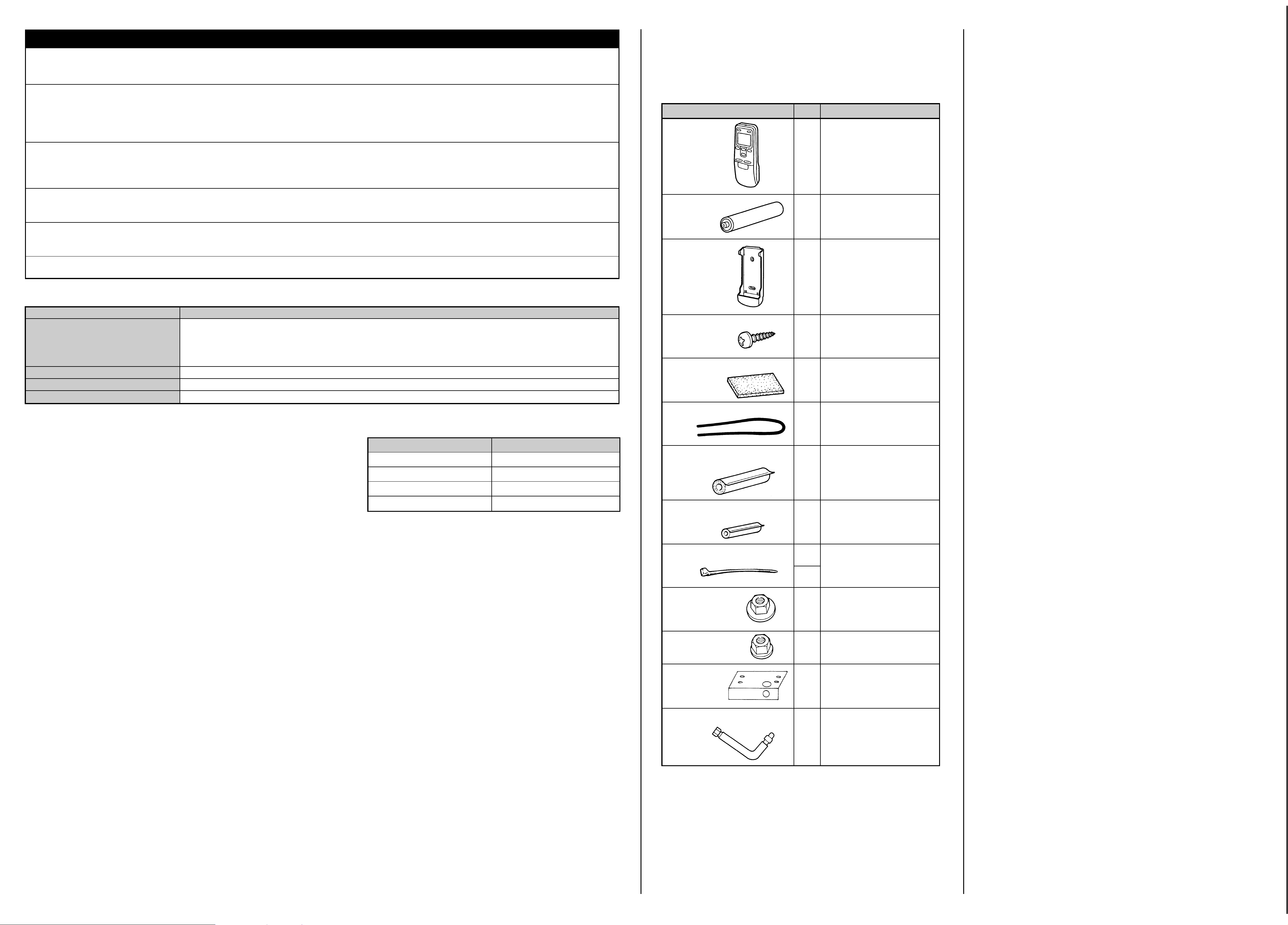
STANDARD PARTS
The following installation parts are furnished.
Use them as required.
INDOOR UNIT ACCESSORIES
Q’ty
1
2
1
2
1
1
2
1
Name and Shape
Remote
control unit
Battery (penlight)
Remote
control
unit holder
Tapping screw
(ø3 × 12)
Drain hose insulation
VT wire
Coupler heat insulator (large)
Coupler heat insulator (small)
Nylon fastener
Special nut A
(large flange)
Special nut B
(small flange)
Installation
template
Auxiliary pipe assembly
Application
Use for air conditioner
operation
For remote control unit
For mounting the remote
control unit
For remote control unit
holder installation
Adhesive type 70 × 230
For fixing the drain hose
L 280 mm
For indoor side pipe joint
(Gas pipe)
For indoor side pipe joint
(Liquid pipe)
For fixing the coupler heat
insulator
For installing indoor unit
For installing indoor unit
For positioning the indoor
unit
For connecting the piping
Large
4
Small
4
4
4
1
1
OPTIONAL PARTS
The following options are available.
••
••
• DRAIN PUMP UNIT: UTR-DPB241 (P/N 9034087001)
••
••
• WIRED REMOTE CONTROLLER UNIT: UTB-UUB (P/N 9075887004)
It is necessary to use seamless copper pipes and it is desirable that the amount of
residual oil is less than 40 mg/10 m. Do not use copper pipes having a collapsed,
deformed or discolored portion (especially on the interior surface). Otherwise, the
expansion valve or capillary tube may become blocked with contaminants.
As an air conditioner using R410A incurs pressure higher than when using
conventional refrigerant, it is necessary to choose adequate materials.
Thicknesses of copper pipes used with R410A are as shown in the table. Never
use copper pipes thinner than that in the table even when it is available on
the market.
6.35 mm (1/4 in.)
9.52 mm (3/8 in.)
12.70 mm (1/2 in.)
15.88 mm (5/8 in.)
0.80 mm (0.0315 in.)
0.80 mm (0.0315 in.)
0.80 mm (0.0315 in.)
1.00 mm (0.0394 in.)
Pipe outside diameter
Thickness
Page 3
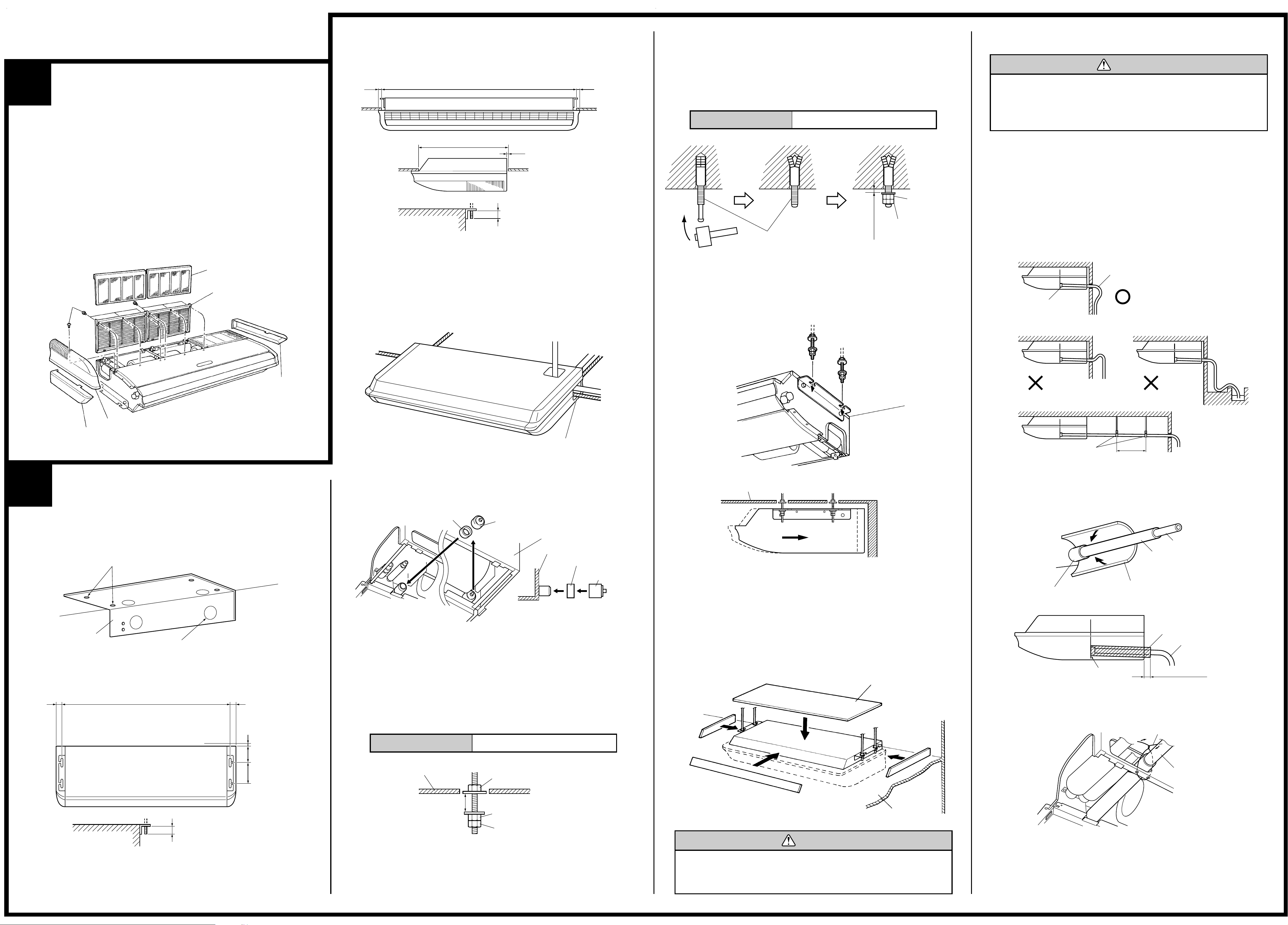
1
INSTALLATION PROCEDURE
2
PREPARING INDOOR UNIT
INSTALLATION
REMOVE THE INTAKE GRILLE AND SIDE COVER
(1) Remove the two Air filters.
(2) Remove the two Intake grilles.
• For 4 Left rear drain and 5 Left drain: Remove air filters and intake
grilles at three places. (Refer to “2 INDOOR UNIT INSTALLATION”.)
(3) Remove the Side cover A (Right side) and Side cover B (Right and
Left side).
• For 5 Left drain : Remove both the Side cover A (Right and Left
side). (Refer to “2 INDOOR UNIT INSTALLATION”.)
(4)
This air conditioner can be set up to intake fresh air. For information
about how to install for fresh-air intake, refer to “= FRESH-AIR INTAKE”.
INDOOR UNIT INSTALLATION
You can use the accessory template to help you install the indoor unit.
The template helps you determine the appropriate locations for suspension bolts and pipe opening (drain pipe and connection cord).
[For Half-Concealed Installation]
••
••
• Suspension-bolt pitch should be as shown in the figure.
2. SELECT PIPING DIRECTION
Select connection piping and drain piping directions.
[FOR 4 Left rear piping, 5 Left piping]
••
••
• Transfer the Drain cap and Drain cap seal.
Drain cap seal
Drain cap
Indoor unit
Drain pan
Drain cap seal
Drain cap
Push cap all the way on
(as far as it will go).
[If using anchor bolts]
(1) Drill holes for anchor bolts at the locations at which you will set the
suspension bolts. Note that anchor bolts are M10 bolts (to be obtained locally).
(2) Install the anchor bolts, then temporarily attach special nut “B” (in-
cluded) and a locally-procured M10 nut to each of the bolts.
Anchor-Bolt Strength 980 to 1470 N (100 to 150 kgf)
4. INSTALLING THE INDOOR UNIT
(1) Lift unit so that suspension bolts pass through the suspension fittings
at the sides (four places), and slide the unit back.
Wall
Ceiling
Ceiling
M10 Anchor Bolt
(Obtained locally)
Special nut B
(Included)
M10 Nut
(Obtained locally)
10 to 15 mm
(3/8" to 19/32")
1. LOCATION OF CEILING SUSPENSION BOLTS
Suspension bolt pitch 1600 mm (63")
Dimensions
(Space Required
for Installation)
30 mm (1-3/16")
10 mm (3/8")
155 mm (6-3/32")
300 mm (12")
INDOOR UNIT (TOP VIEW)
INDOOR UNIT
Suspension bolt should
extend outward 30 to 75 mm.
(1-3/16" to 2-31/32")
30 mm (1-3/16")
3. DRILLING THE HOLES AND ATTACHING THE
SUSPENSION BOLTS
(1) Drill ø25 mm holes at the suspension-bolt locations.
(2) Install the bolts, then temporarily attach Special nuts A and B and a
normal M10 nut to each bolt. (The two special nuts are provided with
the unit. The M10 nut must be obtained locally.) Refer to the figure.
Bolt Strength 980 to 1470 N (100 to 150 kgf)
Ceiling panel
Special nut A (Included)
Special nut B (Included)
M10 Nut (Obtained locally)
10 to 15 mm
(13/32" to 19/32")
INDOOR UNIT
Wall
Ceiling panel
(2) Fasten the indoor unit into place by tightening-up the special “B” bolts
and the M10 nuts. Make sure that unit is secure and will not shift back
and forth.
[For Half-Concealed Installation]
When installing the indoor unit in a semi-concealed orientation, make sure
to reinforce the insulation of the unit on all sides. Drops of water may fall
from the unit if it is not thoroughly insulated.
Glass wool insulate (10 to 20 mm
(3/8" to 3/4") thick)
INDOOR UNIT
(Top view)
Wall
Ceiling panel
CAUTION
Install the drain pipe in accordance with the instructions
in this installation instruction sheet and keep the area
warm enough to prevent condensation. Problems with the
piping may lead to water leaks.
••
••
• Install the drain pipe with downward gradient (1/50 to 1/100) and so
there are no rises or traps in the pipe.
••
••
• Use general hard polyvinyl chloride pipe (VP25) [outside diameter
38 mm (1-1/2")].
••
••
• During installation of the drain pipe, be careful to avoid applying
pressure to the drain port of the indoor unit.
••
••
• When the pipe is long, install supporters.
••
••
• Do not perform air bleeding.
••
••
• Always heat insulate (8 mm (5/16") or over thick) the indoor side of the
drain pipe.
GOOD
BAD BAD
Drain pipe
Arrange the drain pipe
lower than this portion.
Lifted up
Wave
End in water
Supporter
1.5 to 2 m
(5 to 6.5 ft)
(1) Install insulation for the drain pipe.
Cut the included insulation material to an appropriate size and adhere
it to the pipe.
Drain pipe
Insulation for drain pipe
(To be obtained locally. Length
should be at least 8 mm (5/16").)
Drain pipe insulation (accessories)
Indoor unit (drain port)
(2) If “1 Right rear piping” : fasten the drain pipe with VT wire so that the
pipe slopes correctly within the indoor unit.
Indoor unit (rear view)
VT wire
Drain hose
Drain pipe insulation
Drain pipe
No gap
10 mm (3/8") or over
Indoor unit
1 Right rear piping
5 Left piping
(Drain pipe only)
4 Left rear piping
(Drain pipe only)
2 Top piping
(Connection pipe only)
3 Right
piping
Cut off the piping outlet cutting groove
with a hacksaw, etc.
INDOOR UNIT (TOP VIEW)
Air filter
Intake grille
Tapping screw
INDOOR UNIT
Side cover A (Right side)
Side cover B
(Left side)
Side cover B (Right side)
Drilling position for Suspension bolt
Ceiling
Wall
Template
Drilling position for piping
Ceiling Opening: 1580 mm (62") 40 mm (1-9/16")
Ceiling panel
Ceiling Opening: 640 mm (25-3/16")
15 mm (19/32")
Suspension bolt should
extend outward 30 to 50 mm.
(1-3/16" to 1-31/32")
INDOOR UNIT
Ceiling panel
40 mm (1-9/16")
CAUTION
In order to check the drainage, be sure to use a level
during installation of the indoor unit. If the installation site
of the indoor unit is not level, water leakage may occur.
5. DRAIN PIPING
Page 4

- Continued on back -
CONNECTING THE PIPE
2. BENDING PIPES
CAUTION
1 To prevent breaking of the pipe, avoid sharp bends.
Bend the pipe with a radius of curvature of 150 mm
(6") or over.
2 If the pipe is bent repeatedly at the same place, it will
break.
CAUTION
1 Do not use mineral oil on flared part. Prevent mineral
oil from getting into the system as this would reduce
the lifetime of the units.
2 While welding the pipes, be sure to blow dry nitrogen
gas through them.
3 The maximum lengths of this product are shown in the
table. If the units are further apart than this, correct
operation can not be guaranteed.
1. FLARING
(1) Cut the connection pipe to the necessary length with a pipe cutter.
(2) Hold the pipe downward so that cuttings will not enter the pipe and
remove the burrs.
(3) Insert the flare nut (always use the flare nut attached to the indoor
and outdoor units respectively) onto the pipe and perform the flare
processing with a flare tool.
Use the special R410A flare tool, or the conventional flare tool.
When using conventional flare tools to flare R410A pipes, the dimension
A should be approximately 0.5 mm (1/32 in.) more than indicated in the
table (for flaring with R410A flare tools) to achieve the specified flaring.
Use a thickness gauge to measure the dimension A.
Pipe outside
diameter
Width across flats
of Flare nut
Width across flats
Check if [L] is flared uniformly
and is not cracked or scratched.
B
Die
A
Pipe
3. CONNECTION PIPES
Indoor unit
(1) Detach the caps and plugs from the pipes.
CAUTION
1 Be sure to apply the pipe against the port on the in-
door unit correctly. If the centering is improper, the flare
nut cannot be tightened smoothly. If the flare nut is
forced to turn, the threads will be damaged.
2 Do not remove the flare nut from the indoor unit pipe
until immediately before connecting the connection
pipe.
(2) Centering the pipe against port on the indoor unit, turn the flare nut
with your hand.
To prevent gas leakage, coat the flare
surface with alkylbenzene oil (HAB).
Do not use mineral oil.
(3) Remove the filter guide.
Indoor unit
Filter guide
(4) Attach the connection pipe.
Connection pipe (Liquid)
Indoor unit
Connection pipe (Gas)
• For 2 Top piping and 3 Right piping connections, use the Auxiliary
pipe (Gas pipe) provided.
2 Top piping
Connection pipe (Gas)
Indoor unit (rear)
Connection pipe (Gas)
3 Right piping
Auxiliary pipe (Gas pipe)
(5) When the flare nut is tightened properly by your hand, use a torque
wrench to finally tighten it.
Torque wrench
Holding spanner
Body side
CAUTION
Hold the torque wrench at its grip, keeping it in the right
angle with the pipe, in order to tighten the flare nut
correctly.
3
Flare nut Tightening torque
6.35 mm (1/4 in.) dia.
9.52 mm (3/8 in.) dia.
12.70 mm (1/2 in.) dia.
15.88 mm (5/8 in.) dia.
6.35 mm (1/4 in.)
9.52 mm (3/8 in.)
12.70 mm (1/2 in.)
15.88 mm (5/8 in.)
0 to 0.5 mm (0 to 0.0197 in.)
Pipe outside diameter
Dimension A
Flare tool for R410A, clutch type
6.35 mm (1/4 in.)
9.52 mm (3/8 in.)
12.70 mm (1/2 in.)
15.88 mm (5/8 in.)
9.1 mm (0.3583 in.)
13.2 mm (0.5197 in.)
16.6 mm (0.6536 in.)
19.7 mm (0.7756 in.)
Pipe outside diameter
Dimension B
6.35 mm (1/4 in.)
9.52 mm (3/8 in.)
12.70 mm (1/2 in.)
15.88 mm (5/8 in.)
17 mm (0.6693 in.)
22 mm (0.8661 in.)
26 mm (1.0236 in.)
29 mm (1.1417 in.)
The pipes are shaped by your hands. Be careful not to collapse them.
Do not bend the pipes in an angle more than 90
°.
When pipes are repeatedly bend or stretched, the material will harden,
making it difficult to bend or stretch them any more. Do not bend or
stretch the pipes more than three times.
16 to 18 N·m (160 to 180 kgf·cm)
30 to 42 N·m (300 to 420 kgf·cm)
49 to 61 N·m (490 to 610 kgf·cm)
63 to 75 N·m (630 to 750 kgf·cm)
0
-0.4
Page 5

POWER
SUPPLY
REMOTE
CONTROL
321
WARNING
1 Before starting work, check that power is not being
supplied to the indoor unit and outdoor unit.
2 Match the terminal board numbers and connection
cord colors with those of the outdoor unit.
Erroneous wiring may cause burning of the electric
parts.
3 Connect the connection cords firmly to the terminal
board. Imperfect installation may cause a fire.
4 Always fasten the outside covering of the connection
cord with the cord clamp. (If the insulator is chafed,
electric leakage may occur.)
5 Always connect the ground wire.
HOW TO CONNECT WIRING TO THE
TERMINALS
A. For solid core wiring
(1) Cut the wire end with a wire cutter or wire-cutting pliers, then strip
the insulation to about 25 mm (15/16") to expose the solid wire.
(2) Using a screwdriver, remove the terminal screw(s) on the terminal
board.
(3) Using pliers, bend the solid wire to form a loop suitable for the
terminal screw.
(4) Shape the loop wire properly, place it on the terminal board and
tighten securely with the terminal screw using a screwdriver.
B. For strand wiring
(1) Cut the wire end with a wire cutter or wire-cutting pliers, then strip
the insulation to about 10 mm (3/8") to expose the strand wiring.
(2) Using a screwdriver, remove the terminal screw(s) on the terminal
board.
(3) Using a round terminal fastener or pliers, securely clamp a round
terminal to each stripped wire end.
(4) Position the round terminal wire, and replace and tighten the
terminal screw using a screwdriver.
A. Solid wire
Strip 25 mm (15/16")
Insulation
Loop
B. Strand wire
Strip 10 mm (3/8")
Round
terminal
Wire
Screw with
special washer
Round terminal
Terminal
board
Wire
Screw with
special washer
Round
terminal
Terminal block
4
ELECTRICAL WIRING
1. CONNECTION DIAGRAMS
3. INDOOR UNIT
Indoor unit
Control box
Tapping screw
(2) Remove the Cover A and install the Connection cord.
(3) Reattach Cover A. Then fasten the control box back into its original
position using the two tapping screws.
Cover A
Control box
5
REMOTE CONTROL UNIT
INSTALLATION
1. REMOTE CONTROL UNIT HOLDER INSTALLATION
••
••
• Install the remote control unit holder to a wall or pillar with the tapping
screws.
Remote Control Unit
holder fixing
Remote Control
Unit mounting
Remote control
unit holder
Tapping
screws
(small)
1 Set
2 Push
Remote
control unit
2. SWITCHING REMOTE CONTROL UNIT SIGNAL
CODE
Jumper wire
JM3
Connect
Disconnect
Connect
Disconnect
Remote control unit
signal code
A (Primary setting)
B
C
D
JM2
Connect
Connect
Disconnect
Disconnect
2. CONNECTION CORD PREPARATION
Power supply cord
or connection cord
Control box
Terminal board
Connection cord
CAUTION
Use care not to mistake the power supply cord and
connection wires when installing.
(1) Remove the two tapping screws and pull the control box downward.
Confirm the setting of the remote control unit signal code and the printed
circuit board setting.
If these are not confirmed, the remote control unit cannot be used to
operate for the air conditioner.
30 mm (1-3/16")
40 mm or more
(1-9/16")
For earth
(5) Attach the connection cord and cable clips. Make sure that they are
positioned so that they will not interfere with opening and closing of
the intake grille or with removal and installation of the air filters.
CAUTION
1 Check that the indoor unit correctly receives the
signal from the remote control unit, then install the
remote control unit holder.
2 Select the remote control unit holder selection site by
paying careful attention to the following:
Avoid places in direct sunlight.
Select a place that will not be affected by the heat from
a stove, etc.
(4) Use lock nuts to secure the conduit tube.
Cable clip
Connection cord
Conduit
Lock nut
Earth screw
CAUTION
1 Be sure to refer the above diagram and do correct field
wiring.
Wrong wiring causes malfunction of the unit.
2 Check local electrical codes and also any specific
wiring instructions or limitation.
1
2
3
L
N
1
2
3
GG
1
2
3
INDOOR
INDOOR UNIT
OUTDOOR UNIT
TERMINAL
DISCONNECT
SWITCH
(FIELD
SUPPLY)
Grounding
line
14AWG
(Inter-unit)
Power lines
230/208 V
230/208 V
230/208 V
TERMINAL
Power supply line
Single-phase, 230/208 V
WARNING
Disconnect switch and circuit breaker for over current protection given in the table below is to be installed between
the indoor unit and the outdoor unit.
15A 240 V - 5A
Disconnect switch
Circuit breaker (or Fuse)
CIRCUIT
BREAKER
OR FUSE
(FIELD
SUPPLY)
Page 6

8
• Remote control unit settings
(1) Press the START/STOP button and display only the clock.
(2) Press the MASTER CONTROL button continuously for more than five
seconds to display the current signal code.
(3) Change the signal code with the
button ( ).
(4) Press the MASTER CONTROL button again to return to the clock
display and change the signal code.
JM1
JM2
JM3
Indoor unit
Printed circuit board
6
FINISHING
(1) Install the filter guide.
(2) Install the intake grilles.
(3) Install side covers A and B (if the unit is installed in a half-concealed
orientation, only install side cover A).
(4) Install the air filters.
7
CUSTOMER GUIDANCE
Explain the following to the customer in accordance with the operating
manual:
(1) Starting and stopping method, operation switching, temperature
adjustment, timer, air flow adjustment, and other remote control unit
operations.
(2) Air filter removal and cleaning.
(3) Give the operating manual and installation instruction sheet to the
customer.
TEST RUNNING
••
••
• Perform test operation and check items 1 and 2 below.
••
••
• For the operation method, refer to the operating manual.
••
••
• The outdoor unit may not run, depending on the room temperature.
In this case, the ‘TEST RUN’ signal is received during air conditioner
operation (use a metallic object to short the two metal contacts under
the battery compartment lid and send the ‘TEST RUN’ signal from the
remote control unit).
••
••
• To end test operation, press the remote control unit START/STOP
button.
(When the air conditioner is run by pressing the remote control unit
TEST RUN button, the OPERATION and TIMER lamps will simultaneously flash slowly.)
1. INDOOR UNIT
(1) Is operation of each button on the remote control unit normal?
(2) Does each lamp light normally?
(3) Do not air flow direction flap and louvers operate normally?
(4) Is the drain normal?
2. OUTDOOR UNIT
(1) Is there any abnormal noise and vibration during operation?
(2) Will noise, wind, or drain water from the unit disturb the neighbors?
(3) Is there any gas leakage?
9
AN ERROR DISPLAY
1. INDOOR UNIT
Operation can be checked by lighting and flashing of the display section
OPERATION, TIMER and VERTICAL SWING lamps.
Perform judgment in accordance with the following.
SWING SWING TIMER
OPERATION
MANUAL
AUTO
VERTICAL SWING lamp (Orange)
TIMER lamp (Green)
OPERATION lamp (Red)
• Test running
When the air conditioner is run by pressing the remote control unit test
run button, the OPERATION, TIMER and VERTICAL SWING lamps
flash slowly at the same time.
• Error
The OPERATION, TIMER and VERTICAL SWING lamps operate as
follows according to the error contents.
Indoor EEPROM abnormal
Outdoor EEPROM abnormal
Indoor room temperature sensor
open
Indoor room temperature sensor
shortcircuited
Indoor heat exchanger temperature
sensor open
Indoor heat exchanger temperature
sensor shortcircuited
Float switch operated
Indoor signal abnormal
Outdoor signal abnormal
Indoor fan abnormal
Outdoor power source connection
abnormal
Outdoor heat exchanger
temperature sensor open
Outdoor heat exchanger
temperature sensor shortcircuited
Outdoor temperature sensor open
Outdoor temperature sensor
shortcircuited
Outdoor discharge pipe temperature
sensor or compressor temperature
sensor open
Outdoor discharge pipe temperature
sensor or compressor temperature
sensor shortcircuited
Outdoor high pressure abnormal
Outdoor discharge pipe temperature
or compressor temperature sensor
abnormal
OPERATION
lamp (RED)
(2 times)
(2 times)
(3 times)
(3 times)
(4 times)
(5 times)
(5 times)
(6 times)
TIMER lamp
(GREEN)
(2 times)
(3 times)
(3 times)
(4 times)
(4 times)
(5 times)
(5 times)
(6 times)
(7 times)
SWING lamp
(ORANGE)
: 0.1s ON/0.1s OFF (flash) : OFF
: 0.5s ON/0.5s OFF (flash)
Short the two metal contacts
under the battery compartment lid.
Error contents
Page 7

FRESH-AIR INTAKE
(1) Open up the knockout hole for the fresh-air intake, as shown in the
figure. (If using half-concealed installation, open up the top knockout
hole instead.)
10
For half concealed
installation
Indoor unit
CAUTION
1 When removing the cabinet (iron plate), be careful not
to damage the indoor unit internal parts and surrounding area (outer case).
2 When processing the cabinet (iron plate), be careful
not to injure yourself with burrs, etc.
(2) Fasten the round flange (optional) to the fresh-air intake, as shown in
the figure. (If using half-concealed installation, attach to the top.)
[After completing “2 INDOOR UNIT INSTALLATION”...]
(3) Connect the duct to the round flange.
(4) Seal with a band and vinyl tape, etc. so that air does not leak from the
connection.
Round duct (option parts)
Duct
11
WIRED REMOTE CONTROL
UNIT SETTING (OPTIONAL)
RED
WHITE
BLACK
REMOTE
CONTROL
POWER
SUPPLY
123123
BEFORE INSTALL WIRED REMOTE CONTROL UNIT
••
••
• The wired remote control unit is an option. It isn't included in main body
of air-conditioner.
••
••
• When you use wired remote control unit, some functions may not be
used.
••
••
• please use the recommended wired remote control unit.
(Before installing, Please read the FEATURES AND FUNCTIONS section of OPERATING MANUAL to confirm the concerned contents.)
CAUTION
1 Before installing, be sure to disconnect all power sup-
ply.
2 Don't touch the heat exchanger.
3 During installing or removing operation, be sure not to
have wire catched by parts or draw it hard. Or it may
result troubles to the air-conditioner.
4 Avoid place in direct sunlight.
5 Select place that will not be affected by the heat from a
stove, etc.
6 Insure the length of wire is not over the recommended
maximum length.
7 Before setting up the wired remote control unit, please
confirm whether air-conditioner can receive the signal.
Remove the two screws on the bottom and then remove control box A.
••
••
• To use the optional wired remote control, set up the wiring as shown in
the diagram below.
••
••
• Use the clamps to fasten the remote control wire in three locations.
••
••
• Set up the wiring so that the remote control wire passes under the
capacitor and the plastic.
••
••
• Change the setting for the electrical circuits.
Switch 4 (SW4) on the printed circuit board inside the electric component box must be set as follows.
Attach the remote control wire and cable clips.
Do not group the connection cord and remote control wire together.
Control box
Control box A
Screw
RED
WHITE
REMOTE
CONTROL
BLACK
POWER
SUPPLY
231 231
Clamp
Remote control wire
Capacitor, Plastic
Clamp
Clamp
Control box
Terminal board
Cable clip
Cable clip
Connection cord
Remote control wire
Wires
CAUTION
1 When the optional wired remote control is used, please
refer to the wired remote control manual supplied with
the wired remote control.
2 When the unit is set for the optional wired remote con-
trol, the wireless remote control cannot be used.
3 When the unit is set for the optional wired remote con-
trol, MANUAL/AUTO switch on the indoor unit cannot
be used.
4 When the unit is set for the optional wired remote con-
trol, the Display Timer lamp (Green) on the indoor unit
will no longer light.
SW4
SW4 SW4
Wireless remote
control type
Wired remote
control type
SUMOTUWETH FR
SA
(1) Stop the air conditioner operation.
(2) Press the master control button and the fan control button simultane-
ously for 2 seconds or more to start the test run.
Unit number (usually 0)
Error code
(3) Press the start/stop button to stop the test run.
[SELF-DIAGNOSIS]
When the error indication “E:EE” is displayed, follow the following items to
perform the self-diagnosis. “E:EE” indicates an error has occurred.
REMOTE CONTROLLER DISPLAY
(1) Stop the air conditioner operation.
(2) Press the set temperature buttons
simultaneously for
5 seconds or more to start the self-diagnosis.
Refer to the following tables for the description of each error code.
Test run display
(3) Press the set temperature buttons simultaneously for
5 seconds or more to stop the self-diagnosis.
Ex. Self-diagnosis
Error code Error contents
Communication error
(indoor unit
remote controller)
Communication error
(indoor unit outdoor unit)
Room temperature sensor open
Room temperature sensor short-circuited
Indoor heat exchanger temperature sensor open
Indoor heat exchanger temperature sensor shortcircuited
Outdoor heat exchanger temperature sensor
Power source connection error
Float switch operated
Outdoor temperature sensor
Discharge pipe temperature sensor
Model abnormal
Indoor fan abnormal
00
01
02
03
04
05
06
08
09
0A
0c
11
12
TEST RUN
Page 8

Error code Error contents
Outdoor signal abnormal
Excessive outdoor pressure (permanent stop)
Compressor temperature sensor
Pressure switch error
IPM error
CT error
Active filter module (AFM) error
Compressor does not operate
Outdoor unit fan error
Communication error
(inverter multicontroller)
2 way valve sensor error
Expansion valve error
Connection indoor unit error
13
14
15
16
17
18
19
1A
1b
1c
1d
1E
1F
Indoor unit No. 0 Indoor unit No. 1 Indoor unit No. 2 Indoor unit No. 3
Remote
controller
wire
Remote
controller
(2) Rotary switch setting (indoor unit)
Set the unit number of each indoor unit using the rotary switch on the
indoor unit circuit board.
The rotary switch is normally set to 0.
(3) DIP switch setting (remote controller)
Change DIP switch 1 No. 3 on the remote controller from OFF to ON.
Indoor unit
Rotary Switch
Remote controller
DIP Switch 1
2. DUAL REMOTE CONTROLLERS (OPTIONAL)
Two separate remote controllers can be used to operate the indoor units.
(1) Wiring method (indoor unit to remote controller)
(2) DIP switch setting (remote controller)
Set the remote controller DIP switch 1 No. 1 and 2 according to the
following table.
Number of
remote
controllers
Master unit
1 (Normal)
2 (Dual)
ON
OFF
OFF
OFF
DIP-SW 1 No. 1
DIP-SW 1 No. 2
Remote controller
DIP Switch 1
Number of
remote
controllers
Slave unit
1 (Normal)
2 (Dual)
–
ON
–
ON
DIP-SW 1 No. 1
DIP-SW 1 No. 2
SW3
1 2 3
1 2 3
1 2 3
ONOFF
1
2
3
4
5
6
ON
1 2 3 1 2 3 1 2 3
1 2 3
1 2 3
ONOFF
1
2
3
4
5
6
1. GROUP CONTROL SYSTEM
A number of indoor units can be operated at the same time using a single
remote controller.
(1) Wiring method (indoor unit to remote controller)
SPECIAL INSTALLATION METHODS
CAUTION
1 When setting the rotary switch and DIP switches, do
not touch any other parts on the circuit board directly
with your bare hands.
2 Be sure to turn off the main power.
Remote
controller
wire
Indoor unit
Master
unit
Slave
unit
Remote
controller
PART NO. 9364488028
NO.
SW state
Detail
OFF ON
1 Invalidity Validity
★
Auto restart setting
2— —
★
Temperature correction
3— —
★
setting
1 Wireless
★
Wired Remote controller setting
2—
★
—
Air flow setting
3—
★
—
DIP-Switch 1
● Indoor unit
● Remote controller
[DIP-SWITCH SETTING]
DIP-Switch 4
3. AUTO RESTART
• When the air conditioner power was temporarily turned off by a power
failure etc., it restarts automatically after the power recovers.
(Operated by setting before the power failure)
The auto restart function can be
canceled.
(1) DIP switch setting (indoor unit)
Change the DIP switch (SW1-1)
on the indoor unit circuit board
from ON to OFF. The auto restart
function will be canceled.
Indoor unit
O
F
F
1
2
3
OFF
SW1
O
F
F
1
2
3
SW4
DIP Switch
(★: Factory setting)
ON
★
Multiple units
Cooling only model
★ Validity
Validity
Invalidity
Invalidity
Invalidity
Invalidity
Detail
Dual remote controller setting
Group control setting
Model setting
AUTO changeover setting
Memory Backup setting
THERMO SENSOR button setting
ENERGY SAVE button setting
Horizontal airflow direction and swing button setting
Vertical airflow direction and swing button setting
Cannot be used.
Cannot be used.
No.
1
2
3
4
5
6
1
2
3
4
5
6
OFF
★
★ One unit
★
Heat & cool model
Invalidity
★ Invalidity
★ Validity
★ Validity
★ Validity
★ Validity
★ Fixed at OFF
★ Fixed at OFF
SW state
DIP-
switch 1
DIP-
switch 2
 Loading...