

Page 1
SPLIT TYPE
ROOM AIR CONDITIONER
FLOOR CONSOLE /
UNDER CEILING
DUAL
type (60Hz)
Models
Indoor unit
Outdoor unit
MS24Y3F MR24UY3F
CONTENTS
SPECIFICATIONS
OUTLINE AND DIMENSIONS
REFRIGERANT SYSTEM DIAGRAM
CIRCUIT DIAGRAM
PCB CIRCUIT DIAGRAM
ERROR CONTENTS
DISASSEMBLY ILLUSTRATION (Indoor Unit)
DISASSEMBLY ILLUSTRATION (Outdoor Unit)
PARTS LIST (Indoor Unit)
PARTS LIST (Outdoor Unit)
STANDARD ACCESSORIES
................................
.....................
..............
..............................
........................
............................
.......................
......................
.....................
.....
....
1
2
4
5
7
11
13
20
24
25
26
Page 2
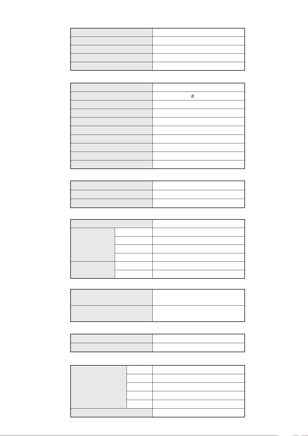
SPECIFICATIONS
TYPE
INDOOR UNIT
OUTDOOR UNIT
COOLING CAPACITY
HEA TING CAPACITY
ELECTRICAL DATA
POWER SOURCE
FREQUENCY
RUNNING CURRENT (Cool)
RUNNING CURRENT (Heat)
INPUT WATTS (Cool)
INPUT WATTS (Heat)
E.E.R. (Cool)
E.E.R. (Heat)
MOISTURE REMOVAL
AIR CIRCULATION-High
COMPRESSOR
TYPE
Cool and Heat
MS24Y3F
MR24UY3F
22,200 / 22,200 BTU/h
24,200 / 24,200 BTU/h
230 V / 208 V
160Hz
9.8 A / 10.9 A
10.2 A / 11.3 A
2.25 kW / 2.25 kW
2.33 kW / 2.33 kW
2.89 / 2.89 kW/kW
3.05 / 3.05 kW/kW
3.5 l/hr
3
/hr
880 m
Hermetic type, 4 poles, Inverter, Twin Rotary
DISCRIMINA TION
REFRIGERANT
FAN MOTOR
POWER SOURCE
INDOOR UNIT
( Cool / Heat )
OUTDOOR UNIT
( Cool / Heat )
DIMENSIONS
INDOOR UNIT
OUTDOOR UNIT
WEIGHT
INDOOR UNIT
R410A
DISCRIMINATION
HIGH-SPEED
MED-SPEED
LOW-SPEED
DISCRIMINATION
HIGH- SPEED
HxWxD
HxWxD
Gross / Net
TNB220FPBM9
4 lb 3 oz (1,900 g)
230 V
MFA-24PPT
1,180 / 1,100 r.p.m.
1,000 / 1,000 r.p.m.
900 / 900 r.p.m.
MFE-45ROM
850 / 900 r.p.m.
7-7/8" x 39-1/8" x 25-7/8" inch
(199 x 990 x 655 mm)
32-3/4" x 35-1/2" x 13" inch
(830 x 900 x 330 mm)
37 kg / 28 kg
OUTDOOR UNIT
Gross / Net
REFRIGERANT CHARGE (R410A)
Pipe Length
FULL CHARGE AMOUNT
ADDITIONAL REFRIGERANT
49 ft. (15 m)
66 ft. (20 m)
98 ft. (30 m)
131 ft. (40 m)
164 ft. (50 m)
12006.05.29
70 kg / 64 kg
4 lb 3 oz (1,900 g)
4 lb 10 oz (2,100 g)
5 lb 8 oz (2,500 g)
6 lb 6 oz (2,900 g)
7 lb 5 oz (3,300 g)
0.424 oz / ft. (40g/m)
Page 3
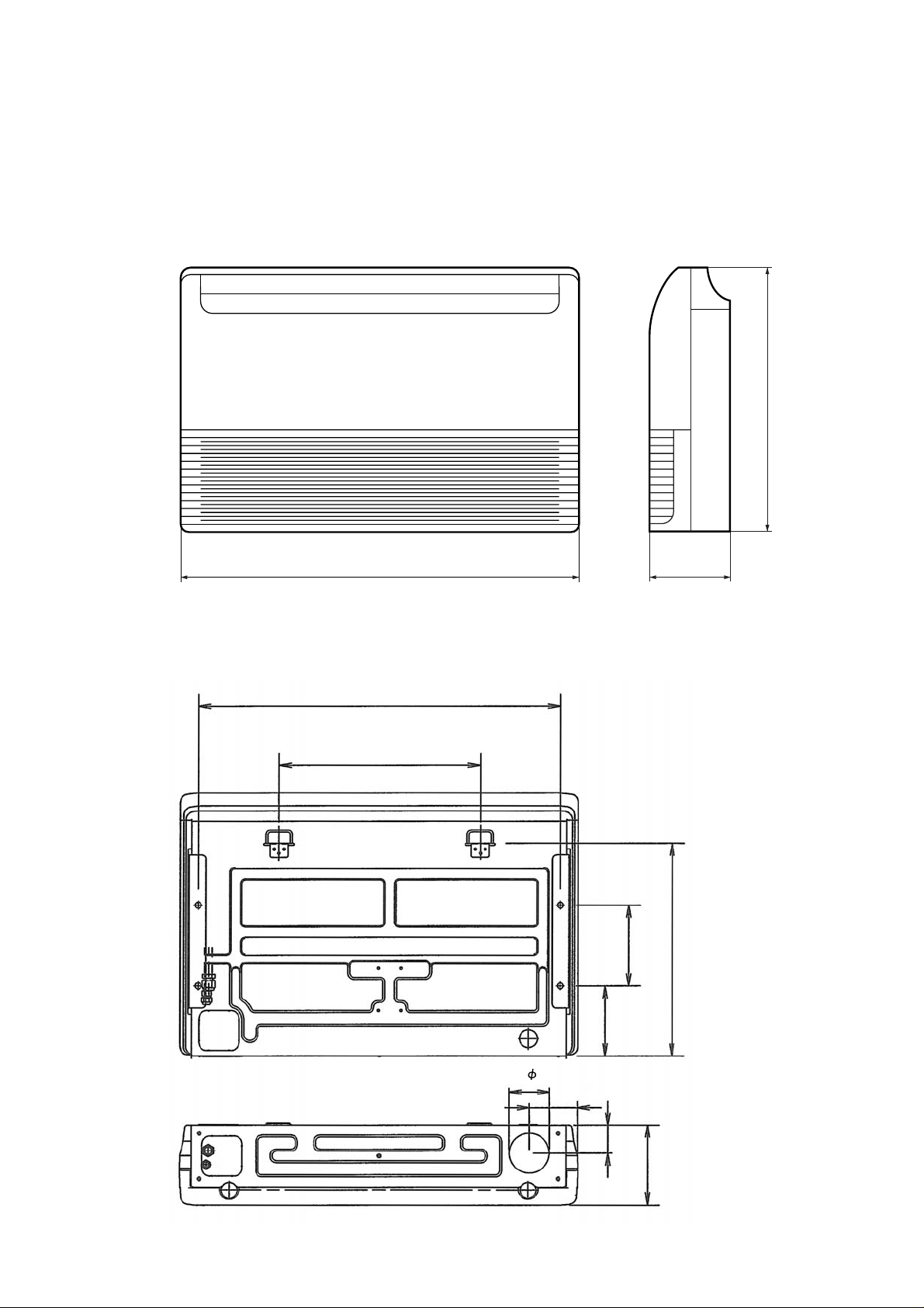
OUTLINE AND DIMENSIONS
INDOOR UNIT
Unit : inch (mm)
25-7/8" (655)
(rear view)
39-1/8" (990)
7-7/8" (199)
35" (900)
19-3/4" (500)
7-7/8" (200)
20-7/8" (530)
3-15/16" ( 100)
22006.05.25
6-7/8"
4-23/32" (120)
2-3/4" (70)
(175)
7-27/32" (199)
Page 4
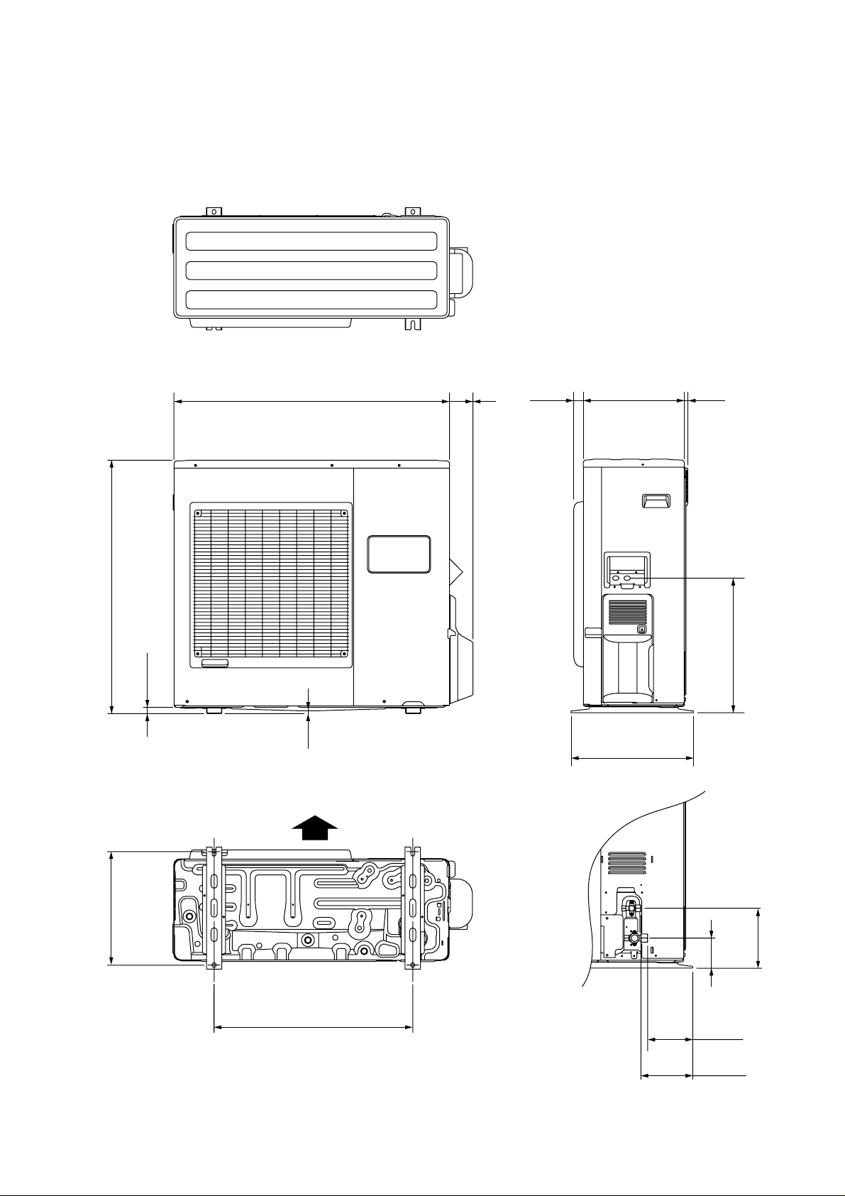
OUTDOOR UNIT
Unit : inch (mm)
32-3/4" (830)
7/8" (21)
35-1/2" (900)
3/8"
(9)
3"(77)
1-1/4"
(31)
13" (330)
15-3/4" (400)
1/2"
(12)
17-3/8" (440)
14-5/8" (370)
Air Flow
25-5/8" (650)
3-7/8"
(99)
7-3/4" (196)
5-3/4" (147)
6-3/4" (170)
32006.05.25
Page 5
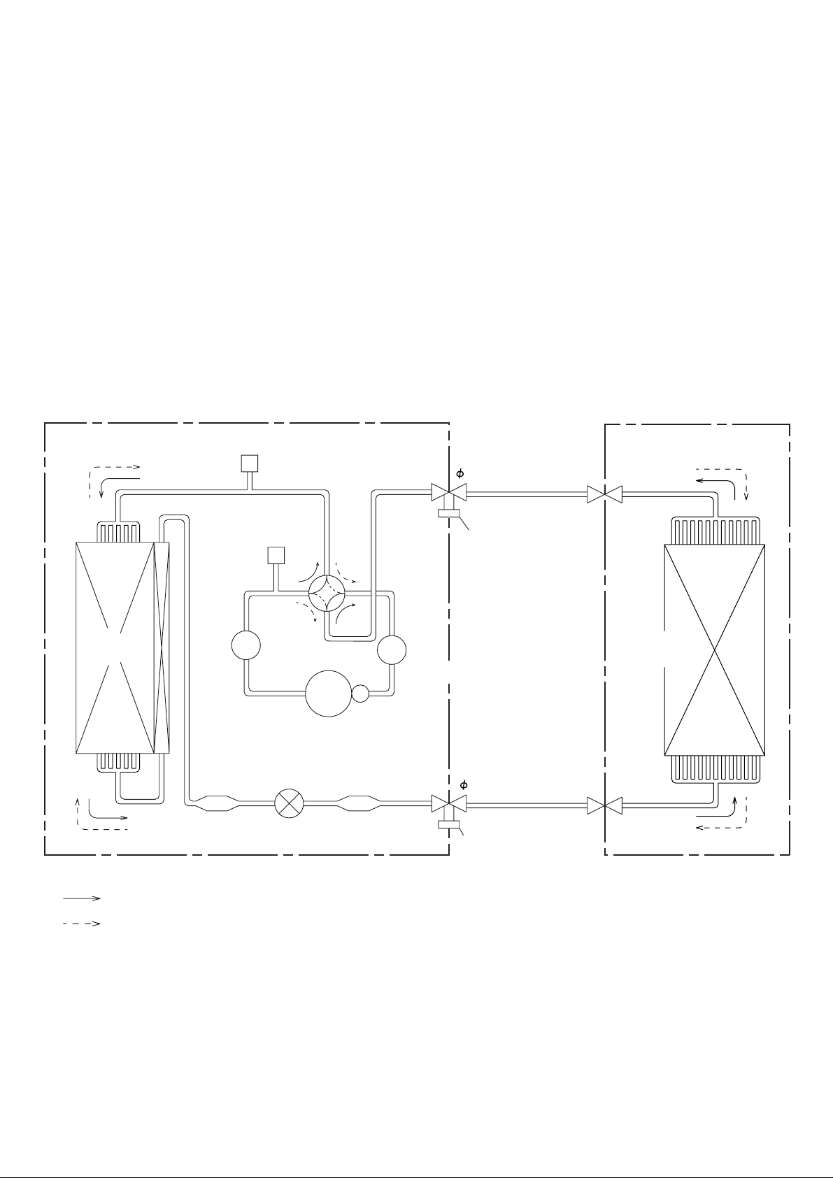
REFRIGERANT SYSTEM DIAGRAM
OUTDOOR UNIT
Condenser
Pressure
Check Valve
High Pressure
Switch
4-way
Muffler
Valve
Expansion
Valve
INDOOR UNIT
Refrigerant Pipe
15.88mm (5/8")
Charging
Valve
Evaporator
Accumulator
Compressor
Refrigerant Pipe
9.52mm (3/8")
: COOL
: HEAT
Strainer
Strainer
Charging Valve
42006.05.25
Page 6
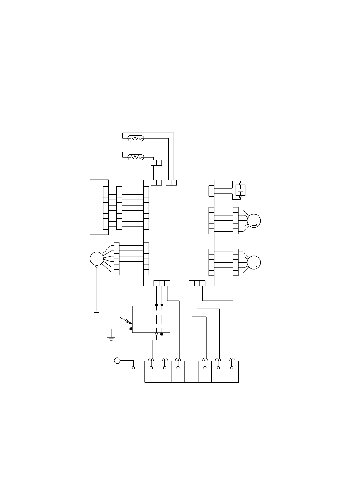
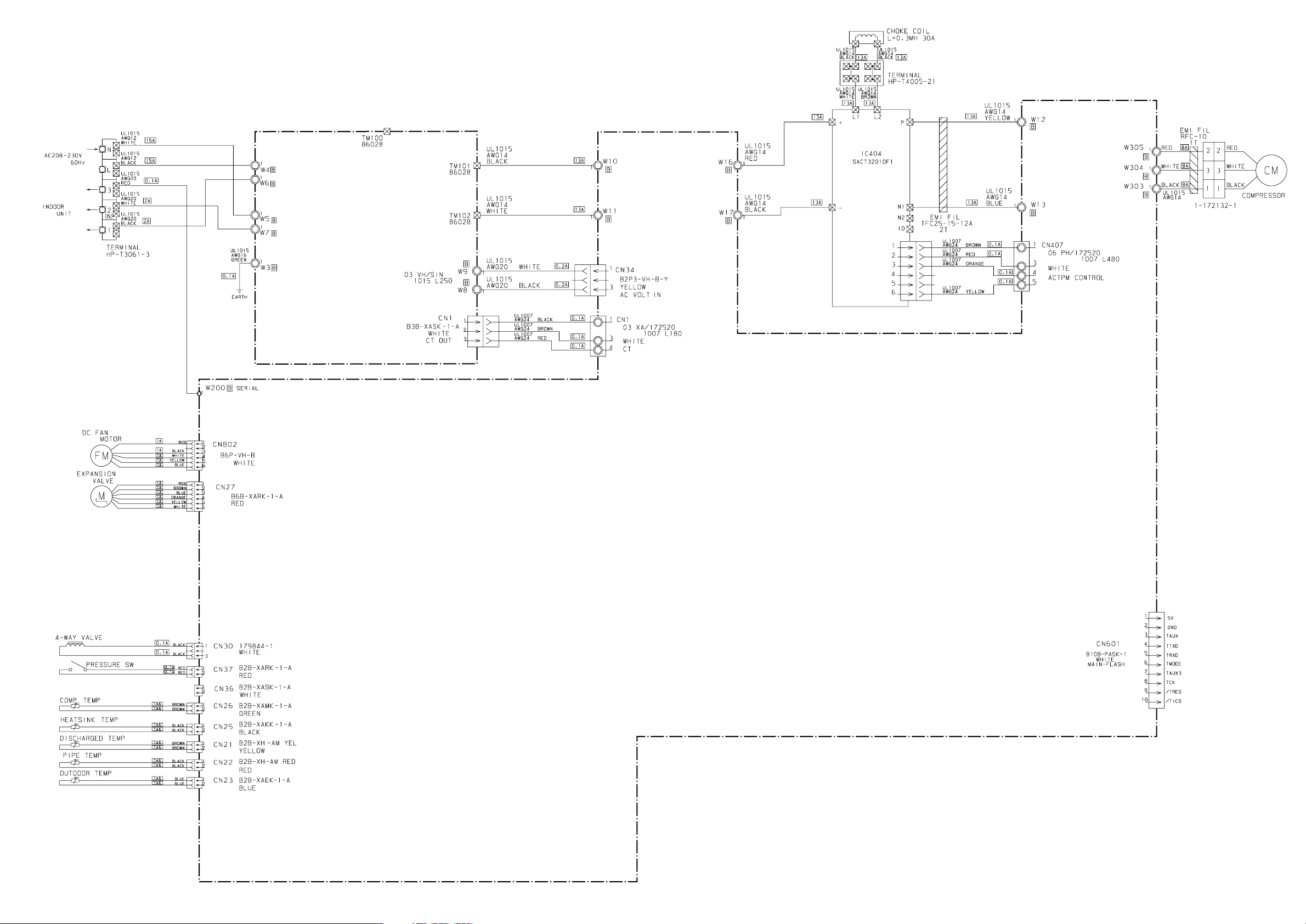
CIRCUIT DIAGRAM
INDOOR UNIT
ROOM TEMPERATURE THERMISTOR
PIPE TEMPERATURE THERMISTOR
1
CN7 CN8
1
2
3
4
5
6
7
8
1
2
3
4
5
6
FAN MOTOR
INDICATOR PCB ASSY
FM
1
2
3
4
5
CN201
6
7
8
1
2
3
4
5
6
7
8
BLACK
4
WHITE
6
RED
3
PINK
5
PURPLE
2
BLUE
1
BROWN
RED
ORANGE
YELLOW
WHITE
BLUE
PURPLE
GRAY
1
2
BLACK
BLACK
GRAY
GRAY
2
2
1
CN13CN5
CONTROLLER PCB ASSY
CN1 CN17
123
123
1
2
1
2
3
CN10 CN4
4
5
1
2
3
CN11
4
5
WHITE
WHITE
BROWN
RED
ORANGE
YELLOW
WHITE
BROWN
RED
ORANGE
YELLOW
WHITE
1
2
3
4
5
1
2
3
4
5
FAN MOTOR
CAPACITOR
STEP MOTOR
M
(UP/DOWN)
STEP MOTOR
M
( LEFT / RIGHT )
GREEN / YELLOW
Use T3.15A-250V
Fuse on F101
GREEN
POWER SUPPLY PCB
G
RED
WHITE
BLACK
L
N
WHITE
WHITE
BLACK
31
2
1
RED
BLACK
TERMINAL
3
2
52005.05.25
Page 7
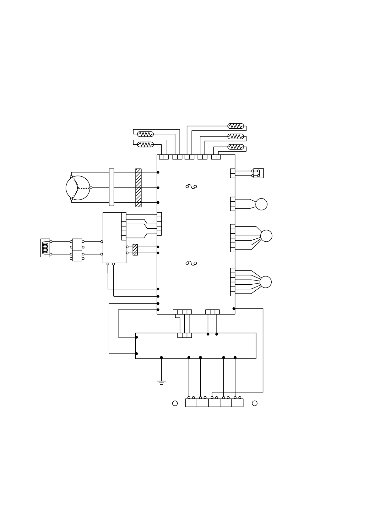
OUTDOOR UNIT
COMPRESSOR
BLACK
BLACK
CHOKE COIL
PIPE TEMPERATURE
THERMISTOR
DISCHARG TEMPERATURE
THERMISTOR
CONNECTOR
U
W
RED RED
WHITE
V
BLACK
ACTIVE
FILTER
MODULE
TERMINAL
WHITE
BROWN
L1
L2
+
-
EMI FILTER
WHITE
BLACK
BROWN
1
RED
2
ORANGE
3
4
5
YELLOW
6
P
N
EMI FILTER
1T
YELLOW
2T
BLACK
BLACK
BROWN
12 12 12 12 12
CN21
CN22
U
W305
V
W304
F4 T 5A-250V
W
W303
1
CONTROLLER PCB ASSY
2
CN407
3
4
5
W12
BLUE
W13
F2 T 3.15A-250V
RED
W16
W17
W10
CN1
W11
1
CN23
FUSE
FUSE
432
CN26
BLUE
BROWN
CN25
CN34
1
BLACK
CN37
CN30
CN802
CN27
W200
32
OUTDOOR TEMPERATURE
THERMISTOR
COMPRESSOR TEMPERATURE
THERMISTOR
HEAT SINK TEMPERATURE
THERMISTOR
RED
1
RED
2
BLACK
1
2
BLACK
3
RED
1
2
BLACK
3
WHITE
4
YELLOW
5
BLUE
6
RED
1
BROWN
2
BLUE
3
ORANGE
4
YELLOW
5
WHITE
6
HIGH PRESSURE SWITCH
4WV
SOLENOID COIL
FM FANMOTOR
EXPANSION VALVE COIL
EV
WHITE
BLACK
BLACK
BROWN
RED
32
TM102
1
CN1
POWER SUPPLY PCB ASSY
TM101
W3
GREEN
EARTH EARTH
W6 W7
BLACK
13LN
GG
WHITE
2 (N)
WHITE
W9 W8
BLACK
W4
BLACK
W5
WHITE
RED
62005.05.25
Page 8
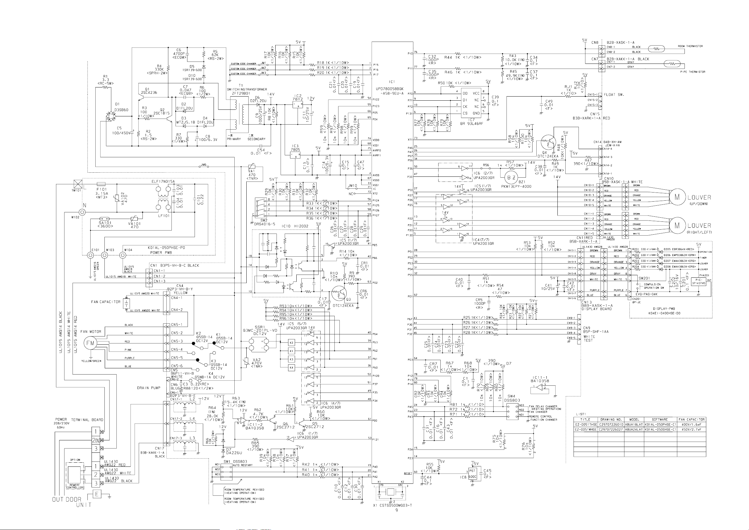
INDOOR PCB CIRCUIT DIAGRAM
CONTROLLER PCB ASSY
K01AL-050SHSE-C1
72006.05.25
Page 9
OUTDOOR PCB CIRCUIT DIAGRAM
POWER SUPPLY PCB ASSY
K04BA-0500HUE-P0
INVERTER ASSEMBLY
EZ-005FHUE
CONTROLLER PCB ASSY
K04AW-0502HUE-C1
82006.05.25
Page 10

OUTDOOR UNIT
CONTROLLER PCB ASSEMBLY
K04AW-0502HUE-C1
600/450V x 4
92006.05.25
Page 11

OUTDOOR UNIT
POWER SUPPLY PCB ASSEMBLY
K04BA-0500HUE-P0
TM100
POWER SOURCE
230V
60Hz
TO INDOOR UNIT
EARTH
AC VOLT OUT
BLACK
WHITE
W4
W5
W6
BLACK
W7
WHITE
W3
GREEN
W8
BLACK
W9
WHITE
RCH4730-021PF07
L1
B
VA101
470V
<TNR>
VA102
470V
<TNR>
B
C101
3.3
<LE>
SA100
RA-302M
B
B
B
B
B
C104
0.033
<YE>
C105
0.033
<YE>
C106
3.3
<LE>
L2
N200500K1D7C
C107
3.3
<LE>
CT1
CT-1B
D60
5V
DAN217U
220/16V
R60 1.0K
<1/10W>
(1%)
C60
<PJ>
L4
RCH4730-021PF07
+
VR1
B2K
R61 3.74K
<1/10W>
(1%)
C111
3.3
<LE>
R68 22K
<1/10W>
C64
0.1
<F>
C112
0.015
<YE>
C113
0.015
<YE>
C65
0.1
<F>
5V
TM101
TM102
CN1
B3B-XASK-1-A
WHITE
1
2
3
CT OUT
2006.05.29 10
Page 12

ERROR CONTENTS
(Indoor unit)
OERATION
TIMER
SWING
SWING
MANUALAUTO
OPERATION lamp (Red)
TIMER lamp (Green)
SWING lamp (Orange)
SWING lamp (Orange)
Operation can be checked by lighting and flashing of the display section OPERATION, , and
TIMER lamps.
Perform judgment in accordance with the following.
TEST RUNNING
When the air conditioner is run by pressing the remote control unit test run button, the OPERATION and
TIMER lamps flash slowly at the same time.
ERROR
The OPERATION, TIMER, and SWING lamps operate as follows (Table) according to the error contents.
Error contents
Indoor unit circuit board error
Indoor unit room temperature sensor wire opened
Indoor unit room temperature sensor wire short circuited
Indoor unit piping sensor wire opened
Indoor unit piping sensor short circuited
Indoor unit fan error 6 times
Outdoor unit circuit board error
Miswiring between outdoor unit and indoor unit
Outdoor unit discharge temperature sensor error
Outdoor unit piping sensor error
OPERATION TIMER SWING
(RED) (GREEN) (ORANGE)
2 times
2 times
3 times
3 times
5 times
5 times
Error display
5 times
3 times
Outdoor unit outdoor temperature sensor error 4 times
Fast flashing
:
Slow flashing
:
Off
:
112006.05.24
Page 13

ERROR CONTENTS
(outdoor unit)
1. Make a TEST RUN in accordance with the installation instruction sheet for the indoor unit.
2. OUTDOOR UNIT LEDS
When a malfunction occurs in the outdoor unit, the LED on
the circuit board lights to indicate the error. Refer to the following table for the description of each error according to the
LED.
LED
1 flash
2 flash
3 flash
4 flash
7 flash
8 flash
9 flash
12 flash
13 flash
14 flash
15 flash
16 flash
lighting
Communication error
(Indoor unit - Outdoor unit)
Discharg pipe temperature sensor
Outdoor heat exchanger temperature sensor
Outdoor temperature sensor
Compressor temperature sensor
Heat sink temperature sensor
Pressure switch abnormal
IPM error
Compressor rotor position cannot detect
Compressor cannot operate
Outdoor fan abnormal (upper fan)
Outdoor fan abnormal (lower fan)
No error
Error contents
2. When the product is operating:
1
Press the PUMP DOWN switch on the outdoor unit.
The LED on the outdoor unit circuit board lights, and
operation stops. At this point, recovery has not been
completed, so do not close the two- and three-way
valves.
The pump down operation (cooling operation) be-
2
gins after three minutes. Close the three-way valve
(liquid) after operation starts.
After2-3minutes, operation stops. Close the three-
3
way valve (gas) within one minute after operations
stops.
The LED will go out three minutes after it stops. Dis-
4
connect the power supply after confirming that the
LED has gone out.
*When the pump down operation is repeated, temporarily disconnect
the power supply after opening the closed valves (both liquid and gas).
Reconnect the power supply after2-3minutes and perform the pump
down operation.
*When the start of the operation after pump down operation has been
completed, temporarily disconnect the power supply after opening the
closed valves (both liquid and gas).
Reconnect the power supply after 2-3 minutes and be sure to perform
a test operation for cooling.
3-way valve
(Liquid)
SPECIAL INSTALLATION
SETTING
PUMP DOWN (Refrigerant collecting operation)
Perform the following procedures to collect the refrigerant
when moving the indoor unit or the outdoor unit.
1. When the product is stopped:
1
Press the PUMP DOWN switch on the outdoor unit.
(The LED on the outdoor unit circuit board lights.)
The pump down operation (cooling operation) be-
2
gins right away. After oparation starts, close the
three-way valve (liquid).
3
After2-3minutes, operation stops. Close the threeway valve (gas) within one minute after operations
stops.
4
The LED will go out three minutes after it stops.Disconnect the power supply after confirming that the
LED has gone out.
3-way valve
(Gas)
PUMP DOWN SW (SW2)
DANGER
This part (Choke coil) generates high voltages.
Never touch this part.
122006.02.14
Page 14

DISASSEMBLY ASSEMBLY
INDOOR UNIT
653-2
509
173
365-1
870-1
365-2
580
365-2
870-1
240
653-2
743
174
365-1
508
132006.05.25
Page 15

INDOOR UNIT
470
764
439
160
577
418
127
196-1
124
235
68
138
184-1
124
187
108
578
68
142006.05.25
Page 16

INDOOR UNIT
983
983
152006.05.25
Page 17

INDOOR UNIT
416
385
417
771
488
8-1
472
443
473
162006.05.25
Page 18

INDOOR UNIT
146
735
652-1
800
OPTIONAL PARTS
172006.05.29
Page 19

INDOOR UNIT
982
182006.06.13
Page 20

INDOOR UNIT
503
408
520
554
555
876-2
684
558
500
521
505
876-1
505
505
361-2
407
361-2
361-3
361-2
502
361-3
69
69
506
505
361
361-2
320
361-3
69
69
321
192006.05.29
Page 21

OUTDOOR UNIT
1
6
3
4
2
5
202006.05.29
Page 22

OUTDOOR UNIT
10
9
15
13
14
11
17
18
8
2006.06.13 21
Page 23

OUTDOOR UNIT
26
23
19
22
31
24
25
27
28
12
29
12
30
20
222006.05.29
Page 24

OUTDOOR UNIT
35
38
37
36
33 34
232006.05.29
Page 25

PARTS LIST
a
INDOOR UNIT
Ref. Part No. Ord. Ref. Part No. Ord.
No MS24Y3F Q'ty No MS24Y3F Q'ty
8-1 Air Filter 67220192 500 Protect Cover 67220242
34 Capacitor (Fan Motor) 67220218 502 SupportStay 67220243
56 Sirocco Fan Assy 67220193 503 LouverShaft 67220244
67 Rubber (Vibration-proof) 67220219 505 LouverStopper 67220004
68 Cap, Plastic 67220220 506 Louver Rod 67220007
69 Louver 67220008 508 Cosmetic Panel-R 67220245
108 Base Assy 67220013 509 Cosmetic Panel-L 67220246
109 Casing, Plastic 67220002 514 Control Box Cover 67220247
124 Kit (Dew Proof Plate) 67220221 520 Flap Base 67230058
126 Motor Fixing Table Assy 67220222 521 LouverLink Cover 67220006
127 Drain Hose Assy 67220015 554 Flap Link-Upper (Step Motor-V) 67220248
138 Kit (Separate Wall-A) 67220215 555 Flap Link-Lower (Step Motor-V) 67220249
146 EvaporatorAssy KB07 67220216 558 Motor Rod-A (Step Motor-V) 67220250
160 Drain Pan Assy (Kit) 67220217 577 Catch TL-119 67220014
164 Fan Motor Assy-IN 67220224 578 Base Bracket (Reinforcement Met
173 HangerBracket-L 67220228 580 Top Cover 67220001
174 HangerBracket-R 67220225 581 Protector, Metal (Fan Motor) 67220252
184-1 Thermistor Spring-A 67206400 625 Cord Bushing KR-51 67230030
187 Clamp No. 1219 67220226 628 Locking Spacer-B 67207461
195 Clamp SKB-100 67220227 652-1 Thermistor Holder Pipe 67206704
196-1 Clamp SKB-3M 67207409 653-2 Bolt 67220253
223 Control Box 67220229 684 Motor Base 67220254
234 Thermistor Assy-Room 67203510 731 Holder (Guide Rail) 67200566
235 Thermistor Assy-Pipe 67203511 735 Distributor Assy 67220255
236 Controller PCB Assy 67203712 743 Remote Control Unit Holder 67203202
(K01AL-050SHSE-C1)
240 Remote Control Unit 37220230 764 Drain Cap 67220256
320 Flap (Upper)-G 67230061 771 Panel 67220257
321 Flap (Lower) 67230062 800 Bypass Pipe Assy 67220258
338 Motor Fixture 67200588
361 Bushing 67210058
361-2 Bushing-B, Plastic 67230060
361-3 Bushing-C, Plastic 67230059
365-1 Special Screw 67220231
365-2 Special Screw 67220232
381 Locking Spacer, KGLS-4S 67207460
385 Indicator PCB Assy 67230056
407 Motor Rod 67220233
408 LouverLink 67220005
416 Insulation (Panel)-A 67220234
417 Insulation (Panel)-B 67220235
418 Insulation (Flap Base) 67220236
439 Drain Pan Wire 67220237
443 Arm Bracket 67220238
470 Separate Wall-B (Kit) 67220239
472 Grille Support 67220240
473 Filter Bracket 67220241
488 Grill-G 67220000
(K01AL-050SHSE-C1)
755 Casing Cover 67220003
DescriptionDescription
67220251
2006.06.13 24
Page 26

OUTDOOR UNIT
Ref. Part No. Ord.
No MR24UY3F Q'ty
1 Top Panel Sub Assy 67201640
2 Front Panel 67201601
3 Fan Guard 67201602
4 Grip Side 67201603
5 Service Panel Sub Assy 67201688
6 Right Panel 67201605
8 Propeller Fan Assy 67201607
9 Motor, Induction 67201608
10 Condenser-A Assy 67201609
11 CoilChoke 67201633
12 Strainer Assy 67201611
13 Separate Wall Assy 67201647
14 Cap Foot 67201650
15 Base Assy 67201648
17 3-Way Valve Assy (3/8) 67201614
18 3-Way Valve Assy (5/8) 67201615
19 Check Joint Assy 67201616
20 CompressorAssy 67201689
22 4-Way Valve 67201619
23 Solenoid 67201681
24 Pressure Switch 67201621
25 Inlet Pipe Cond A Assy 67201622
26 Inlet Pipe Cond B Assy 67201690
27 Outlet Pipe Cond A Assy 67201691
28 Expansion Valve Assy 67201692
29 Coil (Expansion Valve) 67201422
30 Distributor 67201693
31 Discharge Pipe A Assy 67201694
33 Terminal2P 67220181
34 Terminal5P 67201632
35 ACTPM 67201627
36 Holder Thermo 67201628
Description
37 Inverter PCB Assy 67201695
38 Power PCB Assy 67201696
---- Fuse 3.15A-250V 67201697
---- Thermistor (Outdoor Temp.) 67201686
---- Heat Exchanger Thermistor 67201698
---- Thermistor (Discharge) 67201635
---- Compressor Thermistor 67201637
---- Thermistor 67201430
---- Heatsink Thermistor 67201685
---- Transformer 67201699
---- Varistor 67201700
---- Arrester 67201701
---- Relay 67201702
---- Relay 67201703
---- Switch Push 67201704
---- Switch Slide 67201705
---- Drain Pipe Assy 67201706
---- Drain Cap 67201707
2006.05.25 25
Page 27

STANDARD ACCESSORIES
The following installation parts are furnished. Use them as required.
INDOOR UNIT ACCESSORIES
Name and Shape Part No.Application
Cosmetic Panel-L
Cosmetic Panel-R
Tapping screw ( 4 x 10)
Installation template
Hanger bracket (left)
Hanger bracket- (right)
Anchor bolt (M12)
Special nut
Q'ty
1
1
2
For positioning the indoor unit.
For under ceiling type.
1
For suspending the indoor unit from
1
ceiling.
1
4
4
9358536018
9358535011
0700009037
9359107002
9358596005
9358595008
313806339400
Spring washer
Wall bracket
Tapping screw ( 4 x 20)
Coupler heat insulator (large)
Coupler heat insulator (small)
Nylon fastener
Drain hose
Insulation (drain hose)
4
For suspending the indoor unit on
2
the wall.
For fixing the wall bracket.
6
For indoor side pipe joint.
(Large pipe)
1
For indoor side pipe joint.
(Small pipe)
1
For fixing the drain hose.
1
1
Adhesive type 70 x 230
1
0700007125
9358597002
0700076107
9350716012
313209328104
312300787605
9359242000
9359225003
VT wire
For fixing the drain hose
L 280 mm
1
262006.05.29
313806350303
Page 28

REMOTE CONTROL UNIT
Name and Shape Part No.Application
Remote control unit
Battery (penlight)
Remote control unit holder
Tapping screw
( 3 x 12)
Q'ty
Use for air conditioner operation
1
(AR-JW5)
2
For remote control unit
Use are remote control unit holder
1
For remote control unit holder
2
installation
Wired remote controller unit is also available
: UTB-UUB (Parts No. 9075887004)
9371190051
0600185534
9305642014
0700019098
OUTDOOR UNIT ACCESSORIES
Name and Shape
Drain pipe
Drain cap
Q'ty
1
For outdoor unit drain piping work
(May not be supplied, depending
on the model)
5
Application
Part No.
9303029015
313166024302
272006.05.29
Page 29

0605G3090
 Loading...