

Page 1

WALK-IN VAN
CHASSIS
STI-471-6
A24-01451-000
Operator’s Manual
Page 2

Introduction
This manual provides information needed to operate
and understand the chassis and its components.
More detailed information is contained in the Owner’s
Warranty Information for North America booklet, and
in the vehicle’s workshop and maintenance manuals.
Freightliner chassis are equipped with various chassis and cab components. Not all of the information
contained in this manual applies to every chassis. If
parts on your chassis differ from those shown, they
may have been installed by the body builder.
The safety or performance of your vehicle could be
adversely affected by the installation of nonstandard
components. Note the limitations and specifications
provided in the vehicle and chassis manuals, and
consult your selling dealer before making any alterations to the vehicle or chassis.
For your reference, keep this manual in the vehicle
at all times.
IMPORTANT: Descriptions and specifications in
this manual were in effect at the time of printing.
Freightliner Custom Chassis Corporation reserves the right to discontinue models and to
change specifications or design at any time
without notice and without incurring obligation.
Descriptions and specifications contained in this
publication provide no warranty, expressed or
implied, and are subject to revisions and editions without notice.
Environmental Concerns and
Recommendations
Whenever you see instructions in this manual to discard materials, you should first attempt to reclaim
and recycle them. To preserve our environment, follow appropriate environmental rules and regulations
when disposing of materials.
Event Data Recorder
This vehicle is equipped with one or more devices
that record specific vehicle data. The type and
amount of data recorded varies depending on how
the vehicle is equipped (such as the brand of engine,
if an air bag is installed, or if the vehicle features a
collision avoidance system, etc.).
This vehicle is equipped with an event data recorder
(EDR). The main purpose of an EDR is to record
data in certain crash or near-crash situations, such
as air bag deployment or hitting a road obstacle, that
will assist in understanding how a vehicle’s systems
performed. The EDR is designed to record data related to vehicle dynamics and safety systems for approximately 60 seconds. This data can help provide
a better understanding of the circumstances in which
crashes and injuries occur. Data recorded includes
the following items:
•
how various systems in the vehicle were operating
•
engine system information
•
how far (if at all) the driver was depressing the
accelerator
•
if the driver was depressing the brake pedal
•
how fast the vehicle was traveling
NOTE: Data is not recorded by the EDR under
normal driving conditions. Personal data such
as name, gender, age, and crash location are
not recorded. However, other parties such as
law enforcement could combine the EDR data
with the type of personally identifying data routinely acquired during a crash investigation.
To read data recorded by an EDR, special equipment
is required, and access to the vehicle or the EDR is
needed. In addition to the vehicle manufacturer, other
parties that have the special equipment, such as law
enforcement, can read the information if they have
access to the vehicle or the EDR.
Emissions and Fuel Efficiency
Compliance
This vehicle must be regularly inspected and maintained as indicated in the Walk-In Van Chassis Main-
tenance Manual, and in the Pre- and Post-Trip Inspections and Maintenance chapter in this manual, in
order to continue satisfactory performance and ensure coverage of the vehicle under the manufacturer’s warranty. Many maintenance procedures ensure
that the vehicle and engine continue to comply with
applicable emissions standards. Maintenance procedures, using components engineered to comply with
greenhouse gas emissions and fuel efficiency regulations, may be performed by an authorized Daimler
Foreword
STI-471-6 (11/15)
A24-01451-000
Printed in U.S.A.
Page 3

Trucks North America dealer, an independent outlet,
or the vehicle owner or operator.
The vehicle owner is responsible for determining the
suitability of replacement components to maintain
compliance with federal and local jurisdictional regulations. Components including, but not limited to, lowrolling resistance tires are specifically designed and
manufactured to exacting standards for regulatory
fuel efficiency and greenhouse gas emissions compliance. It is important that these components are always replaced with components that meet or exceed
the performance of the originally installed components.
Customer Assistance Center
Having trouble finding service? Call the Customer
Assistance Center at 1-800-385-4357 or 1-800-FTLHELP. Call night or day, weekdays or weekends, for
dealer referral, vehicle information, breakdown coordination, or Fleetpack assistance. Our people are
knowledgeable, professional, and committed to following through to help you keep your vehicle moving.
Please visit
www.Daimler-
TrucksNorthAmerica.com
.
Reporting Safety Defects
If you believe that your vehicle has a defect which
could cause a crash or could cause injury or
death, you should immediately inform the National
Highway Traffic Safety Administration (NHTSA) in
addition to notifying Freightliner Custom Chassis
Corporation.
If the NHTSA receives similar complaints, it may
open an investigation, and if it finds that a safety
defect exists in a group of vehicles, it may order a
recall and remedy campaign. However, NHTSA
cannot become involved in individual problems
between you, your dealer, or Freightliner Custom
Chassis Corporation.
To contact NHTSA, you may call the Vehicle
Safety Hotline toll-free at 1-888-327-4236 (TTY:
1-800-424-9153); go to
www.safercar.gov;or
write to: Administrator, NHTSA, 1200 New Jersey
Avenue, SE, Washington, DC 20590. You can also
obtain other information about motor vehicle safety
from
www.safercar.gov.
Canadian customers who wish to report a safetyrelated defect to Transport Canada, Defect Investigations and Recalls, may telephone the toll-free
hotline 1-800-333-0510, or contact Transport
Canada by mail at: Transport Canada, ASFAD,
Place de Ville Tower C, 330 Sparks Street, Ottawa, Ontario, Canada K1A 0N5.
For additional road safety information, please visit
the Road Safety website at:
www.tc.gc.ca/
roadsafety
.
© 1997–2016 Daimler Trucks North America LLC. All rights reserved. Daimler Trucks North America LLC is a Daimler
company.
No part of this publication, in whole or part, may be translated, reproduced, stored in a retrieval system, or transmitted
in any form by any means, electronic, mechanical, photocopying, recording, or otherwise, without the prior written permission of Daimler Trucks North America LLC. For additional information, please contact Daimler Trucks North
America LLC, Service Systems and Documentation, P.O. Box 3849, Portland OR 97208-3849 U.S.A. or refer to
www.Daimler-TrucksNorthAmerica.comand www.FreightlinerTrucks.com.
Foreword
Page 4

Contents
Chapter Page
Introduction, Environmental Concerns and Recommendations,
Event Data Recorder, Emissions and Fuel Efficiency Compliance,
Customer Assistance Center, Reporting Safety Defects .................... Foreword
1 Vehicle Identification ...................................................... 1.1
2 Instruments ............................................................. 2.1
3 Controls ................................................................ 3.1
4 Engines ................................................................ 4.1
5 Transmissions ........................................................... 5.1
6 Steering System ......................................................... 6.1
7 Hydraulic and Air Brake Systems ........................................... 7.1
8 Compressed Natural Gas Fuel System ....................................... 8.1
9 Hybrid Electric Vehicle .................................................... 9.1
10 Pre- and Post-Trip Checklists ............................................. 10.1
11 Pre- and Post-Trip Inspections and Maintenance .............................. 11.1
12 Cleaning and Care ...................................................... 12.1
13 In an Emergency ....................................................... 13.1
14 Towing ................................................................ 14.1
15 GM Gasoline Engine .................................................... 15.1
16 Hydraulic Hybrid ........................................................ 16.1
17 Propane Fuel System .................................................... 17.1
18 Specifications .......................................................... 18.1
Index .................................................................. I.1
Page 5

1
Vehicle Identification
Component Information Label ....................................................... 1.1
Vehicle Identification Number (VIN) .................................................. 1.1
Emissions Labels ................................................................. 1.1
Page 6
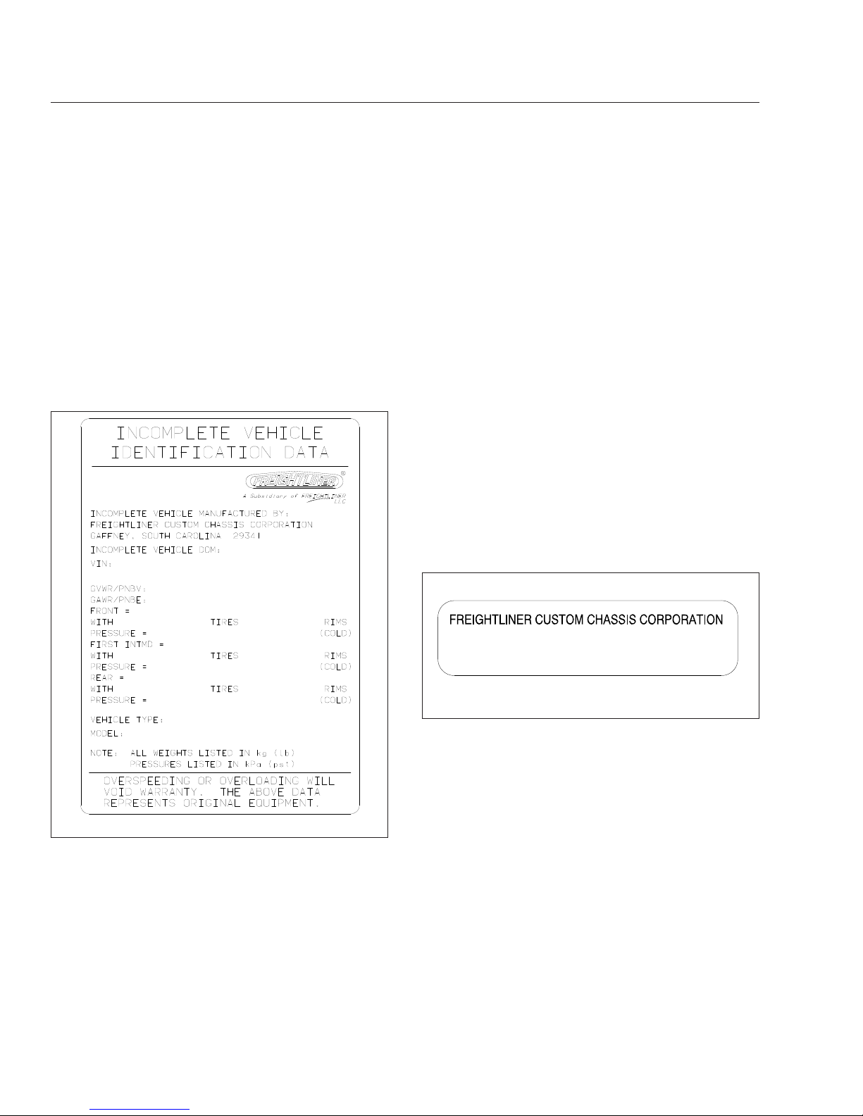
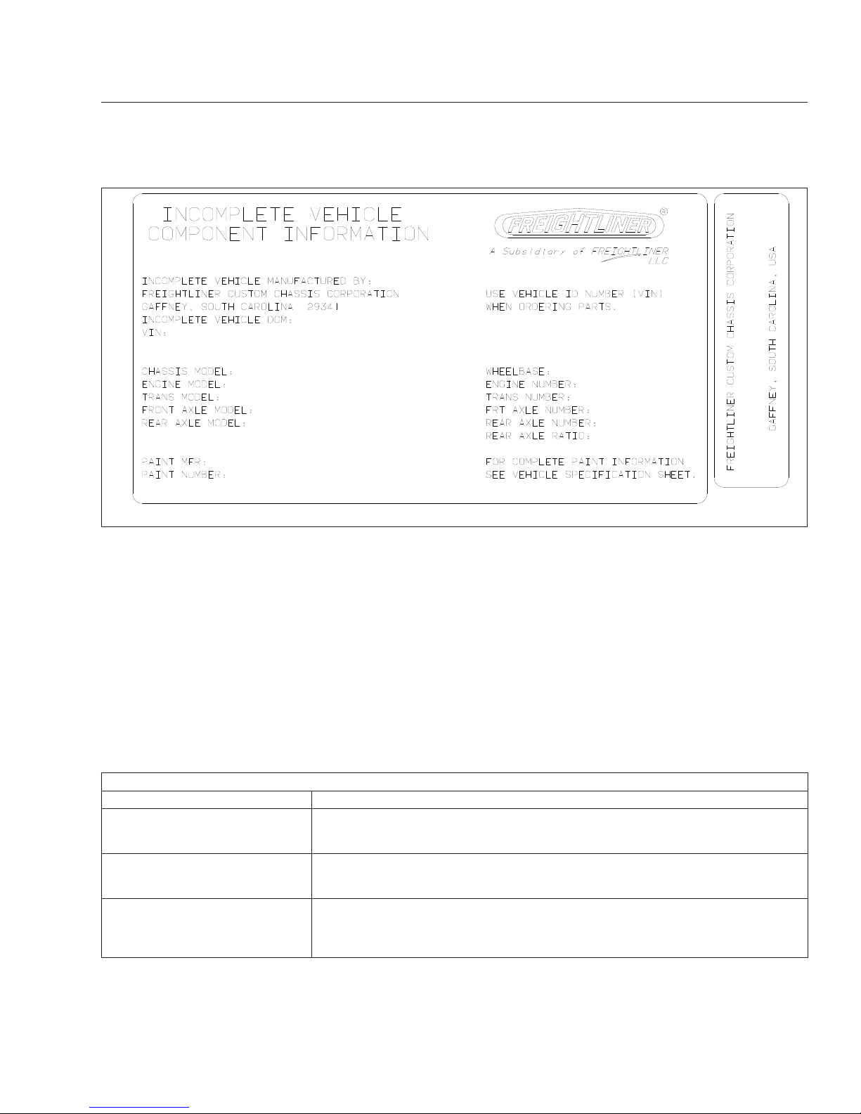
Component Information Label
NOTE: Labels shown in this chapter are examples only. Actual specifications may vary from
vehicle to vehicle.
The component information label lists the manufacturer, month and year of manufacture, vehicle identification number (VIN), gross vehicle weight rating
(GVWR), front and rear gross axle weight ratings
(GAWR), and tire and wheel information. It also indicates if the vehicle has been certified as compliant
with Federal Motor Vehicle Safety Standard
(FMVSS). See
Fig. 1.1.
The tire and rim portion of the component information
label certifies suitable tire and rim combinations that
can be installed on the vehicle for the given gross
axle weight rating. Tires and rims installed on the
vehicle at the time of manufacture may have a higher
load capacity than that certified by the tire and rim
label. If the tires and rims currently on the vehicle
have a lower load capacity than that shown on the
tire and rim label, then the tires and rims determine
the load limitations on each of the axles.
Incomplete vehicles intended for service in the U.S.
have an incomplete vehicle certification label attached by the final-stage manufacturer. This label will
be attached to the incomplete vehicle document included with the vehicle, and certifies that the vehicle
conforms to all applicable FMVSS regulations in effect on the date of completion.
Vehicle Identification Number
(VIN)
The chassis vehicle identification number is permanently attached to the chassis in the engine compartment (depending on vehicle options, usually on the
metal panel where the steering driveline enters the
engine compartment). See
Fig. 1.2. The last six dig-
its are the chassis serial number. The chassis number is stamped on the left frame rail, over the front
axle. A VIN label is also mounted by the body
builder. Mounting locations vary, to include the glove
box. See
Fig. 1.3.
NOTE: Always include the chassis serial number (last six digits of the VIN) when communicating with Daimler Trucks North America.
Emissions Labels
Aftertreatment System Indicators
Label
Engines and vehicles manufactured after December
31, 2006 and domiciled in the U.S. or Canada are
required to meet all EPA regulations effective as of
the vehicle build date, and are equipped with an
emission aftertreatment system (ATS). Vehicles domiciled outside of the U.S. and Canada may not
09/11/2002 f080123
Fig. 1.1, Component Information Label
GAFFNEY, SOUTH CAROLINA, USA
4UZA4FVC0TC748531
f080061a
04/18/2005
Fig. 1.2, Vehicle Identification Number (VIN) Label
Vehicle Identification
1.1
Page 7
have aftertreatment equipment, depending upon local
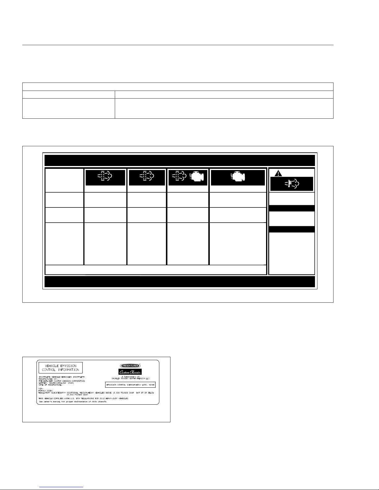
statutory emissions guidelines. See Table 1.1.
A reference label included with the driver’s documentation package contains important warning indicators
in the instrument cluster that pertain to the ATS. See
Fig. 1.4.
It is a violation of U.S. federal law to alter exhaust
plumbing, ATS, or other components in any way that
would bring the engine/vehicle out of compliance with
certification requirements [Ref: 42 U.S.C. S7522(a)
(3)]. It is the owner’s responsibility to maintain the
vehicle so that it conforms to EPA regulations.
Vehicle Emission Control Information
Label
Model year 2013 and later vehicles meet additional
requirements as specified by federal greenhouse gas
and fuel efficiency regulations (GHG14). Model year
2017 and later vehicles meet similar requirements as
specified by GHG17 requirements. These vehicles
are equipped with components that increase fuel efficiency and reduce GHG emissions. Components
may include, but are not limited to, low-rolling resistance tires.
Applicable Emissions System Based on Build Date and EPA Regulations
Build Date Regulation: Emissions Components
January 1, 2007–December 31,
2009
EPA07 (reduce nitrogen oxides (NOx) emissions to 1.1 g/bhp-hr, and reduce
particulate matter emissions to 0.01 g/bhp-hr): Aftertreatment device (ATD) containing
a diesel particulate filter that traps soot and ash.
*
January 1, 2010–December 31,
2012
EPA10 (reduce NOx emissions to 0.2 g/bhp-hr): EPA07-type ATD, with additional
selective catalyst reduction (SCR) technology that utilizes diesel exhaust fluid (DEF)
to convert NOx to nitrogen and water vapor.
From March 5, 2012–December
31, 2015
GHG14: Aerodynamic and fuel efficiency components including, but not limited to,
tires, cab/sleeper side extenders, chassis fairings, bumper, hood, vehicle speed
limiters, and idle reduction timers specifically designed to meet regulatory fuel
efficiency and greenhouse gas emissions standards.
12/04/2001
f080122
Fig. 1.3, Vehicle Identification Number Label, Typical
Vehicle Identification
1.2
Page 8
Applicable Emissions System Based on Build Date and EPA Regulations
Build Date Regulation: Emissions Components
From January 1, 2016
GHG17: GHG14 components plus OBD16 instrumentation and sensor upgrades, and
component technology that meets NHTSA and EPA 2017 fuel efficiency and
greenhouse gas emission standards (GHG17) requirements.
*
Cummins, Detroit, and Mercedes-Benz ATD’s are also equipped with a diesel oxidation catalyst to break down pollutants.
Table 1.1, Applicable Emissions System Based on Build Date and EPA Regulations
A Vehicle Emission Control Information Label indicates compliance with GHG14 regulations. See
Fig. 1.5. It is the owner’s responsibility to maintain
the vehicle so that it conforms to EPA and NHTSA
regulations.
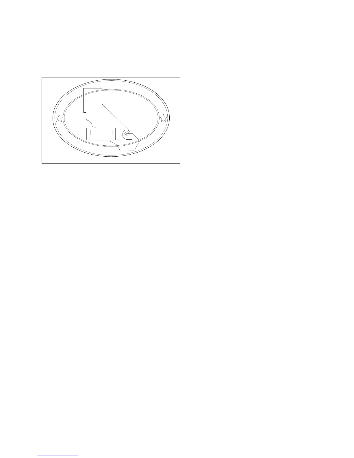
Certified Clean Idle Label
The California Air Resources Board (CARB) requires
model year 2008 and newer heavy-duty diesel engines to be equipped with a non-programmable engine shutdown system that automatically shuts down
the engine after five minutes of idling in order to limit
emissions of particulate matter and NOx.
Certified vehicles are equipped with a label placed
near the bottom edge of the driver-side door. See
Fig. 1.6.
f080156
EXHAUST AFTERTREATMENT SYSTEM INFORMATION
Switch.
Level 1 Level 3Level 2 Level 4
Filter Regeneration
Recommended.
Filter is reaching
Bring vehicle to
highway speeds to
Filter
Regeneration
Filter is now
reaching maximum
capacity
.
To avoid engine
derate, bring vehicle
Parked Regeneration
Required − Engine
Derate
Filter has reached
maximum capacity
.
Vehicle must be
parked, and a Parked
Service Regeneration Required.
Engine Derate To Idle Only.
Filter has exceeded maximum
capacity.
Vehicle must be parked, and a
Service Regeneration must be
(Solid)
(Flashing) (Flashing)
CHECK
INDICATOR
LAMP(S)
Indicator Lamp
Message(s)
Diesel Particulate
Filter Condition
Required Action
capacity
.
STOP
allow for an
Automatic
Regeneration or
perform a Parked
to highway speeds
to allow for an
Automatic
Regeneration, or
perform a Parked
Regeneration as
soon as possible.
Regeneration must
be performed.
Engine will begin
derate.
performed. Check engine
operator’s manual for details.
Engine will shut down.
For a driver performed Parked Regeneration, vehicle must be equipped with a dash mounted Regeneration Switch.
02/20/2009
W
ARNING
HEST (High Exhaust
System Temperature)
Exhaust components
and exhaust gas are at
high temperature. When
stationary, keep away
from people and
flammable materials or
vapors.
A regeneration is in
progress.
Flashing
Solid
Regeneration.
Necessary
Fig. 1.4, ATS Indicators
03/02/2012 f080183
Fig. 1.5, Vehicle Emission Control Information Label
Vehicle Identification
1.3
Page 9
CERTIFIED
CLEAN IDLE
02/20/2012 f080179
Fig. 1.6, CARB Clean Idle Label
Vehicle Identification
1.4
Page 10

2
Instruments
Ametek Instrument Panel ........................................................... 2.1
Warning and Indicator Lights ........................................................ 2.9
Speedometer and Tachometer ...................................................... 2.16
Standard Instruments ............................................................. 2.17
Optional Instruments ............................................................. 2.19
Page 11

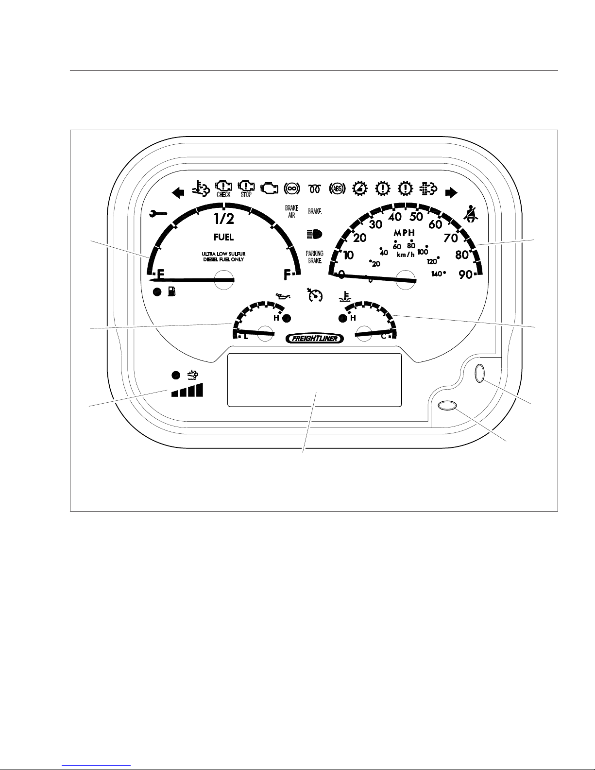
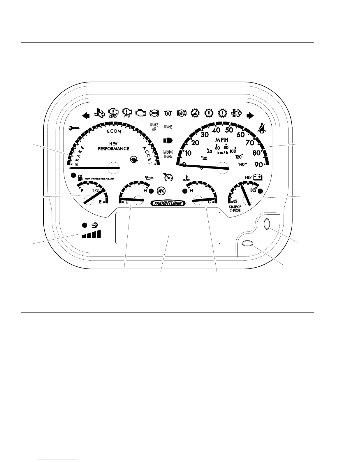
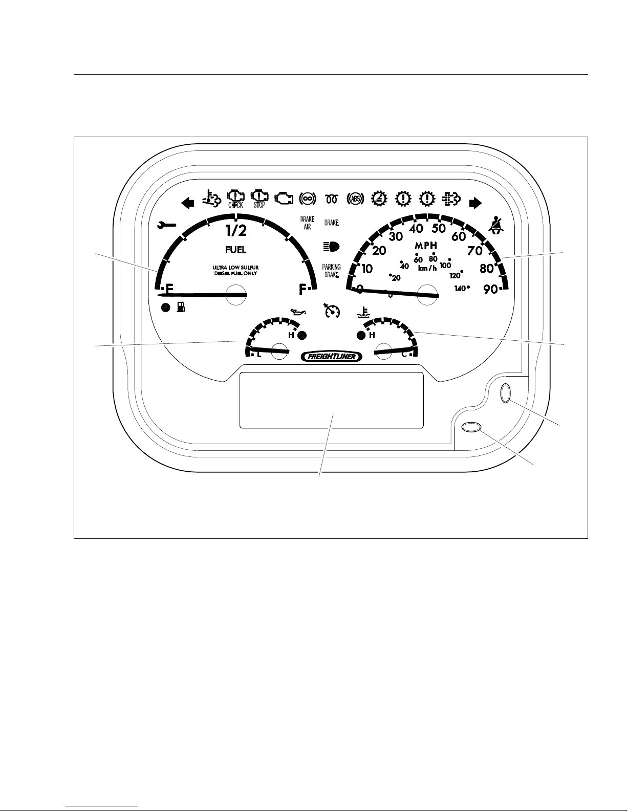
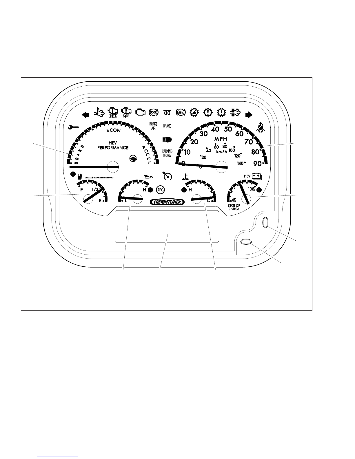
Ametek Instrument Panel
The following information describes a typical instrument panel manufactured by Ametek.
Figure 2.1 and
Fig. 2.2 show instrument panels for vehicles that are
compliant with EPA10 and newer regulations, for
both diesel and hybrid-electric vehicles (HEV).
Fig-
ure 2.3 and Fig. 2.4 show instrument panels for ve-
hicles that are EPA07-compliant for both diesel and
HEV vehicles.
NOTE: These instrument panels are shown with
a standard U.S. speedometer, which shows
miles per hour (mph) more prominently than kilometers per hour (km/h).
Message Display Center
The message display is a graphical, backlit, liquid
crystal display (LCD) that relays information to the
vehicle operator. The messages displayed include:
•
Odometer
•
Trip Odometer 1/Trip Odometer 2
•
Chassis Battery Voltage
•
Instantaneous Fuel Rate
•
Average Fuel Rate
•
Gear Attained Status
•
Transmission Temperature
•
Hour Meter
•
Boost Pressure
•
Engine Oil Pressure
•
Coolant Temperature
•
Fuel Level
•
Percent Engine Load
•
Engine RPM
During normal operation, the LCD displays the odometer value and chassis battery voltage on the top
line, and driver selected parameters, such as the trip
odometer and fuel rate, on the second and third
lines.
Priority Messages
Priority messages (including warning messages) are
displayed in the LCD due to various inputs or data
messages. Unless noted otherwise, the priority message will take over the whole screen, allowing multiple messages to be displayed in five second intervals.
Self-Test
When the ignition is turned on, a required self-test
automatically begins. Gauge needles will reset to
zero during the self-test, and then immediately move
to the position dictated by the data received. During
this time, the warning lights, alarm (buzzer), and
driver display screen will also perform a self-test.
NOTE: The driver can activate or deactivate the
start-up self-test by accessing the setup menu.
Menu System
The menu system is shown on the driver display
screen once the self-test is finished. The menu system responds to input from the driver and remains
active as long as the ignition is on. In order for the
driver to operate the menu system, the ignition must
be ON, and the park brake must be set (ON). The
main features of the menu system are described
below.
•
Setup—this is used to set various parameters,
which are saved when the ignition is turned off.
Setup has select display units, startup screen,
LCD contrast, and reset parameters.
•
Maintenance—shows various maintenance intervals such as engine oil, air filter, etc.
•
Diagnostics—this is used for setting and reading inputs and outputs and checking the
gauges. It also shows the hardware and software version of the instrument panel, and has
menus to retrieve active error codes from the
engine, transmission, and ABS controllers.
NOTE: No lines can be highlighted in the menu
system screen. To get to the sections that can
be highlighted, press the right arrow toggle button and hold it for two seconds. The display
screen will change and the options shown can
then be highlighted. Once a selection has been
chosen and changes are made, press the right
arrow toggle button to go back to the main message display screen.
Instruments
2.1
Page 12
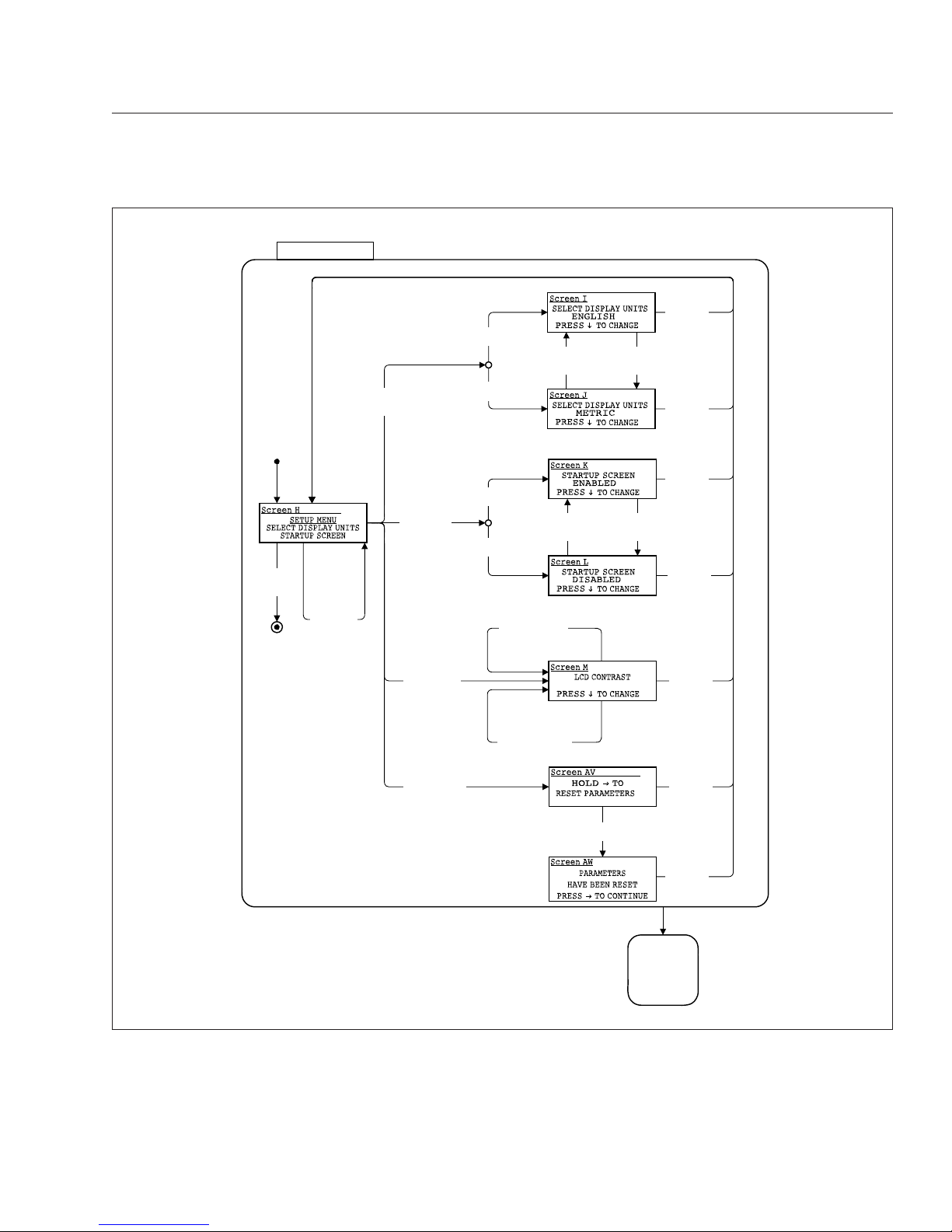
Setup Menu
Select Display Units
The set units screen allows the driver to choose between English or metric units of measurement for the
displayed values. To navigate to the set units screen,
see
Fig. 2.5, screens H, I, and J.
Startup Screen
The startup screen selection allows the driver to turn
the startup screen on or off.
LCD Contrast
Select contrast from the menu to set the LCD contrast. Use the down toggle button to set the contrast
to the desired level. To navigate to the contrast
screen, see
Fig. 2.5, screen M.
Reset Parameters
The reset parameters screen is included with vehicles that have the Allison transmission prognostics
feature.
10/13/2009 f611051
1
2
3
6
8
7
4
5
1. Fuel Gauge
2. Speedometer
3. Coolant Temperature Gauge
4. Toggle Button, Right
5. Toggle Button, Down
6. Message Display Center
7. Diesel Exhaust Fluid (DEF) Gauge
8. Engine Oil Pressure Gauge
Fig. 2.1, Typical Ametek Instrument Panel (diesel), EPA10 and Newer Engines
Instruments
2.2
Page 13
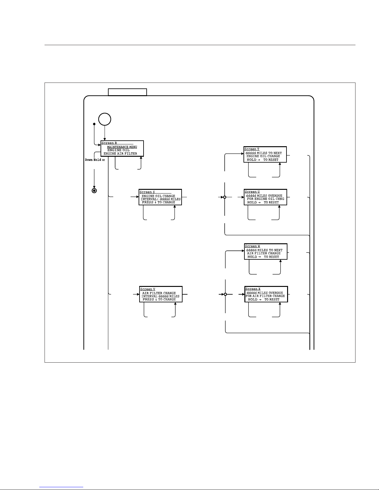
Maintenance Menu
The maintenance menu has the following three sub
menus:
•
maintenance intervals
•
transmission oil life remaining
•
transmission oil filter life monitor
Maintenance Intervals
The maintenance intervals menu allows the driver to
set the change intervals for engine oil and engine air
filter. If the intervals are set to zero, the maintenance
warnings must be disabled.
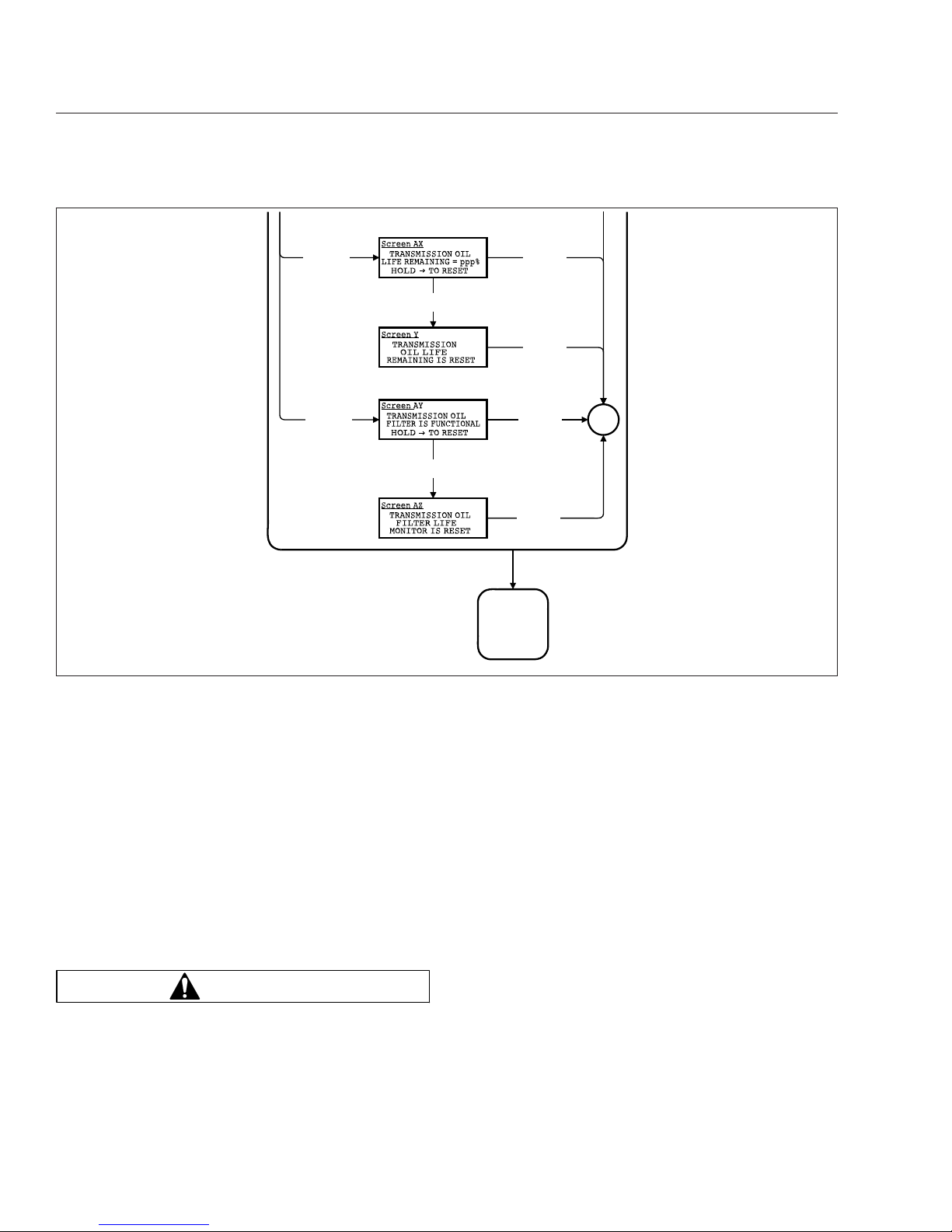
Transmission Oil Life Remaining
If transmission prognostics are enabled, this menu
indicates how much useful oil life remains.
Transmission Oil Filter Life Monitor
If transmission prognostics are enabled, the transmission oil filter life monitor tells the driver if the
transmission oil filter is clogged and in need of repair.
A message will appear on the display screen as
10/13/2009 f611053
1
2
9
3
7
10
86
4
5
1. HEV Performance Gauge
2. Speedometer
3. HEV Battery Gauge
4. Toggle Button, Right
5. Toggle Button, Down
6. Coolant Temperature Gauge
7. Message Display Center
8. Engine Oil Pressure Gauge
9. Diesel Exhaust Fluid (DEF) Gauge
10. Fuel Gauge
Fig. 2.2, Typical Ametek Instrument Panel (HEV), EPA10 and Newer Engines
Instruments
2.3
Page 14
TRANS OIL FILTER FUNCTIONAL or TRANS OIL
FILTER CLOGGED.
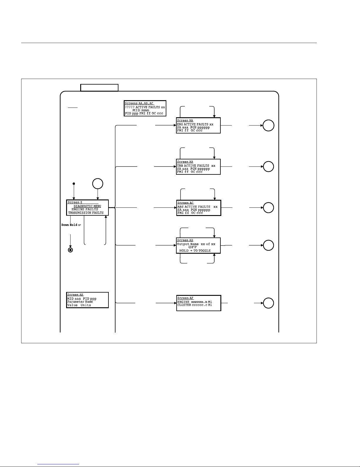
Diagnostic Menu
The diagnostic menu contains the following items:
•
engine faults
•
transmission faults
•
ABS faults
•
check outputs
•
odometer diagnostics
•
check gauges
•
check indicators (warning lamps)
•
check LCD
•
check binary inputs
•
check analog inputs
•
check datalink
•
hardware/software version
All of the items in the diagnostic menu can be accessed by using the toggle buttons and selecting the
auxiliary screens. Then navigate to the diagnostic
09/23/2009 f611049
1
2
3
6
7
4
5
1. Fuel Gauge
2. Speedometer
3. Coolant Temperature Gauge
4. Toggle Button, Right
5. Toggle Button, Down
6. Message Display Center
7. Engine Oil Pressure Gauge
Fig. 2.3, Typical Ametek Instrument Panel (diesel), EPA07-Compliant
Instruments
2.4
Page 15
sub-menu. Some of the more frequently used diagnostic menus are described further below.
Engine Faults
This screen displays engine fault codes that are received from the engine electronic control unit (ECU).
To navigate to the engine fault screen, see
Fig. 2.6,
screen AA.
Transmission Faults
This screen displays transmission fault codes that
are received from the transmission ECU. To navigate
to the transmission fault screen, see
Fig. 2.6, screen
AB.
ABS Diagnostics
This screen displays Antilock Brake System (ABS)
fault codes that are received from the ABS ECU. To
navigate to the ABS diagnostic screen, see
Fig. 2.6,
screen AC.
Check Gauges
The check gauges screen allows the driver to set
each gauge as a percentage of scale (either 0, 50, or
09/23/2009 f611050
1
2
3
7
9
86
4
5
1. HEV Performance Gauge
2. Speedometer
3. HEV Battery Gauge
4. Toggle Button, Right
5. Toggle Button, Down
6. Coolant Temperature Gauge
7. Message Display Center
8. Engine Oil Pressure Gauge
9. Fuel Gauge
Fig. 2.4, Typical Ametek Instrument Panel (HEV), EPA07-Compliant
Instruments
2.5
Page 16
100%), as shown in the LCD. To navigate to the
check gauges screen, see
Fig. 2.7, AG screens.
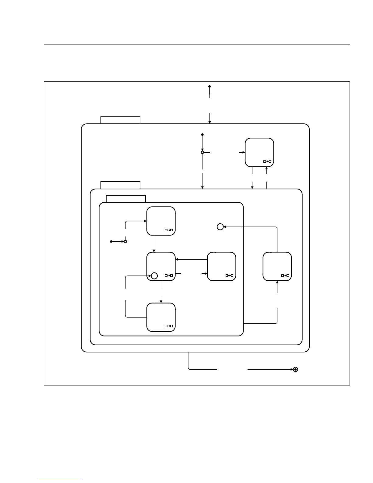
SETUP
Down Hold
Or (Right & Exit
highlighted)
Down Press
Current Units
=
Metric
Down Press
Current Units
=
English
Current Units
=
English
Current Units
=
Metric
Down Press
Startup Screen
=
Disabled
Down Press
Startup Screen
=
Enabled
Startup Screen
=
Enabled
Startup Screen
=
Disabled
Down Press
Not At Min Contrast /
Decrease Contrast
Down Press
At Min Contrast /
Set Contrast to Max
Right Press
Startup Screen
highlighted
Right Press
Select Display
Units highlighted
Right Press
Display Contrast
highlighted
Right Press
Or
Down Hold
Right Press
Or
Down Hold
Right Press
Or
Down Hold
Right Press
Or
Down Hold
Right Press
Or
Down Hold
Down Press
Highlight next
line of list.
At middle,
wrap to top
Right Hold
Reset Parameters
Right Press
Reset Parameters
highlighted
Right Press
Or
Down Hold
Right Press
Or
Down Hold
AUXILIARY
SCREENS
09/23/2009 f040792
Fig. 2.5, Setup Menu Screens
Instruments
2.6
Page 17
Warning Lamp
The warning lamp screen allows the driver to test
each warning lamp (not the vehicle load) on and then
off, displaying the lamp name and status in the LCD.
To navigate to the warning lamp screen, see
Fig. 2.7, screen AH.
Check LCD
Selecting the check LCD screen displays the Freightliner Custom Chassis Corporation (FCCC) logo in
normal and reverse video three times and then returns to the menu. To navigate to the check LCD
screen, see
Fig. 2.7, screen AI.
Diagnostics
Note 5:
Screen Z scrolls to display the
following items:
ENGINE FAULTS
TRANSMIS
SION FAULTS
ABS FAULTS
CHECK OUTPUTS
CHECK DATA INPUTS
ODOMETER DIAGNOSTICS
CHECK GAUGES
CHECK WARNING LAMPS
CHECK LCD
CHECK BINARY INPUTS
CHECK ANALOG INPUTS
CHECK DATA LINK
VERSION INFORMATION
EXIT
The text DIAGNOSTIC MENU
remains fixed on the first line.
Down Press
Display Next Fault
Down Press
Display Next Fault
Down Press
Display Next Fault
Right Press
Or
Down Hold
Down Press
Change to
Next Output
Right Press
Or
Down Hold
Right Hold
Toggle Output
State Between
Off and On
Menu
Right Press
Engine Faults
Highlighted
Right Press
Trans Faults
Highlighted
Right Press
ABS Faults
Highlighted
Right Press
Check Outputs
Highlighted
Menu
(Right & Exit
highlighted)
Menu
Right Press
Or
Down Hold
Menu
Right Press
Or
Down Hold
Menu
Screens AA,AB,AC Format For J1587
Screen AE For J1587
Down Press
Highlight next
line of list.
At bottom,
wrap to top
Right || Hold Down
Right Press
Odometer Diag
Highlighted
Menu
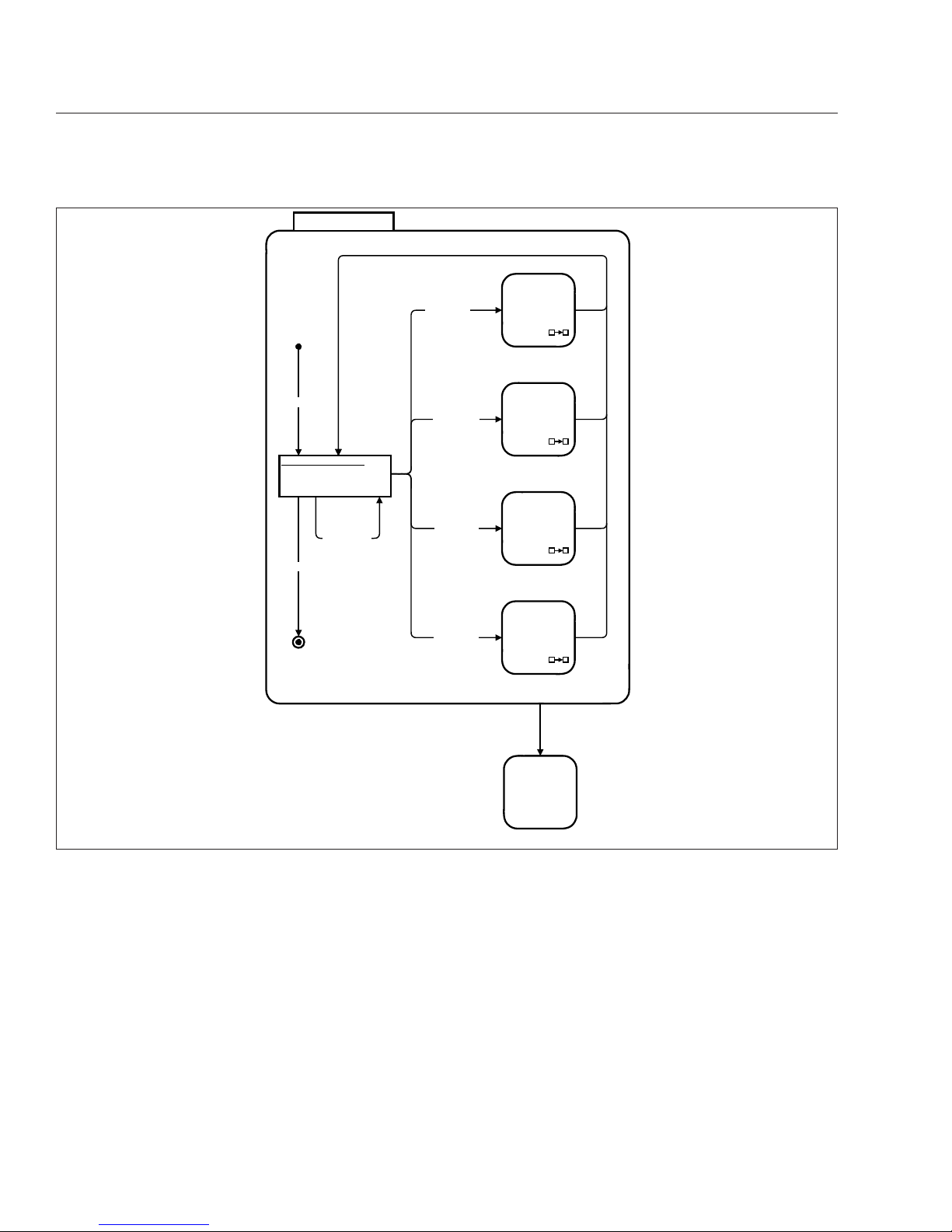
09/23/2009 f040795
Fig. 2.6, Diagnostic Menu Screens, Screen 1
Instruments
2.7
Page 18
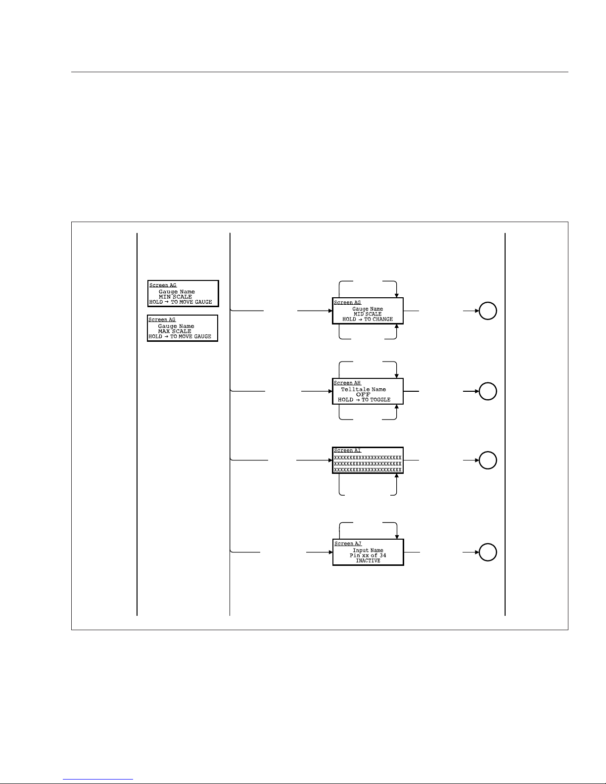
Check Binary Inputs
The check binary inputs screen displays the pin number and status of each binary input. The toggle buttons allow the driver to select each binary input. This
information is continuously updated to assist in
troubleshooting. To navigate to the check binary inputs screen, see
Fig. 2.7, screen AJ.
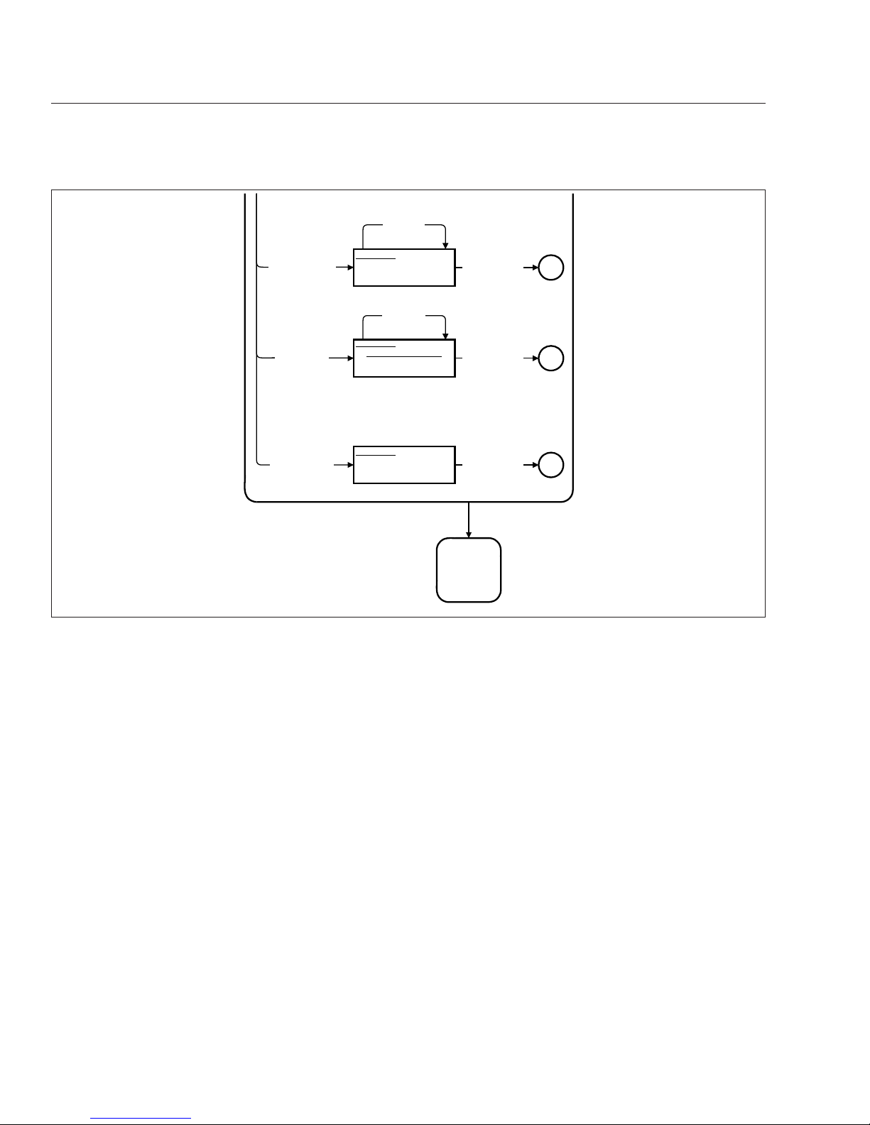
Check Analog Inputs
The check analog inputs screen displays the pin
number and actual value of each analog input defined in the system. The toggle buttons allow the
driver to select each analog input. This information is
continuously updated to assist in troubleshooting. To
navigate to the check analog input screen, see
Fig. 2.8, screen AK.
Check Datalink
The check datalink screen allows the driver to view
all devices that communicate on the J1939, J1587,
and GMLAN datalinks. To navigate to the check datalink screen, see
Fig. 2.8, screen AL.
Down Press
Change to
Next Gauge
Right Hold
Step Gauge to
Next Position
Right || Hold Down
Down Press
Change to
Next Telltale
Right Hold
Toggle State
Between
Off and On
Right || Hold Down
Every 1.5 Seconds /
Invert Video of
Displayed Image
Right ||
9 Seconds Elapsed
|| Hold Down
Down Press
Change to
Next Input
Right || Hold Down
Right Press
Check Gauges
Highlighted
Right Press
Warning Lamps
Highlighted
Right Press
Check LCD
Highlighted
Right Press
Check Binary Inputs
Highlighted
Menu
Menu
Menu
Menu
Other Text for Screen AG
09/23/2009 f040796
Fig. 2.7, Diagnostic Menu Screens, Screen 2
Instruments
2.8
Page 19
Menu Navigation
The menu navigation road maps are provided to illustrate the screens that are available in the menu
system. The paths to specific screens are shown,
along with instructions for using the toggle buttons to
move from one screen to another. Refer to the road
maps to change items shown in lines one, two, and
three of the display screen, view the setup screens,
diagnostics, etc. See
Fig. 2.5, Fig. 2.6, Fig. 2.7,
Fig. 2.8, Fig. 2.9, Fig. 2.10, Fig. 2.11, Fig. 2.12,
Fig. 2.13, Fig. 2.14, Fig. 2.15, Fig. 2.16, and
Fig. 2.17.
IMPORTANT: Follow the steps below to change
the three items (also known as favorites) shown
in the message display center. The message
display center is referred to as screen C in
Fig. 2.11.
1.
With the vehicle in park, turn the ignition to ON,
and allow the self test to complete.
2.
Press the down toggle button to select an item to
change. The selected item will now be highlighted.
3.
Press the right toggle button once to enter the
favorites display menu, shown in
Fig. 2.11,as
screen D.
4.
Use the down toggle button to scroll through the
available items.
5.
Highlight the new item, then press the right
toggle button. The selected item will now appear
in the message display center.
Warning and Indicator Lights
General Information
The warning and indicator lights are located in the
instrument panel and contain all of the standard and
optional warning and indicator lights. See Fig. 2.18
and Fig. 2.19 for diesel and HEV compliant warning
and indicator lights respectively.
02/06/2012 f040797
AUXILIARY
SCREENS
SOFTWARE VER: x.yy
CONFIG: ccccccc
HARDWARE VER: z
Right || Hold Down
Right Press
Version Information
Highlighted
Menu
Screen AM
Input Name
Pin pp of 26
xx.x Units
Down Press
Change to
Next Input
Right || Hold Down
ECUs on Data Bus
J1939 SA xx
J1939 SA yy
Down Press
Scroll Screen
Down 1 Line
Right || Hold Down
Right Press
Check Analog Inputs
Highlighted
Right Press
Check Data Link
Highlighted
Menu
Menu
Screen AK
Screen AL
Fig. 2.8, Diagnostic Menu Screens, Screen 3
Instruments
2.9
Page 20
Maintenance Warning Light
When the amber maintenance warning light illuminates, the message display center will alert the driver
as follows:
•
Oil Change Required—alerts the driver that the
engine has reached the recommended oil
change interval.
H*
SELF TEST
DISPLAY
MESSAGES
WARNING
MESSAGES
Active Warning
Messages
No Warnings Active or
All Warnings
Acknowledged
Right Hold
Park Brake On
IGNITION ON
IGNITION
OFF
Ignition
Off
Ignition On or
Headlamps On or
Marker Lamps On or
Park Brake Off
Ignition
On
Ignition Off &
Headlamps Off &
Marker Lamps Off &
Park Brake On
Self Test
Enabled
AUXILIARY
SCREENS
ACTIVE
Ignition Off &
( Headlamps On or
Marker Lamps On or
Park Brake Off )
Ignition On
USB Drive Present &
Park Brake On &
Vehicle Speed = 0 &
Not in Self Test
H*
NORMAL MODE
DOWNLOAD
MODE
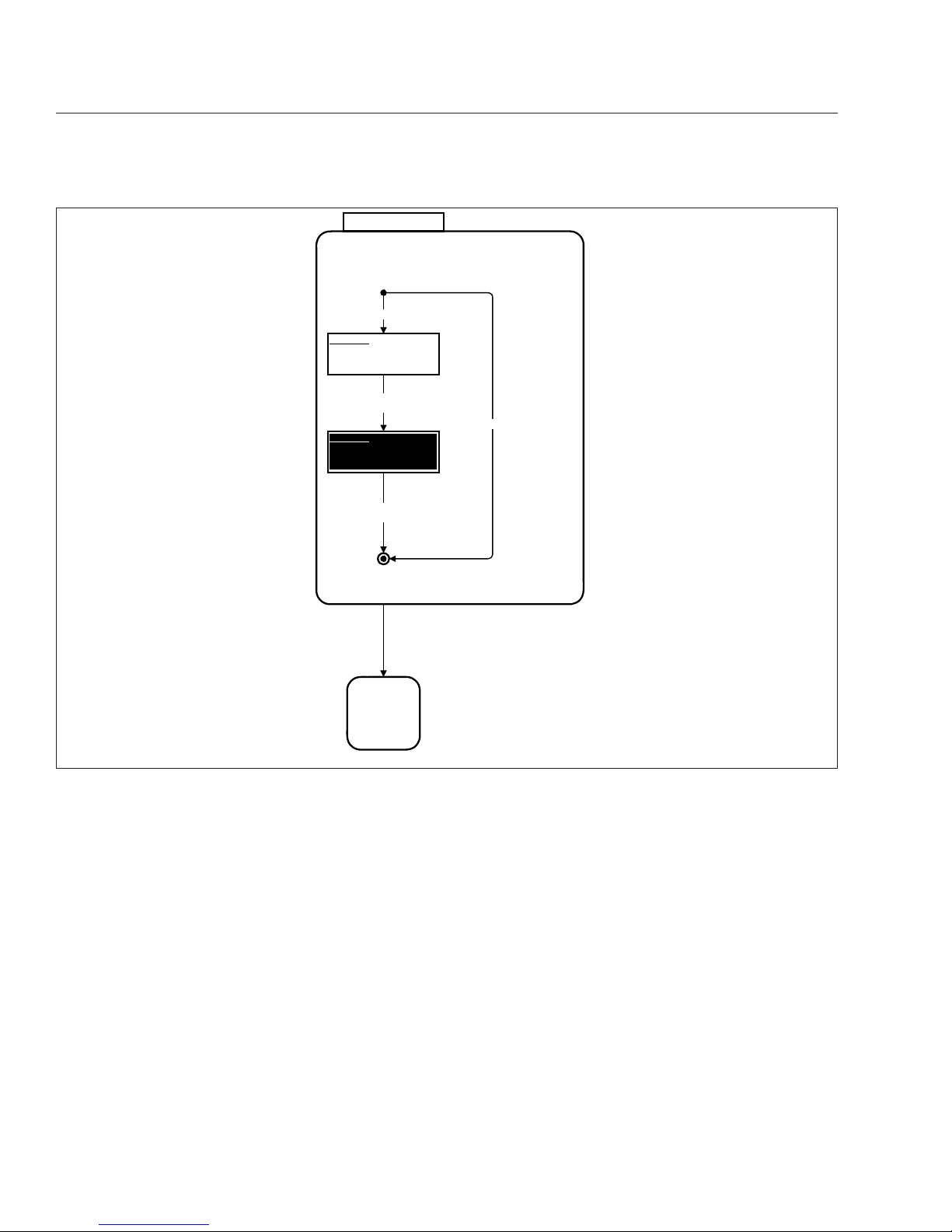
09/23/2009 f040788
Fig. 2.9, Ignition On, Normal Mode
Instruments
2.10
Page 21
•
Air Filter Reminder—the air filter requires
checking or replacement.
•
Transmission Prognostics Warning—if the
transmission has prognostics enabled.
Left-Turn Signal Arrow
The green left-turn signal arrow flashes on and off
whenever the outside left-turn signal lights are flashing. Both turn signal arrows flash when the hazard
warning flasher is on.
High Exhaust System Temperature
(HEST) Lamp
Indicates potentially hazardous exhaust temperatures
at the outlet of the tail pipe if speed is below 5 mph
(8 km/h). It does not signify the need for service; it
only alerts the vehicle operator of high exhaust temperatures. See the engine operation manual for details.
The amber HEST lamp will illuminate as follows:
•
Slow (10-second) flash, indicates a regeneration is in progress, and the driver is not controlling the engine idle speed.
•
Solid illumination indicates a regeneration is in
progress, with high exhaust temperatures at
the outlet of the tailpipe, if the speed is below
5 mph (8km/h). It does not signify the need for
service; it only alerts the vehicle operator of
high exhaust temperatures. See the engine
operator’s manual for details.
SELF TEST
DISPLAY
MESSAGES
XXXXXXXXXXXXXXXXXXXXXX
XXXXXXXXXXXXXXXXXXXXXX
XXXXXXXXXXXXXXXXXXXXXX
XXXXXXXXXXXXXXXXXXXXXX
XXXXXXXXXXXXXXXXXXXXXX
XXXXXXXXXXXXXXXXXXXXXX
Screen Displayed
for 1.5 Seconds
Screen Displayed
for 1.5 Seconds
Startup Screen Enabled
The Self Test screens display the FCCC
logo in normal video (Screen A) and in
reverse video (Screen B)
Startup Screen Disabled
Screen A
Screen B
02/06/2012 f040789
Fig. 2.10, Self Test
Instruments
2.11
Page 22
Check Engine Indicator
The amber check engine (CHECK) indicator light illuminates when the engine control unit senses a malfunction in the electronic engine control system.
Stop Engine Warning
The red stop engine (STOP) warning light illuminates
if a malfunction that could cause engine damage occurs. In most cases, the CHECK engine warning will
illuminate before the stop engine warning. When the
stop engine warning light illuminates, immediately
park the vehicle in a safe location and shut down the
engine. Continued operation with the stop engine
warning illuminated will lead to automatic engine
shutdown and possible engine damage.
Malfunction Indicator Lamp
The amber Malfunction Indicator Lamp (MIL) indicates an engine emissions-related fault. See the engine operators manual for details.
Engine Brake Light
A green engine brake light illuminates when the engine brake is applied.
Wait to Start Warning Light
The amber wait to start indicator light illuminates with
the ignition switch in the ON position prior to engine
start-up. Do not crank the engine until the wait to
start indicator light goes out.
DISPLAY MESSAGES
Selected Line 1 Data
Selected Line 2 Data
Selected Line 3 Data
Favorites Display Menu
Average Fuel Economy
Gear Attained Status
Right Press
Highlight First Item in List
Down Press
Move to, and Highlight,
Next Item in List
Right Press
Put Data For Highlighted Item
In Display Line
CurrentLine
Down Hold
Make No Changes
Down Press
Highlight
CurrentLine
HighlightTimer
= 5 sec.
WARNING
MESSAGES
AUXILIARY
SCREENS
New Warning
Message Active
Right Hold
Park Brake On
HighlightTimer
= 0
Right Hold
Reset Highlighted Item
(if resettable)
Screen C
Screen D
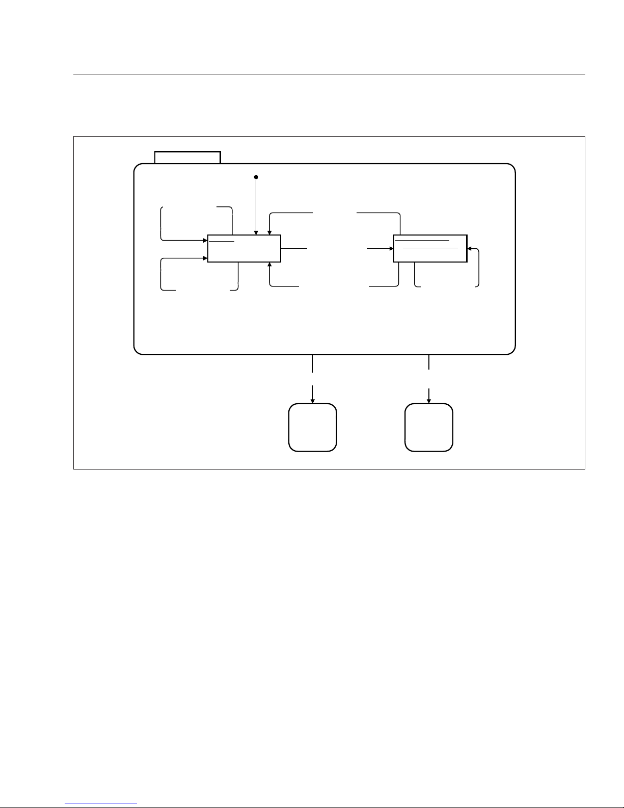
11/23/2011 f040790
Fig. 2.11, Display Messages
Instruments
2.12
Page 23
ABS Indicator
The amber ABS indicator light illuminates when there
is a malfunction in the vehicle antilock brake system
(ABS).
Shift Inhibit Indicator
On vehicles equipped with Allison 2100/2200/2500
series transmissions, the amber shift inhibit indicator
light illuminates whenever all conditions for safe
transmission shifting have not been met.
Check Transmission Indicator
The amber check transmission indicator illuminates
when the temperature of the transmission fluid goes
above the preset level set by the transmission manufacturer.
For more information, see the transmission manufacturer’s manual provided with the vehicle.
AUXILIARY SCREENS
SETUP
MAINTENANCE
DIAGNOSTICS
Down Press
Highlight next
line of list.
At middle,
wrap to top
MAINTENANCE
DIAGNOSTICS
Right Press
Setup
highlighted
Right Press
Diagnostics
highlighted
Right Press
Maintenance
highlighted
SETUP
SETUP.
DISPLAY
MESSAGES
Down Hold
TRIP DATA
Right Press
Trip Data
highlighted
Screen G
02/06/2012 f040791
Fig. 2.12, Auxiliary Screens
Instruments
2.13
Page 24
Stop Transmission (hybrid only)
The red warning light illuminates when the transmission control unit senses a malfunction.
Diesel Particulate Filter (DPF) Lamp
A solid amber illuminated DPF lamp indicates a regeneration is required. Change to a more challenging
duty cycle, such as highway driving, to raise exhaust
temperatures for at least 20 minutes, or perform a
stationary regeneration. See the engine operation
manual for details.
A blinking DPF lamp indicates that a stationary regeneration is required immediately. An engine derate
and shutdown will occur. See the instructions in the
MAINTENANCE
(Right & Exit
highlighted)
Right Press
Engine Oil
Highlighted
Right Press
Engine Air Filter
Highlighted
Down Press
Highlight next
line of list.
At middle,
wrap to top
Maint
Menu
Down Press
Display Next
Value of
Air
Change Distance
Air Change Baseline
+
Air
Change Distance
>=
Odometer
Air Change
Distance
= 0
else
Right Press
Air Change Distance
=
Current Displayed
Value
Right Hold
Air Change
Baseline
=
Odometer
Right Hold
Air Change
Baseline
=
Odometer
Right Press
Or
Down Hold
Right Press
Or
Down Hold
Down Press
Display Next
Value of
Oil
Change Distance
Oil Change Baseline
+
Oil Change Distance
>=
Odometer
else
Right Press
Oil Change Distance
=
Current Displayed
Value
Right Hold
Oil Change
Baseline
=
Odometer
Right Hold
Oil Change
Baseline
=
Odometer
Right Press
Or
Down Hold
Right Press
Or
Down Hold
Oil Change
Distance
= 0
09/23/2009 f040793
Fig. 2.13, Maintenance Menu Screens, Screen 1
Instruments
2.14
Page 25
engine manufacturer’s operator’s manual to perform
a stationary regeneration.
Right-Turn Signal Arrow
The green right-turn signal arrow flashes on and off
whenever the outside right-turn signal lights are
flashing. Both turn signal arrows flash when the hazard warning flasher is on.
Fasten Seat Belt Warning
The red fasten seat belt warning light (seat belt icon)
illuminates for 30 seconds after the ignition switch is
turned on.
WARNING
If the vehicle is equipped with an air suspension
system, do not move the vehicle with the air suspension deflated. Doing so could result in a loss
of vehicle control, possibly causing personal injury and property damage.
Air Brake Indicator
The red air brake indicator activates if the pneumatic
brake system air is low, or if the air suspension is
low.
Hydraulic Brake System Warning
The red brake system warning illuminates if there is
a hydraulic brake system failure, or if the vehicle is
powered and the engine is not running.
Headlight High-Beam Indicator
The blue high-beam indicator light illuminates when
the headlights are switched to the high-beam position.
Parking Brake On Indicator
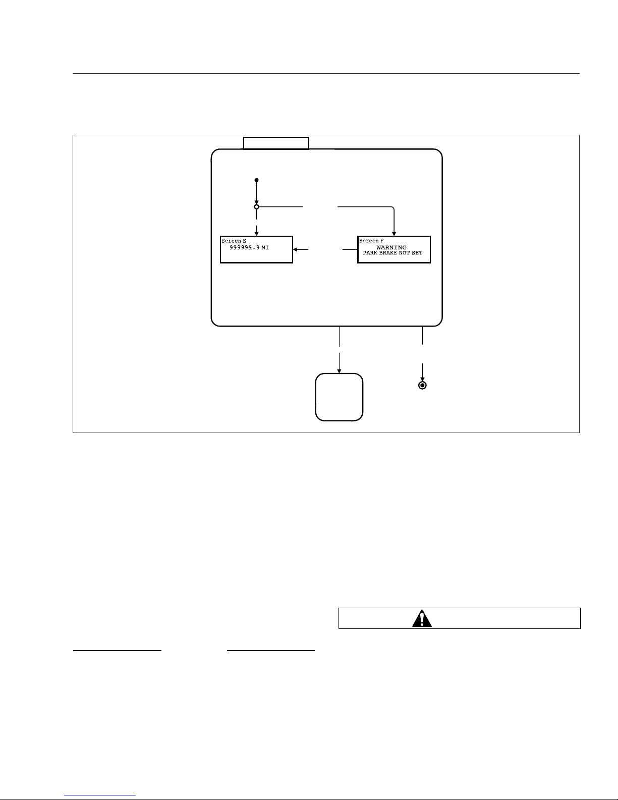
The red parking brake indicator will flash for two minutes if the parking brake is not set when the ignition
is turned off. It will also flash if the park brake is set
02/06/2012 f040794
AUXILIARY
SCREENS
Right Hold
Send SPN 1584 = 39
Right Press
Transmission
Oil Life
Highlighted
Right Press
Transmission
Oil Filter
Highlighted
Right Press
Or
Down Hold
Right Press
Or
Down Hold
Right Press
Or
Down Hold
Maint
Menu
Right Hold
Send SPN 1584 = 37
Right Press
Or
Down Hold
Fig. 2.14, Maintenance Menu Screens, Screen 2
Instruments
2.15
Page 26
and the vehicle is moving at a speed of 2 mph (3
km/h) or more. The emergency buzzer will sound
until the parking brake is released and the driver display screen will show a PARK BRAKE SET message.
Cruise Control Indicator
A green indicator illuminates when the cruise control
is activated.
Auxiliary Power Generator (hybrid
only)
A green indicator illuminates when the auxiliary
power generator is activated.
Speedometer and Tachometer
Standard speedometers are shown in Fig. 2.1,
Fig. 2.2, Fig. 2.3, and Fig. 2.4, item 2 respectively.
Optional speedometer faces are available. The
NAFTA version (not shown) of the speedometer face
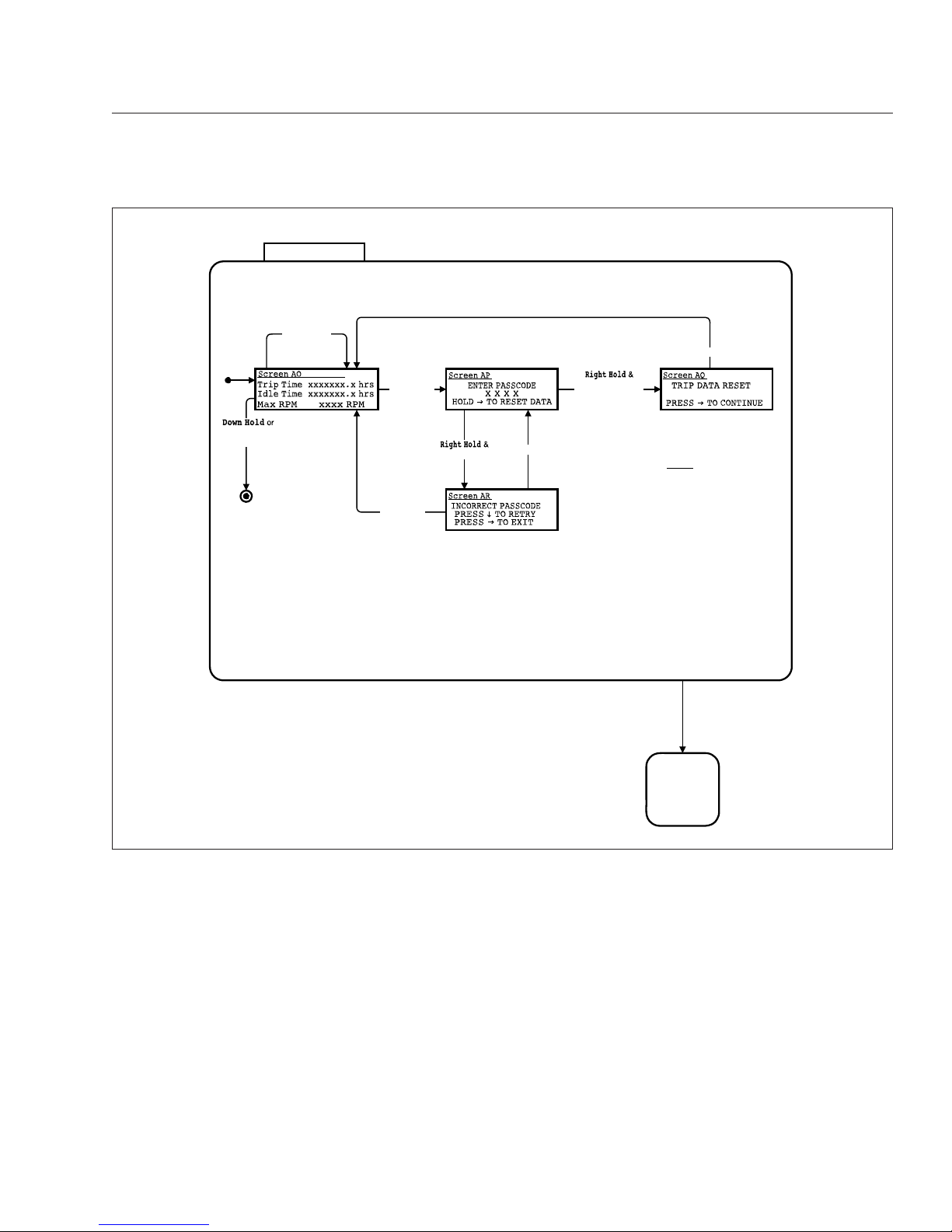
Trip Data
AUXILIARY
SCREENS
Note 6:
Screen AO scrolls to display
the following items:
Trip Time
Idle Time
Max RPM
Avg RPM
Max Speed
Avg Speed
Avg Fuel Economy
Reset All
Exit
Right Press
Reset All
Highlighted
Correct Passcode /
Reset Trip
Data
Right Press
Down Press
Highlight next
line of list.
At bottom,
wrap to top
(Right & Exit
highlighted)
Wrong Passcode /
Down Press
Right Press
09/23/2009 f040798
Fig. 2.15, Trip Data
Instruments
2.16
Page 27
reverses this arrangement, with km/h in larger numbers.
A tachometer is available as an option. See "Optional
Instruments."
Standard Instruments
Fuel Level Gauge
The fuel level gauge indicates the amount of fuel in
the fuel tank.
Low Fuel Warning Light
The low fuel warning light illuminates when the fuel
level in the fuel tank drops to a predetermined level.
When the low fuel warning light illuminates, refill the
fuel tank as soon as possible.
Engine Oil Pressure Gauge
NOTICE
A sudden decrease or absence of oil pressure
may indicate mechanical failure. Bring the vehicle
to a safe stop and investigate the cause to prevent further damage. Do not operate the engine
until the cause has been determined and corrected.
The engine oil pressure gauge is mission-critical. If
the engine oil pressure falls below preset levels, the
check engine light will illuminate. If the condition
does not improve, the CHECK engine light will also
illuminate and the buzzer will sound. At this point, the
engine will derate or shut down, depending on the
type of engine protection system installed.
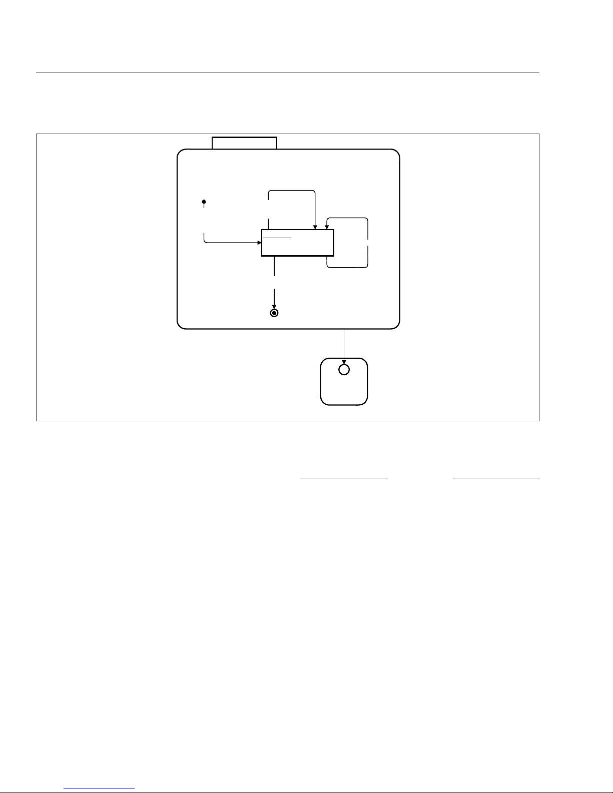
02/06/2012 f040799
WARNING MESSAGES
DISPLAY
MESSAGES
H*
WARNING
Warning Message
No Warning
Messages in List /
Msg Displayed for 5 Sec. /
Display Next Entry in
Warning Message List
Any Button Press
/
Display 1st Message
in Warning
Message List
Screen AN
Fig. 2.16, Warning Messages
Instruments
2.17
Page 28
Low Oil Pressure Warning
The low oil pressure (oil can symbol) warning light
illuminates and a buzzer sounds when the oil pressure falls below the minimum oil pressure recommended by the engine manufacturer.
High Coolant Temperature Warning
A red high coolant temperature (thermometer symbol) warning light illuminates when the engine is running and the engine coolant temperature exceeds the
maximum coolant temperature recommended by the
engine manufacturer.
Coolant Temperature Gauge
NOTICE
A sudden increase in coolant temperature may
indicate engine or cooling system failure. Bring
the vehicle to a safe stop and investigate the
cause to prevent further damage. Do not operate
the engine until the cause has been determined
and corrected.
The coolant temperature gauge is mission-critical. If
the coolant temperature rises above preset levels,
the check engine light will illuminate. If the condition
does not improve, the CHECK engine light will also
illuminate and the buzzer will sound. At this point, the
engine will derate or shut down, depending on the
type of engine protection system installed.
Primary and Secondary Air Pressure
Gauges
WARNING
If air pressure falls below minimum pressure, the
braking ability of the vehicle will be limited. Slow
the vehicle down and bring it to a gradual stop.
Do not attempt to move the vehicle until air pressure has risen above the minimum level. Moving
a vehicle without adequate braking power could
IGNITION OFF
Park Brake On
Park Brake On
Park Brake Off
IGNITION
ON
Headlamps Off &
Marker Lamps Off &
Park Brake On
Ignition On
02/06/2012 f040800
Fig. 2.17, Ignition Off (shown when ignition is keyed OFF)
Instruments
2.18
Page 29
cause an accident resulting in property damage,
personal injury, or death.
Air pressure gauges register the pressure in the primary and secondary air systems. Normal pressure
with the engine running is 100 to 120 psi (689 to 827
kPa) in both systems.
Air pressure gauges are required on all vehicles with
air brakes. A low-air-pressure warning light and
buzzer, connected to both the primary and secondary
systems, activate when air pressure in either system
drops below a minimum pressure of 65 to 75 psi
(448 to 517 kPa).
When the engine is started, the warning light and
buzzer remain on until air pressure in both systems
exceeds minimum pressure.
Optional Instruments
Air Intake Restriction Gauge
An intake-air restriction indicator, mounted in the engine compartment, measures the vacuum on the engine side of the air cleaner at the air cleaner outlet.
See
Fig. 2.20.
Air intake restriction vacuum is measured in inches
of water (inH
2
O). For vehicles equipped with a
graduated indicator or a restriction gauge on the
dash, check the gauge with the engine off. If restriction reaches 25 inH
2
O, replace the air cleaner element. Reset the indicator by pressing the button on
the bottom.
NOTE: Rain or snow can wet the filter and
cause a higher than normal reading temporarily.
09/21/2009 f611052
1
2
345678910111213
14
15
1920
17
18
16
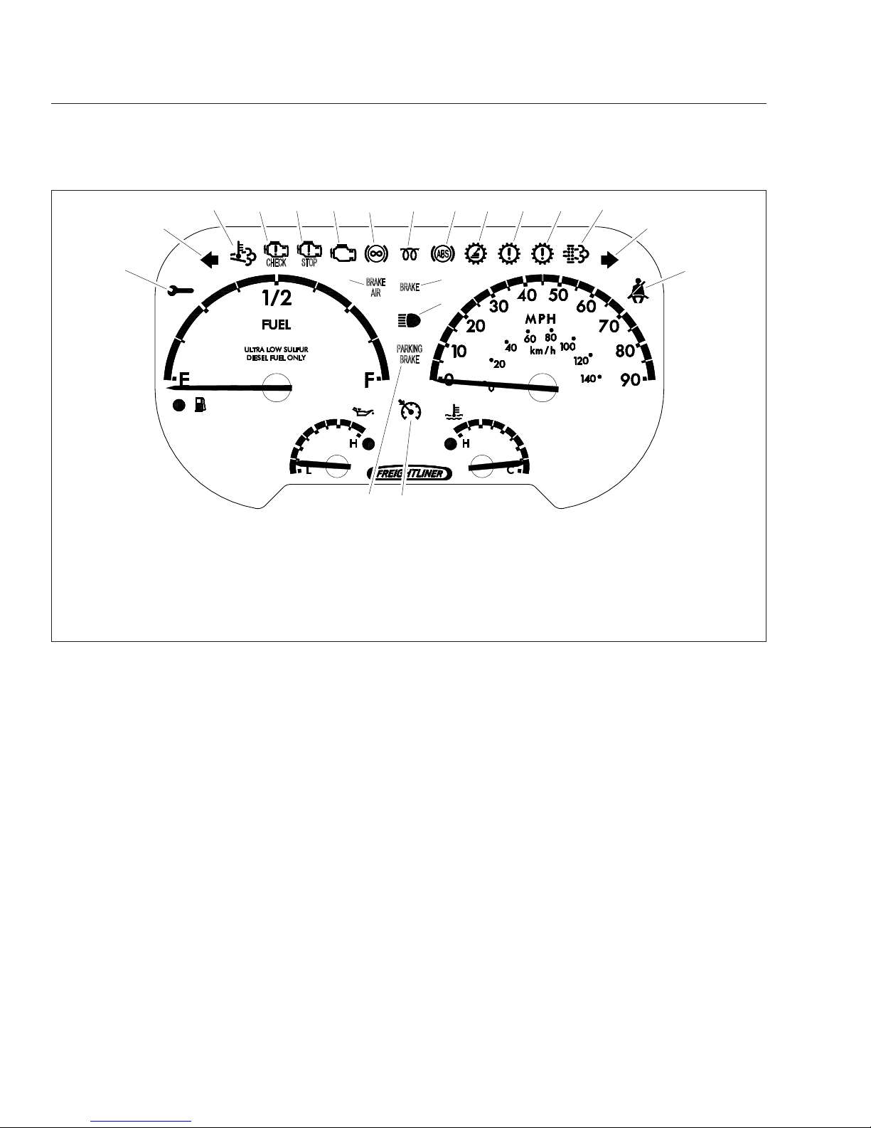
1. Maintenance Warning Light
2. Left-Turn Signal Arrow
3. High Exhaust System
Temperature (HEST) Lamp
4. Check Engine Indicator
5. Stop Engine Warning
6. Malfunction Indicator Lamp
7. Engine Brake Light
8. Wait to Start Warning Light
9. ABS Indicator
10. Shift Inhibit Indicator
11. Check Transmission Indicator
12. Stop Transmission (hybrid only)
13. Diesel Particulate Filter (DPF)
Lamp
14. Right-Turn Signal Arrow
15. Fasten Seat Belt Warning
16. Air Brake Indicator (low air
warning)
17. Hydraulic Brake System Warning
18. Headlight High-Beam Indicator
19. Cruise Control Indicator
20. Parking Brake On Indicator
Fig. 2.18, Warning Lights, Diesel
Instruments
2.19
Page 30
Single Air Pressure Gauge for
Hydraulic Brakes with Air Provision
This option is only available with hydraulic brakes
with air provision.
Transmission Fluid Temperature
Gauge
With an Allison automatic transmission, the transmission fluid temperature gauge reading should not exceed 250°F (121°C) during normal operation. If this
occurs, a warning light will activate to alert the driver.
Tachometer
A tachometer indicates engine speed in revolutions
per minute (rpm) and serves as a guide for shifting
the transmission and for keeping the engine in the
appropriate rpm range. For low idle and rated rpm,
see the engine identification plate.
09/21/2009 f611054
1
2
345678910111213
14
15
2021
17
18
16
19
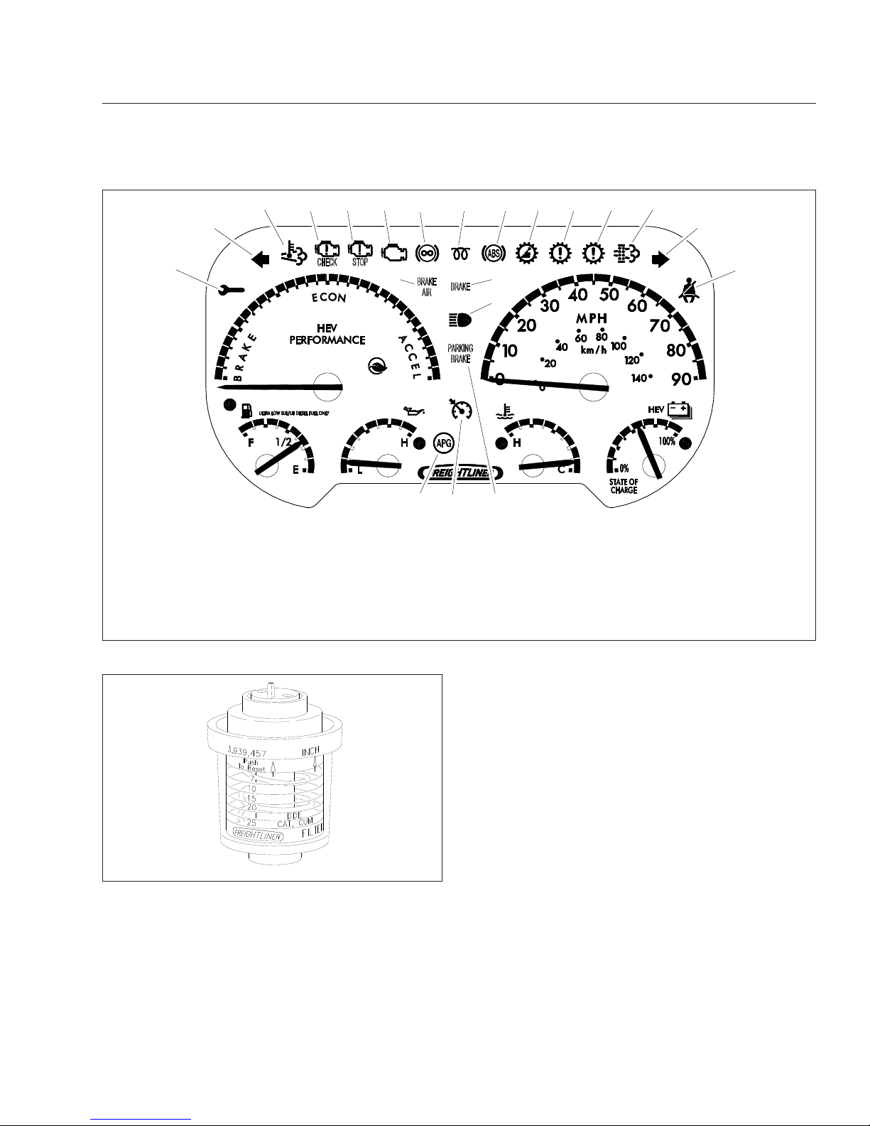
1. Maintenance Warning Light
2. Left-Turn Signal Arrow
3. High Exhaust System
Temperature (HEST) Lamp
4. Check Engine Indicator
5. Stop Engine Warning
6. Malfunction Indicator Lamp
7. Engine Brake Light
8. Wait to Start Warning Light
9. ABS Indicator
10. Shift Inhibit Indicator
11. Check Transmission Indicator
12. Stop Transmission Indicator
13. Diesel Particulate Filter (DPF)
Lamp
14. Right-Turn Signal Arrow
15. Fasten Seat Belt Warning
16. Air Brake Indicator (low air
warning)
17. Hydraulic Brake System Warning
18. Headlight High-Beam Indicator
19. Parking Brake On Indicator
20. Cruise Control Indicator
21. Auxiliary Power Generator
Fig. 2.19, Warning Lights, Hybrid Electric Vehicle
01/18/95
f600148a
Fig. 2.20, Air Intake Restriction Gauge
Instruments
2.20
Page 31

3
Controls
Ignition Switch and Key ............................................................ 3.1
Electrical System General Information ................................................ 3.1
Lighting Controls .................................................................. 3.1
Turn Signal Switch ................................................................ 3.3
Horn Controls .................................................................... 3.3
Powertrain Controls ............................................................... 3.3
Braking and Steering Controls ....................................................... 3.5
Dash-Mounted Controls ............................................................ 3.6
Page 32
Ignition Switch and Key
On most vehicles, the ignition switch can be turned
to four positions: ACCESSORY, OFF, ON, and
START. See
Fig. 3.1. An optional three-position key-
less ignition switch does not have the ACCESSORY
position.
The key can be inserted and removed only from the
OFF position. The headlights (low beams), brake
lights, fog lights, dome lights, clearance lights, turn
signals, hazard warning lights, and the parking lights
operate with the ignition switch in the OFF position,
regardless of whether the key is inserted.
Turn the key fully clockwise to the START position,
only when starting the engine. When the engine
starts, release the key. When released, the key will
rotate counterclockwise to the ON position.
In the ON position (key turned 45 degrees clockwise), all electrical systems are operable. The warning lights and the buzzer for low engine oil pressure
operate until the engine is started and minimum engine oil pressure is achieved.
Electrical System General
Information
The Walk-In Van chassis uses multiple electrical signals that are carried along a simplified set of wires,
reducing the size of wiring bundles. There are significantly fewer wires overall, meaning less chance of
damage, shorts, and other problems. The information
in this chapter is to help familiarize the driver with the
basic electrical system. Servicing the electrical system should be done only by qualified technicians.
Special skills and equipment are required. Take the
vehicle to an authorized Freightliner service facility
for repairs.
WARNING
Do not attempt to modify, add, splice, or remove
electrical wiring on this vehicle. Doing so could
damage the electrical system and result in a fire
that could cause serious personal injury or property damage.
Battery Disconnect Switch (optional)
Some Walk-In Van chassis may be equipped with a
battery disconnect switch that can be used to prevent
unwanted drain from the vehicle battery when the
vehicle is not in use or is in storage. It can also rapidly disconnect from power supplies in the event of
an emergency. Mounting locations may vary. See
Fig. 3.2.
Lighting Controls
The lighting controls mentioned under this heading
generally operate through switches located on the
dash.
07/10/96
1
2
3
4
f601179
1. Accessory (optional)
2. Off
3. On
4. Start
Fig. 3.1, Ignition Switch Positions
f545041
2
3
1
05/16/2007
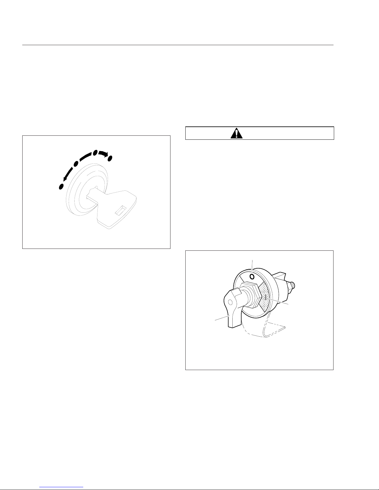
1. Power-Off Position
2. Battery Disconnected (red area)
3. Power-On Position (green area)
Fig. 3.2, Battery Disconnect Switch (optional)
Controls
3.1
Page 33

Headlight and Panel Light Controls
The control knob for the headlights, side marker
lights, taillights, parking lights, license plate lights,
and panel lights is located on the instrument panel.
See
Fig. 3.3 and Fig. 3.4. Control knob positions are
as follows:
•
All lights are off if the knob is pushed all the
way in.
•
If pulled out to the first stop, all lights are on
except the headlights.
•
If pulled all the way out, all lights including the
headlights are on.
•
Turn the knob to the right to brighten the panel
lights or turn it to the left to dim them.
•
Turn the knob all the way to the left (past the
click stop) to operate the courtesy lights.
Headlight High-Beam/Dimmer Switch
The headlight high beams are activated by pulling
the turn signal lever toward the driver. When the
headlights are on high beam, the high-beam indicator
light comes on in the instrument panel.
Hazard Warning Light Tab
The hazard warning light tab is located on the steering column under the turn signal lever. See Fig. 3.5.
Pull the tab out to turn on the hazard warning lights.
When the hazard warning light tab is pulled out, all of
the turn signal lights and both of the indicator lights
on the control panel will flash. To cancel the warning
lights, press the tab in.
An additional hazard warning light control knob may
be installed on the dash near the headlight controls.
To activate the hazard warning lights, pull this knob
out.
A
B
C
D
E
08/01/96
f601188
A. Off
B. All Lights Except Headlights
C. All Lights including Headlights
D. Panel Light Brightness
E. Courtesy Lights
Fig. 3.3, Headlight Control Knob
f601269
02/24/97
1
2
3
4
1. Windshield Wiper/Washer Control Knob
2. Headlight Control Knob
3. Cargo Light Switch
4. Cab Fan Switch
Fig. 3.4, Left-Hand Dash Panel
11/27/2007 f462122
Fig. 3.5, Hazard Warning Light Tab
Controls
3.2
Page 34

Turn Signal Switch
The turn signal switch lever is mounted on the steering column. See
Fig. 3.6. Pushing the lever down
turns on the left-turn signal lights; pulling the lever up
turns on the right-turn signal lights. When one of the
signal lights is on, a green indicator light flashes at
the left or right side of the warning and indicator light
panel. When the turn is completed, the signal will
cancel and the lever will return to the neutral position.
NOTE: The hazard warning light indicator on the
turn signal lever is to instruct the driver to pull
the hazard warning light tab that is located
under the turn signal lever.
Horn Controls
To sound the electric horn, push the horn icon on the
steering wheel. See
Fig. 3.7.
Powertrain Controls
Allison Automatic Transmissions
Allison automatic transmissions have either 6 or 7
shift positions on the selector lever. See
Fig. 3.8.
The selector lever is lighted for night driving. Electronically controlled transmissions have a pushbutton selector. See
Chapter 5 for complete trans-
mission operating instructions.
f545174
1
2
03/16/2015
1. Headlight High-Beam/Dimmer Switch
2. Hazard Warning Light Indicator
Fig. 3.6, Turn Signal Lever
f462078a
06/28/2007
1
1. Horn Pad/Icon
Fig. 3.7, Horn Control
1
P
R
N
3
D
4
09/12/2006
f261381
Fig. 3.8, T-Handle Shift Control (typical)
Controls
3.3
Page 35

Cruise Control (optional)
WARNING
Do not use the cruise control system when driving conditions do not permit maintaining a constant speed, such as heavy traffic or on roads
that are winding, icy, snow covered, slippery, or
roads with a loose driving surface. Failure to follow this precaution could cause a collision or
loss of vehicle control, possibly resulting in personal injury or property damage.
NOTE: The maximum cruise control speed allowed is 75 mph (121 km/h). However, some
vehicles may have a maximum cruise control
speed that is lower than 75 mph (121 km/h), if
the vehicle was ordered that way.
The cruise control is activated by two dash switches.
See Fig. 3.9.
•
The On/Off Switch—this two-position rocker
switch bears the legend SPD CNTL on the
lower half of the switch. When the cruise control is on, an amber light illuminates in the top
part of the switch.
•
The Set/Resume Switch—this three-position
paddle switch bears the legend RES/ACC
above the paddle and SET/CST below the
paddle.
1.
To cruise at a particular speed, do these steps:
1.1
Press the upper half of the On/Off (rocker)
switch on the instrument panel.
1.2
Hold the accelerator pedal down until the
speedometer reaches the desired speed.
1.3
Momentarily lower the paddle of the Set/
Resume switch to SET/CST.
2.
To disengage the cruise control, do these steps:
2.1
Press down the brake pedal (on automatic
or manual transmission) or
Press down the clutch pedal (on manual
transmission only)
2.2
Press the lower half of the On/Off (rocker)
switch on the instrument panel.
3.
To resume a preselected cruise speed, do these
steps:
3.1
If the On/Off (rocker) switch on the instrument panel is off, turn it on.
3.2
Momentarily raise the paddle of the Set/
Resume switch to RES/ACC. Cruise will
return to the last speed selected.
NOTE: If the ignition is shut off, the speed
memory will be lost.
4.
To adjust cruise speed up, raise the paddle of
the Set/Resume switch to RES/ACC and hold it
there until the vehicle accelerates to the new
speed, as desired.
5.
To adjust the cruise speed down, lower the
paddle of the Set/Resume switch to SET/CST
and hold it there until the vehicle decelerates to
the new speed, as desired.
NOTE: For more information about cruise control operation, see the engine manufacturer’s
service manual.
09/13/2001
1
2
f610510
To turn the cruise control on, press the upper half of the
On/Off (rocker) switch. To turn cruise control off, press
the lower half of the On/Off (rocker) switch.
1. Cruise Control On/Off (rocker) Switch
2. Cruise Control Set/Resume (paddle) Switch
Fig. 3.9, Cruise Control Switches, Dash-Mounted
Controls
3.4
Page 36

Manual Dump Valve (optional)
On vehicles equipped with a manual dump valve,
there are two ways to deflate the rear suspension.
With the key in the OFF position, toggle the dump
valve into the "lower" position. If the key is in the ON
position, the parking brake must be set (ON) before
the dump valve is toggled into the "lower" position.
NOTE: If the key is turned to the ON position
and the parking brake is not engaged, the override will cause reinflation of the air ride system.
Backup Alarm (optional)
An optional backup alarm, sounds when Reverse ®)
gear is engaged. Check the operation of the backup
alarm daily, if so equipped.
Braking and Steering Controls
Parking Brake Control
Hand-Operated Parking Brake
On all vehicles, a parking brake control lever is located to the left of the steering column. To apply the
parking brake, depress the brake pedal, then pull up
on the parking brake lever. To release the parking
brake, depress the brake pedal and push the parking
brake lever all the way down.
IMPORTANT: Take care to hold on to the parking brake lever while releasing it. Do NOT allow
the lever to slam down while releasing it.
NOTICE
Overtightening of the knob can lead to cable
breakage and/or damage to the knob and lever.
If the parking brake does not hold the vehicle securely, depress the brake pedal and release the
parking brake. Turn the knob on the end of the lever
clockwise to increase the parking brake application.
If the parking brake still doesn’t hold the vehicle securely (after adjustment), check the brake lining
thickness. For instructions, see Group 42 of the
Walk-In Van Chassis Maintenance Manual.
Hydraulic Parking Brake (optional)
To apply the hydraulic parking brake, pull the yellow
knob labeled PARKING BRAKE on the dash panel.
In order to release the hydraulic parking brake, the
engine must be running (hydraulic pressure is
needed to release the brake) and the gear selector
must be in the Neutral (N) position. To release the
parking brake, push the knob in.
CAUTION
On vehicles with hydraulic parking brakes, loss
of all hydraulic pressure will cause the parking
brake to automatically engage.
NOTE: If the gear selector is not in the Neutral
(N) position and the parking brake is on, a
buzzer will sound to let the driver know to place
the gear selector in the Neutral (N) position.
If the ignition key is in the OFF position and the
parking brake is not applied, a buzzer will sound
to let you know that you should apply the parking brake.
With the engine shut down, the hydraulic pump
will actuate with your foot on the brake pedal;
this could cause the battery to run down. If the
engine is inoperable, see the "Emergency Release of Parking Brake" procedure that follows.
Emergency Release of Parking Brake
(automatic transmission)
If your engine will not start and you want to release
the parking brake, do the following. Block the wheels
and turn the ignition switch to the ON position.
NOTICE
Do not crank the engine for more than 30 seconds at a time during any of the following procedures. Wait two minutes after each try to allow
the starter to cool. Failure to do so could cause
starter damage.
Use the ignition switch to turn the engine over several times with the gear shift selector in the Neutral
(N) position and the parking brake knob in the released (pushed) position.
NOTE: The emergency release will not work in
all cases. The system requires hydraulic fluid to
provide pressure for the procedure to work.
Since the system is pressurized when the brake
is released, the parking brake will come back on
Controls
3.5
Page 37

in 10 minutes, or longer depending on internal
pressure.
Tilt/Telescope Steering Column
Lever Adjustment (optional)
To change the position of the steering wheel, pull the
lever upward and move the steering wheel to the desired position. See Fig. 3.10. Release the lever to
lock the position. The steering wheel can be tilted up
to provide easier exit and reentry.
If the chassis is equipped with a telescoping steering
column, push the lever down and extend or retract
the steering wheel as desired.
Foot Pedal Adjustment (optional)
If the tilt/telescope steering column is equipped with
a foot pedal adjustment, depress the foot pedal to
move the steering column to the desired position.
Release the foot pedal to lock the position. See
Fig. 3.11.
Dash-Mounted Controls
Aftertreatment System (ATS) Regen
Switch
A regen switch is located on or under the dash with
which the driver can control two states. See
Fig. 3.12. These include:
•
Request regeneration
•
Default (automatic regeneration)
10/12/2007
f462115
1
1. Tilt/Telescope Lever
Fig. 3.10, Tilt/Telescope Steering Column with Lever
Adjustment
f462016
1
05/11/2005
1. Tilt/Telescope Foot Pedal
Fig. 3.11, Tilt/Telescope Steering Column with Foot
Pedal Adjustment
f610848
03/09/2012
RGEN
Fig. 3.12, ATS Regen Switch
Controls
3.6
Page 38

See the engine operation manual for details on
operation of the regen switch.
Low Idle Adjustment Switch
NOTE: The low idle adjustment switch is not
available on hydraulic hybrid units.
On some vehicles equipped with Cummins ISB engines, the engine low idle speed can be adjusted in
25 rpm increments with a low idle adjustment switch.
On these vehicles, the engine control unit is programmed to allow low idle speeds between 700 and
875 rpm.
Windshield Wiper Switch
The windshield wipers are controlled by a dashmounted knob. See
Fig. 3.4. For a single wipe cycle,
turn the knob counterclockwise. Hold it in this position until the wipers start, then release the knob. For
steady wiping at low speed, turn the knob clockwise
one position. For high-speed wiping, turn the knob
clockwise to the high-speed position.
NOTE: Heavy snow or ice can overload the
wiper motor. A circuit breaker will stop the motor
until it cools. Make sure that the windshield is
cleared of snow or ice to prevent a circuit overload.
Windshield Washer Switch
Push in and hold the windshield wiper control knob
until the desired amount of washer fluid is sprayed
on the windshield. See
Fig. 3.4. The wipers will oper-
ate on low speed until they are turned off.
Controls
3.7
Page 39

4
Engines
Engine Starting ................................................................... 4.1
Engine Operation ................................................................. 4.2
High Idle Options ................................................................. 4.3
Exhaust Aftertreatment System (ATS) ................................................. 4.3
Engine Shutdown ................................................................. 4.9
Page 40

Engine Starting
General Information
This engine chapter is to serve as a guide for best
practices only. Each make and model engine may
have operating characteristics that are unique to that
particular engine, and will be documented in the engine manufacturer’s literature. Always refer to specific
instructions and recommendations from the engine
manufacturer.
NOTE: Before starting the engine, read Chap-
ter 2
and Chapter 3 of this manual for detailed
information on how to read the instruments and
operate the controls.
Normal Starting
WARNING
Do not use any starting aid, such as ether, in engines with an air intake heater. This could cause
an explosion and serious personal injury or
death.
NOTE: Cummins engines are run on a dynamometer before being shipped from the factory.
They do not require a break-in period.
IMPORTANT: Special break-in oils are not recommended for new or rebuilt Cummins engines.
NOTICE
If a vehicle does not start on the first attempt,
make sure that the engine has completely
stopped rotating before reapplying the starter
switch. Failure to do so can cause the pinion to
release and re-engage, which could cause ring
gear and starter pinion damage.
Moving a vehicle with the starter and/or using the
starter to bump the engine for maintenance procedures is strictly prohibited. Use of these methods to bump the engine over or move the vehicle
can cause the pinion to release and re-engage,
which could cause ring gear and starter pinion
damage.
IMPORTANT: Ring gear and starter pinion damage caused by improper starting procedures is
not warrantable.
NOTICE
Do not crank the engine for more than 30 seconds at a time. Wait two minutes after each try to
allow the starter to cool. Failure to do so could
cause starter damage.
NOTICE
If the engine is equipped with a turbocharger,
protect the turbocharger during start-up by not
depressing the accelerator pedal until normal engine idle oil pressure registers on the gauge.
1.
Before engine start-up, complete the pre- and
post-trip inspections and maintenance procedures in Chapter 10.
2.
Set the parking brake.
3.
Place the transmission in neutral.
4.
Turn the key to the ON position and allow the
gauge sweep to complete. The audible alert will
sound for approximately four seconds.
During cold conditions, the WAIT TO START
lamp may illuminate. Wait until the lamp goes out
before turning the key to START.
5.
After the gauge sweep has completed, turn the
key to the START position.
NOTICE
Do not rev the engine if the oil pressure gauge
indicates no oil pressure. Shut down the engine
if oil pressure does not build within approximately ten seconds. Check to determine the
cause of the problem. Operating the engine with
no oil pressure will damage the engine.
6.
Apply load gradually during the warm-up period.
NOTICE
If the oil pressure gauge indicates no oil pressure, shut down the engine within approximately
ten seconds to avoid engine damage.
7.
Check the oil pressure gauge for any drop in lubricating oil pressure or mechanical malfunction
in the lubricating oil system. Minimum oil pressure at idle is 7 psi (50 kPa).
Engines
4.1
Page 41

Cold-Weather Starting
See the engine manufacturer’s operation manual for
starting aids that are approved for specific engines.
If the unit is equipped with a block heater, start the
block heater two to four hours before travel.
Engine Operation
Normal Operation
WARNING
Do not operate the engine in an area where flammable vapors such as gasoline or diesel fumes
are present. Shut off the engine when in an area
where flammable liquids or gases are being
handled. Failure to observe these precautions
could result in serious injury or death.
Engines produce high horsepower and peak torque
characteristics at low rpm. Because of this, it is not
necessary to operate the engine at high rpm to deliver the required horsepower at the wheels. These
characteristics may also result in less shifting and
make shifting at lower rpm (to peak torque) more
practical.
Depending on the vehicle gearing, the posted speed
limit can sometimes allow operation in either of the
top two gears. However, for improved operating efficiency (fuel economy and engine life), operate in the
top gear at reduced rpm, rather than in the next
lower gear at the maximum rpm. Cruise at partial
throttle whenever road conditions and speed requirements permit. This driving technique permits operating within the most economical power range of the
engine.
When approaching a hill, accelerate smoothly to start
the upgrade at full power (2000 rpm or higher is recommended), then shift down as desired to maintain
the optimum vehicle speed.
Engines are designed to operate over a wide speed
range. More frequent shifting than necessary does
not allow proper utilization of this flexibility. The driver
who stays in top gear and uses the wider speed
range will achieve the best fuel economy.
NOTICE
Do not allow the engine to exceed its governed
speed, or serious engine damage could result.
The engine is effective as a brake on downhill
grades, but take care not to overspeed the engine
going downhill. Use a combination of brakes and
gears to keep the vehicle under control at all times
and to keep the engine speed below the rated governed rpm.
Cold-Weather Operation
Satisfactory performance of a diesel engine operating
in low ambient temperatures requires modification of
the engine, surrounding equipment, operating practices, and maintenance procedures. The lower the
temperature, the greater the amount of modification
required. See the engine manufacturer’s operation
manual for service products approved for use in cold
weather engine operation.
If satisfactory engine temperature is not maintained,
maintenance costs will increase due to greater engine wear. If the engine coolant gets too cold, raw
fuel will wash the lubricating oil off the cylinder walls
and dilute the crankcase oil, causing all moving parts
of the engine to suffer from poor lubrication.
If the engine is in good mechanical condition and the
precautions necessary for cold-weather operation are
taken, ordinary cold weather will not cause difficulty
in starting or loss of efficiency.
The following points are important to observe when
operating in cold weather.
•
Check for cracks in the battery cases, for corrosion of the terminals, and for tightness of the
cable clamps at the terminals.
•
Charge the batteries to full capacity. Replace
damaged batteries.
•
If equipped, turn off the battery disconnect
switch after the engine is shut down to prevent
battery discharge.
•
Have the alternator output checked at an authorized Freightliner dealer.
•
Check the condition and tension of the drive
belts.
Engines
4.2
Page 42

•
Refer to the engine manufacturer’s operation
manual for recommended heaters, low-
viscosity lubricating oils, winter-grade fuels,
and approved coolants.
•
Periodically check the coolant mix ratio (con-
centration of antifreeze in the coolant). Add
more if necessary.
•
At temperatures below -4°F (-20°C), a coolant
preheater is recommended.
High Idle Options
NOTE: To operate the high idle options listed
below, the vehicle must be stopped, the transmission shift lever placed in the Neutral (N) or
Park (P) position, and the parking brake set.
IMPORTANT: Do not idle the engine for excessively long periods. The extreme heat may
cause the bearings to seize or the oil seals to
leak.
High Idle with Cruise Control
1.
Place the shift lever in Neutral (N) or Park (P)
and set the parking brake.
2.
Press the cruise switch located on the dash to
the ON position. Press the RESUME switch to
accelerate the engine revolutions per minute
(rpm) to the minimum set speed. To increase the
engine rpm, press and hold the RESUME switch.
To decrease the engine rpm, press and hold the
SET switch.
NOTE: The rpm can also be increased by depressing the throttle pedal until the desired rpm
is met, and then pressing the SET switch.
3.
Disengage the cruise control by depressing the
service brake pedal, or by moving the ON/OFF
switch to the OFF position.
Voltage-Based Auto High Idle
1.
Place the shift lever in Neutral (N) or Park (P)
and set the parking brake.
2.
The idle rpm will automatically increase when the
voltage drops below 12.2 volts for 10 seconds.
The rpm will incrementally increase every five
seconds until 13.4 volts is achieved and maintained.
3.
The Voltage-Based Auto High Idle system is disengaged by depressing the service brake pedal.
IMPORTANT: The Voltage-Based Auto High Idle
system will not return to normal operation until
one of the following occurs: The parking brake
is depressed and released, the key switch is
turned to the OFF position, or the transmission
gears are changed.
Exhaust Aftertreatment System
(ATS)
Vehicles and/or engines manufactured after December 31, 2006 and domiciled in the U.S. or Canada
are required to meet all EPA and NHTSA regulations
effective as of the vehicle build date. Engines manufactured between January 1, 2007 and December 31,
2009 meet EPA07 requirements. Engines manufactured between January 1, 2010 and December 31,
2012 meet EPA10 requirements.
Model year 2013 and later vehicles meet additional
requirements as specified by NHTSA and EPA 2014
fuel efficiency and greenhouse gas emission standards (GHG14). Model year 2017 and later vehicles
meet similar requirements as specified by GHG17
requirements. These vehicles are equipped with
components that increase fuel efficiency and reduce
GHG emissions.
IMPORTANT: Depending on local jurisdictional
guidelines, vehicles that are domiciled outside of
the U.S. and Canada may not have emissions
aftertreatment systems (ATS) that are compliant
with EPA regulations.
NOTICE
Follow these guidelines for engines that comply
with EPA07 or newer regulations, or damage may
occur to the aftertreatment device (ATD) and the
warranty may be compromised.
•
Use ultralow-sulfur diesel with 15 ppm sulfur
content or less.
•
Do not use fuel blended with used engine lube
oil or kerosene.
•
Engine lube oil must have a sulfated ash level
less than 1.0 wt %; currently referred to as
CJ-4 oil.
Engines
4.3
Page 43

IMPORTANT: Using non-specification fuels or
oils can lead to shortened diesel particulate filter
(DPF) cleaning or replacement intervals. For
example, using CJ-4+ oil with 1.3% sulfated ash
(30% more ash content) may result in the need
for DPF cleaning or replacement 20 to 30%
sooner than would normally be required.
IMPORTANT: See the engine manufacturer’s
operation manual for complete details and operation of the ATS.
EPA07 Engines
Engines built between January 1, 2007 and December 31, 2009 are required to meet EPA07 guidelines
for reduced exhaust emissions of particulate matter
and nitrogen oxides (NOx). NOx is limited to just
over 1 gram per brake horsepower hour (g/bhp-hr),
and particulate matter cannot exceed 0.01 g/bhp-hr.
The EPA07 ATS varies according to engine manufacturer and vehicle configuration, but the exhaust muffler is replaced by an aftertreatment device (ATD).
Inside the ATD, the exhaust first passes over the diesel oxidation catalyst (DOC), then passes through
the diesel particulate filter (DPF), which traps soot
particles. The soot is burned to ash during a process
called regeneration (regen).
EPA10 and Newer Engines
The EPA mandates that all engines built after December 31, 2009 must reduce the level of emissions
exhausted by the engine to the following levels:
•
Nitrogen Oxides (NOx) – 0.2 g/bhp-hr
•
Particulate Matter (PM) – .01 g/bhp-hr
To meet EPA guidelines, engines that are compliant
with EPA10 and newer regulations use an ATS that
has, in addition to a DOC/DPF device like that used
in an EPA07 ATD, a Selective Catalytic Reduction
(SCR) device to reduce NOx downstream of the engine.
After exhaust gases leave the engine, they flow into
the ATS. First they flow into a two-part ATD, comprised of a diesel oxidation catalyst (DOC), and a
diesel particulate filter (DPF). The DPF traps soot
particles, then exhaust heat converts the soot to ash
in the DPF, in a process called regeneration (regen).
The harder an engine works, the better it disposes of
soot. Passive regen occurs when the engine is run-
ning under load and regen occurs without input. If
the engine isn’t running hot enough, the electronic
controls may initiate an active regen, whereby extra
fuel is injected into the exhaust stream before the
diesel particulate filter, to superheat the soot trapped
in the filter and reduce it to ash. Both types of regen
occur without driver input.
WARNING
Active regeneration can occur automatically anytime the vehicle is moving. The exhaust gas temperature could reach 1500°F (816°C), which is hot
enough to cause a fire, heat damage to objects
or materials, or personal injury to persons near
the exhaust outlet.
The exhaust temperature can remain high even
after the vehicle has stopped. When stopping the
vehicle shortly after an automatic regen, ensure
the exhaust outlets are directed away from structures, trees, vegetation, flammable materials, and
anything else that may be damaged or injured by
exposure to high heat.
Operating at reduced engine load will allow soot to
accumulate in the DPF. When this occurs, the DPF
lamp illuminates, indicating that a regen must be performed, and the driver must either bring the vehicle
up to highway speed to increase the load, or park
the vehicle and initiate a parked regen. See Parked
Regen, later in this chapter for instructions.
After the exhaust stream passes through the ATD, it
flows through another canister housing the SCR device. A controlled quantity of diesel exhaust fluid
(DEF) is injected into the exhaust stream, where heat
converts it to ammonia (NH
3
) gas. This mixture flows
through the SCR device, where the ammonia gas
reacts with the NOx in the exhaust, to produce harmless nitrogen (N
2
) and water vapor (H2O), which then
exits out of the tailpipe.
ATS Warning Lamps
Warning lamps in the driver’s message center alert
the driver of situations with the ATS.
•
An illuminated DPF lamp indicates a regen is
needed. See Fig. 4.1.
•
A slow, 10-second flashing of the high exhaust
system temperature (HEST) lamp alerts the
driver that a parked regen is in progress, but
the exhaust temperatures are still relatively
Engines
4.4
Page 44

cool. It also indicates that the high-idle speed
is being controlled by the engine software, not
the driver. See Fig. 4.2.
•
A steadily illuminated HEST lamp alerts the
operator of high exhaust temperatures when
vehicle speed is below 5 mph (8 km/h) while it
is performing an automatic regen, and during a
parked regen.
•
An illuminated DEF warning lamp in the gauge,
indicates that the DEF tank should be refilled
at the next opportunity.
Parked Regen
DANGER
During parked regeneration, exhaust temperatures are very high, and could cause a fire, heat
damage to objects or materials, or personal injury to persons near the exhaust outlet.
Before initiating a parked regeneration, make certain the exhaust outlets are directed away from
structures, trees, vegetation, flammable materials, and anything else that may be damaged or
injured by prolonged exposure to high heat.
A reference label is included with the driver’s documentation package initially in the glove box, that explains the ATS warnings, and actions required to
avoid further engine protection sequences. See
Fig. 4.3.
The regen switch, located on the dash, is used to
initiate a parked regen of the aftertreatment device.
See
Fig. 4.4.
NOTE: The DPF lamp must be illuminated before the regen switch will initiate a parked
regen.
To initiate a parked regeneration, perform the following steps.
1.
Park the vehicle away from all combustible and
flammable materials. Chock the tires. Start and
warm the engine until the coolant temperature is
at least 150°F (66°C).
2.
Set the parking brake. If the parking brake was
already set, it must be released, then set again.
For manual transmissions, fully depress the
clutch pedal, put the transmission in neutral, then
release the pedal.
If the vehicle has a two-pedal automated transmission, shift it into gear, then back to neutral.
IMPORTANT: The driver must remain with the
vehicle during the entire regen cycle.
3.
Press and hold the regen switch for 4 seconds.
The engine will increase rpm and initiate the
regen process.
4.
The regen cycle will finish after 20 to 60 minutes,
at which time engine idle speed will drop to normal and the vehicle can be driven normally. The
HEST lamp may be illuminated, but will go out
when the vehicle speed exceeds 5 mph (8 km/h),
or the system has cooled to normal operating
temperature.
5.
To stop a parked regen at any time during the
process, engage the clutch, brake, or accelerator
pedal, or turn off the engine.
09/25/2006 f610815a
Fig. 4.1, Diesel Particulate Filter (DPF) Lamp
09/25/2006 f610816a
Fig. 4.2, High Exhaust System Temperature (HEST)
Lamp
Engines
4.5
Page 45

DPF Maintenance
Eventually ash will accumulate in the DPF and the
filter will require servicing. DPF servicing must be
performed by an authorized technician, following the
engine manufacturer’s instructions. A record must be
maintained for warranty purposes, that includes:
•
date of cleaning or replacement;
•
vehicle mileage;
•
particulate filter part number and serial number.
Diesel Exhaust Fluid and Tank,
EPA10 and Newer Engines
Diesel Exhaust Fluid
Diesel exhaust fluid (DEF) is used in the ATS to
lower NOx in the exhaust stream. DEF is colorless
and close to odorless (it may have a slightly pungent
odor similar to ammonia). It is nontoxic, nonflammable, and biodegradable. It is mildly corrosive to
aluminum, but does not affect the strength or structure of the aluminum.
White crystals may be noticeable around components that come into contact with DEF. The crystals
are easily removed with water.
DEF consumption varies depending on ambient conditions and vehicle application.
Freezing Conditions
DEF freezes to slush at around 12°F (-11°C). It is not
damaged or destroyed if frozen, and is fully usable
when thawed. The DEF in the tank is allowed to
freeze while a vehicle is non-operational. At start-up,
normal operation of the vehicle is not inhibited if the
f080147
EXHAUST AFTERTREATMENT SYSTEM INFORMATION
Switch.
Level 1 Level 3Level 2 Level 4
Filter Regeneration
Recommended
Filter is reaching
Bring vehicle to
highway speeds to
Filter Regeneration
Necessary
Filter is now
reaching maximum
capacity
.
To avoid engine
derate bring vehicle
Parked Regeneration
Required − Engine
Derate
Filter has reached
maximum capacity
.
Vehicle must be
parked and a Parked
Parked Regeneration Required −
Engine Shut Down
Filter has exceeded
maximum capacity
Vehicle must be parked and a
Parked Regeneration or Service
(Solid)
(Flashing) (Flashing)
CHECK CHECK
(Flashing)
INDICATOR
LAMP(S)
Indicator Lamp
Message(s)
Diesel Particulate
Filter Condition
Required Action
capacity
. .
STOP
See Engine Operator’s Manual for complete Regeneration Instructions.
allow for an Automatic
Regeneration or
perform a Parked
Regeneration.
to highway speeds
to allow for an
Automatic
Regeneration or
perform a Parked
Regeneration as
soon as possible.
Regeneration must
be performed −
engine will begin
derate.
Regeneration must be performed.
Check engine operator’s manual
for details −engine will shut down.
For a driver performed Parked Regeneration, vehicle must be equipped with a dash mounted Regeneration Switch.
06/29/2009
24−01583−000B
W
ARNING
HEST (High Exhaust
System Temperature)
Exhaust Components
and exhaust gas are
at high temperature.
When stationary, keep
away from people and
flammable materials
or vapors.
A regeneration is in
progress.
Flashing
Solid
Fig. 4.3, Exhaust-Aftertreatment Warnings Reference Label
f611199
06/19/2012
Fig. 4.4, Regen Switch
Engines
4.6
Page 46

DEF is frozen; an immersion heater with engine coolant flowing through it warms the DEF once the engine is running, allowing the SCR system to operate.
Pre-2013 DEF supply lines are electrically-heated
and are purged when the engine is shut down; complete purging of the DEF lines requires approximately
five minutes after the engine is shut down.
DEF supply lines with engine model year 2013 and
newer are designed to survive freezing conditions
while containing DEF, so purging is not required.
DEF Tank
Engines that are compliant with EPA10 and newer
regulations are equipped with a DEF tank located
between the ATS and the fuel tank, or an optional
location forward of the fuel tank. The DEF tank has a
19 mm filler neck inlet that prevents the hose from a
diesel outlet from being inserted, and has a blue cap
for easy identification.
The DEF tank will require filling a minimum of approximately every second diesel refuel depending on
the DEF tank capacity. The Walk-In Van uses a 10gallon tank capacity. DEF consumption is approximately 2% of fuel consumption, dependent on vehicle operation. For every 50 gallons of diesel fuel
consumed, approximately 1 gallon of DEF will be
consumed.
DEF Gauge
The DEF level is measured in a stand-alone gauge.
See Fig. 4.5.
The DEF gauge has a warning lamp that illuminates
when the DEF tank is near empty, and a DEF lightbar that indicates the level in the DEF tank as follows.
•
Four bars illuminated green—Between 75%
and 100% full
•
Three bars illuminated green—Between 50%
and 75% full
•
Two bars illuminated green—Between 25%
and 50% full
•
One bar illuminated green—Between approximately 10% and 25% full
•
One bar illuminated amber—DEF very low, refill DEF
•
One bar flashing red—DEF empty, refill DEF
DEF Warnings and Engine Limits
IMPORTANT: Ignoring the DEF warning lights
and not refilling the DEF will result in limited engine power with a speed limit of 5 mph (8 km/h)
eventually being applied. See the Cummins Operation and Maintenance Manual for further information.
A
1
BC
10/13/2009 f611055
A. Green bars—DEF level indicators.
B. One bar illuminated amber—DEF very low, refill DEF.
C. One bar flashing red—DEF empty, refill DEF.
1. Low DEF Warning Lamp
Fig. 4.5, DEF Gauge
Engines
4.7
Page 47

DEF Level Low—Initial and Critical
Warnings
When the DEF level reads low the following warnings
strongly encourage the driver to refill the DEF tank.
See
Fig. 4.6.
•
The DEF warning lamp illuminates constantly
(initial warning).
•
The DEF warning lamp flashes (critical warning).
•
DEF-level lightbar illuminates solid amber.
DEF Empty
When the DEF level reads empty, the following warnings are activated. See
Fig. 4.7.
•
One bar of the DEF-level lightbar flashes red.
•
The DEF warning lamp flashes.
•
The CHECK engine lamp illuminates.
Engine performance is limited, with progressively
harsher engine power limits applied.
The DEF tank must be filled to cancel the warning
sequence.
DEF Level Empty and Ignored
If the empty warning is ignored and the DEF is not
refilled, the red STOP engine lamp illuminates in addition to the DEF warning lamp and the CHECK engine warning lamp. See
Fig. 4.8.
If the DEF tank is not refilled, a 5 mph (8 km/h)
speed limit will be applied after the next engine shutdown, or while parked and idling.
DEF Quality or SCR Tampering
NOTICE
Once contaminated DEF has been detected in the
SCR system, the vehicle must be taken to an authorized service center to check the SCR system
for damage, and to deactivate the warning light
and engine limits.
If contaminated DEF or tampering is detected, the
DEF warning light flashes, and engine performance
is limited with progressively harsher engine power
limits applied. If the fault is not corrected, the
CHECK engine lamp illuminates, then the STOP engine lamp illuminates and a 5 mph (8 km/h) speed
limit will be applied after the next engine shutdown,
or while parked and idling. See
Fig. 4.8.
A
B
10/13/2009 f611056
A. DEF Warning Lamp (solid amber)
B. DEF-Level Lightbar (1 bar solid amber)
Fig. 4.6, DEF Level Low Initial and Critical Warnings
10/13/2009 f611057
A
B
NOTE: Engine performance is limited.
A. DEF Warning Lamp (flashing amber)
B. DEF-Level Lightbar (1 bar flashing red)
Fig. 4.7, DEF Empty Warning
A
B
11/18/2010 f611059b
B
NOTE: The STOP engine, CHECK engine, and DEF
lamps illuminate, engine power is limited, speed limit of
5 mph (8 km/h).
A. DEF Warning Lamp (flashing amber)
B. DEF-Level Lightbar (1 bar flashing red)
Fig. 4.8, DEF Empty and Ignored Warning
Engines
4.8
Page 48

Engine Shutdown
NOTICE
Except in an emergency, do not shut down the
engine when the coolant temperature is above
194°F (90°C). To do so could damage the engine.
1.
With the vehicle stopped, place the transmission
in the neutral (N) position and set the parking
brake.
2.
It is important to idle an engine for 3 to 5 minutes before shutting it down. This allows the lubricating oil and the coolant to carry heat away
from the combustion chambers, bearings, shafts,
and seals.
IMPORTANT: Long periods of idling are not
good for an engine because the combustion
chamber temperatures drop so low that the fuel
may not burn completely. This will cause carbon
to clog the piston rings and may result in stuck
valves.
3.
Do not idle the engine for excessively long periods.
4.
Turn the ignition key to the OFF position and
shut down the engine.
Engines
4.9
Page 49

5
Transmissions
Allison Automatic Transmissions ..................................................... 5.1
Page 50

Allison Automatic
Transmissions
General Information
Allison four- and five-speed automatic transmissions
have six or seven shift positions on the selector
lever. The selector lever is lighted for night driving.
Each forward shift position provides a range of forward gears that are selected automatically according
to the speed of the vehicle, engine temperature, and
throttle position. The 1000 Series, 2000 Series, and
2500 Series are fully automatic transmissions. See
the Allison website for additional information, at
www.allisontransmission.com.
Driving Precautions
The vehicle operator should use care when accelerating or downshifting on slippery road surfaces. Sudden acceleration or engine braking, caused by shifting to a lower gear range, can result in a loss of
vehicle control. This is very important on snow- or
ice-covered roads. See
Chapter 7 for information on
brake operation.
If the vehicle is stuck in sand or mud, do not attempt
to pull the vehicle out under its own power. Request
professional towing assistance.
NOTICE
Do not attempt to rock the vehicle. If rocking the
vehicle is necessary, even at low speeds, it may
cause engine overheating, axle damage, transmission damage or failure, or tire damage.
Do not coast the vehicle in neutral. Severe transmission damage may result and the vehicle will
not have the benefit of engine braking.
WARNING
To reduce the risk of personal injury, before
going down a steep or long grade, reduce speed
and downshift the transmission. Do not hold the
brake pedal down too long or too often while
going down a steep or long grade. This could
cause the brakes to overheat, reducing their effectiveness. As a result, the vehicle will not slow
down at the usual rate. Failure to take these
steps could result in loss of vehicle control.
To avoid skidding on slippery roads, do not downshift
into "1" (Low) at speeds above 20 mph (32 km/h).
On slippery surfaces, avoid quick movements of the
steering wheel. Decrease your speed and allow for
extra stopping distance required by these conditions.
Avoid driving through flooded areas unless you are
sure the water is no higher than the bottom of the
wheel rims. Drive through slowly. Allow adequate
stopping distance since wet brakes do not grip well.
After driving through water, gently apply the brakes
several times while the vehicle is moving slowly to
dry the brakes.
When driving on icy or graveled surfaces, reduce
speed. Avoid sharp turning maneuvers.
Series 1000, 2000, and 2500
Transmission Operation
WARNING
Do not leave the vehicle unattended with the engine running. If you leave the vehicle and the engine is running, the vehicle can move suddenly,
which could result in personal injury or property
damage.
1000 Series
On vehicles with Allison 1000 series transmissions,
do the following steps if you have to leave the cab
with the engine running (for example, when checking
the transmission fluid):
Without Park (P) Position
1.
Bring the vehicle to a complete stop using the
service brake.
2.
Ensure that the engine is at low idle rpm.
3.
Put the transmission in Neutral (N).
4.
Apply the parking brake, and make sure it is
properly engaged.
5.
Chock the rear tires and take any other steps
necessary to keep the vehicle from moving.
With Park (P) Position
1.
Bring the vehicle to a complete stop using the
service brake.
2.
Ensure that the engine is at low idle rpm.
Transmissions
5.1
Page 51

3.
Put the transmission in Park (P).
4.
Apply the parking brake and make sure that it is
properly engaged.
5.
Engage the Park (P) range by slowly releasing
the service brake.
6.
Chock the rear tires and take any other steps
necessary to keep the vehicle from moving.
2000 Series
On vehicles with Allison 2000 series transmissions,
do the following steps if you have to leave the cab
with the engine running (for example, when checking
the transmission fluid):
Without Auto-Apply Parking Brake (PB)
Follow the instructions for vehicles with 1000 series
transmissions, under the heading "Without Park (P)
Position."
With Auto-Apply Parking Brake (PB)
1.
Bring the vehicle to a complete stop using the
service brake.
2.
Ensure that the engine is at low idle rpm.
3.
Put the transmission in Auto-Apply Parking Brake
(PB).
4.
Ensure that the parking brake is properly engaged.
5.
Chock the rear tires and take any other steps
necessary to keep the vehicle from moving.
2500 Series
On vehicles with 2500 series transmissions, instructions are as follows.
1.
Bring the vehicle to a complete stop using the
service brake.
2.
Ensure that the engine is at low idle rpm.
3.
Put the transmission in Park (P).
4.
Apply the parking brake and make sure that it is
properly engaged.
5.
Engage the Park (P) range by slowly releasing
the service brake.
6.
Chock the rear tires and take any other steps
necessary to keep the vehicle from moving.
Range Inhibit Indicator, 2000 Series
A RANGE INHIBIT indicator is a standard feature of
the 2000 series transmissions. The RANGE INHIBIT
indicator comes on to alert the driver that transmission operation is being inhibited and that the range
shifts being requested by the driver may not occur.
When certain operating conditions are detected by
the TCM (transmission control module), the controls
will lock the transmission in the current operating
range.
Shift inhibits occur under the following conditions:
•
Shifts from Neutral (N) to Reverse (R) or from
Neutral (N) to a forward range when the engine is above idle, greater than 900 rpm.
•
Forward/Reverse (R) directional shifts are typically not permitted if appreciable output shaft
speed is detected.
•
When some types of unusual transmission operating conditions are detected by the TCM,
the TCM temporarily limits transmission operation until the vehicle can be driven to a service
location. When this type of situation is detected, the TCM will lock the transmission in a
safe gear range.
Operating Instructions, On-Highway
Transmissions
Allison 1000/2000/2500 automatic transmissions are
electronically controlled and provide five or six forward ranges and one Reverse (R) range. Typically, a
T-handle shift control is used by the driver to select
the ranges. See
Fig. 5.1 and Fig. 5.2.
Park (P) [optional on 1000 and 2500
Series]
Use Park (P) when starting or shutting down the engine, to check vehicle accessories, and to operate
the engine in idle for longer than 5 minutes. This position places the transmission in Neutral (N) and engages the park pawl.
Auto-Apply Parking Brake (PB) [optional
on 2000 Series]
The Auto-Apply Parking Brake (PB) places the vehicle in Neutral (N) and applies the parking brake.
Transmissions
5.2
Page 52

Reverse (R)
Reverse (R) is used to back the vehicle. When the
selector is in Reverse (R), the reverse warning signal
will sound. Always bring the vehicle to a complete
stop before shifting from a forward range to Reverse
(R), or from Reverse (R) to a forward range.
NOTICE
Extended idling in Reverse (R) may cause transmission overheating and damage.
Do not idle in Reverse (R) for more than 5 minutes.
Select Park (P), Auto-Apply Parking Brake (PB), or
Neutral (N) when time at idle exceeds 5 minutes.
NOTE: The shift into Reverse (R) may not succeed if a range inhibitor is active. Check for illumination of the RANGE INHIBIT indicator.
Neutral (N)
The Neutral (N) position places the transmission in
Neutral (N). This position is used when starting the
engine and for stationary operation.
WARNING
Failure to apply the vehicle parking brakes when
the transmission is in neutral may allow the vehicle to move unexpectedly, possibly causing
property damage or personal injury.
When Neutral (N) is selected, the vehicle service
brakes, or parking brake must be applied. Selecting
Neutral (N) does not apply vehicle brakes unless an
auxiliary system to apply the parking brake is installed.
WARNING
Do not coast in neutral. Coasting in neutral can
cause an accident, possibly resulting in severe
personal injury or death.
Do not let the vehicle coast in Neutral (N). If the vehicle is allowed to coast in Neutral (N), you could
lose control of the vehicle.
1
P
R
N
3
D
4
09/12/2006
f261381
Fig. 5.1, T-Handle Shift Control (typical shifter)
07/23/2014 f611243
Fig. 5.2, T-Handle Shift Control (optional shifter)
Transmissions
5.3
Page 53

NOTICE
Coasting in Neutral (N) can cause severe transmission damage.
Drive (D)
WARNING
When going downhill, use a combination of
downshifting, braking, and other retarding devices to control vehicle speed and the engine’s
rated governed speed. Failure to do so could reduce vehicle braking, possibly causing loss of
vehicle control and resulting in personal injury or
property damage.
In the Drive (D) position, the transmission will initially
go into First (1) range when Drive (D) is selected. As
vehicle speed increases, the transmission will upshift
automatically through each available range up to
Fourth (4) range or Fifth (5) range. As the vehicle
slows, the transmission will downshift automatically.
When going downhill, downshift to a lower transmission range to increase engine braking and to help
maintain control. The transmission has a feature to
prevent automatic upshifting above the lower range
selected. However, during downhill operation, the
transmission may upshift to the next higher range, if
the engine is exceeding its governed speed in the
lower range.
NOTICE
Do not idle in Drive (D) for more than 5 minutes.
Extended idling in Drive (D) may cause transmission overheating and damage. Always select
Auto-Apply Parking Brake (PB) or Park (P) if time
at idle is longer than 5 minutes.
NOTE: The shift into Drive (D) may not succeed
if a range inhibitor is active. Check for illumination of the RANGE INHIBIT indicator.
Fourth and Third Ranges (4 and 3)
[optional]
Use the Fourth (4) or Third (3) range for city traffic
and for braking on steep downgrades.
Third and Second Ranges (3 and 2)
[standard]
Use the Third (3) or Second (2) range for heavy city
traffic and for braking on steeper downgrades.
First Range (1)
Use First (1) range when pulling through mud or
deep snow, when maneuvering in tight spaces, or
when driving up or down very steep grades. First (1)
range provides the vehicle with its maximum driving
torque and maximum engine braking effect.
Transmissions
5.4
Page 54

6
Steering System
Steering General Information ........................................................ 6.1
Power Steering System ............................................................ 6.1
Tilt/Telescope Steering Column ..................................................... 6.1
Page 55

Steering General Information
When there is no load on the vehicle and the front
tires are pointed straight ahead, the steering wheel
spokes should be at the 9 o’clock and 3 o’clock positions, or within 10 degrees to either side. See
Fig. 6.1. See Group 46 of the Walk-In Van Chassis
Workshop Manualfor steering adjustment procedures.
Power Steering System
The power steering system consists of a steering
gear (which includes a manual steering mechanism,
a hydraulic control valve, and a hydraulic power cylinder), hydraulic hoses, power steering pump, reservoir, and other components. The power steering
pump, driven by the engine, provides the power assist for the steering system. If the engine is not running, there is no power assist.
If the power-assist feature does not work due to hydraulic fluid loss, steering pump damage, or some
other cause, bring the vehicle to a safe stop. Do not
drive the vehicle until the cause of the problem has
been corrected.
WARNING
Driving the vehicle without the power-assist feature of the steering system requires much greater
effort, especially in sharp turns or at low speeds,
which could result in an accident and possible
injury.
Drivers should use the power available with a power
steering system carefully. If the front tires become
lodged in a deep chuckhole or rut, drive the vehicle
out instead of using the steering system to lift the
tires from the hole. Also avoid turning the tires when
they are against a curb as this places a heavy load
on steering components and could damage them.
Tilt/Telescope Steering Column
Lever Adjustment (optional)
To change the position of the steering wheel, pull the
lever upward and move the steering wheel to the desired position. See
Fig. 6.2. Release the lever to lock
the position. The steering wheel can also be tilted up
to provide easier exit and reentry.
If the chassis is equipped with a telescoping steering
column, push the lever down and extend or retract
the steering wheel as desired.
WARNING
Make sure that the control lever is in the locked
(neutral) position before driving the vehicle.
Never tilt the column while driving the vehicle.
Doing so could cause loss of vehicle control and
result in personal injury and property damage.
f461923
11/14/2001
1
2
10°
10°
10°
10°
1. 9 o’Clock 2. 3 o’Clock
Fig. 6.1, Steering Wheel Centered
10/12/2007
f462115
1
1. Tilt/Telescope Lever
Fig. 6.2, Tilt/Telescope Steering Column with Lever
Adjustment
Steering System
6.1
Page 56

Foot Pedal Adjustment (optional)
If the tilt/telescope steering column is equipped with
a foot pedal adjustment, depress the foot pedal to
move the steering column to the desired position.
Release the foot pedal to lock the position. See
Fig. 6.3.
WARNING
Make sure that the steering column is locked before driving the vehicle. Never tilt or telescope
the steering wheel while driving the vehicle.
Doing so could cause loss of vehicle control,
personal injury, and property damage.
f462016
1
05/11/2005
1. Tilt/Telescope Foot Pedal
Fig. 6.3, Tilt/Telescope Steering Column with Foot
Pedal Adjustment
Steering System
6.2
Page 57

7
Hydraulic and Air Brake
Systems
Hydraulic Brake System ............................................................ 7.1
Air Brake System ................................................................. 7.2
Page 58

Hydraulic Brake System
General Information
The hydraulic brake system includes a power
booster, master cylinder, reservoir, hydraulic brake
lines, a brake rotor on each wheel hub, and a brake
caliper and pad assembly at each rotor. See
Fig. 7.1.
IMPORTANT: Make sure that the fluid in the
master cylinder reservoirs is up to the level of
the ridge that surrounds the reservoir. Use only
heavy-duty brake fluid, DOT 3, in the hydraulic
brake system.
The master cylinder controls braking power to the
front and rear brakes. The Bendix Hydro-Max®
power booster is attached to the rear of the master
cylinder and is connected to the power steering system (which provides pressurized power steering
fluid). An electrically powered "reserve" pump operates if there is inadequate fluid flow from the power
steering pump to the power booster. The brake system warning light comes on if there is a problem
within the system. Bring the vehicle to a safe stop
and correct the problem before continuing operation
of the vehicle. See Group 42 of the Walk-In Van
Chassis Workshop Manual for hydraulic brake system troubleshooting and adjustment procedures.
Operation
Before driving the vehicle, secure all loose items in
the cab so that they will not fly forward during a full
brake application. Check that the brake system warning light is off after releasing the hand brake. If the
warning light does not go off, correct the problem
before continuing operation of the vehicle.
During normal braking stops, depress the foot brake
control pedal until braking action slows down the vehicle. Increase or decrease the pressure on the
pedal so that the vehicle comes to a smooth, safe
stop. When the forward speed of the vehicle has decreased to almost the idling speed of the engine,
push the clutch pedal in (if equipped) and shift the
transmission into Neutral (N). Apply the hand parking
brake if the vehicle is to be parked.
Meritor WABCO® Antilock Braking
System (ABS)
The Meritor WABCO® Antilock Braking System
(ABS) is an electronic wheel speed monitoring and
control system that works with the hydraulic brake
system. ABS passively monitors vehicle wheel speed
at all times, but controlswheel speed during an emergency or reduced-traction stop. In normal braking
applications, the standard hydraulic brake system is
in effect.
IMPORTANT: For proper ABS system operation,
the front and rear tires must rotate at speeds
within 16% of one another. Installing different
sized tires on just the front or rear axle will result in inaccurate wheel speed signals to the
ECU resulting in a reduced braking force, which
could lead to longer stopping distances.
ABS includes signal-generating tone wheels and sensors located in the wheel hubs of each sensed axle.
The sensors transmit vehicle wheel speed information to an electronic control unit (located on the
frame rail) that interprets these signals to calculate
wheel speed and a vehicle reference speed. If the
calculations indicate wheel lockup, the appropriate
control circuit signals the brake pressure modulator
to increase or decrease braking pressure until wheel
slip has been corrected.
The electronic control unit also has a safety circuit
that constantly monitors the wheel sensors, brake
pressure modulator, and the electrical circuitry. The
dash warning light (ABS) comes on after the ignition
04/26/2012
f460513a
A
B
A. Open caps and check fluid level.
B. Fill to this level.
Fig. 7.1, Hydraulic Brake Reservoir (MT-45 and MT-55)
Hydraulic and Air Brake Systems
7.1
Page 59

is switched to the ON position. Once the vehicle
moves faster than about 4 mph (6 km/h), the warning
light goes out only if all of the vehicle’s ABS components are working properly.
If during vehicle operation, the safety circuit senses a
failure in any part of the ABS system (a sensor,
brake pressure modulator, wiring connection, short
circuit, etc.), the warning light (ABS) comes on and
the control circuit where the failure occurred is
switched to normal braking action. Even if the ABS
system is partially or completely inoperative, normal
braking ability is maintained. An exception would be
if the brake pressure modulator or hydraulic fluid line
is damaged. Since these components are an integral
part of the hydraulic brake system, normal braking
may be impaired or inoperative.
IMPORTANT: If the ABS warning light does not
work as described above or comes on while
driving, repair the ABS system immediately to
ensure full antilock braking capability.
See the diagnostic menu screens in Chapter 2, and
follow the steps to read the fault codes in the instrument panel diagnostic menu.
During emergency or reduced-traction stops, fully
depress the brake pedal until the vehicle comes to a
safe stop; do not pump the brake pedal. With the
brake pedal fully depressed, the ABS system will
control all wheels to provide steering control and a
reduced braking distance.
WARNING
Although the ABS system improves vehicle control during emergency braking situations, the
driver still has the responsibility to change driving styles depending on existing traffic and road
conditions. Failure to change driving styles to
accomodate existing traffic and road conditions
could cause an accident, possibly resulting in
personal injury or death, or property damage.
Air Brake System
General Information
A dual air brake system consists of two independent
air brake systems that use a single set of brake controls. Each system has its own reservoir, plumbing,
and brake chambers. The primary system operates
the service brakes on the rear axle; the secondary
system operates the service brakes on the front axle.
WARNING
Do not operate the vehicle with the front brakes
backed off or disconnected. Backing off or disconnecting the front brakes will not improve vehicle handling and may lead to loss of vehicle
control resulting in property damage or personal
injury.
Before driving your vehicle, allow time for the air
compressor to build up a minimum of 95 psi (655
kPa) pressure in both the primary and the secondary
systems. Monitor the air pressure system by observing the dual system air pressure gauges and the low
air-pressure warning light and buzzer. The warning
light and buzzer shut off when the pressure in both
systems reaches 65 to 73 psi (448 to 503 kPa).
The warning light and buzzer comes on if air pressure drops below 65 to 73 psi (448 to 503 kPa) in
either system. If this happens, check the air system
pressure gauges to determine which system has low
air pressure. Although the vehicle’s speed can be
reduced using the foot brake control pedal, either the
front or the rear service brakes will not be operating,
causing a longer stopping distance. Bring the vehicle
to a safe stop and have the air system repaired before continuing.
The parking brake will apply when air pressure drops
below 38 to 42 psi (262 to 290 kPa). Do not wait for
the brake to apply automatically; when the warning
light and buzzer first come on, immediately bring the
vehicle to a safe stop. Before continuing operation of
the vehicle, correct the cause of the air loss.
Air Brake System With External Fill
(Shrader) Valve
If your engine will not start and it is desirable to release the parking brake, do the following: Block the
wheels. Turn the ignition switch to the ON position.
Fill the air reservoir for the braking system by external means. The parking brake will not release until
air pressure reaches 65 psi (448 kPa). The low air
buzzer will sound until air pressure reaches 65 psi
(448 kPa) with the ignition switch in the ON position.
IMPORTANT: If the air pressure in the braking
system drops back below 38 to 42 psi (262 to
290 kPa) the parking brake will reengage.
Hydraulic and Air Brake Systems
7.2
Page 60

Operation
Before driving the vehicle, secure all loose items in
the cab so that they will not fly forward during a full
brake application. Make sure that all occupants are
wearing seat belts.
During normal braking stops, depress the foot brake
control pedal until braking action slows down the vehicle. Increase or decrease the pressure on the
pedal so that the vehicle comes to a smooth, safe
stop. When the forward speed of the vehicle has decreased to almost the idling speed of the engine,
push the clutch pedal in (if equipped) and shift the
transmission into Neutral (N). Apply the hand parking
brake if the vehicle is to be parked.
IMPORTANT: In the event of a total loss of service brakes with full system air pressure, use
the parking brake control valve (yellow knob) to
bring the vehicle to a complete stop in the safest location possible.
The yellow diamond-shaped knob on the control
panel actuates the parking brake valve. Pull out the
knob to apply the parking brake. See
Fig. 7.2.
WARNING
If the vehicle is equipped with an air suspension
system, do not move the vehicle with the air suspension deflated. Doing so could result in a loss
of vehicle control, possibly causing personal injury and property damage.
NOTICE
Do not use the spring brakes if the service
brakes are hot, such as after descending a steep
grade. Also, do not use the spring parking brakes
during freezing temperatures if the service
brakes are wet. To do so could damage the
brakes if hot, or cause them to freeze during cold
weather.
If the brakes are wet, drive the vehicle in Low (L) or
First (1) gear and lightly apply the brakes to heat and
dry them.
Allow hot brakes to cool before using the parking
brake. Always chock the tires.
Automatic Slack Adjusters
Automatic slack adjusters are required on all vehicles
equipped with air brakes manufactured after October
20, 1994. Automatic slack adjusters should never be
manually adjusted except during routine maintenance
of the foundation brakes (e.g., replacing shoes), during slack adjuster installation, or in an emergency
situation.
When the brake pushrod stroke exceeds the legal
brake adjustment limit on a vehicle, there is likely a
mechanical problem with the foundation brake components or the adjuster is improperly installed.
Visit a repair facility as soon as possible when
brakes equipped with automatic slack adjusters are
determined to be out of adjustment.
NOTICE
Manually adjusting an automatic slack adjuster to
bring the pushrod stroke within legal limits is
likely masking a mechanical problem. Adjustment
is not repairing. In fact, continual adjustment of
automatic slack adjusters may result in premature wear of the adjuster itself. Further, the improper adjustment of some automatic slack adjusters may cause internal damage to the
adjuster, thereby preventing it from properly
functioning.
03/30/2010 f421624
Fig. 7.2, Parking Brake Control Knob
Hydraulic and Air Brake Systems
7.3
Page 61

8
Compressed Natural Gas
Fuel System
CNG General Information .......................................................... 8.1
CNG Fuel Tank Filling Procedure .................................................... 8.1
Engine Starting ................................................................... 8.2
CNG Safety Precautions ........................................................... 8.3
Page 62

CNG General Information
Natural gas is a mixture of hydrocarbon gasses with
a high concentration of methane gas, which burns
completely into carbon dioxide and water, resulting in
lower emissions than with diesel or gasoline.
Natural gas is less energy dense than diesel, therefore, a larger volume of natural gas is required to
produce the same power. This is one reason for the
slightly lower maximum power in natural-gaspowered vehicles. The power difference is a reduction in maximum power only and does not affect normal driving. The power reduction is evidenced only in
wide-open throttle, high-torque conditions.
IMPORTANT: The natural gas fuel system
should be routinely inspected for gas leakage.
Use a natural gas detector to check the fuel
tanks, fuel filtering and regulating mechanisms,
and the fuel lines. If necessary, replace leaking
fuel tanks; repair or replace any lines, devices,
or connections that are leaking.
Natural gas is nontoxic, but it can cause asphyxiation
in certain circumstances. Commercial compressed
natural gas normally contains an odor-producing
chemical, which enables users to detect gas leaks,
but a natural gas detector is recommended for
checking for leaks.
A typical natural gas fuel system consists of:
•
Fuel supply containers or tanks storing the gas
at high pressure.
•
A pressure relief valve and manual shutoff
valves.
•
A filling connection with a check valve to prevent the gas from flowing back out of the connection.
•
A valve that automatically closes if the engine
stops.
•
A high-pressure fuel filter and a low-pressure
fuel filter.
•
A pressure regulator to reduce the fuel tank
pressure to the lower pressure needed for the
engine.
•
A gas-air mixer to produce a flammable mixture for the engine.
•
A pressure gauge to indicate the fuel supply in
the tanks.
CNG Fuel Tank Filling
Procedure
CNG is moved from the fuel station storage tanks to
the vehicle cylinders through a metered dispenser.
During fueling, as pressure inside of the vehicle cylinders increases, so does the temperature. The dispenser shuts off when it determines the CNG cylinders are full.
CNG fuel cylinders cannot be filled to their full capacity of 3600 psi (24 821 kPa) in cooler weather. Since
temperature change causes gas to expand and contract, less pressure in the cylinders on a cold day is
equal to the same amount of gas at a higher pressure on a warm day. The fuel station dispenser has a
temperature-pressure compensating device, which
accounts for ambient temperature during fueling. See
Table 8.1 for approximate full cylinder pressures at
various temperatures.
CNG Temperature/Pressure Compensation Values
Temperature:
°F (°C)
Fill Station Pressure Set Point
3000 psi (20 684
kPa) Set Point
3600 psi (24 821
kPa) Set Point
100 (37.8) 3415 (23 546) 4086 (28 172)
90 (32.2) 3276 (22 587) 3909 (26 952)
80 (26.7) 3138 (21 636) 3754 (25 883)
70 (21.1) 3000 (20 684) 3600 (24 821)
60 (15.6) 2861 (19 726) 3445 (23 752)
50 (10) 2723 (18 774) 3288 (22 670)
40 (4.4) 2584 (17 816) 3131 (21 587)
30 (-1.1) 2446 (16 865) 2973 (20 498)
20 (-6.7) 2307 (15 906) 2814 (19 402)
10 (-12.2) 2169 (14 955) 2655 (18 306)
0 (-17.8) 2031 (14 003) 2495 (17 202)
-10 (-23.3) 1893 (13 052) 2336 (16 106)
-20 (-28.9) 1755 (12 100) 2180 (15 031)
-30 (34.4) 1616 (11 142) 2024 (13 955)
-40 (-40) 1477 (10 184) 1868 (12 879)
Table 8.1, CNG Temperature/Pressure Compensation
Values
Use the following steps to fuel a CNG vehicle.
1.
Shut down the engine and apply the parking
brake.
Compressed Natural Gas Fuel System
8.1
Page 63

IMPORTANT: Close all windows and doors during the fueling process. Keeping windows and
doors closed allows for easier leak detection
inside the cab after fueling.
WARNING
Natural gas fuel tanks, lines, and valves are always pressurized. Always observe safety precautions. Failure to do so could lead to loss of control over a filling hose or to ignition of the natural
gas, which could cause serious bodily injury,
death, or severe property damage.
2.
Ensure all fuel cylinder shutoff valves are open.
3.
Ensure the vehicle fuel system main shutoff
valve is open.
4.
Open the CNG fuel panel access door and remove the dust cap from the vehicle fuel fill port.
5.
Ensure the O-ring is present inside the fuel fill
port. If the O-ring has been dislodged or is missing, the station dispensing nozzle will not connect securely to the fill port.
6.
Turn the selector knob on the service pump to
the VENT position, if equipped.
7.
Connect the quick coupling on the dispensing
nozzle securely to the vehicle fuel fill port.
8.
Turn the selector knob on the service pump to
the FILL position, if equipped.
IMPORTANT: If at any time the service pump or
vehicle begins to vent CNG uncontrollably, notify
a station attendant or activate the service station emergency shut-off switch to cease the flow
of CNG.
9.
Switch on the service pump. A slight hissing
noise may be heard as the fuel cylinders fill.
10.
Watch the pressure gauge on the service pump.
When the gauge reads approximately 3600 psi
(24 821 kPa), or when the fill pressure stops
climbing, the CNG cylinders are full. The service
pump will shut itself down automatically. See
Table 8.1 for pressure compensation values
based on ambient temperatures.
11.
Move the selector knob on the service pump to
the VENT position, if equipped. A short hiss will
be heard as a small amount of natural gas is
vented into the hose.
WARNING
Do not attempt to remove the fill station nozzle
from the tank fill fitting until venting of pressure
is noted. If no venting occurs, ask for assistance
from the station attendant. Removing an unvented coupling could result in an uncontrolled
hose, which could lead to property damage or
personal injury.
12.
Remove the station dispensing nozzle from the
vehicle fill port.
13.
Install the dust cap on the vehicle fuel fill port
and close the fuel panel access door.
Engine Starting
1.
Set the parking brake.
2.
Move the fuel shut-off valve handle to the RUN
position.
NOTICE
Protect the turbocharger during engine start-up
by not opening the throttle or accelerating the
engine above 1000 rpm until normal engine idle
oil pressure registers on the gauge.
3.
For automatic transmissions, make sure that the
transmission shift control is in Neutral (N), Park
(P), or the Park Brake (PB) position.
4.
Turn the ignition switch to the START position.
See Fig. 8.1 for the four-position ignition switch
and
Fig. 8.2 for the three-position ignition switch.
After the engine starts, release the key.
NOTICE
Do not crank the engine for more than 30 seconds at a time during any of the following procedures. Wait two minutes after each try to allow
the starter to cool. Failure to do so could cause
starter damage.
5.
Bring the engine up to operating speed gradually
as it warms up and develops stable oil pressure.
Compressed Natural Gas Fuel System
8.2
Page 64
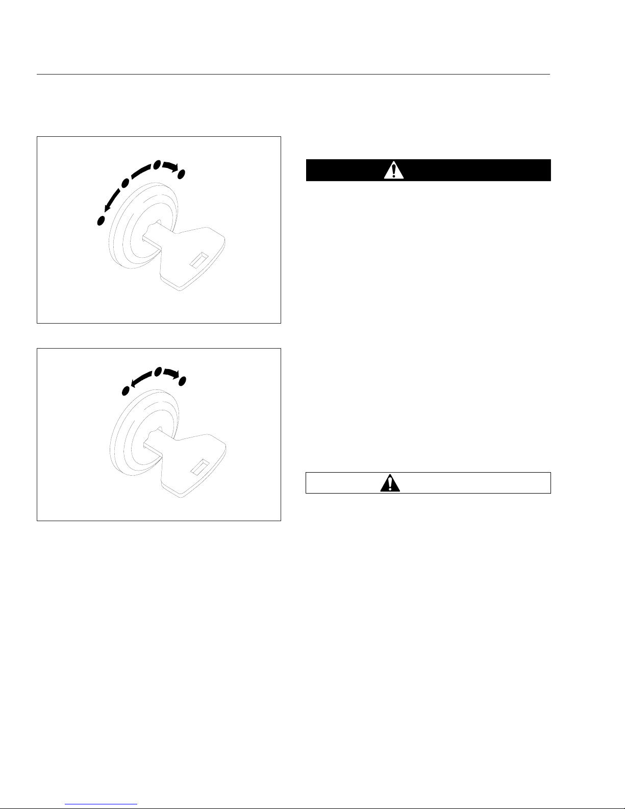
IMPORTANT: When the engine is started, it
takes a short time to build up a lubricating oil
film between the shafts and bearings, and between the pistons and cylinder walls. The oil
pressure gauge indicates any drop in lubricating
oil pressure within 15 seconds of engine startup.
See the Cummins Operation and Maintenance
Manual for minimum idle oil pressure specifications.
CNG Safety Precautions
DANGER
Natural gas is highly flammable. Failure to observe the following safety precautions could lead
to the ignition of the natural gas, which could
cause serious bodily injury or death.
CNG General Safety Information
Since compressed natural gas is highly flammable, if
you should smell gas, immediately shut off all engines and ignition sources. Avoid causing sparks,
and stay away from arcing switches and equipment.
Extinguish any cigarettes, pilot lights, flames, or other
sources of ignition in the area and adjacent areas.
Immediately provide extra ventilation to the area. Do
not start the engine or any other type of equipment
until the gas leak is corrected and the area cleared
of natural gas.
Natural gas is odorless before a scent is added for
safety. Natural gas is also colorless and nontoxic.
Still, at high enough concentration, natural gas can
suffocate a person simply by excluding adequate
oxygen to sustain life.
Natural gas is flammable in concentrations ranging
from 4 percent to 16 percent by volume in air.
WARNING
When bleeding the dispensing hose after filling
the tank, the handle gets extremely cold. This
may freeze the hands if appropriate safety gloves
are not used.
When filling the vehicle tanks with compressed natural gas (CNG), vent the dispensing hose before disconnecting it from the vehicle. The pressure in the
hose may cause a disconnected hose to become uncontrollable.
CNG storage tanks have a limited usable life-span,
due to the high pressures that they must sustain. Periodic inspections are required by law to ensure continued safety in their use.
If a tank receives an impact or has deep scratches or
gouges, it should be inspected before refilling.
07/10/96
1
2
3
4
f601179
1. Accessory (optional)
2. Off
3. On
4. Start
Fig. 8.1, Four-Position Ignition Switch
05/10/2001
1
2
3
f601179a
1. Off 2. On 3. Start
Fig. 8.2, Three-Position Ignition Switch
Compressed Natural Gas Fuel System
8.3
Page 65

CNG Workshop Precautions
Because natural gas is less dense than air, it rises.
The shop ceiling needs to be equipped with a vent
system that will allow the gas to escape and dissipate.
Use only safety fluorescent extension shop lights.
Ordinary light bulbs can explode if dropped, possibly
causing a fire.
The shop must be equipped with an alarm system
that activates when gas concentration in the air becomes dangerous.
Fire extinguishers should be the CO
2
type (ABC
minimum) and should be strategically located, highly
visible, and easily accessed.
Permit no smoking or other ignition sources in the
shop area.
Servicing the CNG System
Observe the following safety precautions when servicing natural-gas-powered vehicles:
•
Before making non-CNG system repairs on a
CNG vehicle, close the shutoff valve at the outlet of the CNG container, and keep it closed
throughout the repair procedure. Have the
CNG system checked by a qualified technician
before reopening the fuel shutoff valve.
•
Allow only qualified technicians trained in automotive CNG system repair to perform repairs.
•
Close the fuel shutoff valve(s) before performing maintenance and repairs, and when storing
the vehicle inside. Open the valve(s) only if
natural gas is needed to operate the engine or
to check for leaks.
•
Vent the gas outdoors to a safe location.
•
Always use a natural gas detector to test the
system for leaks, whether an odor is present or
not. Commercial compressed natural gas normally contains an odor-producing chemical to
enable users to detect leaks by smell. But because the odor-producing chemical can fade, a
leak detector is necessary.
•
Routinely inspect the fuel tanks, the fuel filtering and regulating mechanisms, and the fuel
lines. Use a natural gas detector to check for
any leaks. A soap-and-water solution can be
used to pinpoint the exact location of leaks.
Replace leaking fuel tanks; repair or replace
any lines, devices, or connections that are
leaking.
•
Always tighten fasteners and fuel connections
to the required torque specification, since overtightening or undertightening could cause gas
leakage. Tightening to the correct torque specification is critical to the system.
Major Repair and Replacement of
CNG Parts
When a vehicle is involved in an accident or a fire
causing damage to the fuel tank, the fuel tank must
be replaced. If damage occurred to other parts of the
fuel system, also replace those parts.
Any and all replacement parts (valves, fittings, tubing, etc.) of the CNG fuel system must be designed
specifically for CNG automotive use and must be officially approved and rated for the pressures and conditions that pertain.
Install parts and components in accordance with the
manufacturer’s instructions.
Replace (do not repair) damaged fuel lines. When
replacing fuel lines, install the lines securely in a protected location, or shield them from heat sources and
from contact with unsecured objects. Before assembly, apply a natural gas-impervious pipe thread jointing material to all male pipe threads. Ensure that all
lines and fittings are clear and free of cuttings,
threading burrs, and scales, and that the ends of all
lines are reamed. Protect lines passing through a
panel by means of grommets or similar devices. Locate joints and connections so that they are accessible.
Do not use aluminum or copper pipe, tubing, or fittings between the fuel tank and the first-stage pressure regulator because of the high pressure involved.
Ensure that shutoff valves have a rated service pressure not less than the rated service pressure of the
entire fuel supply system, and that they are capable
of withstanding a hydrostatic test of at least four
times the rated service pressure.
Compressed Natural Gas Fuel System
8.4
Page 66

9
Hybrid Electric Vehicle
Safety Precautions ................................................................ 9.1
Foot Pedal-Operated Parking Brake .................................................. 9.1
Engine Starting and Shutdown ...................................................... 9.1
T-Handle Shifter .................................................................. 9.3
Disabling the Hybrid Electric Vehicle (HEV) System ..................................... 9.4
In Case of an Emergency .......................................................... 9.5
Page 67
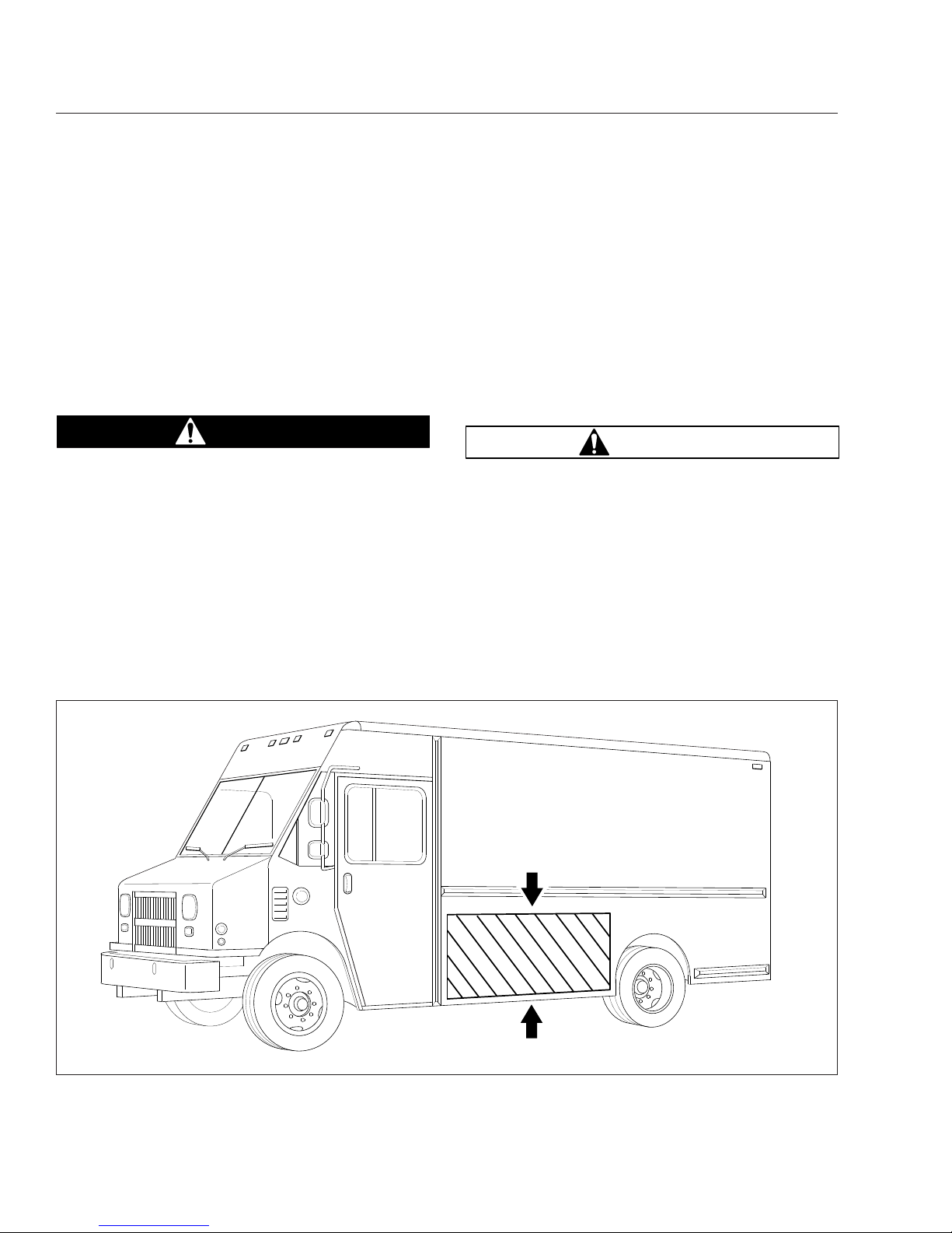
Safety Precautions
The hybrid electric vehicle (HEV) has high-voltage
components, including 340-volt Direct Current (DC)
batteries and a 500-volt Alternating Current (AC)
motor.
Never touch or cut high-voltage cables or connectors. If it is necessary to remove occupants using
cutting equipment, avoid high-voltage cables and the
Power Electronics Carrier (PEC). See
Fig. 9.1 for the
location of the high-voltage cables and PEC.
DANGER
Unprotected contact with any live high-voltage
components can cause serious injury or death.
Foot Pedal-Operated Parking
Brake
To set the foot pedal-operated parking brake, place
the gear selector in Neutral (N) and depress the
parking brake foot pedal down to the floor. To release
the parking brake, press the parking brake release
knob located on the dash. See
Fig. 9.2.
Engine Starting and Shutdown
Engine Starting
IMPORTANT: When starting the engine it is recommended that the operator’s foot be firmly
pressing the service brake pedal.
1.
Set the parking brake.
IMPORTANT: The hybrid drive transmission has
a parking pawl that engages when Park (P) is
selected.
WARNING
The vehicle could roll away if the parking brake
is not set, which could result in personal injury
or property damage.
2.
Start the engine with the key, or, if equipped with
an ignition reader, position the wristband approximately 1 inch (25 mm) above the electronic
wristband reader on the ignition pad and press
the green button located on the ignition reader
for approximately one second. Continue to press
and hold the green button to start the engine.
See
Fig. 9.3.
05/20/2010 f151096a
Fig. 9.1, Power Electronics Carrier (PEC) Location
Hybrid Electric Vehicle
9.1
Page 68

3.
Press and hold the service brake pedal.
4.
Release the parking brake. See Fig. 9.2.
5.
While continuing to press the service brake
pedal, press Reverse (R), Neutral (N), or Drive
(D) on the electronic push-button shifter to put
the vehicle into gear.
Engine Shutdown
1.
With the vehicle stopped, press and hold the service brake pedal.
2.
Press Park (P) on the electronic push-button
shifter, if so equipped.
WARNING
The vehicle could roll away if the parking brake
is not set, which could result in personal injury
or property damage.
3.
Apply the parking brake.
4.
Press and hold the red button located on the ignition reader, until the engine shuts down.
Idle-Off Shutdown Procedure
Some vehicles may be equipped with an idle-off option. A warning label like the one shown in Fig. 9.4
will be displayed in vehicles with this option. For the
idle-off feature to activate, all of the following conditions must be met for 4 seconds:
•
transmission shifter is in drive (D)
•
vehicle grade sensor range is between –10%
to 10%
•
HEV battery charge is more than 30%
•
battery voltage is greater than 12.3V
•
previous vehicle speed (at first key start) is
above 5 mph (8 km/h)
•
service brake is applied
•
seat belt is fastened
03/14/2006
f430466
1
2
1. Parking Brake Foot Pedal
2. Parking Brake Release Knob
Fig. 9.2, Foot Pedal-Operated Parking Brake
f610791
1
03/09/2006
2
1. Ignition Off (red) 2. Ignition On (green)
Fig. 9.3, Ignition Reader (optional on some vehicles)
Hybrid Electric Vehicle
9.2
Page 69

•
ABS/HSA faults are not active
•
engine fault is not active
•
hood is closed
•
air pressure is more than 65 psi (448 kPa)
•
steering pressure is less than 600 psi (4137
kPa)
•
HEV fault is not active
T-Handle Shifter
The hybrid electric vehicle (HEV) is equipped with an
Eaton automated manual transmission. A T-handle
shift control is used by the driver to select the transmission ranges. See
Fig. 9.5.
P (Park)
Use park when turning the engine on or off, to check
vehicle accessories, or to operate the engine in idle
for longer than 5 minutes. This position places the
transmission in neutral and engages the park pawl of
the transmission.
NOTE: This does not apply the parking brake.
The park pawl effectively grounds the transmission output shaft, thereby preventing rotation of
the driveline. Provided the vehicle is stationary,
selecting P (Park) on the shift selector places
the transmission in Neutral and engages the
park pawl.
R (Reverse)
The reverse position selects the reverse gear once
the vehicle speed is less than 2 mph (3 km/h). When
the selector is in reverse, the reverse warning signal
will sound. Always bring the vehicle to a complete
stop before shifting from a forward range to reverse,
or from reverse to a forward range.
Do not idle in reverse for more than 5 minutes. Select P (park), or N (neutral) when time at idle exceeds 5 minutes.
N (Neutral)
The neutral position places the transmission in neutral. This position is used when starting the engine
and for stationary operation.
When neutral is selected, the vehicle service brakes,
parking brake, or emergency brake must be applied.
Selecting neutral does not apply vehicle brakes unless an auxiliary system to apply the parking brake is
installed.
Do not let the vehicle coast in neutral. If the vehicle
is allowed to coast in neutral, the engine brake will
not work and you could lose control of the vehicle.
D (Drive)
The drive position selects the default start gear and
automatically upshifts and downshifts. In the drive
position, the transmission will initially go into first
range when drive is selected. As vehicle speed increases, the transmission will upshift automatically
through each available range up to fourth range or
06/03/2010
WARNING
SHIFT TO PARK AND APPLY PARKING BRAKE BEFORE EXITING
THE VEHICLE OR LEAVING THE DRIVER’S SEAT.
ENGINE MAY START AND STOP AUTOMATICALLY RESULTING IN
VEHICLE MOVEMENT IF LEFT UNATTENDED.
SEE OWNER’S MANUAL FOR ADDITIONAL SAFETY INSTRUCTIONS
24−01703−000
f080165
Fig. 9.4, Idle-Off Warning Label
06/25/2010 f270162
Fig. 9.5, T-Handle Shift Control
Hybrid Electric Vehicle
9.3
Page 70

fifth range. As the vehicle slows, the transmission will
downshift automatically.
When going downhill, downshift to a lower transmission range to increase engine braking and to help
maintain control. During downhill operation, the transmission may upshift to the next higher range, if the
engine is exceeding its governed speed in the lower
range.
H (Hold)
This hold position on the T-handle shifter holds the
transmission in the current gear.
1 (Low Gear)
Use first range when pulling through mud or deep
snow, when maneuvering in tight spaces, or when
driving up or down very steep grades. First range
provides the vehicle with its maximum driving torque
and maximum engine braking effect.
Disabling the Hybrid Electric
Vehicle (HEV) System
The following information describes the three methods to disable the HEV system.
Option 1 (preferred method)
Turn off the ignition, or if equipped with an ignition
reader, press the red button on the ignition pad. See
Fig. 9.3.
•
The engine will shut down.
•
The dash lights will shut down.
•
The HEV system will shut down.
•
The HEV batteries are still active, but are isolated in the Power Electronics Carrier (PEC).
Option 2
Disconnect the low-voltage (12 volt) vehicle batteries.
See Fig. 9.6.
•
The engine will shut down.
•
The HEV system will shut down.
•
The HEV batteries are still active, but are isolated in the Power Electronics Carrier.
Option 3
Push in the service switch in the Power Electronics
Carrier and shut down the engine. See
Fig. 9.7.
IMPORTANT: The red service switch on the
PEC should only be used for an emergency
shutdown or when the service manual or
troubleshooting guide directs the Hybrid-Trained
Technician to perform work on the high- voltage
system.
•
Hybrid system will be disabled
05/26/2006 f151097
1
2
1. Passenger Steps 2. Ground Cable
Fig. 9.6, Battery Location
04/22/2009 f545519
Fig. 9.7, Service Switch
Hybrid Electric Vehicle
9.4
Page 71
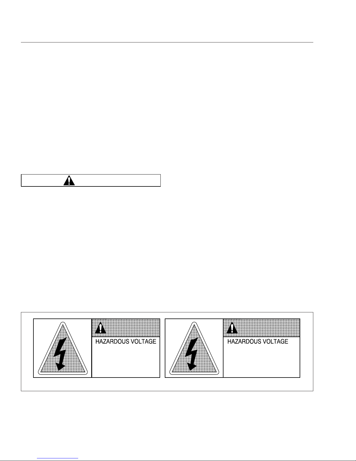
•
HEV batteries are still "live" but are isolated in
the PEC.
IMPORTANT: These procedures should only be
used for an emergency. If service is required on
the vehicle, refer to the "Hybrid Services Shutdown" procedure found in TRSM1000 located
on
www.roadranger.com.
In Case of an Emergency
1.
When conditions allow, pull the vehicle onto the
shoulder of the road and stop.
2.
Apply the parking brake.
WARNING
The vehicle could roll away if the parking brake
is not set, which could result in personal injury
or property damage.
3.
Push Park (P) on the electronic push-button
shifter, if so equipped.
4.
Turn the ignition key off, or, if equipped with an
ignition reader, press the red button on the ignition pad to turn off the ignition.
5.
Exit the vehicle.
If the HEV becomes involved in an accident or
fire, be aware of the following:
•
Use CO2 or dry chemical extinguishers.
Lithium ion batteries are contained in the
Power Electronics Carrier (PEC).
•
The high-voltage wiring is covered in orange insulation or convoluted tubing and
marked with warning labels at the connectors.
•
All Eaton® Hybrid Electric vehicles will be
marked ’Hybrid’ on the outside of the vehicle, along with the shift label on the dash.
•
Do not cut into or open the PEC.
•
Do not cut into or open the DC/AC converter.
•
Do not cut into or open the inverter.
•
Do not cut into high-voltage cables.
•
Do not cut into the passenger side of the
body. The PEC is located behind the sheet
metal. See
Fig. 9.1.
High-Voltage Safety Features
All high-voltage safety cables are covered in orange
insulation and clearly labeled near each connector
end. Each high-voltage component is clearly tagged
with a warning or danger label. See
Fig. 9.8.
12/04/2007
To reduce risk of possible serious
injury (Shock, Burn or Death):
Components marked with High
Voltage should be avoided.
Service must be performed by
qualified personnel only.
You will be severely injured or killed
if you do not follow the procedure.
Components marked with
DANGER High Voltage should be
avoided. Service must be
performed by qualified personnel only.
f080151
DANGERWARNING
Fig. 9.8, High-Voltage Warning and Safety Labels
Hybrid Electric Vehicle
9.5
Page 72

10
Pre- and Post-Trip
Checklists
Pretrip and Post-Trip Inspection General Information ................................... 10.1
Daily Pretrip Inspection and Maintenance Checklist ..................................... 10.2
Weekly Post-Trip Inspection and Maintenance Checklist ................................. 10.3
Monthly Post-Trip Inspection and Maintenance Checklist ................................ 10.3
Page 73

Pretrip and Post-Trip
Inspection General Information
Regulations in both Canada and the United States
clearly indicate that it is the driver’s responsibility to
perform an inspection and ensure the complete roadworthiness of a vehicle, before placing it into service
for the day. Commercial vehicles may be subject to
inspection by authorized inspectors, and an unsafe
vehicle can be put "out of service" until the driver or
owner repairs it.
Use the pretrip inspection checklist to ensure that
vehicle components are in good working condition
before each trip. Use the weekly and monthly posttrip inspection checklists to note any items that require attention before the next trip. A driver that is
familiar with the vehicle, and drives it regularly, can
perform the daily inspections, then add the weekly
and monthly post-trip inspections as scheduled. If the
driver does not operate the vehicle on a consistent
basis, all three of the inspection procedures should
be performed before the trip.
Pretrip and post-trip inspections cannot be done
quickly. However, careful inspections save time by
eliminating stops later to adjust items overlooked or
forgotten.
Numbers in parentheses within each of the checklists
reference the corresponding detailed instructions
found under "Daily (D), Weekly (W), or Monthly (M)
Procedures in
Chapter 11.
If any system or component does not pass this inspection, it must be corrected before operating the
vehicle. Whenever equipment requires adjustment,
replacement, repair, addition of lubricants, or a
change of lubricants, see the Walk-In Van Chassis
Workshop Manual for procedures and specifications,
or take the vehicle to an authorized Freightliner
dealer.
IMPORTANT: The pretrip and post-trip checklists
in this chapter, and the maintenance procedures
detailed in
Chapter 11 and in the Walk-In Van
Chassis Maintenance Manual are not all inclu-
sive. Also, refer to the inspection and maintenance instructions of the major component
manufacturers and the body manufacturer.
Pre- and Post-Trip Checklists
10.1
Page 74

Daily Pretrip Inspection and
Maintenance Checklist
IMPORTANT: Before performing any checks,
apply the parking brake and chock the tires.
See Table 10.1 for a checklist of the procedures that
should be performed daily, before the first trip.
Procedure Performed
(check off)
Daily Pretrip Inspections/Checks
Procedure
Reference
_______
Drain manually drained air reservoirs (that are not equipped with automatic drain
valves)
D1
Check _______ surge tank coolant level D2
Inspect _______ radiator and charge air cooler D3
Check _______ engine for fuel, oil, or coolant leaks D4
Check _______ CNG engines for natural gas leaks, using a natural gas detector D4
Check _______ intake-air restriction indicator and air intake system D5
Check _______ engine oil level D6
Check _______ automatic transmission fluid level, if equipped D7
Check _______ fuel/water separator for contaminants and leaks, if equipped D8
Check _______ fuel tank(s), fuel lines, and connections D9
Check _______ fuel level D10
Check _______ diesel engine fuel cap vent area is clean D10
Check _______ CNG engine pressure gauge mounted in fuel fill box D10
Check _______ front and rear suspension components D11
Check _______ oil- and air-pressure warning systems D12
Check _______ horn D13
Check _______ backup alarm, if equipped –
Check _______ headlights, mirrors, and window glass D14
Check _______ air brake chambers and pushrods D15
Check _______ slack adjusters D16
Check _______ tire pressure D17
Check _______ tire condition D18
Check _______ rims and wheels D19
Check _______ air brake system D20
Check _______ parking brakes D21
Inspect _______ frame rails (missing bolts), crossmembers (bent or loose) –
Check _______
mud flaps (aren’t damaged, at least 10 inches above the ground, and brackets
are secure)
–
Check _______
exhaust system (mounted securely, connected tightly, no signs of leaks such as
soot trails)
–
Check _______ Bendix Hydro-Max® brake booster D22
Inspect _______ engine and chassis wiring D23
_______ remove chocks and test service brakes D24
Inspector___________________________________________________ Date ________________
Table 10.1, Daily Pretrip Inspection and Maintenance Checklist
Pre- and Post-Trip Checklists
10.2
Page 75

Weekly Post-Trip Inspection
and Maintenance Checklist
IMPORTANT: Before performing any checks,
apply the parking brake and chock the tires.
See Table 10.2 for a checklist of the procedures that
should be performed weekly, post-trip.
Procedure Performed
(check off)
Weekly Post-Trip Inspections/Checks
Procedure
Reference
_______ Manually drain air reservoirs that are equipped with automatic drain valves —
Inspect _______ batteries and battery cables W1
Check _______ wheel bearing lubricant level W2
Inspect _______ steering components W3
Check _______ drive belts W4
Check _______ drive belt tension W5
Inspect _______ seat belts and tether belts —
Inspector___________________________________________________ Date ________________
Table 10.2, Weekly Post-Trip Inspection and Maintenance Checklist
Monthly Post-Trip Inspection
and Maintenance Checklist
IMPORTANT: Before performing any checks,
apply the parking brake and chock the tires.
See Table 10.3 for a checklist of the procedures that
should be performed monthly, post-trip.
Procedure Performed
(check off)
Monthly Post-Trip Inspections/Checks
Procedure
Reference
_______ Clean the battery terminals M1
Inspect _______ radiator hoses and heater hoses M2
Check _______
fluid level in the hydraulic clutch reservoir (if applicable, and if necessary, fill with
DOT 6 brake fluid)
—
Check _______ fluid level in the hydraulic brake fluid reservoir, if equipped M3
Check _______ steering wheel play M4
Check _______ outer surfaces of the hood and body (for visible surface breaks and damage) —
Inspect _______ brake lining wear M5
Inspect _______ driveshaft —
Inspector___________________________________________________ Date ________________
Table 10.3, Monthly Post-Trip Inspection and Maintenance Checklist
Pre- and Post-Trip Checklists
10.3
Page 76

11
Pre- and Post-Trip
Inspections and
Maintenance
Safety Precautions ............................................................... 11.1
Daily Pretrip Inspection and Maintenance Procedures ................................... 11.1
Weekly Post-Trip Inspection and Maintenance Procedures ............................... 11.9
Monthly Post-Trip Inspection and Maintenance Procedures ............................. 11.11
Page 77

Safety Precautions
DANGER
When working on the vehicle, shut down the engine, set the parking brake, and chock the tires.
Before working under the vehicle, always place
jack stands under the frame rails to ensure the
vehicle can not drop. Failure to follow these
steps could result in serious personal injury or
death.
Daily Pretrip Inspection and
Maintenance Procedures
Whenever equipment requires adjustment, replacement, repair, addition of lubricants, or a change of
lubricants, see the Walk-In Van Chassis Workshop
Manual for repair procedures and specifications.
Specific references to the manual will be found
where appropriate.
1.
Drain manually drained air reservoirs (that are
not equipped with automatic drain valves).
Water and oil normally enter the air reservoir in
the form of vapor because of the heat generated
during compression. After the water and oil condense, drain the resulting emulsion as follows:
1.1
Open the wet tank valve. The drain cock
or pull chain drain is located on the forward end of the supply air reservoir, which
is connected directly to the air compressor. Block the valve open.
WARNING
When draining the air reservoir, do not look into
the air jets or direct them toward anyone. Dirt or
sludge particles may be in the airstream and
could cause injury.
1.2
Exhaust the remaining air and moisture
from the system by opening the drain
cocks on the bottoms of the remaining air
reservoirs. Block the valves open.
1.3
Water and oil emulsion often form pockets
that will not drain while compressed air is
in the reservoirs. Because of these pockets, leave the valves blocked open during
the first part of the pretrip inspection.
2.
Check the coolant level in the surge tank.
See
Fig. 11.1. If the coolant is low, add a 50/50
mixture of water and the type of antifreeze currently installed in your vehicle. Fill the surge tank
with coolant to the MAX line when the tank is
cool. See
Table 11.1 for approved coolants. If
the surge tank was empty, start the engine after
refilling, then check the level again when the engine is at operating temperature.
Approved Coolants
Engine Type Coolant Manufacturer
Coolant
Designation
*
Diesel
Old World Industries Fleet Charge®
Shell
Shell HD/N
Antifreeze
Texaco JC04 Antifreeze
Van Waters and
Rogers Ltd. (Canada)
Diesel Antifreeze
No. 6038
Gasoline
Propane
GM
GM DEX-
COOL®
†
*
Freightliner-approved antifreeze must meet one of the following conditions: A. Ethylene glycol solution that meets GM 6038–M Engineering
Standards. B. Ethylene glycol solution that has less than 0.1% anhydrous
sodium metasilicate and meets either GM 1825–M or GM 1899–M Engineering Standards.
†
GM DEX-COOL is approved for use in gasoline and propane engines
only.
Table 11.1, Approved Coolants
05/31/2007
f200705
Fig. 11.1, Surge Tank Fill Cap
Pre- and Post-Trip Inspections and Maintenance
11.1
Page 78

NOTICE
Coolant must be filled to the full line of the surge
tank. Low coolant could result in engine overheating, which could cause engine damage.
3.
Inspect the radiator and charge air cooler.
3.1
Inspect the radiator and charge air cooler
for clogged fins. Use compressed air or
water directed from the fan side of the
core to backflush any material restricting
airflow.
3.2
Inspect the radiator and charge air cooler
for damage and accumulated debris.
Straighten bent or damaged fins to permit
airflow across all areas of the cores.
NOTE: When traveling through areas of high
insect concentration, it may be necessary to
clean the exterior of the radiator or the
charge air cooler core as often as every 200
miles (320 km).
3.3
Also inspect and clean the condenser. If
clogged, the condenser can restrict airflow
through the radiator.
3.4
Check the radiator for leaks. If leaks are
found, have the radiator repaired or replaced. Take the vehicle to an authorized
Freightliner dealer for assistance.
4.
Inspect the engine for fuel, oil, and coolant leaks.
On vehicles equipped with a compressed natural
gas (CNG) engine, use a natural gas detector to
check for natural gas leaks.
Correct any leaks found.
5.
Inspect the air intake system for leaks or damage.
NOTICE
Failure to maintain a sealed air intake system
could allow entry of dirt and contaminants into
the engine. This could adversely affect engine
performance and result in engine damage.
5.1
Check the intake-air restriction indicator, if
so equipped.
5.2
Replace the primary filter element in the
air cleaner when filter restriction reaches
25 inH
2
O for Cummins engines or 15
inH2O for GM engines. See Group 09 of
the Walk-In Van Chassis Workshop
Manual for filter element replacement instructions, or take the vehicle to an authorized Freightliner dealer. See
Fig. 11.2
and Fig. 11.3.
NOTE: After replacing the filter element,
reset the restriction indicator by pressing the
rubber reset button, if so equipped.
5.3
Inspect the secondary or safety filter element in the air cleaner when replacing the
primary element, and replace it when
clogged or dirty. This element should be
replaced with every third primary element
replacement.
5.4
Check the engine air intake piping from
the air cleaner to the engine intake. Inspect the piping for loose connections,
cracks, torn or collapsed hoses, punctures, and other damage. Tighten loose
09/09/2014 f090509
To replace the filter, the canister must be replaced.
Fig. 11.2, Farr Air Cleaner Filter Element
Pre- and Post-Trip Inspections and Maintenance
11.2
Page 79

connections, and have damaged components replaced. Make sure the piping system is airtight so that all intake air passes
through the air cleaner.
6.
Check the engine oil level.
NOTICE
Operating the engine with the oil level below the
minimum fill (or "add") mark or above the maximum fill (or "full") mark could result in engine
damage.
6.1
Park the vehicle on a level surface. Allow
several minutes for the oil to drain back
into the oil pan to ensure an accurate
reading.
NOTE: Follow the engine manufacturer’s
guidelines for engine shutdown time requirements prior to checking the oil level.
6.2
Pull out the dipstick and clean it with a
paper towel or cloth, then push the dipstick back in all the way. Remove it again,
keeping the tip down, and check the oil
level.
6.3
If the oil is below the cross-hatched area,
or the add mark, at the tip of the dipstick,
add at least one quart (liter) of the recommended oil. See
Fig. 11.4 for diesel en-
gines and
Fig. 11.5 for gasoline and liquid
propane gas (LPG) engines.
For diesel engines that comply with
EPA07 or newer regulations, use CJ-4
engine oil with less than 1% sulfated ash.
For gasoline and LPG engines, use SAE
5W–30 oil that meets GM standard
GM6094M and has the American Petroleum Institute (API) symbol. Do not use
SAE 10W–40 or 20W–50.
NOTICE
Failure to use the recommended oil can result in
engine or aftertreatment component damage and
will void the warranty.
7.
Check the oil level in the automatic transmission.
NOTE: The fluid must be warm to ensure an
accurate check. The fluid level rises as temperature increases.
09/03/2010 f090481
1
1. Primary Filter Element
Fig. 11.3, Donaldson Air Cleaner Filter Element
10/26/2012 f012203
FULL ADD 2 QT
Fig. 11.4, Oil Dipstick (diesel engine)
08/05/2010 f012186
Oil should be within the cross-hatched area of the
dipstick.
Fig. 11.5, Oil Dipstick (gasoline and propane engines)
Pre- and Post-Trip Inspections and Maintenance
11.3
Page 80

With the vehicle on a level surface, check the oil
level in the transmission using one of the following procedures:
Hot Check
•
Operate the transmission in a Drive (D) range
until normal operating temperature, 160 to
200°F (71 to 93°C), is reached.
•
Park the vehicle. Shift to Neutral (N) and apply
the parking brake. Let the engine run at idle.
•
Wipe the dipstick clean and check the fluid
level. A safe operating level is any level within
the HOT-run (upper) band on the dipstick. See
Fig. 11.6.
•
If the fluid is not within this range, add or drain
fluid as needed to bring the level to the top of
the HOT-run band. See the Walk-In Van Chas-
sis Maintenance Manual for fluid types and capacities.
IMPORTANT: Do not drain the fuel/water separator completely. Drain no more than three
tablespoons of fluid at a time.
8.
Check the fuel/water separator for contaminants
and leaks.
IMPORTANT: When draining fluid from a fuel/
water separator, drain the fluid into an appropriate container and dispose of it properly. Many
states now issue fines for draining fuel/water
separators on the ground. On all types of separators, stop draining fluid when you see fuel
come out of the separator drain valve.
9.
Inspect the fuel tanks, fuel lines, and connections
for leaks.
On vehicles equipped with a compressed natural
gas (CNG) engine, inspect the fuel tanks, fuel
regulators, fuel filters, and the fuel lines. Use a
natural gas detector to check for any leaks, or
spray the components with a soap-and-water
solution and check for bubbles.
9.1
Check that the fuel tanks are secured to
their mounting brackets and that the
mounting brackets are secured to the
frame.
9.2
Replace leaking fuel tanks.
9.3
If lines or connections are leaking, have
them repaired or replaced.
For repair and/or replacement procedures,
see Group 47 of the Walk-In Van Chassis
Workshop Manual, or take the vehicle in
to an authorized Freightliner dealer.
9.4
If equipped with fuel tank shutoff valves,
be sure the valves are fully open.
WARNING
Never operate the engine with the fuel tank shutoff valves partly closed. This could damage the
fuel pump, causing sudden loss of engine power,
possibly resulting in serious personal injury due
to reduced vehicle control.
10.
Check the fuel level in the fuel tank(s).
On vehicles equipped with a diesel engine be
sure that the fuel cap vent area is clean. Check
the fuel/water separator (if so equipped) for leaks
and, if needed, prime the fuel tank system.
On vehicles equipped with a compressed natural
gas (CNG) engine, check the pressure gauge
mounted in the fuel fill box to determine the
amount of fuel in the fuel tanks.
WARNING
Never fill fuel tanks to more than 95 percent of
their liquid capacity. This could make them more
likely to rupture from impact, possibly causing
fire and resulting in serious personal injury or
death by burning.
02/27/2002
f270077
A
B
A. Hot-Run Band B. Cold-Run Band
Fig. 11.6, Automatic Transmission Dipstick Markings
Pre- and Post-Trip Inspections and Maintenance
11.4
Page 81

IMPORTANT: Use only ultralow-sulfur diesel
(ULSD) fuel with 15 ppm sulfur content or
less, based on ASTM D2622 test procedure.
Failure to use ultralow-sulfur diesel fuels
may void the warranty on emissions components.
10.1
To keep condensation to a minimum, fill
diesel fuel tanks at the end of each day,
but not to more than 95 percent of liquid
capacity. Select the proper grade of fuel,
as specified by the engine manufacturer.
WARNING
Do not mix gasoline or alcohol with diesel fuel.
This mixture could cause an explosion, possibly
resulting in serious personal injury or death. Do
not fill the fuel tanks in the presence of sparks,
open flames, or intense heat. These could ignite
the fuel, possibly causing severe burns.
10.2
Always strain or filter diesel fuel before
putting it into the tanks. This will lengthen
the life of the engine fuel filter and reduce
the chances of dirt entering the engine.
11.
Inspect the front and rear suspension components, including springs, spring hangers, shocks,
and suspension brackets.
11.1
Check for broken spring leaves, loose
U-bolts, cracks in the suspension
brackets, and loose fasteners in the spring
hangers and shackles.
11.2
Inspect the shock absorbers for loose fasteners and leaks.
11.3
Tighten all loose fasteners and have any
components replaced that are worn,
cracked, or otherwise damaged.
11.4
On vehicles with air suspensions, check
for leaks. Check air suspension components for cuts and bulges.
WARNING
Do not replace individual leaves of a damaged
front or rear suspension leaf spring assembly;
replace the complete spring assembly. Visible
damage, such as cracks or breaks, to one leaf
causes hidden damage to other leaves. Replace-
ment of only the visibly damaged part(s) is no
assurance that the spring is safe. If cracks or
breaks exist on front spring assemblies in either
of the two top leaves, a loss of vehicle control
could occur. Failure to replace a damaged spring
assembly could cause an accident resulting in
serious personal injury or property damage.
12.
Check the oil- and air-pressure warning systems.
When the engine is started, oil- and air-pressure
warnings will come on until the oil and air pressure rise above a preset minimum. After starting
the engine, make sure the oil- and air-pressure
warning systems are operating and that the
buzzer stops sounding when the preset minimum
is reached.
12.1
If the warning systems do not come on
when the ignition is turned on, have the
systems repaired.
12.2
If the air pressure in both systems is
above the preset minimum when the engine is started, test the low air pressure
system by lowering the pressure to below
this range, or until the warning system
comes on.
NOTE: The air pressure in both the primary
and secondary air reservoir systems must
be above 65 psi (448 kPa) on most vehicles.
13.
Make sure that the electric horn works.
If a horn is not working, have it replaced before
trip departure.
14.
Make sure all the exterior lights are working.Check the high and low beams of the head-
lights. Clean the windshield, side, and rear windows (if equipped) with a long-handled or
telescoping window cleaning device and standard cleaning solutions. Stand only on the
ground, on a stepladder, or an elevated walkway.
The vehicle entry/exit steps and handholds are
not designed for this purpose. The tires, fenders,
engine, and other under-hood components do
not have adequate gripping surfaces and handholds.
DANGER
Do not loosen or remove the parking brake clamp
ring for any purpose. See
Fig. 11.7. The parking/
emergency brake section of the brake chamber is
Pre- and Post-Trip Inspections and Maintenance
11.5
Page 82

not intended to be serviced. Serious injury or
death may result from sudden release of the
power spring.
Before doing any repairs or adjustments on a
service/parking brake chamber, read the applicable warnings and instructions in Group 42 of
the Walk-In Van Chassis Workshop Manual.
15.
Inspect the air brake chamber and the air brake
chamber pushrods. See
Fig. 11.7.
16.
Inspect the slack adjusters.
16.1
Meritor Slack Adjusters: Check the boot
for cuts, tears, or other damage. Have it
replaced if necessary.
16.2
Inspect the slack adjuster boot for cuts or
tears. If the boot is damaged, have it replaced. See
Fig. 11.8.
17.
Check tire inflation pressures using an accurate
tire pressure gauge.
Tires should be checked when cool. For inflation
pressures and maximum loads (per tire) see the
tire manufacturer’s guidelines.
17.1
Be sure valve stem caps are on every tire
and that they are screwed on finger-tight.
17.2
Inflate the tires to the applicable pressures
if needed.
17.3
If a tire has been run flat or underinflated,
check for possible wheel or tire damage
before adding air.
Moisture inside a tire can result in body
ply separation or a sidewall rupture. During tire inflation, compressed air reservoirs
and lines must be kept dry. Use well maintained inline moisture traps and service
them regularly.
WARNING
Do not operate the vehicle with underinflated or
overinflated tires. Incorrect inflation can stress
the tires and make the tires and wheels susceptible to damage, possibly leading to wheel or tire
failure and loss of vehicle control, resulting in
serious personal injury or death.
IMPORTANT: The load and cold inflation
pressure must not exceed the wheel manufacturer’s recommendations, even though
the tire may be approved for a higher load
1
A
02/22/2000
f421352
A. Do not remove this clamp ring.
1. MGM TR-T (TR Series) Brake Chamber shown
Fig. 11.7, Parking Brake Chamber Clamp
f421398
06/17/2003
1
2
3
4
5
6
7
8
10
9
1. 7/16-inch Adjusting
Nut
2. Grease Fitting
3. Boot
4. Link
5. Brake Chamber Piston
Rod
6. Clevis
7. ½-inch Clevis Pin
8. 1/4-inch Clevis Pin
9. Grease Relief
Opening
10. Slack Adjuster Spline
Fig. 11.8, Automatic Slack Adjuster (typical)
Pre- and Post-Trip Inspections and Maintenance
11.6
Page 83

inflation. Some wheels are stamped with a
maximum load and maximum cold inflation
rating. If they are not stamped, consult the
wheel manufacturer for the correct tire inflation pressure for the vehicle load. If the load
exceeds the maximum wheel capacity, the
load must be adjusted or reduced.
IMPORTANT: Low-rolling resistance (LRR) tires
minimize wasted energy as a tire rolls, thereby
decreasing rolling effort and improving fuel efficiency. If tire replacement is necessary, replacement tires must meet or exceed the rolling resistance of the originally installed tires in order to
maintain compliance with greenhouse gas and
fuel efficiency regulations (GHG14).
Contact your tire manufacturer/supplier to determine the rolling resistance of the originally installed tires. Visit
www.epa.gov/smartway for
additional information and resources.
18.
Inspect each tire for wear, bulges, cracks, cuts,
penetrations, and oil contamination. A weekly
pressure loss of 4 psi (28 kPa) or more in a tire
may indicate damage. The tire should be inspected and if necessary, repaired or replaced.
18.1
Check the tire tread depth. If tread is less
than 4/32 inch (3 mm) on any front tire, or
less than 2/32 inch (1.5 mm) on any rear
tire, replace the tire.
18.2
Inspect each tire for bulges, cracks, cuts,
and penetrations.
18.3
Inspect each tire for oil contamination.
Fuel, oil, gasoline, and other petroleum
derivatives, if allowed to contact the tires,
will soften the rubber and destroy the tire.
19.
Check the wheel nuts for indications of looseness. Examine each wheel component.
19.1
Remove all dirt and foreign material from
the assembly. Dirt or rust streaks from the
stud holes, metal buildup around stud
holes, or out-of-round or worn stud holes
may be caused by loose wheel nuts. See
Fig. 11.9 and Fig. 11.10.
19.2
Examine the wheel components (including
studs and nuts) for cracks or other damage.
See Group 33 or Group 35 of the Walk-In
Van Chassis Workshop Manual for service
procedures on the studs and hubs, and
see Group 40 in the same manual for
wheel and tire servicing, or take the vehicle to an authorized Freightliner dealer.
WARNING
Have any worn or damaged wheel components
replaced by a qualified person using the wheel
manufacturer’s instructions and the wheel industry’s standard safety precautions and equipment.
Otherwise a vehicle or workshop accident could
occur, possibly resulting in serious personal injury or death.
19.3
Make sure all wheel nuts are tightened
450 to 500 lbf·ft (610 to 678 N·m) for Accuride wheels with unlubricated threads.
Use the tightening pattern in
Fig. 11.11 for
10-hole wheels and
Fig. 11.12 for 8-hole
wheels. See Group 40 of the Walk-In Van
Chassis Workshop Manual.
NOTICE
Insufficient wheel nut torque can cause wheel
shimmy, resulting in wheel damage, stud breakage, and extreme tire tread wear. Excessive
wheel nut torque can break studs, damage
threads, and crack discs in the stud hole area.
Use the recommended torque values and follow
the proper tightening sequence.
02/09/95
f400058
Fig. 11.9, Dirt and Rust Streaks from the Stud Holes
Pre- and Post-Trip Inspections and Maintenance
11.7
Page 84
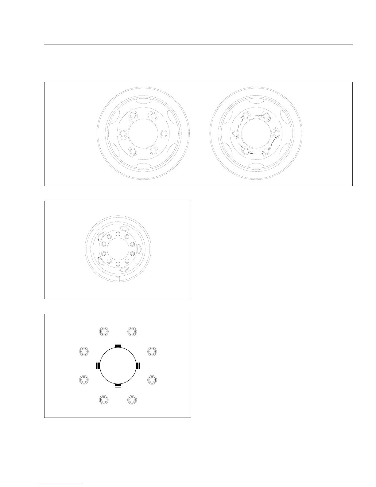
NOTE: Vehicles operating under severe or
adverse conditions should be checked more
frequently.
20.
Check the air brake system for proper operation.
20.1
Check the air governor cut-in and cut-out
pressures as follows:
Run the engine at fast idle. The air governor should cut out the air compressor at
approximately 120 psi (827 kPa). With the
engine idling, apply the brake pedal several times. The air governor should cut in
the air compressor at approximately 100
psi (689 kPa). If the air governor does not
cut in and out as described above, it must
be adjusted to these specifications. If the
air governor cannot be adjusted or repaired, replace it before operating the vehicle.
20.2
Check the air pressure buildup times as
follows:
With the air system fully charged to 120
psi (827 kPa), make one full brake application and note the air pressure reading
on the gauge. Continue to reduce the air
pressure by moderate brake applications
to a maximum of 90 psi (620 kPa), then
run the engine at governed rpm. If the
time required to raise the air pressure to
120 psi (827 kPa) (from the pressure
noted after one brake application) is more
02/09/95
f400001
Fig. 11.10, Worn Stud Holes
1
2
3
45
6
7
8
9
10
f400081a
08/23/93
Fig. 11.11, Tightening Pattern, 10-Hole Wheels
f400052a
1
2
3
4
5
6
7
8
03/08/2012
Fig. 11.12, Tightening Pattern, 8-Hole Wheels
Pre- and Post-Trip Inspections and Maintenance
11.8
Page 85

than 30 seconds, eliminate any leaks or
replace the air compressor before operating the vehicle.
20.3
Check the air pressure reserve as follows:
With the air system fully charged to 120
psi (827 kPa), stop the engine and note
the air pressure. Then make one full brake
application and observe the pressure
drop. If it drops more than 25 psi (172
kPa), all areas of leakage must be eliminated before operating the vehicle.
20.4
Check the air leakage in the system as
follows:
With the parking brake (spring brake) applied, the transmission out of gear, and
the tires chocked, charge the air system
until cut-out pressure of 120 psi (827 kPa)
is reached.
With the service brakes released, shut
down the engine, wait 1 minute and note
the air pressure gauge reading. Observe
the air pressure drop in psi (kPa) per minute.
Charge the air system until cut-out pressure of 120 psi (827 kPa) is reached. With
the parking brakes released and the service brake applied, shut down the engine,
wait 1 minute and note the air pressure
gauge reading. Observe the air pressure
drop in psi (kPa) per minute.
If leakage exceeds the limits shown in
Table 11.2, repair all areas of leakage be-
fore driving the vehicle.
Maximum Allowable Service Brake Leakage
Brakes Released Brakes Applied
2 psi/min. (14 kPa) 3 psi/min. (21 kPa)
Table 11.2, Maximum Allowable Service Brake
Leakage
21.
Test the parking brake on a 20 percent grade.
Apply the hand brake with the vehicle on a 20
percent grade (or as steep a grade that the vehicle may normally be parked on). The ramp surface should be made of Portland cement or
equivalent. If the parking brake does not hold the
vehicle, repair the parking brake system.
22.
Check the operation of the Bendix® Hydro-Max
brake booster, as follows.
22.1
With ignition off, depress the brake pedal
and listen for the back-up motor to engage. Also, note that the pedal force relieves; the pedal should depress easily.
22.2
With the ignition off, engine running, parking brake released, ensure that the
BRAKE warning indicator light is not on.
This is a dual indicator and indicates that
the parking brake is set, and warns if
there is a hydro-max failure other than
loss of back-up motor power.
23.
Inspect the engine and chassis wiring.
Check for loose wiring, chafed insulation, and
damaged or loose hold-down clamps. Tighten
loose wires or hold-down clamps; replace damaged wiring or clamps.
24.
Test the service brakes.
When starting to move the vehicle and before
picking up speed, test the brakes with the foot
pedal and parking brake control valve (yellow
knob) to be sure they will bring the vehicle to a
safe stop.
Weekly Post-Trip Inspection
and Maintenance Procedures
1.
Inspect the batteries and battery cables.
WARNING
Battery posts, terminals, and related accessories
contain lead and lead compounds, chemicals
known to the State of California to cause cancer
and reproductive harm. To prevent possible personal injury, always wash your hands after handling battery parts and related accessories.
1.1
Check the battery cables for chafing and
proper routing. Be sure the battery holddown is secure. If it is loose, tighten the
hold-down bolts; if it is damaged, replace
it. Replace the battery cable if damaged.
1.2
If the battery is equipped with a built-in
hydrometer, examine the hydrometer. If a
green dot shows in the sight glass, the
battery is sufficiently charged.
Pre- and Post-Trip Inspections and Maintenance
11.9
Page 86

If the sight glass is dark, the charge is low
and the battery must be recharged.
If the sight glass is clear, the battery has a
low level of electrolyte and must be replaced.
2.
Check the level of the wheel bearing lubricant in
the hub cap at each end of the front axle.
If needed, fill the hubs to the level indicated on
the hub cap. See
Chapter 15, for recommended
lubricants.
IMPORTANT: Before removing the fill plug, always clean the hub cap and plug.
3.
Examine the steering components.
See Fig. 11.13. If repairs are needed, see
Group 46 of the Walk-In Van Chassis Workshop
Manual for instructions, or take the vehicle to an
authorized Freightliner dealer.
3.1
Check the mounting bolts and pitman arm
nut, for tightness.
3.2
Check the drag link nuts for missing cotter
pins.
3.3
Inspect the steering drive shaft and steering linkage for excessive looseness, or
other damage.
3.4
Tighten loose nuts and have damaged
parts replaced as needed.
4.
Check the condition of the drive belts.
Check the fan belt(s), alternator belt, and refrigerant compressor belt for signs of glazing, wear
(frayed edges), damage (breaks or cracks), or oil
contamination. If a belt is glazed, worn, damaged, or oil soaked, replace the belt, following
the instructions in Group 01 of the Walk-In Van
Chassis Workshop Manual.
5.
Check the drive belt for proper tension. Use your
index finger to apply approximately 25 pounds
(11 kg) of force at the center of the belt freespan. See
Fig. 11.14. Deflection should be one
belt thickness per 1 foot (300 mm) of belt freespan. If the tension is more than or less than this
value, measure it with a belt-tension gauge and
adjust it to the proper tension. See Group 01 of
the Walk-In Van Chassis Workshop Manual for
instructions.
NOTE: On Cummins engines, a belt tensioner
automatically adjusts the fan and alternator belt
to correct tension. If the belt slips, repair or replace the tensioner. For instructions, see the
Cummins Engine Operation and Maintenance
Manual.
10/11/2001
f461916
1
1
1
2
3
3
1. Steering Gear Mounting Bolt
2. Pitman Arm Pinch Bolt Nut
3. Drag Link Nut
Fig. 11.13, Steering Gear Fasteners
10/31/94
f200036a
A
B
A. Deflection B. Belt Free-Span
Fig. 11.14, Checking Belt Tension
Pre- and Post-Trip Inspections and Maintenance
11.10
Page 87

Monthly Post-Trip Inspection
and Maintenance Procedures
WARNING
Battery posts, terminals, and related accessories
contain lead and lead compounds, chemicals
known to the State of California to cause cancer
and reproductive harm. To prevent possible personal injury, always wash your hands after handling battery parts and related accessories.
1.
Clean the batteries.
1.1
Remove any corrosion from the hold-down
and the top of the battery.
NOTICE
Take care to keep the vent plugs tight so that the
neutralizing solution does not enter any of the
battery cells and damage the battery.
1.2
Use a soda solution to neutralize the acid
present, then rinse off the soda solution
with clean water.
1.3
If the battery posts or cable terminals are
corroded, disconnect the terminals from
the posts. Clean them with a soda solution
and a wire brush. After cleaning, connect
the terminals to the battery posts, then
apply a thin coat of petroleum jelly to the
posts and terminals to help retard corrosion.
2.
Inspect the radiator and heater hoses, including
the clamps and support brackets.
2.1
Make sure the radiator inlet and outlet
hoses are pliable and are not cracking,
weakening, or ballooning.
2.2
Make sure the heater hoses are pliable
and are not cracking or ballooning. Replace hoses that show signs of cracking,
weakening, or ballooning.
2.3
Tighten hose clamps as necessary, but do
not overtighten, as hose life can be adversely affected.
2.4
Be sure the hose support brackets are
securely fastened. Make sure the hoses
are not located near sources of wear,
abrasion, or high heat.
IMPORTANT: Replace all hoses, including
heater hoses, at the same time. Service-type
knitted or braided yarn-reinforced neoprene
hose is acceptable. Silicone hoses having an
extended service life can be substituted for the
reinforced neoprene type. See the Freightliner
Service Parts Catalog or contact your Freightliner Dealer.
3.
Check the fluid level in the hydraulic brake fluid
reservoir, if so equipped.
If needed, fill the reservoir up to the ridge that
surrounds the reservoir. Use only heavy-duty
brake fluid, DOT 6. See
Fig. 11.15.
4.
Check the steering wheel for excessive play.
With the front tires pointing straight ahead, turn
the steering wheel until motion is observed at the
front wheels. Align a reference mark on a ruler,
then slowly turn the steering wheel in the opposite direction until motion is again detected at the
wheels. Measure the lash (free play) at the rim of
the steering wheel. See
Fig. 11.16.
04/26/2012
f460513a
A
B
A. Open caps and check fluid level.
B. Fill to this level.
Fig. 11.15, Check the Hydraulic Brake Fluid Level (MT-
45/55 reservoir shown)
Pre- and Post-Trip Inspections and Maintenance
11.11
Page 88

Excessive lash exists if steering wheel movement exceeds 4-3/4 inches (121 mm) with an
18-inch (470 mm) steering wheel. If there is excessive lash, check the steering system for wear
or incorrect adjustment of the linkage and steering gear before operating the vehicle.
5.
Check the brake lining wear on vehicles
equipped with air brakes. Proper brake operation
is dependent on periodic maintenance and inspection of the brake linings.
5.1
Apply the parking brakes, and chock the
tires to prevent vehicle movement.
5.2
If the axle assembly is not equipped with
a dust shield or backing plate, measure
the axle brake lining thickness. If any of
the brake linings are worn to less than
3/16 inch (4.8 mm) at the thinnest point,
replace the linings on all brake assemblies
on that axle. See Group 42 of the Walk-In
Van Chassis Workshop Manual for lining
replacement instructions and camshaft
end play inspection.
5.3
If the axle assembly is equipped with a
dust shield or backing plate, remove the
inspection plugs to inspect the brake lining
thickness. If any of the brake linings are
worn to less than approximately 3/16 inch
(4.8 mm) at the thinnest point, replace the
linings on all brake assemblies on that
axle. See Group 42 of the Walk-In Van
Chassis Workshop Manual for lining replacement instructions and camshaft end
play inspection.
5.4
Install the inspection plugs in the dust
shields or backing plates, if so equipped.
5.5
Remove the chocks from the tires.
10/10/95 f461057
A
A. Lash Area
Fig. 11.16, Measuring Lash at the Steering Wheel
Pre- and Post-Trip Inspections and Maintenance
11.12
Page 89

12
Cleaning and Care
Washing and Polishing ............................................................ 12.1
Care of Chrome Parts ............................................................ 12.1
Dashboard and Instrument Panel Care ............................................... 12.1
Page 90

Washing and Polishing
To extend the life of your vehicle’s finish, follow these
guidelines:
•
Rinse the undercarriage regularly during the
winter months to protect it from mud and road
salt corrosion.
•
Do not let diesel fuel or antifreeze stand on a
painted chassis surface. If either should occur,
rinse the surface off with water.
•
To prevent frame corrosion, have any nicks or
other damage on the frame finish touched up
as soon as possible.
To prevent delamination and deterioration of labels
and stickers on the cab, follow these guidlines carefully:
•
Do not pressure wash the label or sticker or
surfaces near it.
•
Do not use strong alkaline soaps on or near
the label or sticker.
Care of Chrome Parts
To prevent rust, keep chrome parts clean and protected at all times. This is especially important during
winter driving and in coastal areas where there is
exposure to salt air.
When cleaning chrome parts, use clean water and a
soft cloth or sponge. A mild detergent may also be
used.
Sponge gently, then rinse. If necessary, use a nonabrasive chrome cleaner to remove stubborn rust or
other material. Do not use steel wool.
To help protect the chrome after cleaning, apply a
coat of polishing wax to the surface. Never use wax
on parts that are exposed to high heat, such as exhaust pipes.
Dashboard and Instrument
Panel Care
NOTICE
When cleaning the dashboard, instrument panel,
or gauge lens covers, do not use Armor-All Protectant®, STP Son-of-a-Gun®, window cleaner, or
other equivalent treatments. These cleaners contain vinyl plasticizers which can cause stress
crazing in the interior plastic panels and can result in cracking of the panels. Some cleaners can
also have an adverse effect on the clear plastic
of instrument panels and gauge lens covers, resulting in a foggy or cloudy appearance. This
type of damage is not covered by vehicle warranty.
To clean the dashboard, instrument panel, and gauge
lens covers, use a cloth dampened with warm soapy
water. Make certain to wring the cloth out well before
cleaning, as excess water will damage the electrical
components.
Cleaning and Care
12.1
Page 91

13
In an Emergency
Hazard Warning Lights ............................................................ 13.1
Towing ......................................................................... 13.1
Emergency Starting With Jumper Cables ............................................. 13.1
Changing a Flat Tire .............................................................. 13.3
Running Out of Fuel .............................................................. 13.3
Page 92

Hazard Warning Lights
The hazard warning light tab is located on the steering column. See
Fig. 13.1. Pull the tab out to acti-
vate the hazard warning lights. When the hazard
warning light tab is pulled out, all of the turn signal
lights and both of the indicator lights on the instrument panel will flash. To cancel the hazard warning
lights, push the tab in.
An additional hazard warning light control knob may
be installed on the dash near the headlight controls.
To activate the hazard warning lights, pull the knob
out.
Towing
See Chapter 14 for towing information.
Emergency Starting With
Jumper Cables
When using jumper cables, follow the instructions
below.
WARNING
Batteries release explosive gas. Do not smoke
when working around batteries. Put out all flames
and remove all sources of sparks or intense heat
in the vicinity of the battery. Do not allow the ve-
hicles to touch each other. Do not lean over the
batteries when making connections, and keep all
other persons away from the batteries. Failure to
follow these precautions could lead to severe
personal injury as a result of an explosion or
acid burns.
NOTICE
Make sure that both starting systems are the
same voltage. Electronic devices on both vehicles can be damaged when connected to a vehicle with a different operating voltage.
1.
Apply the parking brakes and turn off all lights
and other electrical devices.
IMPORTANT: Do not attempt to jump start a
damaged battery.
2.
Access the batteries under the passenger steps.
NOTICE
Always connect the batteries and jumper cables
correctly (positive-to-positive and negative-tonegative). Connecting a charging device backwards (positive-to-negative) can severely damage
the vehicle electrical content and cause nonwarrantable failures.
3.
Connect the positive (+) jumper cable to the
positive terminal on the discharged battery. See
Fig. 13.2.
4.
Connect the other end of the positive jumper
cable to the positive terminal on the booster battery providing the charge.
WARNING
Do the next step exactly as instructed and do not
allow the clamps of one cable to touch the
clamps of the other cable. Otherwise, a spark
could occur near a battery, possibly resulting in
severe personal injury from explosion or acid
burns.
5.
Connect the negative (-) jumper cable to the
negative terminal on the booster battery.
6.
Connect the other end of the negative jumper
cable to the negative ground stud on the vehicle
requiring the jump start.
11/27/2007 f462122
Fig. 13.1, Hazard Warning Light Tab
In an Emergency
13.1
Page 93

7.
Start the engine of the vehicle providing the jump
start and let the engine run for a few minutes to
charge the batteries of the other vehicle.
NOTICE
Do not crank the engine for more than 30 seconds at a time during any of the following procedures. Wait two minutes after each try to allow
the starter to cool. Failure to do so could cause
starter damage.
8.
Attempt to start the engine of the vehicle with the
batteries receiving the charge.
9.
When the engine starts, let it idle for a few minutes.
01/07/2011 f545725
1
2
3
4
A
C
E
B
D
−
−
−
−
+
+
+
+
+
+
−
−
Disconnect jumper cables in the REVERSE order that they were connected.
A. Discharged Battery
B. Negative Ground Stud
C. Positive Jumper Cable
D. Negative Jumper Cable
E. Booster Battery
1. 1st Connection: Positive Jumper Cable to Discharged Battery
2. 2nd Connection: Positive Jumper Cable to Booster Battery
3. 3rd Connection: Negative Jumper Cable to Booster Battery
4. 4th Connection: Negative Jumper Cable to Negative Ground Stud (discharged battery)
Fig. 13.2, Jumper Connections (three battery system shown for clarity)
In an Emergency
13.2
Page 94

WARNING
Do the next step exactly as instructed and do not
allow the clamps of one cable to touch the
clamps of the other cable. Otherwise, a spark
could occur near a battery, possibly resulting in
severe personal injury from explosion or acid
burns.
10.
Disconnect the negative jumper cable from the
negative cable stud on the jump started vehicle.
11.
Disconnect the negative jumper cable from the
booster battery.
12.
Disconnect the positive cable from the booster
battery.
13.
Disconnect the other end of the positive jumper
cable from the jump started vehicle.
14.
Close the battery access door at the passenger
steps.
Changing a Flat Tire
IMPORTANT: If a flat tire occurs while driving,
gradually decrease vehicle speed. Holding the
steering wheel firmly, move the vehicle to a safe
location as quickly as possible.
1.
If possible, stop the vehicle on a level surface
away from traffic.
2.
Apply the parking brake and place the transmission in Park (P). Turn the ignition switch to the
OFF position.
3.
Turn on the hazard warning lights.
4.
Remove the spare wheel, jack, jack handle, and
lug wrench (if so equipped) from storage.
5.
Block the wheel diagonally opposite the wheel
being changed.
NOTICE
The jacking point for the front and rear wheels is
directly under the axle. Insert a wooden block
between the axle and the jack. Do not jack directly on the axle housing.
6.
Place the jack on a solid surface. Insert the jack
handle and pump the handle to slightly raise the
vehicle. Do not raise the wheel off of the ground.
Loosen the wheel lug nuts, but do not remove
them.
NOTE: Dual stud-piloted rear wheels are attached using inner and outer (2-element) lug
nuts. The larger nut retains the outer dual (studpiloted), 2-piece wheel. The inner square nut
retains the inner dual (stud-piloted) wheel. Remove and install these nuts separately. The rear
dual outer lug nut must be removed and loosened to check and retighten the inner nut. Hubpiloted wheels use a single outer lug nut that
holds both discs on the hub pilot.
7.
Raise the vehicle until the wheel is off of the
ground. Remove the lug nuts and the wheel.
8.
Install the spare wheel and lug nuts. Make sure
that the beveled sides of the nuts face inward.
9.
In a star pattern, tighten the nuts evenly until
snug.
10.
Lower the vehicle until the wheel touches the
ground. Tighten the nuts in the same pattern 450
to 500 lbf·ft (610 to 678 N·m).
11.
Finish lowering the vehicle to the ground, then
remove the jack.
12.
Remove the block, then stow the jack, jack
handle, and lug wrench (if so equipped).
13.
After operating the vehicle for 50 to 100 miles
(80 to 161 km), retighten the nuts (for studpiloted dual discs, all inner, then all outer) 450 to
500 lbf·ft (610 to 678 N·m).
Running Out of Fuel
Diesel Engines
WARNING
Diesel fuel is flammable. When you approach a
vehicle and the smell of diesel fuel is present,
immediately shut off all engines and ignition
sources. Avoid causing sparks and stay away
from arcing switches and equipment. Extinguish
cigarettes, pilot lights, flames, or other sources
of ignition in the area and adjacent areas. Immediately provide extra ventilation to the area. Do
not start the vehicle or any other type of equipment until the fuel leak is corrected and the area
In an Emergency
13.3
Page 95

cleared of fuel. Failure to perform these actions
could lead to the ignition of the fuel, which could
cause personal injury or death, or severe property damage.
If the vehicle runs out of fuel, try to stop the vehicle
on a level location away from traffic. Add at least 2
gallons (8 liters) of fuel to the fuel tank in order to
restart the engine. If the vehicle is not level, up to 4
gallons (16 liters) of fuel may be required. Prolonged
engine cranking may be required to pump fuel from
the fuel tank to the engine before the engine will
start.
NOTICE
Do not crank the engine for more than 30 seconds at a time. Wait two minutes after each try to
allow the starter to cool. Failure to do so could
cause starter damage.
If the vehicle will not start by cranking the engine, the
fuel system may need to be primed. See the applicable engine manufacturer’s operation and maintenance manual.
Compressed Natural Gas (CNG)
Engines
WARNING
Compressed natural gas is highly flammable.
When inspecting or servicing a vehicle, avoid
causing sparks or using arcing switches and
equipment. Extinguish cigarettes, pilot lights,
flames, or other sources of ignition. Failure to
perform these actions or to take other precautions could lead to the ignition of the natural gas,
which could cause serious bodily injury, death,
or severe property damage.
If the vehicle runs out of fuel, park on a level location
away from traffic. Restart the engine after adding at
least 30 psi (207 kPa) of fuel.
NOTICE
Do not crank the engine for more than 30 seconds at a time. Wait two minutes after each try to
allow the starter to cool. Failure to do so could
cause starter damage.
In an Emergency
13.4
Page 96

14
Towing
Front Towing Hookup ............................................................. 14.1
Rear Towing Hookup ............................................................. 14.1
Page 97

Front Towing Hookup
WARNING
Do not tow an unbraked vehicle if the combined
weight of both vehicles is more than the sum of
the gross axle weight ratings (GAWR) of the towing vehicle. Otherwise brake capacity will be inadequate, which could result in personal injury or
death.
IMPORTANT: When it is necessary to tow the
vehicle, make sure the instructions below are
closely followed to prevent damage to the vehicle.
NOTE: Towing rules and regulations vary from
federal, state, local, and transit authority. These
laws must be followed when towing the vehicle.
Front Towing Hookup
1.
Disconnect the battery ground cables.
NOTICE
Failure to remove the axle shafts when towing
the vehicle with the rear wheels on the ground
could result in damage to the transmission and
other parts.
Remove the rear driveshaft before towing a vehicle equipped with a hydraulic hybrid system.
Failure to do so will damage the hydraulic hybrid
components. Once the driveshaft has been removed, do not attempt to start a vehicle
equipped with a hydraulic hybrid drive system.
Doing so will damage the hydraulic hybrid system components.
2.
Remove the drive axle shafts.
3.
On a vehicle equipped with a hydraulic hybrid
system, remove the rear driveshaft.
IMPORTANT: Cover the ends of the hubs with
metal plates or plywood cut to fit the axle opening, and drilled to fit the axle shaft studs. This
prevents lubricant from leaking out, and will
keep contaminants from getting into the axle
lubricant and damaging the wheel bearings.
4.
If additional clearance is needed for towing, remove the bumper.
5.
Attach the towing device. Due to the many variables that exist in towing, positioning the lifting
and towing device is the sole responsibility of the
towing-vehicle operator.
NOTICE
Failure to protect the frame rails from the chains
could cause damage, leading to eventual frame
failure.
6.
Lift the vehicle and secure the safety chains. If
extra towing clearance is needed, remove the
front wheels.
7.
Connect the clearance lights, taillights, and signal lights. Connect any special towing lights required by local regulations.
WARNING
Failure to chock the tires or connect the tow
truck’s air brake system before releasing the
spring parking brakes could allow the disabled
vehicle to suddenly roll. This could cause property damage or personal injury.
NOTICE
Before attempting to tow a vehicle with an air
suspension (and during the towing operation),
ensure that the air suspension is properly
charged. Charge the suspension through the
Schrader valve on the air dryer. Attempting to
tow a vehicle with an improperly charged air suspension may result in damage to the chassis and
body.
8.
Chock the tires on the disabled vehicle and connect the towing vehicle’s air brake system to the
vehicle being towed. Then, release the spring
parking brake and remove the chocks.
9.
On vehicles equipped with hydraulic disc brakes
be sure the parking brake is released before
starting the towing process.
Rear Towing Hookup
1.
Position the front tires pointing straight ahead,
and secure the steering wheel in this position.
Towing
14.1
Page 98

2.
Disconnect the battery ground cable.
WARNING
Due to the many variables that exist in towing,
positioning the lifting and towing device is the
sole responsibility of the tow vehicle operator.
The operator must be familiar with standard towing industry safety measures. Improper procedures could result in personal injury or death.
3.
Attach the towing device.
4.
Lift the vehicle, and secure the safety towing
chains. If additional clearance is needed, remove
the bumper extension, if so equipped.
5.
Connect the clearance lights, taillights, and signal lights. Also connect any special towing lights
required by local regulations.
Towing
14.2
Page 99

15
GM Gasoline Engine
Starting the Engine ............................................................... 15.1
Engine Break-In ................................................................. 15.3
Fast Idle System ................................................................. 15.3
Engine Coolant .................................................................. 15.4
Fuel ........................................................................... 15.4
Engine Oil ...................................................................... 15.5
Ametek Instrument Panel .......................................................... 15.5
Warning and Indicator Lights ...................................................... 15.11
Speedometer and Tachometer ..................................................... 15.18
Standard Instruments ............................................................ 15.18
Page 100
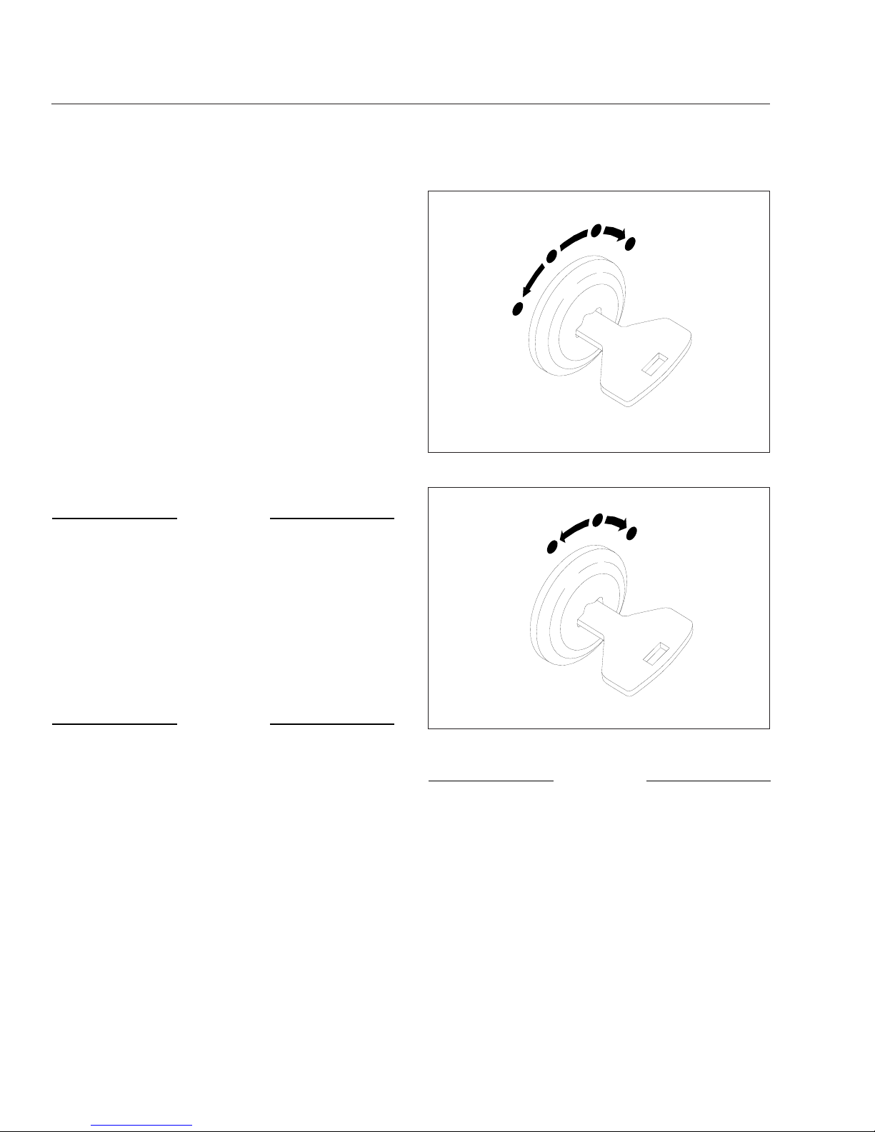
Starting the Engine
IMPORTANT: For service issues and questions,
call 1-800-FTL-HELP and follow the prompts for
gasoline engines. Representatives will be able
to answer questions and diagnose mechanical
issues, as well as provide detailed service repair
information.
General Information
NOTE: Before starting the engine, read Chap-
ter 2
and Chapter 3 in this manual for detailed
information on how to read the instruments and
operate the controls.
Before operating the vehicle, perform the engine
pretrip inspection and daily maintenance checks
in
Chapter 10 and Chapter 11 of this manual.
NOTICE
If a vehicle does not start on the first attempt,
make sure that the engine has completely
stopped rotating before reapplying the starter
switch. Failure to do so can cause the pinion to
release and re-engage, which could cause ring
gear and starter pinion damage.
IMPORTANT: Ring gear and starter pinion damage caused by improper starting procedures is
not warrantable.
NOTICE
Never attempt to start any electronic engine
using ether or any other starting fluid. Serious
engine damage could result.
1.
Set the parking brake.
2.
Turn the ignition switch to the ON position. See
Fig. 15.1 for the four-position ignition switch and
Fig. 15.2 for the three-position ignition switch.
3.
Make sure that the transmission shift control is in
Neutral (N) or Park (P), and that the park brake
is set.
IMPORTANT: Do not depress the throttle pedal
while starting the engine.
4.
Turn the ignition switch to the START position.
After the engine starts, release the key.
NOTICE
Do not crank the engine for more than 30 seconds at a time. Wait two minutes after each try to
allow the starter to cool. Failure to do so could
cause starter damage.
5.
Bring the engine up to operating speed gradually
as it warms up and develops stable oil pressure.
IMPORTANT: When the engine is started, it
takes a short time to build up a lubricating oil
film between the shafts and bearings, and between the pistons and cylinder walls. The oil
pressure gauge indicates any drop in lubricating
07/10/96
1
2
3
4
f601179
1. Accessory (optional)
2. Off
3. On
4. Start
Fig. 15.1, Four-Position Ignition Switch
05/10/2001
1
2
3
f601179a
1. Off 2. On 3. Start
Fig. 15.2, Three-Position Ignition Switch
GM Gasoline Engine
15.1
 Loading...